JP6085232B2 - Game machine - Google Patents

Game machine Download PDF

Info

Publication number
JP6085232B2
JP6085232B2 JP2013163571A JP2013163571A JP6085232B2 JP 6085232 B2 JP6085232 B2 JP 6085232B2 JP 2013163571 A JP2013163571 A JP 2013163571A JP 2013163571 A JP2013163571 A JP 2013163571A JP 6085232 B2 JP6085232 B2 JP 6085232B2
Authority
JP
Japan
Prior art keywords
light
rolling surface
rolling
stage
light emitting
Prior art date
Legal status (The legal status is an assumption and is not a legal conclusion. Google has not performed a legal analysis and makes no representation as to the accuracy of the status listed.)
Active
Application number
JP2013163571A
Other languages
Japanese (ja)
Other versions
JP2015029851A (en
Inventor
真也 中根
真也 中根
裕章 吉原
裕章 吉原
直也 長井
直也 長井
Original Assignee
株式会社ニューギン
Priority date (The priority date is an assumption and is not a legal conclusion. Google has not performed a legal analysis and makes no representation as to the accuracy of the date listed.)
Filing date
Publication date
Application filed by 株式会社ニューギン filed Critical 株式会社ニューギン
Priority to JP2013163571A priority Critical patent/JP6085232B2/en
Publication of JP2015029851A publication Critical patent/JP2015029851A/en
Application granted granted Critical
Publication of JP6085232B2 publication Critical patent/JP6085232B2/en
Active legal-status Critical Current
Anticipated expiration legal-status Critical

Links

Images

Description

この発明は、遊技領域から受け入れた遊技球を転動させた後に遊技領域に排出するよう構成されたステージを備えた遊技機に関するものである。   The present invention relates to a gaming machine including a stage configured to roll a gaming ball received from a gaming area and then discharge the gaming ball to the gaming area.

例えば遊技機の代表例の一つであるパチンコ機は、機内にセットされる遊技盤の盤面に画成した遊技領域の略中央位置に前後に開口する枠状の装飾体(所謂センター役物)が配設されており、この枠状装飾体の開口部を介して複数の図柄を変動表示して図柄変動演出を行う液晶式やドラム式等の図柄表示装置を後方から臨ませると共に、該遊技盤における枠状装飾体の下方位置に、図柄表示装置の変動開始条件としての始動入賞装置(入賞装置)を配設するよう構成したものが多数提案されている。そして、この種の遊技機では、前記遊技領域に打ち出されたパチンコ球(遊技球)が前記始動入賞装置に入賞することにより、前記図柄表示装置で図柄変動演出が開始されてリーチ演出等の各種の遊技演出がなされ、該図柄表示装置に図柄が所定の組み合わせ(例えば同一図柄の3つ揃い)で停止すると、遊技者に有利な所謂大当りが発生するようになっている。このように、大当りが発生するためには、前記始動入賞装置へのパチンコ球の入賞が必要とされることから、遊技者は、前記図柄表示装置での図柄変動演出と同様に、始動入賞装置へのパチンコ球の入賞に対しても大きな関心を持っている。   For example, a pachinko machine, which is one of the representative examples of gaming machines, is a frame-shaped decorative body (so-called center accessory) that opens back and forth at approximately the center position of the gaming area defined on the board surface of the gaming board set in the machine. And a symbol display device such as a liquid crystal type or a drum type that displays a plurality of symbols in a variably displayed manner through the opening of the frame-shaped decorative body, and faces the game from behind. Many proposals have been made in which a start winning device (winning device) as a variation start condition of the symbol display device is arranged below the frame-shaped decorative body on the board. In this type of gaming machine, when the pachinko ball (game ball) launched into the gaming area wins the start winning device, the symbol display effect is started on the symbol display device, and various types of reach effects, etc. When the symbols are displayed on the symbol display device in a predetermined combination (for example, a set of three identical symbols), a so-called jackpot that is advantageous to the player is generated. In this way, in order to generate a big hit, it is necessary to win a pachinko ball to the start winning device, so the player can start start winning device in the same way as the symbol variation effect on the symbol display device. He is also very interested in winning the pachinko ball.

そこで、前記枠状装飾体の下縁部に、パチンコ球が左右方向に転動可能な所謂ステージを設けると共に、遊技領域に開口すると共にステージに連通する球通路を前記枠状装飾体に設けて、遊技領域を流下するパチンコ球をステージに一旦受け入れて、パチンコ球をステージ上で転動させた後に遊技領域へ排出させることで、パチンコ球の動きを楽しませるよう構成した遊技機が知られている(例えば特許文献1参照)。   Therefore, a so-called stage in which the pachinko ball can roll in the left-right direction is provided at the lower edge of the frame-shaped decorative body, and a ball passage that opens to the game area and communicates with the stage is provided in the frame-shaped decorative body. A gaming machine that is configured to entertain pachinko balls' movement by receiving the pachinko balls flowing down the game area once on the stage, rolling the pachinko balls on the stage and then discharging them to the game area is known. (For example, refer to Patent Document 1).

特開2011−104292号公報JP 2011-104292 A

ところで、特許文献1に開示の遊技機では、前記枠状装飾体の下方位置に発光体基板を設置し、発光体基板のLEDを点灯することで、ステージを下方から照明するよう構成されている。ステージを照明することで、ステージ上のパチンコ球の視認性を高める利点があるが、遊技者の興趣を増すために、ステージを利用した更なる発光演出効果の向上が求められている。   By the way, the gaming machine disclosed in Patent Document 1 is configured to illuminate the stage from below by installing a light emitter substrate at a position below the frame-shaped decorative body and turning on an LED of the light emitter substrate. . Illuminating the stage has the advantage of increasing the visibility of the pachinko ball on the stage, but in order to increase the interest of the player, further improvement of the light emission effect using the stage is required.

すなわち本発明は、従来の技術に係る遊技機に内在する前記問題に鑑み、これらを好適に解決するべく提案されたものであって、ステージにおいて効果的な発光演出を行い得る遊技機を提供することを目的とする。   That is, the present invention has been proposed in view of the above-mentioned problems inherent in gaming machines according to the prior art, and provides a gaming machine capable of performing an effective light emission effect on the stage. For the purpose.

前記課題を克服し、所期の目的を達成するため、本願の請求項1に係る発明の遊技機は、
遊技球が流下可能な遊技領域(20a)を前面に有する遊技盤(20)と、この遊技盤(20)の後側に配置された図柄表示装置(18)と、遊技盤(20)に配設され、図柄表示装置(18)の表示部(18a)が内側に臨む窓口(40a)を画成する枠状装飾体(40)と、この枠状装飾体(40)の下枠部(50)内周に設けられ、遊技領域(20a)から受け入れた遊技球を転動させるステージ(56)とを備えた遊技機において、
前記ステージ(56)に設けられ、入射した光を拡散可能な第1の光拡散部(77)が形成されると共に該第1の光拡散部(77)を介して光が透過可能に構成されて、遊技球を転動可能な第1の転動面(72)と、
前記ステージ(56)に前記第1の転動面(72)より後側でかつ上方に延在するように設けられ、光が透過可能に構成されると共に遊技球を転動可能な第2の転動面(78)と、
記第2の転動面(78)の下側に該第2の転動面(78)から離間するように設けられ、入射した光を前記第1の光拡散部(77)と異なる態様で拡散可能な第2の光拡散部(90)と、
記第2の光拡散部(90)より下側に配設され、前記第1の転動面(72)と、第2の光拡散部(90)を介して第2の転動面(78)とを発光可能な発光手段(64)とを備え
前記第1の転動面(72)、前記第2の転動面(78)および前記第2の光拡散部(90)は、左右の外側部側において第1および第2の転動面(72,78)に対して第2の光拡散部(90)が最も近づくと共に中央部において当該第1および第2の転動面(72,78)に対して第2の光拡散部(90)が最も離間するよう左右の延在方向における離間間隔が変化するよう形成されたことを要旨とする。
請求項1に係る発明によれば、発光手段から光を照射することで、第1の転動面と第2の転動面との夫々を、その光拡散態様の違いにより異なる態様で発光装飾することができる。また、第1の光拡散部が第1の転動面に形成されるのに対し、第2の光拡散部が第2の転動面から離間して配設されて、第2の光拡散部で拡散された光が第2の転動面を照明する構成であるから、第1の転動面と第2の転動面との発光装飾の態様の違いを際立たせることができる。また、第1の転動面より上方に延在する第2の転動面と比べて、第1の転動面と発光手段との距離が近いので、第1の光拡散部に加えて第2の光拡散部で光を拡散するよう構成することで、第1の転動面の照明むらをより抑えることができる。
In order to overcome the above-mentioned problems and achieve the intended purpose, a gaming machine according to claim 1 of the present application is
A game board (20) having a game area (20a) in which a game ball can flow down on the front, a symbol display device (18) arranged on the rear side of the game board (20), and a game board (20). A frame-shaped decorative body (40) that defines a window (40a) facing the inside, and a lower frame section (50) of the frame-shaped decorative body (40). In a gaming machine provided with a stage (56) provided on the inner periphery and rolling a game ball received from the game area (20a),
A first light diffusion part (77) provided on the stage (56) and capable of diffusing incident light is formed, and light can be transmitted through the first light diffusion part (77). A first rolling surface (72) capable of rolling the game ball,
The stage (56) is provided so as to extend rearward and upward from the first rolling surface (72), is configured to transmit light, and is capable of rolling a game ball. Rolling surface (78),
Before SL provided so as to be separated from the second rolling surface (78) on the lower side of the second rolling surface (78), aspect the incident light to the first light diffusing portion (77) different A second light diffusing part (90) that can be diffused with,
Is disposed below the front Stories second light diffusing portion (90), said first rolling surface (72), a second rolling surface through the second light diffusing portion (90) ( 78) and a light emitting means (64) capable of emitting light ,
The first rolling surface (72) , the second rolling surface (78), and the second light diffusing portion (90) are arranged on the left and right outer side sides with the first and second rolling surfaces ( 72, 78) and the second light diffusing portion (90) is closest to the second light diffusing portion (90) with respect to the first and second rolling surfaces (72, 78) in the central portion. The gist of the present invention is that the distance between the left and right extending directions is changed so that the distance between them is the most spaced .
According to the first aspect of the present invention, by irradiating light from the light emitting means, the first rolling surface and the second rolling surface are each illuminated in a different manner depending on the difference in the light diffusion manner. can do. In addition, the first light diffusion portion is formed on the first rolling surface, whereas the second light diffusion portion is disposed away from the second rolling surface, so that the second light diffusion portion is formed. Since the light diffused at the portion illuminates the second rolling surface, the difference in the mode of the light-emitting decoration between the first rolling surface and the second rolling surface can be emphasized. Further, since the distance between the first rolling surface and the light emitting means is shorter than the second rolling surface extending upward from the first rolling surface, the first light diffusing portion is added to the second rolling surface. By configuring so that the light is diffused by the two light diffusing portions, the uneven illumination on the first rolling surface can be further suppressed.

請求項2に係る発明では
前記第2の光拡散部(90)は、前記第1の転動面(72)および前記第2の転動面(78)の下側に位置得るよう設けられ、
前記第1の転動面(72)には、前記第1の光拡散部(77)および前記第2の光拡散部(90)の内の両方の光拡散部(77,90)に入射した光が透過するよう構成され、
前記第2の転動面(78)には、前記第1の光拡散部(77)および前記第2の光拡散部(90)の内で第2の光拡散部(90)に入射した光が透過するよう構成されたことを要旨とする。
In the invention according to claim 2 ,
The second light diffusion part (90) is provided so as to be positioned below the first rolling surface (72) and the second rolling surface (78),
The first rolling surface (72) is incident on both the light diffusion portions (77, 90) of the first light diffusion portion (77) and the second light diffusion portion (90). Configured to transmit light,
Light incident on the second rolling surface (78) is incident on the second light diffusing unit (90) among the first light diffusing unit (77) and the second light diffusing unit (90). The gist is that it is configured to transmit .

本願には、次のような技術的思想が含まれている。
前記枠状装飾体(40)には、前記遊技領域(20a)に開口する球入口(58a)から取り込んだ遊技球を前記ステージ(56)の左右方向一側部に開口する球出口(58b)を介して前記転動面(72,78)に導くワープ通路(58)が設けられ、
前記転動面(72,78)におけるステージ(56)の左右方向一側部側の領域と該転動面(72,78)におけるステージ(56)の左右方向他側部側の領域とに対応して一対の前記発光手段(64,64)が配設され、
前記下枠部(50)の前面には、前記転動面(72,78)の左右方向一側部側に対応する前記発光手段(64)の前側に前記下枠飾り部(66)が配設されると共に、前記転動面(72,78)の左右方向他側部側に対応する前記発光手段(64)の前側を被覆する別の下枠飾り部(68)が配設されたことを要旨とする。
この構成によれば、転動面の左右方向一側部側に対応する発光手段の前側に下枠飾り部が配設されると共に、転動面の左右方向他側部側に対応する発光手段の前側を別の下枠飾り部で被覆する構成であるから、下枠部の前面の装飾態様を変化させることができる。
The present application includes the following technical ideas.
In the frame-shaped decorative body (40), a ball exit (58b) that opens a game ball taken from a ball entrance (58a) that opens to the game area (20a) to one side in the left-right direction of the stage (56). A warp passage (58) leading to the rolling surface (72, 78) through
Corresponds to the region of the rolling surface (72, 78) on one side in the left-right direction of the stage (56) and the region of the rolling surface (72, 78) on the other side in the left-right direction of the stage (56). A pair of the light emitting means (64, 64) is provided,
On the front surface of the lower frame portion (50), the lower frame decoration portion (66) is arranged on the front side of the light emitting means (64) corresponding to one side in the left-right direction of the rolling surface (72, 78). And another lower frame decoration portion (68) covering the front side of the light emitting means (64) corresponding to the other side portion in the left-right direction of the rolling surface (72, 78). Is the gist.
According to this configuration , the lower frame decoration portion is disposed on the front side of the light emitting means corresponding to the one side of the rolling surface in the left-right direction, and the light emitting means corresponding to the other side of the rolling surface in the left-right direction. Since the front side is covered with another lower frame decoration portion, the decoration mode of the front surface of the lower frame portion can be changed.

本願には、次のような技術的思想が含まれている。
記ステージ(56)には、該ステージ(56)の中央部側で前記第1の転動面(72)および前記第2の転動面(78)の両方に連なる共通転動面(82,84)が、前記ワープ通路(58)の球出口(58b)に連なる左右方向一側部と左右方向他側部との夫々に設けられ、
前記共通転動面(82,84)には、前記第1の光拡散部と同じ光拡散処理が施されたことを要旨とする。
この構成によれば、ステージ全体として効果的に発光演出を行い得る。
The present application includes the following technical ideas.
The front Symbol stage (56), the first rolling surface at the central portion of the stage (56) (72) and said second common rolling surface continuous to both of the rolling surface (78) (82 , 84) is provided on each of one side portion in the left-right direction and the other side portion in the left-right direction that are connected to the ball outlet (58b) of the warp passage (58),
The gist is that the common rolling surface (82, 84) is subjected to the same light diffusion treatment as that of the first light diffusion portion.
According to this configuration , a light emission effect can be effectively performed as the entire stage.

請求項に係る発明では、
前記発光手段(64)の前側を覆うよう設けられて光が通過可能な通光部(67)が形成された飾り部(66)を備え、
前記発光手段(64)は、前飾り部(66)の通光部(67)の後側を横切って該通光部(67)を上下に区分するように配設された発光基板(64a)と、前第1および第2の転動面(72,78)に向けて光を照射可能な第1の発光体(64b)と、前記通光部(67)に向けて光を照射可能な第2の発光体(64c)とを備え
前記発光基板(64a)における前記第1および第2の転動面(72,78)を向く面に前記第1の発光体(64b)が配設されると共に、当該発光基板(64a)における第1および第2の転動面(72,78)と反対側を向く面に前記第2の発光体(64c)が配設され、
前記飾り部(66)の通光部(67)において前記発光基板(64a)より上側の領域を、前記第1および第2の転動面(72,78)に向けて照射された前記第1の発光体(64b)の光で間接的に照らし、当該飾り部(66)の通光部(67)において発光基板(64a)より下側の領域を、当該通光部(67)に向けて照射された前記第2の発光体(64c)の光で直接的に照らすよう構成されたことを要旨とする。
請求項に係る発明によれば、飾り部に形成された通光部を発光手段の光により発光装飾することができる。また、通光部において発光基板より上側領域から発光基板の上面の第1の発光体から転動面に向けて照射した光が漏れ、通光部において発光基板より下側領域が発光基板の下面の第2の発光体から前方に照射した光によって照らされる。すなわち、通光部の上下で発光装飾の態様を大きく変えることができる。
請求項4に係る発明では、
前記発光手段(64)の前側を覆うよう設けられて光が通過可能な通光部(67)が形成された飾り部(66)を備え、
前記発光手段(64)は、前記飾り部(66)の通光部(67)の後側を横切って該通光部(67)を上下に区分するように配設された発光基板(64a)と、前記第1および第2の転動面(72,78)に向けて光を照射可能な第1の発光体(64b)と、前記通光部(67)に向けて光を照射可能な第2の発光体(64c)とを備え、
前記発光基板(64a)における前記第1および第2の転動面(72,78)を向く面に前記第1の発光体(64b)が配設されると共に、当該発光基板(64a)における第1および第2の転動面(72,78)と反対側を向く面に前記第2の発光体(64c)が配設され、
前記飾り部(66)の通光部(67)において前記発光基板(64a)より上側の領域を、前記第1および第2の転動面(72,78)に向けて照射された前記第1の発光体(64b)の光で間接的に照らすと共に当該通光部(67)に向けて照射された前記第2の発光体(64c9の光で直接的に照らし、当該飾り部(66)の通光部(67)において発光基板(64a)より下側の領域を、当該通光部(67)に向けて照射された前記第2の発光体(64c)の光で直接的に照らすよう構成されたことを要旨とする。
請求項4に係る発明によれば、通光部の上下で発光装飾の態様を大きく変えることができる。
In the invention according to claim 3 ,
A decorative portion (66) provided to cover the front side of the light emitting means (64) and formed with a light transmitting portion (67) through which light can pass;
Said light emitting means (64) is pre-Symbol ornament portion (66) of the light passing portion (67) light emitting substrate vent light section across the side (67) disposed so as to divide vertically after (64a irradiation and), the first light emitter capable of emitting light toward the front Symbol first and second rolling surface (72, 78) and (64b), the light toward the light passage portion (67) A possible second light emitter (64c) ,
The first light emitter (64b) is disposed on a surface of the light emitting substrate (64a) facing the first and second rolling surfaces (72, 78), and the first light emitting substrate (64a) The second light emitter (64c) is disposed on the surface facing the opposite side of the first and second rolling surfaces (72, 78),
In the light transmitting part (67) of the decorative part (66), the first region irradiated from the region above the light emitting substrate (64a) toward the first and second rolling surfaces (72, 78). Indirectly illuminate with the light of the light emitter (64b), and in the light transmitting portion (67) of the decorative portion (66), the region below the light emitting substrate (64a) is directed toward the light transmitting portion (67). The gist is that the second light emitter (64c) irradiated is directly illuminated with light .
According to the invention which concerns on Claim 3 , the light transmission part formed in the decoration part can be light-emitting decorated with the light of a light emission means. Further, light emitted from the first light emitter on the upper surface of the light emitting substrate toward the rolling surface leaks from the region above the light emitting substrate in the light transmitting portion, and the region below the light emitting substrate in the light transmitting portion is the lower surface of the light emitting substrate. Illuminated by light irradiated forward from the second light emitter. That is, the aspect of the light emission decoration can be changed greatly above and below the light transmitting portion.
In the invention according to claim 4,
A decorative portion (66) provided to cover the front side of the light emitting means (64) and formed with a light transmitting portion (67) through which light can pass;
The light emitting means (64) includes a light emitting substrate (64a) disposed so as to vertically divide the light transmitting portion (67) across the rear side of the light transmitting portion (67) of the decorative portion (66). A first light emitter (64b) capable of irradiating light toward the first and second rolling surfaces (72, 78), and a light irradiating toward the light transmitting portion (67). A second light emitter (64c),
The first light emitter (64b) is disposed on a surface of the light emitting substrate (64a) facing the first and second rolling surfaces (72, 78), and the first light emitting substrate (64a) The second light emitter (64c) is disposed on the surface facing the opposite side of the first and second rolling surfaces (72, 78),
In the light transmitting part (67) of the decorative part (66), the first region irradiated from the region above the light emitting substrate (64a) toward the first and second rolling surfaces (72, 78). The light emitting body (64b) is indirectly illuminated with the light and the second light emitting body (64c9 is directly illuminated with the light emitted from the light transmitting section (67), and the decorative portion (66) is illuminated. A structure in which the region below the light emitting substrate (64a) in the light transmitting part (67) is directly illuminated by the light of the second light emitting body (64c) irradiated toward the light transmitting part (67). It is a summary.
According to the invention which concerns on Claim 4, the aspect of a light emission decoration can be changed greatly on the upper and lower sides of a light transmission part.

本願には、次のような技術的思想が含まれている。
記発光手段(64)を構成する発光基板(64a)は、前記下枠部(50)の後面に左右に離間して設けられた一対の係止部(94,95)の間に保持されて左右方向および上下方向に位置決めされると共に、下枠部(50)と該下枠部(50)の後側に配設されて前記第2の転動面(78)の後縁から上方に突出する後壁部(60)との間に保持されて前後方向に位置決めされることを要旨とする。
この構成によれば、発光手段の発光基板の取り付けにネジを用いてないので、発光基板や下枠部にネジ止めのためのスペースが不要になり、発光手段の配設に要するスペースをコンパクトにできる。
The present application includes the following technical ideas.
Emitting substrate constituting the front Symbol emitting means (64) (64a) is held between the pair of locking portions provided at a distance from each other in the right and left on the rear surface of the lower frame portion (50) (94, 95) Are positioned in the left-right direction and the up-down direction, and are disposed on the rear side of the lower frame portion (50) and the lower frame portion (50), and upward from the rear edge of the second rolling surface (78). The gist is that it is held between the protruding rear wall portion (60) and positioned in the front-rear direction.
According to this configuration , since no screws are used to attach the light emitting substrate of the light emitting means, a space for screwing is not required on the light emitting substrate or the lower frame portion, and the space required for arranging the light emitting means is made compact. it can.

本発明に係る遊技機によれば、ステージにおいて効果的な発光演出を行うことができる。   According to the gaming machine according to the present invention, an effective light emission effect can be performed on the stage.

本発明の好適な実施例に係るパチンコ機を示す正面図である。1 is a front view showing a pachinko machine according to a preferred embodiment of the present invention. 実施例の遊技盤を示す正面図である。It is a front view which shows the game board of an Example. 図2のA−A線断面図である。It is the sectional view on the AA line of FIG. 実施例の枠状装飾体、遊技盤および設置部材を分解して示す斜視図である。It is a perspective view which decomposes | disassembles and shows the frame-shaped decorative body, game board, and installation member of an Example. 実施例の枠状装飾体を示す正面図である。It is a front view which shows the frame-shaped decoration body of an Example. (a)は実施例の枠状装飾体の左側面図であり、(b)は図5のB−B線断面図である。(a) is the left view of the frame-shaped decorative body of an Example, (b) is the BB sectional drawing of FIG. (a)は実施例の枠体装飾体の要部背面図であり、(b)は(a)から後壁部材を取り外した状態を示す。(a) is a principal part rear view of the frame decoration body of an Example, (b) shows the state which removed the rear wall member from (a). (a)は下段転動面で破断した縦断面図であり、(b)は上段転動面で破断した縦断面図である。(a) is the longitudinal cross-sectional view fractured | ruptured by the lower stage rolling surface, (b) is the longitudinal cross-sectional view fractured | ruptured by the upper stage rolling surface. 装飾体基部への発光基板の取り付け構造を示す説明図である。It is explanatory drawing which shows the attachment structure of the light emission board | substrate to a decoration body base. 実施例の下枠飾り部と発光手段との関係を示す説明図である。It is explanatory drawing which shows the relationship between the lower frame decoration part of an Example, and a light emission means. ステージ、光拡散部材および発光手段の関係を示す説明図である。It is explanatory drawing which shows the relationship between a stage, a light-diffusion member, and a light emission means. 実施例の枠体装飾体を前側から見た分解斜視図である。It is the disassembled perspective view which looked at the frame decoration body of the Example from the front side. 実施例の枠体装飾体を後側から見た分解斜視図である。It is the disassembled perspective view which looked at the frame decoration body of the Example from the back side. (a)は実施例のステージを示す平面図であり、(b)は実施例の光拡散部材を示す平面図である。(a) is a top view which shows the stage of an Example, (b) is a top view which shows the light-diffusion member of an Example. (a)は実施例のステージを示す底面図であり、(b)は実施例の光拡散部材を示す底面図である。(a) is a bottom view showing the stage of the embodiment, (b) is a bottom view showing the light diffusion member of the embodiment. 変更例の下枠飾り部と発光手段との関係を示す説明図である。It is explanatory drawing which shows the relationship between the lower frame decoration part of the example of a change, and a light emission means.

次に、本発明に係る遊技機につき、好適な実施例を挙げて、添付図面を参照して以下に説明する。なお、実施例では、遊技球としてパチンコ球を用いて遊技を行うパチンコ機を例に挙げて説明する。また、以下の説明において、「前」、「後」、「左」、「右」とは、特に断りのない限り、図1に示すようにパチンコ機を前側(遊技者側)から見た状態で指称する。   Next, the gaming machine according to the present invention will be described below with reference to the accompanying drawings by way of preferred embodiments. In the embodiment, a pachinko machine that plays a game using a pachinko ball as a game ball will be described as an example. Further, in the following description, “front”, “rear”, “left”, and “right” are states when the pachinko machine is viewed from the front side (player side) as shown in FIG. 1 unless otherwise specified. It points at.

(パチンコ機10について)
図1に示すように、実施例に係るパチンコ機10は、前後に開口する矩形枠状に形成されて遊技店の図示しない設置枠台に縦置き姿勢で設置される固定枠としての外枠11の開口前面側に、遊技盤20を着脱可能に保持する本体枠としての中枠12が開閉および着脱可能に組み付けられて、該遊技盤20の裏側に、各種図柄を変動表示可能な図柄表示装置18(図3参照)が着脱可能に配設されている。また、前記中枠12の前面側には、前記遊技盤20を透視保護するガラス板や透明な合成樹脂材により形成された透視保護板13bで前後に開口する窓部13aを覆うよう構成された前枠13が開閉可能に組み付けられると共に、該前枠13の下方にパチンコ球を貯留する下球受け皿15が開閉可能に組み付けられる。なお、実施例では、前記前枠13の下部位置に、パチンコ球を貯留する上球受け皿14が一体的に組み付けられており、前枠13の開閉に合わせて上球受け皿14も一体的に開閉するよう構成される。なお、実施例では、前記図柄表示装置18としては、各種図柄を表示可能な液晶パネルを収容ケースに収容した液晶表示装置が採用されるが、これに限られるものではなく、ドラム式の図柄表示装置やドットマトリックス式の図柄表示装置等の各種図柄を停止および変動表示可能な従来公知の各種の図柄表示装置を採用し得る。また、前記上球受け皿14は、前記前枠13と別体に形成してもよい。なお、球受け皿については、上下2枚の球受け皿14,15を備えるものに限らず、1枚の球受け皿のみを設ける構成であってもよい。
(About pachinko machine 10)
As shown in FIG. 1, a pachinko machine 10 according to an embodiment is formed in a rectangular frame shape that opens forward and backward, and an outer frame 11 as a fixed frame that is installed in a vertically installed posture on an installation frame base (not shown) of a game shop. A symbol frame display device capable of variably displaying various symbols on the back side of the game board 20 by assembling the middle frame 12 as a main body frame for detachably holding the game board 20 to the opening front side of the game board 20 18 (see FIG. 3) is detachably disposed. In addition, the front side of the middle frame 12 is configured to cover the window portion 13a opening front and rear with a glass plate for transparently protecting the game board 20 and a transparent protective plate 13b formed of a transparent synthetic resin material. The front frame 13 is assembled so as to be openable and closable, and a lower ball tray 15 for storing pachinko balls is assembled below the front frame 13 so as to be openable and closable. In the embodiment, an upper ball tray 14 for storing pachinko balls is integrally assembled at a lower position of the front frame 13, and the upper ball tray 14 is also opened and closed integrally with the opening and closing of the front frame 13. Configured to do. In the embodiment, a liquid crystal display device in which a liquid crystal panel capable of displaying various symbols is housed in a housing case is adopted as the symbol display device 18, but is not limited to this, and a drum-type symbol display is used. Various conventionally known symbol display devices capable of stopping and variably displaying various symbols such as a device and a dot matrix type symbol display device can be adopted. Further, the upper ball tray 14 may be formed separately from the front frame 13. It should be noted that the ball tray is not limited to the one having the upper and lower two ball trays 14 and 15 and may be configured to have only one ball tray.

前記前枠13の右下方位置には、前記中枠12に配設された打球発射装置(図示せず)を作動する操作ハンドル17が設けられている。前記操作ハンドル17は、左回転方向に付勢された操作レバー17aを備えており、該操作レバー17aを右回転するよう遊技者が回動操作することで打球発射装置が作動されて、前記上球受け皿14に貯留されたパチンコ球が前記遊技盤20に向けて発射されるようになっている。ここで、前記操作レバー17aの回動量に応じて打球発射装置によるパチンコ球の打球力が強弱変化するよう構成されており、遊技者が操作レバー17aの回動量を操作することで、前記遊技盤20における遊技領域20aの左側にパチンコ球を流下させる所謂「左打ち」と、該遊技領域20aの右側にパチンコ球を流下させる所謂「右打ち(ゴム打ち)」とを打ち分け得るようになっている。   An operation handle 17 for operating a ball striking device (not shown) disposed on the middle frame 12 is provided at a lower right position of the front frame 13. The operation handle 17 includes an operation lever 17a urged in the left rotation direction. When the player rotates the operation lever 17a to rotate right, the hitting ball launching device is operated, Pachinko balls stored in the ball tray 14 are launched toward the game board 20. Here, the hitting force of the pachinko ball by the hitting ball launcher is changed in accordance with the amount of rotation of the operation lever 17a, and the player operates the amount of rotation of the operation lever 17a. The so-called “left-handed” that causes the pachinko ball to flow down to the left of the game area 20a in FIG. 20 and the so-called “right-handed (rubber-made)” that causes the pachinko ball to flow down to the right of the gaming area 20a can be distinguished. Yes.

(遊技盤20について)
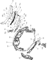
図2に示すように、前記遊技盤20は、所定板厚の略矩形状に形成された木材板の表面に、各種絵柄等が描かれた合成樹脂シート(図示せず)等を貼付けて装飾した板部材であって、該遊技盤20の表面(盤面)に配設された略円形状に湾曲形成する案内レール23により、パチンコ球が流下可能な遊技領域20aが画成されている。また、前記遊技盤20の裏面に、前記図柄表示装置18が取り付けられた設置部材19(図4参照)が配設されている。
(About game board 20)
As shown in FIG. 2, the game board 20 is decorated with a synthetic resin sheet (not shown) on which various patterns are drawn on the surface of a wood board formed in a substantially rectangular shape with a predetermined board thickness. A game area 20a in which a pachinko ball can flow down is defined by a guide rail 23 that is a curved member formed in a substantially circular shape and disposed on the surface (board surface) of the game board 20. Further, an installation member 19 (see FIG. 4) to which the symbol display device 18 is attached is disposed on the back surface of the game board 20.

図2に示すように、前記案内レール23は、遊技盤20の左下部から右上部に至るよう左方向に膨出する円弧状に形成された外レール24と、遊技盤20の右上部、右下部および左上部に至るよう右方向に膨出する円弧状に形成された内レール25,26とから構成されている。前記内レール25,26は、外レール24の右上端部に連接して遊技盤20の右上部から下部に亘って配設され、左端縁が右方に凹む円弧状に形成された盤面飾り部材25と、遊技盤20の下部から左上部に亘って配設されて盤面飾り部材25の下端部に連接し、前記外レール24の右方(内側)に離間して位置するレール部材26とから構成され、該外レール24およびレール部材26により1個のパチンコ球が通過可能な発射通路23aが画成されている。ここで、前記内レールを構成するレール部材26は、前記遊技盤20の左上部に開放端を臨ませて外レール24との間に遊技領域20aに開口する打出口23bを画成するよう構成されて、前記打球発射装置から発射されたパチンコ球が発射通路23aの下方開口から上昇して、レール部材26の開放端側の打出口23bから遊技領域20a内に打ち出されるようになっている。   As shown in FIG. 2, the guide rail 23 includes an outer rail 24 formed in an arc shape that bulges leftward from the lower left part of the game board 20 to the upper right part, and an upper right part and a right part of the game board 20. It is comprised from the inner rails 25 and 26 formed in the arc shape which bulges rightward so that a lower part and upper left part may be reached. The inner rails 25 and 26 are connected to the upper right end portion of the outer rail 24 and are arranged from the upper right portion to the lower portion of the game board 20, and the left end edge is formed in a circular arc shape recessed in the right direction. 25 and a rail member 26 which is arranged from the lower part to the upper left part of the game board 20 and is connected to the lower end part of the board decoration member 25 and is spaced apart to the right (inner side) of the outer rail 24. The outer rail 24 and the rail member 26 constitute a launch passage 23a through which one pachinko ball can pass. Here, the rail member 26 that constitutes the inner rail is configured to define a batting opening 23b that opens to the game area 20a with the open end facing the upper left portion of the gaming board 20 and the outer rail 24. Then, the pachinko ball launched from the hitting ball launching device rises from the lower opening of the launch passage 23a, and is launched into the game area 20a from the launch outlet 23b on the open end side of the rail member 26.

(遊技盤20の装着口28)
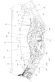
図4に示すように、前記遊技盤20には、前後に貫通する装着口28が前記遊技領域20a内に複数開設されて、各装着口28に対して各種部品が前側から取り付けられると共に、遊技領域20aの最下部位置には、該遊技領域20aに打ち出されたパチンコ球を排出するアウト口29が開設されている。また、前記遊技盤20には、前記遊技領域20a内に多数の遊技釘30が植設されており、遊技領域20aを流下するパチンコ球が遊技釘30に接触することでパチンコ球の流下方向を不規則に変化させるようになっている。なお、前記装着口28の形成数は、遊技盤20に対して取り付けられる各種部品の個数や配設位置等により必要に応じて適宜決定される。
(Mounting slot 28 of the game board 20)
As shown in FIG. 4, the game board 20 has a plurality of mounting holes 28 penetrating in the front-rear direction in the game area 20a, and various parts are attached to the mounting holes 28 from the front side. At the lowermost position of the area 20a, an out port 29 for discharging a pachinko ball launched into the game area 20a is provided. The gaming board 20 has a large number of game nails 30 planted in the game area 20a, and the pachinko balls flowing down the game area 20a come into contact with the game nails 30 so that the flow direction of the pachinko balls is reduced. It is designed to change irregularly. It should be noted that the number of the mounting openings 28 is appropriately determined depending on the number of various parts attached to the game board 20 and the arrangement positions.

図4に示すように、実施例の前記遊技盤20には、前記案内レール23で囲まれた遊技領域20aの略中央の大部分が開口する第1装着口28に、前後に開口する窓口40aが形成された枠状装飾体40が取り付けられ、該枠状装飾体40の窓口40aを介して図柄表示装置18の表示部18aが遊技盤20の前面側に臨むよう構成されている。そして、第1装着口28(枠状装飾体40)の下方に開設された第2装着口(図示せず)に、遊技領域20aを流下するパチンコ球が入賞可能な始動入賞口32aを有する始動入賞装置32が取り付けられ、該第2装着口(第1始動入賞装置32)の右上方に開設された第3装着口(図示せず)に、遊技領域20aを流下するパチンコ球が入賞可能な特別入賞装置33が取り付けられている。また、実施例のパチンコ機10では、前記枠状装飾体40における特別入賞装置33の上方であって遊技領域20aにおける右側の流路に臨む位置に、該流路を流下するパチンコ球が入賞可能な第2始動入賞口34aを有する第2始動入賞装置34が取り付けられている。   As shown in FIG. 4, the game board 20 according to the embodiment has a window 40a that opens to the front and rear in a first mounting opening 28 that is open at a substantial center of a game area 20a surrounded by the guide rails 23. A frame-shaped decorative body 40 is attached, and the display unit 18a of the symbol display device 18 faces the front side of the game board 20 through a window 40a of the frame-shaped decorative body 40. A start having a start winning opening 32a into which a pachinko ball flowing down the game area 20a can win a second mounting opening (not shown) opened below the first mounting opening 28 (frame-like decorative body 40). A winning device 32 is attached, and a pachinko ball flowing down the game area 20a can win a prize at a third mounting port (not shown) opened on the upper right side of the second mounting port (first start winning device 32). A special winning device 33 is attached. Further, in the pachinko machine 10 of the embodiment, the pachinko ball flowing down the flow path can be awarded at a position facing the right flow path in the game area 20a above the special winning device 33 in the frame-shaped decorative body 40. A second start winning device 34 having a second start winning port 34a is attached.

そして、前記第1始動入賞装置32に設けられた第1始動入賞口32aまたは第2始動入賞装置34に設けられた第2始動入賞口34aに遊技領域20aを流下するパチンコ球が入賞することで、前記図柄表示装置18の表示部18aにおいて図柄が変動表示されて図柄変動演出が展開され、該図柄変動演出の結果、図柄表示装置18の表示部18aに所定の図柄組み合わせ(例えば同一図柄の3つ揃い等)で図柄が停止表示されることで所謂大当り(当り)が発生し、大当りの発生に伴って前記特別入賞装置33が開放して多数の賞球を獲得し得る機会が与えられるようになっている。ここで、前記第1始動入賞装置32は、第1始動入賞口32aが遊技領域20aに常時開放する常時開放型の入賞装置とされ、前記第2始動入賞装置34は、所定の開放条件および閉鎖条件(何れも後述)に従って第2始動入賞口34aが開閉部材35により開閉される開閉型の入賞装置とされている。そして、前記特別入賞装置33は、開閉体33aにより特別入賞口(図示せず)を常には閉鎖(入賞不能状態と)するよう構成され、大当りの発生に伴って特別入賞口を開放(入賞可能状態と)するよう構成されている。   Then, the pachinko ball flowing down the game area 20a wins the first start prize port 32a provided in the first start prize device 32 or the second start prize port 34a provided in the second start prize device 34. The symbols are variably displayed on the display unit 18a of the symbol display device 18 to develop a symbol variation effect. As a result of the symbol variation effect, a predetermined symbol combination (for example, 3 of the same symbol) is displayed on the display unit 18a of the symbol display device 18. When the symbols are stopped and displayed in the assortment, etc., so-called big hits (winning) occur, and the special winning device 33 is opened with the occurrence of the big hits so as to be given an opportunity to obtain a large number of prize balls. It has become. Here, the first start winning device 32 is a normally open type winning device in which the first start winning port 32a is always open to the game area 20a, and the second start winning device 34 has a predetermined opening condition and closing. According to the conditions (both described later), the second start winning opening 34a is an open / close type winning device that is opened / closed by an opening / closing member 35. The special prize winning device 33 is configured to always close a special prize opening (not shown) by the opening / closing body 33a (a state in which a prize cannot be made), and the special prize opening is opened (a prize can be awarded) when a big hit occurs. Configured to state).

実施例のパチンコ機10では、遊技が行われる遊技状態として3つの状態が設定されている。すなわち、パチンコ機10において通常行われる通常状態と、該通常状態に比べて大当りの発生確率が高く、かつ前記第2始動入賞装置34の第2始動入賞口34aへの入賞確率が高く設定された確率変動状態と、通常状態に比べて大当りの発生確率が同等で、かつ第2始動入賞装置34の第2始動入賞口34aへの入賞確率が高く設定された時間短縮状態が設定されている。そして、前記第1始動入賞口32aまたは第2始動入賞口34aへパチンコ球が入賞した際に、前記遊技状態を変更するか否かがパチンコ機10裏側に配設された制御装置(図示せず)で決定される。   In the pachinko machine 10 of the embodiment, three states are set as game states in which a game is performed. That is, the normal state normally performed in the pachinko machine 10 is set to have a higher probability of winning a big hit than the normal state, and the winning probability to the second start winning port 34a of the second start winning device 34 is set high. A time reduction state is set in which the probability of winning the jackpot is equal to the probability variation state and the normal state, and the winning probability to the second starting winning port 34a of the second starting winning device 34 is set high. Then, when a pachinko ball wins the first start winning opening 32a or the second start winning opening 34a, whether or not to change the gaming state is controlled on the back side of the pachinko machine 10 (not shown). )

図2に示すように、前記第2始動入賞装置34の右上方には、前記遊技領域20aにおける右側の流路を流下するパチンコ球が通過可能な球通過ゲート36が設けられると共に、パチンコ球を検出する球通過検出センサ(図示せず)が球通過ゲート36に設けられている。前記球通過ゲート36の球通過検出センサは、前記制御装置に接続されており、該球通過検出センサの検出に伴って前記第2始動入賞装置34における第2始動入賞口34aを開放するか否かの始動口開放抽選が行われ、該始動口開放抽選の結果が当選の場合に、第2始動入賞口34aを開放するよう第2始動入賞装置34が駆動制御されるようになっている。すなわち、実施例のパチンコ機10では、前記球通過ゲート36の球通過検出センサがパチンコ球を検出して行われる始動口開放抽選の結果が当選となることが、前記第2始動入賞装置34の第2始動入賞口34aを開放する開放条件とされている。   As shown in FIG. 2, a ball passing gate 36 through which a pachinko ball flowing down the right flow path in the game area 20a can pass is provided at the upper right of the second start winning device 34, and the pachinko ball A ball passage detection sensor (not shown) for detection is provided in the ball passage gate 36. The ball passage detection sensor of the ball passage gate 36 is connected to the control device, and whether or not to open the second start winning port 34a in the second start winning device 34 in accordance with the detection of the ball passage detection sensor. When the start opening lottery is performed and the result of the opening opening lottery is a win, the second start winning device 34 is driven and controlled to open the second start winning opening 34a. That is, in the pachinko machine 10 of the embodiment, the result of the start opening lottery performed when the ball passage detection sensor of the ball passage gate 36 detects the pachinko ball is won, and the second start winning device 34 An opening condition for opening the second start winning opening 34a is set.

そして、前記第2始動入賞口34aを開放してから所定の閉鎖条件が成立することで、該第2始動入賞口34aが閉鎖されるようになっている。ここで、前記第2始動入賞口34aを閉鎖する閉鎖条件としては、例えば前記開閉部材35が入賞許容位置に移動してからの経過時間(第2始動入賞口34aの開放時間)や、第2始動入賞口34aへの設定数のパチンコ球の入賞等が挙げられるが、これに限られるものではない。すなわち、パチンコ機10において入賞口を開閉する開閉式の始動入賞装置に採用される開閉部材35の開放条件および閉鎖条件に従って第2始動入賞装置34が駆動制御される。   The second start winning opening 34a is closed when a predetermined closing condition is satisfied after the second starting winning opening 34a is opened. Here, as a closing condition for closing the second start winning opening 34a, for example, an elapsed time (opening time of the second start winning opening 34a) after the opening / closing member 35 has moved to the winning allowable position, Examples include, but are not limited to, winning a predetermined number of pachinko balls in the start winning opening 34a. That is, the second start winning device 34 is driven and controlled in accordance with the opening and closing conditions of the opening / closing member 35 employed in the open / close type starting winning device that opens and closes the winning opening in the pachinko machine 10.

(特定条件について)
実施例のパチンコ機10では、前記第2始動入賞装置34の第2始動入賞口34aを開放する開放条件および該第2始動入賞口34aを閉鎖する閉鎖条件は、遊技状態に応じて設定されている。すなわち、遊技状態が前記確率変動状態および時間短縮状態の場合には、遊技状態が通常状態の場合に比べて、前記第2始動入賞装置34の第2始動入賞口34aが開放され易くなるよう前記開放条件や閉鎖条件が設定されて、第2始動入賞口34aへの入賞率を高くするよう構成されている。具体的には、実施例では、遊技状態が前記確率変動状態および時間短縮状態の場合には、遊技状態が通常状態の場合に比べて、前記始動口開放抽選の結果が確定するまでの時間が短くなるよう設定されると共に、第2始動入賞口34aの1回の開放毎の開放時間を長く設定することで、確率変動状態および時間短縮状態における第2始動入賞口34aへの入賞確率を高くしている。例えば、遊技状態が通常状態の場合には、始動口開放抽選の結果が確定するまでの時間が略30秒で、かつ第2始動入賞口34aの開放時間が0.1秒/1回に設定されるのに対し、遊技状態が確率変動状態および時間短縮状態の場合には、始動口開放抽選の結果が確定するまでの時間が略2秒で、かつ第2始動入賞口34aの開放時間が2秒/1回に設定されている。
(About specific conditions)
In the pachinko machine 10 of the embodiment, the opening condition for opening the second start winning port 34a and the closing condition for closing the second start winning port 34a of the second start winning device 34 are set according to the gaming state. Yes. That is, when the gaming state is the probability variation state and the time shortening state, the second start winning opening 34a of the second start winning device 34 is more easily opened than when the gaming state is the normal state. An opening condition and a closing condition are set, and the winning rate to the second start winning opening 34a is increased. Specifically, in the embodiment, when the gaming state is the probability variation state and the time shortening state, the time until the result of the start port opening lottery is determined as compared to when the gaming state is the normal state. By setting the opening time to be shorter and setting the opening time for each opening of the second start winning opening 34a to be longer, the winning probability to the second starting winning opening 34a in the probability variation state and the time shortening state is increased. doing. For example, when the gaming state is a normal state, the time until the result of the start opening lottery is determined is approximately 30 seconds and the opening time of the second start winning opening 34a is set to 0.1 second / one time. On the other hand, when the gaming state is the probability variation state and the time shortening state, the time until the result of the start opening lottery is determined is about 2 seconds, and the opening time of the second start winning opening 34a is It is set to 2 seconds / 1 time.

そして、前記特別入賞装置33および第2始動入賞装置34の夫々を、前記遊技領域20aの右側部に配置したことで、パチンコ球が遊技領域20aの左側部を流下する場合に比べて、遊技領域20aの右側部を流下する場合の方が、各入賞装置33,34に入賞し易くなっている。従って、実施例のパチンコ機10は、特定の条件が成立した場合(大当り状態、遊技状態が確率変動遊技状態または時間短縮遊技状態となった場合)に、パチンコ球を枠状装飾体40の右側(遊技領域20aの右側部)を流下するように打ち出す「右打ち(ゴム打ち)」を実施し、特定条件が不成立の場合には、パチンコ球を枠状装飾体40の左側(遊技領域20aの左側部)を流下するように打ち出す「左打ち」を実施することで、所定の遊技が行われるよう構成されている。このように、遊技者が遊技状態(特定条件の成立・不成立)に応じて前記操作ハンドル17を操作してパチンコ球の打ち出し位置を変更するよう構成することで、遊技者に能動的な遊技参加を促し、遊技の興趣を高めるようになっている。すなわち、実施例において特定条件の成立とは、パチンコ球を右側の流路へ打ち出す「右打ち(ゴム打ち)」を実施するのに適した条件の成立をいうものである。   Then, the special winning device 33 and the second start winning device 34 are arranged on the right side of the gaming area 20a, so that the game area is smaller than the case where the pachinko ball flows down the left side of the gaming area 20a. In the case of flowing down the right side of 20a, it is easier to win the winning devices 33 and 34. Therefore, the pachinko machine 10 according to the embodiment places the pachinko ball on the right side of the frame-shaped decorative body 40 when a specific condition is satisfied (when the big hit state, the gaming state becomes a probability variation gaming state, or a time shortening gaming state). When the “right strike (rubber strike)” is performed so as to flow down (the right side of the game area 20a) and the specific condition is not satisfied, the pachinko ball is placed on the left side of the frame-shaped decorative body 40 (the game area 20a). A predetermined game is configured to be performed by performing “left-handed” that strikes down the left side). In this way, by configuring the player to change the launch position of the pachinko ball by operating the operation handle 17 according to the gaming state (satisfaction / non-satisfaction of the specific condition), the player can actively participate in the game. To increase the interest of the game. That is, the establishment of the specific condition in the embodiment means the establishment of a condition suitable for performing “right hitting (rubber hitting)” in which the pachinko ball is shot into the right channel.

(設置部材19について)
前記設置部材19は、前記遊技盤20の外郭形状と略整合する大きさおよび形状に形成された略矩形状の背面板と、該背面板の外周縁部から前方に突出する画壁部とから前方に開口した箱状に形成されて、該画壁部の開口前端部を遊技盤20の裏面に当接させた状態で、当該遊技盤20と設置部材19とがネジにより固定される。そして、前記設置部材19において前記遊技盤20との間に画成される空間に、各種の可動演出装置や各種の発光装置等が設置されて、設置部材19をベースとする1つのユニットとして扱い得るようになっている。また、前記設置部材19の背面板には、前記枠状装飾体40の窓口40aを前後に整列する位置に、略矩形状の開口部19aが前後に開口するよう開設されると共に、該背面板の裏側に前記図柄表示装置18が着脱自在に取り付けられて、該開口部19aを介して図柄表示装置18の表示部18aが遊技盤20の前側に臨むようになっている。
(About the installation member 19)
The installation member 19 includes a substantially rectangular back plate formed in a size and shape that substantially matches the outline shape of the game board 20, and an image wall portion that protrudes forward from the outer peripheral edge of the back plate. The game board 20 and the installation member 19 are fixed with screws in a state of being formed in a box shape opened forward and with the opening front end of the drawing wall part in contact with the back surface of the game board 20. In the space defined between the game board 20 and the installation member 19, various movable effect devices, various light emitting devices, and the like are installed and treated as a single unit based on the installation member 19. To get. In addition, the back plate of the installation member 19 is opened so that a substantially rectangular opening 19a is opened in the front and back at a position where the window 40a of the frame-shaped decorative body 40 is aligned in the front and back. The symbol display device 18 is detachably attached to the back side of the display panel 18 so that the display portion 18a of the symbol display device 18 faces the front side of the game board 20 through the opening 19a.

(枠状装飾体40について)
図5〜図13に示すように、前記枠状装飾体40は、環状に形成されて各種部材の設置部分となる装飾体基部42と、該装飾体基部42の後面から後方へ突出するよう形成され、前記遊技盤20に開設された前記第1装着口28の内側に沿って延在する板状の装飾体固定部44と、該装飾体基部42に設けられて前記遊技盤20の前面より前方に突出し、前記遊技領域20aと図柄表示装置18の表示部18a(表示領域)を区切る庇状部46と、該庇状部46の後縁から外方に延出する板状の装飾体取付部48とを備えている。枠状装飾体40は、装飾体固定部44を第1装着口28に挿入すると共に装飾体取付部48を遊技盤20の前面に当接した状態で、該装飾体取付部48をネジ等で遊技盤20に固定することで遊技盤20に取り付けられる。ここで、庇状部46は、枠状装飾体40(装飾体基部42)の左側縁の中間位置から上縁および右下縁に亘って連続して延在するよう設けられており、図柄表示装置18の前面側を横切ってパチンコ球が流下(落下)するのを規制している。また、枠状装飾体40の左側縁下部および下縁(特に区別する場合は下枠部50という)には、前記庇状部46が設けられず、前側をパチンコ球が通過可能に構成されている。また、実施例の枠状装飾体40の上縁部および側縁部には、各種の意匠が施された飾り体51,52,53や透光性の飾り体51,52,53を発光させる照明手段54などが配設されている。なお、枠状装飾体40は、装飾体基部42、装飾体固定部44、庇状部46および装飾体取付部48の全てあるいはこれらのうちで組み合わせて樹脂により一体成形しても、別部材を組み合わせる構成の何れであってもよい。また、実施例の装飾体基部42は、透明な樹脂板で構成されて、光を透過可能になっている。
(About the frame-shaped decorative body 40)
As shown in FIG. 5 to FIG. 13, the frame-shaped decorative body 40 is formed in a ring shape so as to project from the rear surface of the decorative body base portion 42, and a decorative body base portion 42 that serves as an installation portion for various members. And a plate-shaped decorative body fixing portion 44 extending along the inside of the first mounting opening 28 established in the game board 20, and provided on the decorative body base portion 42 from the front surface of the game board 20. A hook-like part 46 that protrudes forward and separates the game area 20a from the display part 18a (display area) of the symbol display device 18, and a plate-like decorative body that extends outward from the rear edge of the hook-like part 46 Part 48. The frame-shaped decorative body 40 is inserted with the decorative body fixing portion 44 into the first mounting opening 28 and the decorative body mounting portion 48 is in contact with the front surface of the game board 20, and the decorative body mounting portion 48 is screwed or the like. It is attached to the game board 20 by being fixed to the game board 20. Here, the hook-shaped portion 46 is provided so as to continuously extend from the middle position of the left edge of the frame-shaped decorative body 40 (decorative body base portion 42) to the upper edge and the lower right edge. The pachinko ball is restricted from flowing down (falling) across the front side of the device 18. Further, the lower left edge and the lower edge of the frame-shaped decorative body 40 (referred to as the lower frame portion 50 in particular) are not provided with the hook-shaped portion 46, and the pachinko ball can pass through the front side. Yes. Moreover, the decorative body 51,52,53 or the translucent decorative body 51,52,53 which gave various designs is light-emitted on the upper edge part and side edge part of the frame-shaped decorative body 40 of an Example. Illumination means 54 and the like are provided. It should be noted that the frame-shaped decorative body 40 may be formed by integrally forming the decorative body base portion 42, the decorative body fixing portion 44, the collar-shaped portion 46, and the decorative body mounting portion 48, or a combination of them, with a separate member. Any of the combinations may be used. Moreover, the decorative body base 42 of the embodiment is made of a transparent resin plate and can transmit light.

図5に示すように、前記枠状装飾体40は、下枠部50の内周(窓口40aの下側)に設けられたステージ56と、該枠状装飾体40の左側縁(窓口40aの左側)に、遊技領域20aから取り込んだパチンコ球をステージ56に導くワープ通路58とを備えている。ワープ通路58または枠状装飾体40の左側縁下部前側を通って遊技領域20aからステージ56に入ったパチンコ球は、ステージ56上を左右に転動した後に、下枠部50の前側を通って遊技領域20aに排出される。ここで、ワープ通路58の球出口58bは、ステージ56の左側部(左右方向一側部)に右側方へ向けて開口しており、遊技領域20aに開口する球入口58aを介してワープ通路58に流入したパチンコ球を球出口58bからステージ56に右側方へ向けて送り出されるようになっている。また、ステージ56の後側には、左右方向の全長に亘って後壁部材(後壁部)60が上側に向けて所定高さで立ち上がっており、ステージ56上を転動するパチンコ球が図柄表示装置18の表示部18a側に移動するのを該後壁部材60で防止している。更に、図12および図13に示すように、下枠部50は、該下枠部50を構成する装飾体基部42に配設された光拡散部材62と、該光拡散部材62を介してステージ56に向けて光を照射可能な発光手段64,64と、該装飾体基部42の前側に発光手段64,64を覆うように配設され、該下枠部50の前面を構成する下枠飾り部66,68とを備えている。   As shown in FIG. 5, the frame-shaped decorative body 40 includes a stage 56 provided on the inner periphery of the lower frame portion 50 (below the window 40a) and the left edge of the frame-shaped decorative body 40 (the window 40a). On the left side), a warp passage 58 for guiding a pachinko ball taken from the game area 20 a to the stage 56 is provided. The pachinko ball that has entered the stage 56 from the game area 20a through the warp passage 58 or the lower front side of the left edge of the frame-shaped decorative body 40 rolls left and right on the stage 56 and then passes through the front side of the lower frame portion 50. It is discharged into the game area 20a. Here, the ball outlet 58b of the warp passage 58 opens toward the right side at the left side portion (one side portion in the left-right direction) of the stage 56, and the warp passage 58 passes through the ball inlet 58a that opens into the game area 20a. The pachinko balls that have flowed into the ball are sent out to the stage 56 from the ball outlet 58b toward the right side. Further, on the rear side of the stage 56, a rear wall member (rear wall portion) 60 stands up at a predetermined height over the entire length in the left-right direction, and a pachinko ball that rolls on the stage 56 is designed. The rear wall member 60 prevents the display device 18 from moving toward the display unit 18a. Further, as shown in FIGS. 12 and 13, the lower frame portion 50 includes a light diffusing member 62 disposed on a decorative body base 42 constituting the lower frame portion 50, and a stage via the light diffusing member 62. Light emitting means 64, 64 capable of irradiating light toward 56, and a lower frame decoration that is disposed on the front side of the decorative body base 42 so as to cover the light emitting means 64, 64 and constitutes the front surface of the lower frame part 50 Parts 66 and 68.

図2、図5および図6に示すように、前記下枠部50の中央部には、前記ステージ56の中央部に開設された球導入口70aから取り込んだパチンコ球を案内して、第1始動入賞口32aの上方で開口する球導出口70bからパチンコ球を放出する王道ルートとも呼ばれる球案内路70が設けられている。すなわち、ステージ56を介して球案内路70から放出されるパチンコ球が高確率で第1始動入賞口32aに入賞するよう構成されている。   As shown in FIGS. 2, 5, and 6, a pachinko ball taken in from a ball introduction port 70 a established in the center of the stage 56 is guided to the center of the lower frame 50, and the first A ball guide path 70 called a royal road that discharges pachinko balls from a ball outlet port 70b that opens above the start winning port 32a is provided. That is, the pachinko ball released from the ball guide path 70 via the stage 56 is configured to win the first start winning opening 32a with a high probability.

(ステージ56について)
図12、図13および図14に示すように、前記ステージ56は、下枠部50を構成する装飾体基部42に後側から取り付けられ、下枠部50内周に左右方向に延在するように配設されている。図11に示すように、ステージ56は、パチンコ球を転動させる下段転動面(第1の転動面)72と、この下段転動面72より後側でかつ高い位置に延在するように設けられ、パチンコ球を転動させる上段転動面(第2の転動面)78とを備え、該ステージ56の手前側で下段を構成する下段転動面72と該ステージ56の奥側で上段を構成する上段転動面78との上下2段を有する段状に形成されている。また、ステージ56は、左右方向の側部の夫々に、ステージ56の中央部側で下段転動面72および上段転動面78の両方に連なる共通転動面82,84を備えており、共通転動面82,84で転動するパチンコ球を下段転動面72または上段転動面78に振り分け可能に構成されている。なお、ステージ56において左側(ステージの左右方向一側部)に設けられた左共通転動面82の外側部に、ワープ通路58の球出口58bが開口している(図7(b)参照)。
(About stage 56)
As shown in FIGS. 12, 13, and 14, the stage 56 is attached to the decorative body base 42 constituting the lower frame portion 50 from the rear side, and extends in the left-right direction on the inner periphery of the lower frame portion 50. It is arranged. As shown in FIG. 11, the stage 56 extends to a lower position and a higher position on the lower rolling surface (first rolling surface) 72 that rolls the pachinko balls, and on the rear side of the lower rolling surface 72. An upper rolling surface (second rolling surface) 78 that rolls pachinko balls, and a lower rolling surface 72 that forms a lower stage on the near side of the stage 56 and a rear side of the stage 56 And the upper rolling surface 78 constituting the upper stage is formed in a step shape having two upper and lower stages. Further, the stage 56 includes common rolling surfaces 82 and 84 that are connected to both the lower rolling surface 72 and the upper rolling surface 78 on the central side of the stage 56 on each of the lateral sides. The pachinko balls that roll on the rolling surfaces 82 and 84 can be distributed to the lower rolling surface 72 or the upper rolling surface 78. Note that a ball outlet 58b of the warp passage 58 is opened on the outer side of the left common rolling surface 82 provided on the left side (one side in the left-right direction of the stage) of the stage 56 (see FIG. 7B). .

(下段転動面72について)
図11に示すように、前記下段転動面72は、共通転動面82,84に連なる左右の側部(外側部という)から中央部側に向かうにつれて下方傾斜するように形成されると共に、中央部が隆起するように形成されており、中央部の下段凸状部73と左右の側部を構成する傾斜部75との間に下段凹状部74が設けられている。ここで、下段凸状部73は、共通転動面82,84に連なる下段転動面72の外側部(傾斜部75の傾斜上端)よりも低く設定されており、下段凸状部73における左右方向中央に後側から前に向かうにつれて下方傾斜する下段案内溝73aが設けられている(図6(b)参照)。下段案内溝73aの前縁は、第1始動入賞口32aの直上に位置しており(図2参照)、下段案内溝73aで案内されて該下段案内溝73aの前縁から遊技領域20aに放出されるパチンコ球が、第1始動入賞口32aに高い確率で入賞するよう構成されている。また、下段凹状部74は、後側から前に向かうにつれて下方傾斜するよう形成されており(図12参照)、第1始動入賞口32aの左右に並べて配設されて該第1始動入賞口32aにパチンコ球を案内する遊技釘30(所謂道釘)の上方に、下段凹状部74の前縁が配置されている。すなわち、下段凹状部74で案内されて該下段凹状部74の前縁から遊技領域20aに放出されるパチンコ球は、下段案内溝73aから放出されるパチンコ球より第1始動入賞口32aに入賞する確率が低くなっている。また、下段案内溝73aは、1個のパチンコ球が嵌り込む左右幅で形成されるのに対して、下段凹状部74は、後側から前側に向かうにつれて左右幅が広がるように形成されて、その前縁において複数のパチンコ球を並べることが可能な左右幅になっている(図14(a)参照)。下段転動面72は、共通転動面82,84から下段凹状部74に向かう傾斜部75前縁に、パチンコ球の半径より小さい突出寸法で上方に延出する下段突片76が設けられており、下段突片76によって当該傾斜部75から遊技領域20aにパチンコ球が放出され難くしてある。なお、下段転動面72は、中央の下段案内溝73aを挟んで左右対称な形状になっている。
(About the lower rolling surface 72)
As shown in FIG. 11, the lower rolling surface 72 is formed so as to incline downward from the left and right side portions (referred to as outer portions) connected to the common rolling surfaces 82 and 84 toward the central portion side, The central portion is formed so as to protrude, and a lower concave portion 74 is provided between the lower convex portion 73 of the central portion and the inclined portion 75 constituting the left and right side portions. Here, the lower convex portion 73 is set lower than the outer portion of the lower rolling surface 72 connected to the common rolling surfaces 82 and 84 (the inclined upper end of the inclined portion 75). A lower guide groove 73a that is inclined downward from the rear side toward the front is provided in the center of the direction (see FIG. 6B). The front edge of the lower guide groove 73a is located immediately above the first start winning opening 32a (see FIG. 2), guided by the lower guide groove 73a, and discharged from the front edge of the lower guide groove 73a to the game area 20a. The pachinko ball to be played is configured to win the first start winning opening 32a with a high probability. Further, the lower concave portion 74 is formed so as to incline downward from the rear side toward the front (see FIG. 12), and is arranged side by side on the left and right sides of the first start winning port 32a and the first starting winning port 32a. The front edge of the lower concave portion 74 is disposed above the game nail 30 (so-called nail) for guiding the pachinko ball. That is, the pachinko ball guided by the lower concave portion 74 and discharged from the front edge of the lower concave portion 74 to the game area 20a wins the first start winning opening 32a from the pachinko ball released from the lower guide groove 73a. The probability is low. In addition, the lower guide groove 73a is formed with a left and right width into which one pachinko ball fits, whereas the lower recessed portion 74 is formed so that the left and right width increases from the rear side toward the front side. The front edge has a lateral width in which a plurality of pachinko balls can be arranged (see FIG. 14A). The lower rolling surface 72 is provided with a lower projecting piece 76 extending upward with a projecting dimension smaller than the radius of the pachinko ball on the leading edge of the inclined portion 75 from the common rolling surfaces 82 and 84 toward the lower concave portion 74. In addition, the pachinko ball is difficult to be released from the inclined portion 75 to the game area 20a by the lower protrusion 76. The lower rolling surface 72 has a symmetrical shape with respect to the central lower guide groove 73a.

前記下段転動面72は、入射した光を拡散可能な第1光拡散部(第1の光拡散部)77が設けられると共に、該第1光拡散部77を介して光を透過可能に構成されている。下段転動面72は、パチンコ球が転動する上面が平らに形成されると共に下面に第1光拡散部77が設けられている(図6(b)および図15(a)参照)。実施例の第1光拡散部77は、前後方向に延在する凸条が左右方向に並ぶ凸凹形状に形成されている。また、下段転動面72は、透明な樹脂板であり、第1光拡散部77が一体形成されている。   The lower rolling surface 72 is provided with a first light diffusing portion (first light diffusing portion) 77 capable of diffusing incident light, and is configured to transmit light through the first light diffusing portion 77. Has been. The lower rolling surface 72 has a flat upper surface on which pachinko balls roll, and a first light diffusing portion 77 on the lower surface (see FIGS. 6B and 15A). The first light diffusing portion 77 of the embodiment is formed in a concavo-convex shape in which ridges extending in the front-rear direction are arranged in the left-right direction. Further, the lower rolling surface 72 is a transparent resin plate, and the first light diffusion portion 77 is integrally formed.

(上段転動面78について)
図11に示すように、前記上段転動面78は、中央部が隆起するように形成されると共に、左右の側部(外側部という)に連なる共通転動面82,84と中央部の上段凸状部79との間に、該上段凸状部79より凹む上段凹状部80が設けられている。なお、上段凸状部79は、共通転動面82,84に連なる上段転動面78の外側部よりも僅かに高く設定されている。上段凸状部79の左右方向中央には、前側から後に向かうにつれて下方傾斜する上段案内溝79aが設けられ(図14(a)参照)、この上段案内溝79aの後縁に前記球案内路70の球導入口70aが開口している。すなわち、上段転動面78は、上段案内溝79aで案内されるパチンコ球が球案内路70に高い確率で通入するように構成されている。また、上段凹状部80は、後側から前に向かうにつれて下方傾斜するよう形成されると共に、該上段凹状部80の前縁が下段転動面72における傾斜部75の上方に配置され、上段凹状部74で案内されたパチンコ球が下段転動面72の傾斜部75に流下するようになっている。上段案内溝79aは、1個のパチンコ球が嵌り込む左右幅で形成されるのに対して、下段凹状部80は、後側から前側に向かうにつれて左右幅が広がるように形成されて、その前縁において複数のパチンコ球を並べることが可能な左右幅になっている(図14(a)参照)。上段転動面78は、上段凸状部79の前縁に、パチンコ球の半径より小さい突出寸法で上方に延出する上段突片81が設けられており、上段突片81によって上段凸状部79から前側の下段転動面72または遊技領域20aにパチンコ球が放出され難くしてある。なお、上段転動面78は、中央の上段案内溝79aを挟んで左右対称な形状になっている。
(Upper rolling surface 78)
As shown in FIG. 11, the upper rolling surface 78 is formed so that the central portion is raised, and the common rolling surfaces 82 and 84 connected to the left and right side portions (referred to as outer portions) and the upper upper portion of the central portion are formed. An upper concave portion 80 that is recessed from the upper convex portion 79 is provided between the convex portion 79. Note that the upper convex portion 79 is set slightly higher than the outer portion of the upper rolling surface 78 connected to the common rolling surfaces 82 and 84. An upper guide groove 79a that slopes downward from the front side to the rear is provided at the center in the left-right direction of the upper convex portion 79 (see FIG. 14A), and the spherical guide path 70 is provided at the rear edge of the upper guide groove 79a. The ball inlet 70a is open. That is, the upper rolling surface 78 is configured such that a pachinko ball guided by the upper guide groove 79a enters the ball guide path 70 with a high probability. The upper concave portion 80 is formed so as to incline downward from the rear side toward the front, and the front edge of the upper concave portion 80 is disposed above the inclined portion 75 in the lower rolling surface 72 so as to form an upper concave shape. The pachinko ball guided by the portion 74 flows down to the inclined portion 75 of the lower rolling surface 72. The upper guide groove 79a is formed with a lateral width into which one pachinko ball fits, whereas the lower concave portion 80 is formed so that the lateral width increases from the rear side toward the front side. The width is such that a plurality of pachinko balls can be arranged at the edge (see FIG. 14A). The upper stage rolling surface 78 is provided with an upper stage protruding piece 81 extending upward with a projecting dimension smaller than the radius of the pachinko ball on the front edge of the upper stage protruding part 79. It is difficult for the pachinko balls to be released from 79 to the lower rolling surface 72 of the front side or the game area 20a. The upper rolling surface 78 has a symmetrical shape with respect to the upper upper guide groove 79a.

前記上段転動面78は、光を透過可能に構成されている。ここで、上段転動面78は、透明な樹脂板で構成されて、下段転動面72の後縁から立ち上がる立壁面86の上縁に該上段転動面78の前縁が繋がっている(図6(b)参照)。すなわち、ステージ56では、下段転動面72を転動するパチンコ球が立壁面868により後方への移動が規制される。上段転動面78は、上面および下面が平坦に形成されて、下段転動面72の第1光拡散部77の如く積極的な光拡散処理が施されていない。なお、実施例のステージ56は、下段転動面72および上段転動面78の前後幅が略同じで、何れもパチンコ球を1個ずつ左右方向に転動可能な前後幅に設定されている。   The upper rolling surface 78 is configured to transmit light. Here, the upper rolling surface 78 is formed of a transparent resin plate, and the front edge of the upper rolling surface 78 is connected to the upper edge of the standing wall surface 86 rising from the rear edge of the lower rolling surface 72 ( (See FIG. 6 (b)). That is, on the stage 56, the rearward movement of the pachinko ball rolling on the lower rolling surface 72 is restricted by the standing wall surface 868. The upper rolling surface 78 has a flat upper surface and lower surface, and is not subjected to active light diffusion treatment like the first light diffusion portion 77 of the lower rolling surface 72. In the stage 56 of the embodiment, the front and rear widths of the lower rolling surface 72 and the upper rolling surface 78 are substantially the same, and both are set to have a front and rear width that allows one pachinko ball to roll in the horizontal direction one by one. .

(共通転動面82,84について)
前記ステージ56の左側部に設けられた左共通転動面82は、左側縁から中央部側に向かうにつれて下方傾斜するよう形成されて、中央部側の前部が下段転動面72の左側部に連なると共に中央部側の後部が上段転動面78の左側部に連なっている。このように、左共通転動面82は、該左共通転動面82に受け入れたパチンコ球を右側方へ向けて案内し、左共通転動面82においてパチンコ球が流下する前後位置により下段転動面72または上段転動面78に振り分けている。ここで、ワープ通路58の球出口58bは、左共通転動面82の傾斜上端部側において後側に偏倚した位置(上段転動面78を左側へ延長した位置)で、右側へ向けて開口しており、ワープ通路58の球出口58bから放出されたパチンコ球が下段転動面72と比べて上段転動面78に流下し易くなっている。
(About common rolling surfaces 82 and 84)
The left common rolling surface 82 provided on the left side of the stage 56 is formed so as to incline downward from the left edge toward the center, and the front on the center side is the left side of the lower rolling surface 72. And the rear part at the center side is connected to the left side part of the upper rolling surface 78. In this way, the left common rolling surface 82 guides the pachinko balls received on the left common rolling surface 82 to the right side, and the lower common rolling surface 82 rolls downward depending on the front and back positions where the pachinko balls flow down. They are distributed to the moving surface 72 or the upper rolling surface 78. Here, the ball outlet 58b of the warp passage 58 opens toward the right side at a position biased to the rear side on the inclined upper end side of the left common rolling surface 82 (a position where the upper rolling surface 78 is extended to the left side). Thus, the pachinko balls released from the ball outlet 58 b of the warp passage 58 are more likely to flow down to the upper rolling surface 78 than the lower rolling surface 72.

前記ステージ56の右側部に設けられた右共通転動面84は、右側縁から中央部側に向かうにつれて下方傾斜するよう形成されて、中央部側の前部が下段転動面72の右側部に連なると共に中央部側の後部が上段転動面78の右側部に連なっている。このように、右共通転動面84は、該右共通転動面84に受け入れたパチンコ球を左側方へ向けて案内し、右共通転動面84においてパチンコ球が流下する前後位置により下段転動面72または上段転動面78にパチンコ球を振り分けている。右共通転動面84は、右側縁に向かうにつれて傾斜角度が急になって、該右側縁近傍で略鉛直に延在し、該右側縁がステージ56の左側縁より上方に位置するよう形成されている(図11参照)。   The right common rolling surface 84 provided on the right side of the stage 56 is formed so as to incline downward from the right edge toward the center, and the front on the center is the right side of the lower rolling surface 72. And the rear part on the center side is connected to the right side part of the upper rolling surface 78. As described above, the right common rolling surface 84 guides the pachinko ball received on the right common rolling surface 84 to the left side, and the lower common rolling surface 84 is rotated in the lower stage depending on the front and back positions where the pachinko ball flows down on the right common rolling surface 84. Pachinko balls are distributed to the moving surface 72 or the upper rolling surface 78. The right common rolling surface 84 is formed so that the inclination angle becomes steeper toward the right edge, extends substantially vertically near the right edge, and the right edge is positioned above the left edge of the stage 56. (See FIG. 11).

前記共通転動面82,84は、前記第1光拡散部77と同じ光拡散処理が施された共通光拡散部82a,84aを有すると共に(図15(a)参照)、該共通光拡散部82a,84aを介して光を透過可能に構成されている。共通転動面82,84は、パチンコ球が転動する上面が平らに形成されると共に下面に共通光拡散部82a,84aが設けられている。実施例の共通光拡散部82a,84bは、前記第1光拡散部77と同様に、前後方向に延在する凸条が左右方向に凸凹形状に形成されている。また、共通転動面82,84は、透明な樹脂板であり、共通光拡散部82a,84aが一体形成されている。更に、各共通転動面82,84には、前縁から上方に延出する共通突片82b,84bが、下段転動面72の下段突片76に連続して設けられている(図11参照)。左共通転動面82は、該左共通転動面82よりパチンコ球の半径以上の寸法で上方に延出している共通突片82bによって、左共通転動面82から遊技領域20aへのパチンコ球の放出を規制している。また、右共通転動面84は、ステージ56の前面に配設されて該右共通転動面84よりパチンコ球の半径以上の寸法で上方に延出している第2下枠飾り部68によって、右共通転動面84から遊技領域20aへのパチンコ球の放出を規制している(図7(b)参照)。すなわち、共通転動面82,84を転動するパチンコ球は、下段転動面72または上段転動面78の何れかに振り分けられる。   The common rolling surfaces 82 and 84 have common light diffusion portions 82a and 84a subjected to the same light diffusion processing as the first light diffusion portion 77 (see FIG. 15A), and the common light diffusion portions. It is configured to be able to transmit light through 82a and 84a. The common rolling surfaces 82 and 84 have a flat upper surface on which the pachinko balls roll, and common light diffusion portions 82a and 84a are provided on the lower surface. As in the first light diffusing portion 77, the common light diffusing portions 82a and 84b of the embodiment are formed with convexities extending in the front-rear direction in a convex-concave shape in the left-right direction. The common rolling surfaces 82 and 84 are transparent resin plates, and common light diffusion portions 82a and 84a are integrally formed. Further, common protrusions 82b and 84b extending upward from the front edge are provided on the respective common rolling surfaces 82 and 84 continuously to the lower protrusion 76 of the lower rolling surface 72 (FIG. 11). reference). The left common rolling surface 82 has a pachinko ball extending from the left common rolling surface 82 to the game area 20a by a common protrusion 82b extending upward with a dimension equal to or larger than the radius of the pachinko ball from the left common rolling surface 82. Is regulated. Further, the right common rolling surface 84 is disposed on the front surface of the stage 56 and is extended by a second lower frame decoration portion 68 that extends upward from the right common rolling surface 84 with a dimension equal to or larger than the radius of the pachinko ball. The release of pachinko balls from the right common rolling surface 84 to the game area 20a is regulated (see FIG. 7B). That is, pachinko balls that roll on the common rolling surfaces 82 and 84 are distributed to either the lower rolling surface 72 or the upper rolling surface 78.

実施例のステージ56は、下段転動面72および共通転動面82,84の前縁から下方へ延出する垂下壁面88を備え、この垂下壁面88が下枠部50をなす装飾体基部42に取り付けられてステージ56が該装飾体基部42の内側に嵌り込むようになっている。実施例のステージ56は、下段転動面72、上段転動面78、左右の共通転動面82,84、立壁面86および垂下壁面88が無色透明な樹脂により一体形成されており、上段転動面78、立壁面86および垂下壁面88を除いた、下段転動面72および共通転動面82,84の下面に光拡散処理が施されている。このように、ステージ56は、全体として光を透過可能に構成されている。   The stage 56 of the embodiment includes a hanging wall surface 88 that extends downward from the front edges of the lower rolling surface 72 and the common rolling surfaces 82 and 84, and the hanging wall surface 88 forms the lower frame portion 50. The stage 56 is fitted inside the decorative body base 42. In the stage 56 of the embodiment, the lower rolling surface 72, the upper rolling surface 78, the left and right common rolling surfaces 82 and 84, the standing wall surface 86, and the hanging wall surface 88 are integrally formed of a colorless and transparent resin. The lower surface of the lower rolling surface 72 and the common rolling surfaces 82 and 84 except for the moving surface 78, the standing wall surface 86, and the hanging wall surface 88 are subjected to light diffusion processing. As described above, the stage 56 is configured to transmit light as a whole.

(光拡散部材62について)
図12および図13に示すように、前記光拡散部材62は、上段転動面78の下側に該上段転動面78から離間するように設けられた板状の第2光拡散部(第2の光拡散部)90と、この第2光拡散部90の後縁から上方に立ち上がるように形成されて、前記ステージ56の立壁面86の後側に重なるように配置される板状の縦壁部92とを備えている。第2光拡散部90は、入射した光を拡散する光拡散処理が施されると共に光を透過可能に構成されて、前記第1光拡散部77と異なる態様で光を拡散するように形成されている。なお、実施例の光拡散部材62は、第2光拡散部90および縦壁部92を一体形成した透明な樹脂成形品であり、縦壁部92についても光を透過可能になっている。
(About the light diffusion member 62)
As shown in FIGS. 12 and 13, the light diffusing member 62 is a plate-like second light diffusing portion (first diffusing portion) provided below the upper rolling surface 78 so as to be separated from the upper rolling surface 78. 2 light diffusing portions) 90 and a plate-like vertical portion formed so as to rise upward from the rear edge of the second light diffusing portion 90 and arranged to overlap the rear side of the standing wall surface 86 of the stage 56. And a wall portion 92. The second light diffusing unit 90 is subjected to a light diffusing process for diffusing incident light and is configured to transmit light, and is formed to diffuse light in a manner different from that of the first light diffusing unit 77. ing. The light diffusing member 62 of the embodiment is a transparent resin molded product in which the second light diffusing portion 90 and the vertical wall portion 92 are integrally formed, and the vertical wall portion 92 can also transmit light.

実施例の第2光拡散部90は、上下方向に凸凹すると共に前後方向に波状に湾曲する筋が左右方向に延在する立体形状を基本とし(図14(b))、凹凸が左右方向に規則的に並ぶ形状からなる第1光拡散部77の光拡散構造と異なり、第2光拡散部90の光拡散構造は凹凸が不規則に配置されている。ここで、実施例の第2光拡散部90は、上段転動面78の前縁より前方に延出すると共に上段転動面78の左右の側縁より外方へ延出するように形成されて、上段転動面78の下側に重なるように配置されるだけでなく、下段転動面72および共通転動面82,84の下側にも重なるように延在している(図6(b)および図8参照)。第2光拡散部90は、ステージ56の中央部が底になる円弧形状で左右方向に湾曲して延在するよう形成されている。すなわち、湾曲形状の第2光拡散部90は、上段転動面78の左右方向の部位(上段凸状部79や上段凹状部80)によって該上段転動面78との離間間隔が変化し、左右の外側部側で上段転動面78に最も近づき、中央部で上段転動面78から最も離間するようになっている(図8(b)参照)。また、第2光拡散部90は、共通転動面82,84および下段転動面72における傾斜部75に沿って延在するよう配置される一方、下段転動面72の下段凸状部73の下側に離間するよう配置されている(図8(a)参照)。実施例の光拡散部材62は、前記第2光拡散部90に加えて、上段転動面78後部の下側に重なる部位裏面に、ダイヤモンドカットが施された突起状部を並べて形成された補助光拡散部91を備えている。光拡散部材62は、下段転動面72および共通転動面82,84の下側に重なる光拡散構造を第2光拡散部90で構成し、上段転動面78後部の下側に重なる光拡散構造を第2光拡散部90と補助光拡散部91で構成し、上段転動面78前部の下側に重なる光拡散構造を第2光拡散部90で構成している。   The second light diffusing unit 90 of the embodiment basically has a three-dimensional shape that is uneven in the vertical direction and has a wavy curve in the front-rear direction extending in the left-right direction (FIG. 14B), and the unevenness is in the left-right direction. Unlike the light diffusion structure of the first light diffusion portion 77 having a regularly arranged shape, the light diffusion structure of the second light diffusion portion 90 is irregularly arranged. Here, the second light diffusion portion 90 of the embodiment is formed to extend forward from the front edge of the upper rolling surface 78 and to extend outward from the left and right side edges of the upper rolling surface 78. In addition to being arranged so as to overlap the lower side of the upper rolling surface 78, it also extends so as to overlap the lower side of the lower rolling surface 72 and the common rolling surfaces 82 and 84 (FIG. 6). (See (b) and FIG. 8). The second light diffusing portion 90 is formed in an arc shape with the center portion of the stage 56 as a bottom so as to bend and extend in the left-right direction. That is, in the curved second light diffusing unit 90, the separation distance from the upper rolling surface 78 is changed by the left-right portion of the upper rolling surface 78 (upper convex portion 79 and upper concave portion 80). It is closest to the upper rolling surface 78 on the left and right outer side, and is most separated from the upper rolling surface 78 in the central portion (see FIG. 8B). The second light diffusing unit 90 is disposed so as to extend along the inclined portions 75 of the common rolling surfaces 82 and 84 and the lower rolling surface 72, while the lower convex portion 73 of the lower rolling surface 72. It arrange | positions so that it may space apart below (refer Fig.8 (a)). In the light diffusing member 62 of the embodiment, in addition to the second light diffusing portion 90, the auxiliary portion formed by arranging the protrusions with diamond cuts on the rear surface of the portion overlapping the lower portion of the rear portion of the upper rolling surface 78. A light diffusing unit 91 is provided. The light diffusing member 62 includes a light diffusing structure that overlaps the lower side of the lower rolling surface 72 and the common rolling surfaces 82 and 84 in the second light diffusing unit 90, and light that overlaps the lower side of the rear part of the upper rolling surface 78. The diffusion structure is constituted by the second light diffusion part 90 and the auxiliary light diffusion part 91, and the light diffusion structure overlapping the lower part of the front part of the upper rolling surface 78 is constituted by the second light diffusion part 90.

図12に示すように、前記光拡散部材62は、第2光拡散部90の前端面に前方に突出形成された位置決め突起90aを左右方向に離間して複数備え、各位置決め突起90aをステージ56の垂下壁面88に開設された対応の位置決め孔88aに挿入することで、ステージ56に対して上下左右方向に位置決めされる。また、光拡散部材62は、ステージ56の垂下壁面88とステージ56の後側に取り付けられる前記後壁部材60との間に挟まれて前後方向に位置決めされる。このように、光拡散部材62は、ネジ等の工具が必要な固定手段を用いないで、下枠部50に配設されている。   As shown in FIG. 12, the light diffusing member 62 includes a plurality of positioning protrusions 90 a formed to protrude forward on the front end face of the second light diffusing portion 90 in the left-right direction, and each positioning protrusion 90 a is provided on a stage 56. By being inserted into the corresponding positioning holes 88a provided in the hanging wall surface 88, the positioning is performed in the vertical and horizontal directions with respect to the stage 56. The light diffusing member 62 is sandwiched between the hanging wall surface 88 of the stage 56 and the rear wall member 60 attached to the rear side of the stage 56 and positioned in the front-rear direction. Thus, the light diffusing member 62 is disposed in the lower frame portion 50 without using a fixing means that requires a tool such as a screw.

(発光手段64について)
図7(b)および図8に示すように、前記下枠部50には、下段転動面72および上段転動面78における左側(左右方向一側部側)の領域と、下段転動面72および上段転動面78における右側(左右方向他側部側)の領域とに対応して一対の発光手段64,64が配設されている。各発光手段64は、第2光拡散部90の下側に配設される板状の発光基板64aと、この発光基板64aの上面に配設され、該発光基板64aの上方に配置された下段転動面72および上段転動面78に向けて光を照射可能な第1発光体64bと、発光基板64aに配設され、該発光基板64aの前方に配置される下枠飾り部66,68に向けて光を照射可能な第2発光体64cとを備えている(図10および図11参照)。なお、第1発光体64bおよび第2発光体64cとしては、LEDが用いられている。発光基板64aは、板面を転動面72,78に向けた姿勢で下枠部50に配設され、複数の第1発光体64bおよび複数の第2発光体64cの夫々が左右方向に離間配置されている。ここで、発光基板64aは、ステージ56の外側部から中央部側に向かうにつれて板面が下方傾斜するように斜めに配置されており、中央部側に傾いた斜め上方へ向けて光を第1発光体64bから照射するようになっている。
(About the light emitting means 64)
As shown in FIGS. 7B and 8, the lower frame portion 50 includes a lower rolling surface 72 and a left rolling region on the upper rolling surface 78 (one side in the left-right direction), and a lower rolling surface. A pair of light emitting means 64, 64 are disposed corresponding to the area on the right side (the other side portion in the left-right direction) of the upper stage rolling surface 78 and the upper stage rolling surface 78. Each light emitting means 64 has a plate-like light emitting substrate 64a disposed on the lower side of the second light diffusing portion 90, and a lower stage disposed on the upper surface of the light emitting substrate 64a and disposed above the light emitting substrate 64a. A first light emitter 64b capable of irradiating light toward the rolling surface 72 and the upper rolling surface 78, and a lower frame decoration portion 66, 68 disposed on the light emitting substrate 64a and disposed in front of the light emitting substrate 64a. And a second light emitter 64c capable of irradiating light toward (see FIGS. 10 and 11). Note that LEDs are used as the first light emitter 64b and the second light emitter 64c. The light emitting substrate 64a is disposed on the lower frame portion 50 with the plate surface facing the rolling surfaces 72 and 78, and the plurality of first light emitters 64b and the plurality of second light emitters 64c are separated in the left-right direction. Has been placed. Here, the light emitting substrate 64a is disposed obliquely so that the plate surface is inclined downward from the outer side of the stage 56 toward the central portion, and the light is first directed obliquely upward inclined toward the central portion. The light is emitted from the light emitter 64b.

図14および図15に示すように、実施例の発光手段64は、第1発光体64bが発光基板64aの後側に偏倚して配置されて、下段転動面と上段転動面78との間にある立壁面86の略下側に位置し、光拡散部材62を介して下段転動面72および上段転動面78の両方に光を照射可能になっている。また、発光手段64は、第2発光体64cが発光基板64aの前側に偏倚して配置されて、下段転動面72の下側に位置している。下段転動面72および上段転動面78において球案内路70が設けられたステージ56の中央部より左側領域を照明する左側発光手段64は、4基の第1発光体64bが発光基板64aの上面に実装されると共に2基の第2発光体64cが発光基板64aの下面に実装されている。一方、下段転動面72および上段転動面78において球案内路70が設けられたステージ56の中央部より右側領域を照明する右側発光手段64は、3基の第1発光体64bが発光基板64aの上面に実装されると共に、発光基板64aの上面と下面との夫々1基ずつの第2発光体64cが実装されている。   As shown in FIGS. 14 and 15, the light emitting means 64 of the embodiment includes a first light emitter 64 b that is biased to the rear side of the light emitting substrate 64 a, and includes a lower rolling surface and an upper rolling surface 78. It is located substantially below the standing wall surface 86 between them, and can irradiate light to both the lower rolling surface 72 and the upper rolling surface 78 via the light diffusion member 62. Further, the light emitting means 64 is located below the lower rolling surface 72, with the second light emitter 64c being offset from the front side of the light emitting substrate 64a. The left side light emitting means 64 for illuminating the left side region from the center of the stage 56 provided with the ball guide path 70 on the lower stage rolling surface 72 and the upper stage rolling surface 78 has four first light emitters 64b of the light emitting substrate 64a. The two second light emitters 64c are mounted on the lower surface of the light emitting substrate 64a while being mounted on the upper surface. On the other hand, the right light emitting means 64 for illuminating the right region from the center of the stage 56 provided with the ball guide path 70 on the lower rolling surface 72 and the upper rolling surface 78 has three first light emitters 64b as light emitting substrates. A second light emitter 64c is mounted on each of the upper surface and the lower surface of the light emitting substrate 64a.

図8および図9に示すように、前記各発光手段64の発光基板64aは、下枠部50をなす装飾体基部42の後面に、左右に離間して設けられた一対の係止部94,95の間に保持されて左右方向および上下方向に位置決めされると共に、該装飾体基部42と前記後壁部材60との間に保持されて前後方向に位置決めされる。前記一対の係止部94,95のうちでステージ56の中央部側に設けられる内側係止部94は、外側に向けて開口する凹部を有する略コ字形状に形成され、凹部に嵌め合わせた発光基板64aの内側端部を保持している。前記一対の係止部94,95のうちでステージ56の左右の側部側に設けられる外側係止部95は、下枠部50に延在する前記装飾体固定部44の上方に延在するように形成され、該外側係止部95と装飾体固定部44とで上下から発光基板64aの外側端部を挟持するようになっている。なお、一対の係止部94,95に保持された発光基板64aの外側端部は、装飾体固定部44の内面に突き当たるようになっている。   As shown in FIGS. 8 and 9, the light emitting substrate 64a of each light emitting means 64 has a pair of locking portions 94 provided on the rear surface of the decorative body base portion 42 forming the lower frame portion 50 so as to be separated from each other on the left and right. It is held between 95 and positioned in the left-right direction and up-down direction, and is also held between the decorative body base portion 42 and the rear wall member 60 and positioned in the front-rear direction. Of the pair of locking portions 94, 95, the inner locking portion 94 provided on the central portion side of the stage 56 is formed in a substantially U-shape having a recess opening toward the outside, and is fitted into the recess. The inner end of the light emitting substrate 64a is held. Outer engagement portions 95 provided on the left and right side portions of the stage 56 of the pair of engagement portions 94 and 95 extend above the decorative body fixing portion 44 extending to the lower frame portion 50. The outer locking portion 95 and the decorative body fixing portion 44 sandwich the outer end portion of the light emitting substrate 64a from above and below. Note that the outer end of the light emitting substrate 64 a held by the pair of locking portions 94 and 95 abuts against the inner surface of the decorative body fixing portion 44.

図8に示すように、前記発光基板64aは、装飾体基部42の後側に突出する取付ボスB1,B2により位置合わせ可能になっている。装飾体基部42の後面には、ステージ56をネジ止め固定するためのステージ取付ボスB1が中央部側上部に後方へ突出するように設けられると共に、下枠飾り部66,68をネジ止め固定するための飾り部取付ボスB2が、ステージ取付ボスB1の下側に対向する位置とこの位置から外側方に離間した位置とに後方に突出するように設けられている。発光基板64aは、ステージ取付ボスB1と内側の飾り部取付ボスB2との間を通るように配設されると共に、外側の飾り部取付ボスB2の上側を通るように配設されており、発光基板64aを装飾体基部42に取り付ける際に、これらの取付ボスB1,B2,B2を基準として発光基板64aを位置合わせすることで、一対の係止部94,95に発光基板64aを簡単に保持させることができる。   As shown in FIG. 8, the light emitting substrate 64 a can be aligned by mounting bosses B <b> 1 and B <b> 2 protruding to the rear side of the decorative body base 42. A stage mounting boss B1 for screwing and fixing the stage 56 is provided on the rear surface of the decorative body base 42 so as to protrude rearward at the center side upper part, and the lower frame decoration portions 66 and 68 are screwed and fixed. A decorative portion mounting boss B2 is provided so as to protrude rearward at a position facing the lower side of the stage mounting boss B1 and a position spaced outward from this position. The light emitting substrate 64a is disposed so as to pass between the stage mounting boss B1 and the inner decorative portion mounting boss B2, and is disposed so as to pass above the outer decorative portion mounting boss B2. When the substrate 64a is attached to the decorative body base 42, the light emitting substrate 64a is easily held by the pair of locking portions 94, 95 by aligning the light emitting substrate 64a with reference to the mounting bosses B1, B2, B2. Can be made.

前記後壁部材60の前面下部には、左右の発光基板64a,64aの夫々に対応して、該発光基板64aの姿勢に合わせて左右方向に斜め延在すると共に上下に対向配置された一対の保持片60a,60aが設けられている。そして、後壁部材60を装飾体基部42の後側に取り付けた際に、発光基板64aの後縁を一対の保持片60a,60aが上下から挟持して、上下方向の位置決めをするようになっている。このように、発光基板64a(発光手段64)は、ネジ等の工具が必要な固定手段を用いないで、下枠部50に配設されている。なお、発光手段64の前側に盤面に沿って延在する装飾体基部42は、光を透過可能な板状に形成されており、実施例では無色透明である。   A pair of left and right light emitting substrates 64a and 64a, which extend diagonally in the left and right directions and correspond to the posture of the light emitting substrate 64a, and are opposed to each other vertically, are provided on the lower front portion of the rear wall member 60. Holding pieces 60a, 60a are provided. When the rear wall member 60 is attached to the rear side of the decorative body base 42, the pair of holding pieces 60a and 60a sandwich the rear edge of the light emitting substrate 64a from above and below to perform vertical positioning. ing. Thus, the light emitting substrate 64a (light emitting means 64) is disposed on the lower frame portion 50 without using a fixing means that requires a tool such as a screw. Note that the decorative body base portion 42 extending along the board surface on the front side of the light emitting means 64 is formed in a plate shape that can transmit light, and is colorless and transparent in the embodiment.

(後壁部材60について)
図12および図13に示すように、前記後壁部材60の後壁本体は、下枠部50の装飾体基部42、ステージ56および光拡散部材62の後側を覆うと共にステージ56における上段転動面78の後縁から上方へ延出するよう形成され、この後壁本体の上縁から前方へ延出するように形成され、遊技盤20と設置部材19との間へのパチンコ球の通入を防止する庇片60bを備えている。後壁部材60は、無色透明な樹脂からなり、上段転動面78の上方に延出する後壁本体上部および庇片60bを介して、図柄表示装置18の表示部18aで行われる表示演出を視認可能になっている。
(About rear wall member 60)
As shown in FIGS. 12 and 13, the rear wall body of the rear wall member 60 covers the rear side of the decorative body base 42 of the lower frame portion 50, the stage 56 and the light diffusing member 62, and the upper stage rolling on the stage 56. The pachinko ball is formed so as to extend upward from the rear edge of the surface 78, and so as to extend forward from the upper edge of the rear wall main body, and between the game board 20 and the installation member 19. It has a collar piece 60b for preventing the above. The rear wall member 60 is made of a colorless and transparent resin, and performs a display effect performed on the display unit 18a of the symbol display device 18 through the upper part of the rear wall main body and the flange piece 60b extending above the upper rolling surface 78. Visible.

(下枠飾り部66,68について)
図12および図13に示すように、前記下枠飾り部66,68は、板状の部材であって、装飾体基部42の前面およびステージ56における垂下壁面88の前側を覆うように配設され、装飾体基部42に設置される発光手段64,64の前側に配置されている。下枠部50は、該下枠部50の左側領域から中央部までの前面を構成する第1下枠飾り部(下枠飾り部)66と、該下枠部50の右側領域を構成する第2下枠飾り部(別の下枠飾り部)68とを備え、第1下枠飾り部66および第2下枠飾り部68は装飾体基部42に飾り部取付ボスB2を介して後側からネジ止め固定されている。第1下枠飾り部66および第2下枠飾り部68は、光を透過可能に構成された通光部67を備え、この通光部67が発光手段64から照射された光により照明されるようになっている。第1下枠飾り部66では、有色透明な樹脂板または貫通口で構成されて前記通光部67になる部分と、光を透過しないように不透明に構成された部分とを有し、複数の通光部67が適宜に配置されている。
(About the lower frame decoration 66, 68)
As shown in FIGS. 12 and 13, the lower frame decoration portions 66 and 68 are plate-like members and are disposed so as to cover the front surface of the decorative body base portion 42 and the front side of the hanging wall surface 88 in the stage 56. The light emitting means 64, 64 installed on the decorative body base 42 is disposed on the front side. The lower frame portion 50 includes a first lower frame decoration portion (lower frame decoration portion) 66 that forms a front surface from the left region to the center portion of the lower frame portion 50, and a first region that forms the right region of the lower frame portion 50. 2 lower frame decoration part (another lower frame decoration part) 68, and the first lower frame decoration part 66 and the second lower frame decoration part 68 are attached to the decorative body base 42 from the rear side via the decoration part mounting boss B2. It is fixed with screws. The first lower frame decoration portion 66 and the second lower frame decoration portion 68 include a light passing portion 67 configured to transmit light, and the light passing portion 67 is illuminated with light emitted from the light emitting means 64. It is like that. The first lower frame decoration portion 66 has a portion that is formed of a colored transparent resin plate or a through-hole and becomes the light-transmitting portion 67, and a portion that is opaque so as not to transmit light. The light transmitting portion 67 is appropriately arranged.

図10に示すように、第1下枠飾り部66は、後側を左側発光手段64の発光基板64aが横切る位置関係で配置された通光部67を有し、当該通光部(区分通光部67Aという)は、後側を横切る発光基板64aにより発光領域が上下に区分されている。左側の発光基板64aには、区分通光部67Aの後側に対応する位置に前記第2発光体64cが配置され、該区分通光部67Aにおける発光基板64aより下側の領域に向けて第2発光体64cから光を照射可能に構成されている。すなわち、区分通光部67Aは、上方に延在する下段転動面72および上段転動面78に向けて照射された第1発光体64bの光で、発光基板64aより上側の領域が間接的に照らされ、前方に向けて照射された第2発光体64cの光で発光基板64aより下側の領域が直接的に照らされるようになっている。   As shown in FIG. 10, the first lower frame decoration portion 66 has a light passing portion 67 arranged in a positional relationship where the light emitting substrate 64a of the left light emitting means 64 crosses the rear side. In the light portion 67A), the light emitting region is vertically divided by a light emitting substrate 64a that crosses the rear side. The second light emitter 64c is disposed on the left light emitting substrate 64a at a position corresponding to the rear side of the segment light passing portion 67A, and the second light emitter 64c is arranged in a direction below the light emitting substrate 64a in the section light transmitting portion 67A. It is configured to be able to irradiate light from the two light emitters 64c. In other words, the section light passing portion 67A is light of the first light emitter 64b irradiated toward the lower rolling surface 72 and the upper rolling surface 78 extending upward, and the region above the light emitting substrate 64a is indirect. The area below the light emitting substrate 64a is directly illuminated by the light of the second light emitter 64c that is illuminated forward and irradiated forward.

一方、前記第2下枠飾り部68は、全体が有色透明な樹脂板で構成されて、前面全体が通光部として機能するようになっている。すなわち、第2下枠飾り部68は、上方に延在する下段転動面72および上段転動面78に向けて照射された第1発光体64bの光で、右側の発光基板64aより上側の領域が間接的に照らされ、前方に向けて照射された第2発光体64cの光で前面が直接的に照らされるようになっている。ここで、右側の発光基板64aには、上下の両面に第2発光体64c,64cが夫々実装されているので、上面に実装された第2発光体64cの光で発光基板64aの上側の領域を照らすことができると共に、下面に実装された第2発光体64cの光で発光基板64aの下側の領域を照らすことができる。   On the other hand, the second lower frame decoration portion 68 is entirely formed of a colored transparent resin plate, and the entire front surface functions as a light transmitting portion. That is, the second lower frame decoration portion 68 is light of the first light emitter 64b irradiated toward the lower rolling surface 72 and the upper rolling surface 78 extending upward, and is located above the right light emitting substrate 64a. The area is indirectly illuminated, and the front surface is directly illuminated by the light of the second light emitter 64c irradiated forward. Here, since the second light emitters 64c and 64c are mounted on the upper and lower surfaces of the right light-emitting substrate 64a, the upper region of the light-emitting substrate 64a is irradiated with the light of the second light emitter 64c mounted on the upper surface. And the lower region of the light emitting substrate 64a can be illuminated with the light of the second light emitter 64c mounted on the lower surface.

(球案内路70について)
図3および図6(b)に示すように、前記球案内路70は、後壁部材60における後壁本体の中央部に設けられた後区画部61と、後壁本体の前側に配置される光拡散部材62における縦壁部92中央部に設けられ、後区画部61の前側を塞ぐ前区画部93とにより、上下に連通する縦流路部分が形成されている。また、球案内路70は、下枠部50をなす装飾体基部42の中央部に設けられて前記縦案内路部分の下端前側に連通する筒状区画部43により、前後に連通する横流路部分が形成されており、第1下枠飾り部66の右端部に開設された球導出口70bが筒状区画部43の前側開口に整合している。後区画部61は、前側に開放した略矩形凹状に形成されて、上段転動面78の上段案内溝79aの後縁より上方および下方に延在するように設けられている。球案内路70の球導入口70aは、上段転動面78における上段案内溝79aの後縁と後区画部61とで、前後方向に開口するように画成される。後区画部61の底部には、後側から前側に向かうにつれて下方傾斜する案内リブ61aが設けられ(図6(b)参照)、球案内路70の縦流路部分を流下するパチンコ球を案内リブ61aにより前側に導くようになっている。前区画部93は、後側に開放した円弧凹状に形成されて、後区画部61の前側に整合して該後区画部61との間にパチンコ球1個ずつの流下を許容する縦流路部分を画成している。筒状区画部43は、パチンコ球1個ずつの通過を許容する前後に連通する筒状に形成されて、下端が前側に開口する前記縦流路部分に後側開口が連通している。また、筒状区画部43は、内底面に後側から前側に向かうにつれて下方傾斜する案内リブ43aが設けられ(図6(b)および図9参照)、球案内路70の横流路部分を流下するパチンコ球を案内リブ43aにより前側に導くようになっている。そして、球案内路70の球導出口70bは、第1始動入賞口32aの鉛直方向上側に配置されている。
(About ball guideway 70)
As shown in FIG. 3 and FIG. 6B, the ball guide path 70 is disposed on the rear partition 61 provided in the center of the rear wall body in the rear wall member 60 and on the front side of the rear wall body. A vertical flow path portion that communicates vertically is formed by a front partition portion 93 that is provided at the center of the vertical wall portion 92 of the light diffusion member 62 and closes the front side of the rear partition portion 61. In addition, the spherical guide path 70 is provided in the central part of the decorative body base part 42 forming the lower frame part 50, and is connected to the front side of the lower end of the vertical guide path part by a cylindrical partition part 43 that communicates front and rear. Is formed, and the ball outlet 70 b opened at the right end of the first lower frame decoration portion 66 is aligned with the front opening of the cylindrical partition portion 43. The rear partition 61 is formed in a substantially rectangular concave shape opened to the front side, and is provided so as to extend above and below the rear edge of the upper guide groove 79a of the upper rolling surface 78. The ball introduction port 70 a of the ball guide path 70 is defined so as to open in the front-rear direction at the rear edge of the upper guide groove 79 a and the rear partition 61 on the upper rolling surface 78. The bottom of the rear partition 61 is provided with a guide rib 61a that inclines downward from the rear side toward the front side (see FIG. 6B), and guides the pachinko sphere flowing down the vertical flow path portion of the ball guide path 70. The rib 61a leads to the front side. The front partitioning part 93 is formed in an arc concave shape opened to the rear side, and is aligned with the front side of the rear partitioning part 61 to allow the flow of one pachinko ball between the rear partitioning part 61. The part is defined. The cylindrical partitioning portion 43 is formed in a cylindrical shape that communicates before and after allowing passage of one pachinko ball, and the rear opening communicates with the longitudinal flow path portion whose lower end opens forward. Moreover, the cylindrical partition part 43 is provided with a guide rib 43a that is inclined downward from the rear side to the front side on the inner bottom surface (see FIGS. 6B and 9), and flows down the horizontal flow path portion of the spherical guide path 70. The pachinko ball to be guided is guided to the front side by the guide rib 43a. The ball outlet 70b of the ball guide path 70 is disposed above the first start winning port 32a in the vertical direction.

(ワープ通路58について)
図12および図13に示すように、前記ワープ通路58は、庇状部46の左側部を構成する左側部飾り体52に設けられ、後側および左側方に開放した凹状に形成された前通路画成部97と、該左側部飾り体52で前側が覆われる装飾体基部42とにより、左側方に開口して遊技領域20aに繋がる球入口58aが画成されると共に、球入口58aを介して遊技領域20aから入ったパチンコ球を枠状装飾体40の外側から内側(左から右)に向けて案内する前通路が画成されている。また、枠状装飾体40における左側部の装飾体基部42には、左側部飾り体52の後側に通路画成部材98が配設されている。通路画成部材98は、後側に開口する溝状に形成されており、上下に延在する縦溝部分と上下溝部の下端部から中央部側に向けて屈曲して左右方向に延在する横溝部分とを備えている。ワープ通路58では、通路画成部材98の溝部分とこの通路画成部材98における溝部分の後側開口を塞ぐ前記後壁部材60の後壁本体により、通路画成部材98の上端部に前後に貫通形成された連通口98aを介して前記前通路から流入したパチンコ球をステージ56に案内する後通路が画成されている。そして、ワープ通路58は、通路画成部材98における横溝部分下端と後壁部材60の後壁本体とにより、ステージ56における左側共通転動面82の左側部において右側方に開口した球出口58bが画成されている。
(Warp passage 58)
As shown in FIGS. 12 and 13, the warp passage 58 is provided in the left side decorative body 52 constituting the left side portion of the bowl-like portion 46, and is formed in a concave shape opened to the rear side and the left side. A ball inlet 58a that opens to the left side and is connected to the game area 20a is defined by the defining portion 97 and the decorative base 42 that is covered with the left side decorative body 52 at the front side, and through the ball inlet 58a. A front passage is defined that guides the pachinko ball entered from the game area 20a from the outside to the inside (from left to right) of the frame-shaped decorative body 40. In addition, a passage defining member 98 is disposed on the rear side of the left-side decorative body 52 in the decorative body base 42 on the left side of the frame-shaped decorative body 40. The passage defining member 98 is formed in a groove shape that opens to the rear side, and is bent from the lower end portion of the vertical groove portion and the upper and lower groove portions toward the central portion and extends in the left-right direction. And a lateral groove portion. In the warp passage 58, the upper and lower ends of the passage defining member 98 are moved back and forth by the groove portion of the passage defining member 98 and the rear wall body 60 of the rear wall member 60 closing the rear opening of the groove portion of the passage defining member 98. A rear passage is defined for guiding the pachinko ball flowing in from the front passage to the stage 56 through a communication port 98a formed therethrough. The warp passage 58 has a ball outlet 58b that opens to the right at the left side of the left common rolling surface 82 of the stage 56 by the lower end of the lateral groove portion of the passage defining member 98 and the rear wall body of the rear wall member 60. It is defined.

〔実施例の作用〕
次に、実施例に係るパチンコ機10の作用について説明する。遊技領域20aに打ち出されたパチンコ球は、枠状装飾体40の左側部に開口する球入口58aからワープ通路58に入ると、該ワープ通路58の前通路および後通路に案内されて、枠状装飾体40の内側下部に配設されたステージ56の左共通転動面82に該ワープ通路58の球出口58bから放出される。左共通転動面82で案内されたパチンコ球は、上段転動面78または下段転動面72に振り分けされる。上段転動面78で左右方向に転動するよう案内されたパチンコ球は、上段凹状部80の前縁から前側に設けられた下段転動面72に流下したり、また上段案内溝79aに嵌り込むことで、該上段案内溝79aの傾斜に案内されて球案内路70に流入し、球案内路70で案内されて球案内路70の球導出口70bから遊技領域20aにおける第1始動入賞口32aの直上に放出される。下段転動面で左右方向に転動するよう案内されたパチンコ球は、下段凹状部74の前縁から遊技領域20aに流下したり、また下段案内溝73aに嵌り込むことで、該下段案内溝73aの傾斜に案内されて、遊技領域20aにおける第1始動入賞口32aの直上に放出される。ここで、上段転動面78または下段転動面72を越えて右側共通転動面84に至ったパチンコ球は、該右側共通転動面84に案内されて、上段転動面78または下段転動面72に振り分けされる。このように、前記ステージ56は、前後位置および高さが異なる下段転動面72および上段転動面78を有する多段に構成されているので、該ステージ56において比較的長い時間パチンコ球を転動させることができる。そして、ステージ56は、該ステージ56から多様な経路で遊技領域20aにパチンコ球を放出することができるので、ステージ56を転動するパチンコ球に遊技者の興味を惹き付けることができる。
(Effects of Example)
Next, the operation of the pachinko machine 10 according to the embodiment will be described. When the pachinko ball launched into the game area 20a enters the warp passage 58 from a ball inlet 58a that opens to the left side of the frame-shaped decorative body 40, the pachinko ball is guided to the front passage and the rear passage of the warp passage 58 to form a frame shape. The ball 56 is discharged from the ball outlet 58 b of the warp passage 58 to the left common rolling surface 82 of the stage 56 disposed in the lower part inside the decorative body 40. The pachinko balls guided by the left common rolling surface 82 are distributed to the upper rolling surface 78 or the lower rolling surface 72. The pachinko ball guided to roll in the left-right direction on the upper rolling surface 78 flows down from the front edge of the upper concave portion 80 to the lower rolling surface 72 provided on the front side, or fits into the upper guiding groove 79a. As a result, the first guide winning opening in the game area 20a is guided from the ball outlet 70b of the ball guide path 70 through the ball guide path 70. Released directly above 32a. The pachinko ball guided to roll in the left-right direction on the lower rolling surface flows down from the front edge of the lower concave portion 74 to the game area 20a, or is fitted into the lower guiding groove 73a. Guided by the inclination of 73a, it is discharged directly above the first start winning opening 32a in the game area 20a. Here, the pachinko balls that have passed the upper rolling surface 78 or the lower rolling surface 72 and have reached the right common rolling surface 84 are guided by the right common rolling surface 84, and the upper rolling surface 78 or the lower rolling surface. It is distributed to the moving surface 72. As described above, the stage 56 is configured in multiple stages having the lower rolling surface 72 and the upper rolling surface 78 having different front-rear positions and heights, so that the stage 56 rolls pachinko balls for a relatively long time. Can be made. Since the stage 56 can release pachinko balls from the stage 56 to the game area 20a through various routes, the player's interest can be attracted to the pachinko balls rolling on the stage 56.

前記発光手段64,64の第1発光体64bから光を照射することで、下段転動面72に入射する光が該下段転動面72に設けられた第1光拡散部77で拡散され、これにより下段転動面72が全体的に照明される。また、前記発光手段64,64の第1発光体64bから光を照射することで、上段転動面78と第1発光体64bとの間に延在する第2光拡散部90で拡散された光が上段転動面78に入射し、これにより上段転動面78が全体的に照明される。ここで、下段転動面72および上段転動面78は、第1発光体64bにより同時に照明されるが、下段転動面72に対応した第1光拡散部77と上段転動面78に対応した第2光拡散部90とが異なる態様で光を拡散するよう構成されているので、同じ第1発光体64bの光により照明されるのにかかわらず、下段転動面72と上段転動面78とで異なる態様で発光装飾することができる。また、第1光拡散部77が下段転動面72に形成されるのに対し、第2光拡散部90が上段転動面78から離間して配設されて、第2光拡散部90で拡散された光で上段転動面78を照明する構成であるから、下段転動面72と上段転動面78との発光装飾の態様の違いを際立たせることができる。このように、ステージ56において効果的な発光演出を行うことができ、遊技者の興味をステージ56により惹き付けることができる。   By irradiating light from the first light emitter 64b of the light emitting means 64, 64, the light incident on the lower rolling surface 72 is diffused by the first light diffusion portion 77 provided on the lower rolling surface 72, As a result, the lower rolling surface 72 is entirely illuminated. Further, by irradiating light from the first light emitter 64b of the light emitting means 64, 64, the light is diffused by the second light diffusing portion 90 extending between the upper rolling surface 78 and the first light emitter 64b. The light is incident on the upper rolling surface 78, so that the upper rolling surface 78 is entirely illuminated. Here, the lower rolling surface 72 and the upper rolling surface 78 are simultaneously illuminated by the first light emitter 64b, but correspond to the first light diffusion portion 77 and the upper rolling surface 78 corresponding to the lower rolling surface 72. Since the second light diffusing unit 90 is configured to diffuse light in a different manner, the lower rolling surface 72 and the upper rolling surface are illuminated regardless of being illuminated by the light of the same first light emitter 64b. 78 can be decorated in a different manner. In addition, the first light diffusing portion 77 is formed on the lower rolling surface 72, whereas the second light diffusing portion 90 is disposed away from the upper rolling surface 78, and the second light diffusing portion 90 Since it is the structure which illuminates the upper stage rolling surface 78 with the diffused light, the difference in the mode of the light emission decoration of the lower stage rolling surface 72 and the upper stage rolling surface 78 can be made conspicuous. In this way, an effective light emission effect can be performed on the stage 56, and the player's interest can be attracted by the stage 56.

実施例では、前記発光手段64,64の第1発光体64bから照射した光が、下段転動面72と第1発光体64bとの間に延在する第2光拡散部90で拡散された後に、下段転動面72の第1光拡散部77に入射するように構成されている。下段転動面72より上方に延在する上段転動面78と比べて、下段転動面72と第1発光体64bとの距離が近いので、第1光拡散部77に加えて第2光拡散部90で光を拡散するよう構成することで、下段転動面72の照明むらをより抑えることができる。換言すると、下段転動面72と第1発光体64bとの間に第2光拡散部90を設けることで、下段転動面72と第1発光体64b(発光手段64)との距離を近く設定することが可能となり、下枠部50をコンパクトにすることができる。また、発光基板64aにおいて第1発光体64bの前後位置が上段転動面78側に偏倚しているが、上段転動面78の下側から下段転動面72の下側にかけて延在する第2光拡散部90で第1発光体64bの光を拡散して、上段転動面78および下段転動面72の両方へ光を入射させることができる。更に、第2光拡散部90で拡散した光により透明な立壁面86も照明することができる。   In the embodiment, the light emitted from the first light emitter 64b of the light emitting means 64, 64 is diffused by the second light diffusion portion 90 extending between the lower rolling surface 72 and the first light emitter 64b. Later, it is configured to enter the first light diffusion portion 77 of the lower rolling surface 72. Since the distance between the lower rolling surface 72 and the first light emitter 64b is shorter than the upper rolling surface 78 extending above the lower rolling surface 72, the second light is added in addition to the first light diffusion portion 77. By configuring the diffusing unit 90 to diffuse light, uneven illumination on the lower rolling surface 72 can be further suppressed. In other words, by providing the second light diffusing portion 90 between the lower rolling surface 72 and the first light emitter 64b, the distance between the lower rolling surface 72 and the first light emitter 64b (light emitting means 64) is reduced. It becomes possible to set, and the lower frame part 50 can be made compact. Further, in the light emitting substrate 64a, the front and rear positions of the first light emitter 64b are biased toward the upper rolling surface 78, but the first light emitting body 64b extends from the lower side of the upper rolling surface 78 to the lower side of the lower rolling surface 72. The light from the first light emitter 64 b can be diffused by the two-light diffusing unit 90 so that the light can enter both the upper rolling surface 78 and the lower rolling surface 72. Furthermore, the transparent standing wall surface 86 can be illuminated by the light diffused by the second light diffusing unit 90.

また実施例では、上段転動面78の後部に対応する光拡散構造が、第2光拡散部90と補助光拡散部91で構成され、上段転動面78の前部に対応する光拡散構造が、第2光拡散構造が、第2光拡散部90のみで構成されているから、上部転動面78の前後領域においても光の拡散態様の違いにより発光態様を変えることができる。しかも、透明な立壁面86を介して第1発光体64bにより発光する第2光拡散部90を視認することができ、この際においても、第2光拡散部90の前後領域で発光態様の違いによる見栄えのよい演出効果を見せることができる。   In the embodiment, the light diffusing structure corresponding to the rear portion of the upper rolling surface 78 includes the second light diffusing portion 90 and the auxiliary light diffusing portion 91, and the light diffusing structure corresponding to the front portion of the upper rolling surface 78. However, since the second light diffusing structure is composed of only the second light diffusing portion 90, the light emitting mode can be changed depending on the light diffusing mode in the front and rear regions of the upper rolling surface 78. In addition, the second light diffusing unit 90 that emits light from the first light emitter 64b can be visually recognized through the transparent standing wall surface 86. Even in this case, the difference in the light emission mode between the front and rear regions of the second light diffusing unit 90 is also possible. It is possible to show a stunning production effect.

前記発光手段64,64の第1発光体64bから光を照射することで、共通転動面82,84に入射する光が該共通転動面82,84に設けられた共通光拡散部82a,84aで拡散され、これにより左右の共通転動面82,84が全体的に照明される。ここで、下段転動面72、上段転動面78および共通転動面82,54は、第1発光体64bにより同時に照明されるが、下段転動面72に対応した第1光拡散部77および共通転動面82,84に対応した共通光拡散部82a,84aが同じ光拡散処理である一方、上段転動面78に対応した第2光拡散部90の光拡散処理が共通光拡散部82a,84aと異なっているので、同じ第1発光体64bの光により照明されるのにかかわらず、共通転動面82,84と上段転動面78とで異なる態様で発光装飾することができる。また、共通光拡散部82a,84aが共通転動面82,84に形成されるのに対し、第2光拡散部90が上段転動面78から離間して配設されて、第2光拡散部90で拡散された光で上段転動面78を照明する構成であるから、共通転動面82,84と上段転動面78との発光装飾の態様の違いを際立たせることができる。このように、ステージ56において転動面全体として効果的な発光演出を行うことができ、遊技者の興味をステージ56により惹き付けることができる。   By irradiating light from the first light emitter 64 b of the light emitting means 64, 64, the light incident on the common rolling surfaces 82, 84 is common light diffusing portions 82 a, 82 a provided on the common rolling surfaces 82, 84. The left and right common rolling surfaces 82 and 84 are entirely illuminated. Here, the lower rolling surface 72, the upper rolling surface 78, and the common rolling surfaces 82 and 54 are simultaneously illuminated by the first light emitter 64b, but the first light diffusion portion 77 corresponding to the lower rolling surface 72 is provided. The common light diffusion portions 82a and 84a corresponding to the common rolling surfaces 82 and 84 are the same light diffusion processing, while the light diffusion processing of the second light diffusion portion 90 corresponding to the upper rolling surface 78 is the common light diffusion portion. 82a and 84a, the common rolling surfaces 82 and 84 and the upper rolling surface 78 can be decorated in different manners regardless of being illuminated by the light of the same first light emitter 64b. . Further, while the common light diffusion portions 82a and 84a are formed on the common rolling surfaces 82 and 84, the second light diffusion portion 90 is disposed away from the upper rolling surface 78, and the second light diffusion portion is provided. Since the upper rolling surface 78 is illuminated with the light diffused by the unit 90, the difference in the mode of the light emitting decoration between the common rolling surfaces 82 and 84 and the upper rolling surface 78 can be highlighted. Thus, an effective light emission effect can be performed on the entire rolling surface in the stage 56, and the player's interest can be attracted by the stage 56.

前記下枠部50の前面は、左側部から中央部にかけて第1下枠飾り部66で構成されると共に、右側部が第2下枠飾り部68で構成されている。第1下枠飾り部66は、光を透過可能な通光部67を有し、左側の発光手段64の第1発光体64bから転動面72,74に向けて光を照射した際に、光拡散部77,90や転動面72,78などで反射した光が入射することで通光部67が照明される。第2下枠飾り部68は、全体が光を透過可能な通光部となるように構成されており、右側の発光手段64の第1発光体64bから転動面72,74に向けて光を照射した際に、光拡散部77,90や転動面72,78などで反射した光が入射することで、第2下枠飾り部68が全体的に照明される。すなわち、転動面72,78の発光装飾に合わせて、第1下枠飾り部66の通光部67および第2下枠飾り部68も発光装飾することができる。また、第1下枠飾り部66は通光部67に対応する前面の一部領域が発光するのに対して、第2下枠飾り部68は前面全体が通光部として発光するので、下枠部の前面を左右の領域で発光態様を変化させることができる。更に、第1下枠飾り部66と第2下枠飾り部68とは、別部材であるから、下枠部50の前面の装飾態様を簡単に変化させることができる。   The front surface of the lower frame portion 50 is constituted by a first lower frame decoration portion 66 from the left side portion to the center portion, and the right side portion is constituted by a second lower frame decoration portion 68. The first lower frame decoration portion 66 has a light transmitting portion 67 that can transmit light, and when light is irradiated from the first light emitter 64b of the left light emitting means 64 toward the rolling surfaces 72 and 74, The light passing portion 67 is illuminated by the incidence of light reflected by the light diffusion portions 77 and 90 and the rolling surfaces 72 and 78. The entire second lower frame decoration portion 68 is configured to be a light transmitting portion that can transmit light, and light is directed toward the rolling surfaces 72 and 74 from the first light emitter 64b of the light emitting means 64 on the right side. When the light is irradiated, the light reflected by the light diffusion portions 77, 90, the rolling surfaces 72, 78, etc. is incident, so that the second lower frame decoration portion 68 is illuminated as a whole. That is, according to the light emission decoration of the rolling surfaces 72 and 78, the light transmission part 67 and the second lower frame decoration part 68 of the first lower frame decoration part 66 can also be light emission decorated. The first lower frame decoration portion 66 emits light in a part of the front surface corresponding to the light passing portion 67, whereas the second lower frame decoration portion 68 emits light as the entire light passing portion. The light emission mode can be changed in the left and right areas on the front surface of the frame portion. Furthermore, since the first lower frame decoration portion 66 and the second lower frame decoration portion 68 are separate members, the decoration mode on the front surface of the lower frame portion 50 can be easily changed.

前記発光手段64は、光を前方に照射可能な第2発光体64cを有しているので、転動面を照らす第1発光体64bによる第1下枠飾り部66の通光部67および第2下枠飾り部68の間接的な照明だけでなく、第2発光体64cから照射した光によって第1下枠飾り部66の通光部67および第2下枠飾り部68を積極的に照明することができる。また、第1下枠飾り部66の通光部67および第2下枠飾り部68は、第1発光体64bのみで照明される場合と、第2発光体64cのみで照明される場合と、第1発光体64bおよび第2発光体64cとの両方で照明される場合とで、発光態様を変化させることができる。特に区分通光部67Aは、装飾体基部に配設された発光基板64aが該区分通光部を上下に区分するように延在しているので、特別通光部67Aにおいて発光基板64aより上側領域から第1発光体64bから転動面に向けて照射した光が漏れ、特別通光部67Aにおいて発光基板64aより下側領域が第2発光体64cから前方に照射した光によって照らされる。すなわち、特別通光部67Aの上下で発光装飾の態様を大きく変えることができる。   Since the light emitting means 64 includes the second light emitter 64c that can irradiate light forward, the light transmitting portion 67 and the first light emitting portion 67 of the first lower frame decoration portion 66 by the first light emitter 64b that illuminates the rolling surface. 2 In addition to the indirect illumination of the lower frame decoration portion 68, the light passing portion 67 and the second lower frame decoration portion 68 of the first lower frame decoration portion 66 are actively illuminated by the light emitted from the second light emitter 64c. can do. Further, the light transmitting portion 67 and the second lower frame decoration portion 68 of the first lower frame decoration portion 66 are illuminated only by the first light emitter 64b, and are illuminated only by the second light emitter 64c. The light emission mode can be changed between the case where the first light emitter 64b and the second light emitter 64c are illuminated. In particular, the section light-transmitting portion 67A extends so that the light-emitting substrate 64a disposed on the base of the decorative body divides the section light-transmitting portion vertically, so that the special light-transmitting portion 67A is above the light-emitting substrate 64a. The light emitted from the region toward the rolling surface from the first light emitter 64b leaks, and the region below the light emitting substrate 64a in the special light transmitting portion 67A is illuminated by the light irradiated forward from the second light emitter 64c. That is, the aspect of the light emission decoration can be changed greatly above and below the special light passing portion 67A.

前記発光手段64を構成する発光基板64aは、装飾体基部42の後面に左右に離間して設けられた一対の係止部94,95の間に保持されて左右方向および上下方向に位置決めされると共に、装飾体基部42と後壁部材60の後壁本体との間に保持されて前後方向に位置決めされる。すなわち、発光基板64aの取り付けにネジ等の工具を要する固定手段を用いてないので、発光基板64aや下枠部50の装飾体基部42にネジ止めのためのスペースが不要になり、発光手段64の配設に要するスペースをコンパクトにできる。しかも、発光基板64aをネジ止めする構成ではないから、ステージ56の転動面72,78,82,84や下枠部50の前面などの前側から視認可能な部位にネジ等が露出することはなく、ステージ56の周辺の見栄えを向上することができる。   The light emitting substrate 64a constituting the light emitting means 64 is held between a pair of engaging portions 94, 95 provided on the rear surface of the decorative body base 42 so as to be separated from each other in the left-right direction and positioned in the left-right direction and the up-down direction. At the same time, it is held between the decorative body base 42 and the rear wall body of the rear wall member 60 and positioned in the front-rear direction. That is, since no fixing means that requires a tool such as a screw is used to attach the light emitting substrate 64a, a space for screwing is not required in the light emitting substrate 64a or the decorative base portion 42 of the lower frame portion 50. The space required for the arrangement can be made compact. In addition, since the light emitting substrate 64a is not configured to be screwed, the screws and the like are exposed to a portion that is visible from the front side such as the rolling surfaces 72, 78, 82, 84 of the stage 56 and the front surface of the lower frame portion 50. In addition, the appearance around the stage 56 can be improved.

(変更例)
なお、本発明に係る遊技機の構成としては、前述した実施例に示したものに限らず、種々の変更が可能で、例えば以下のものを採用可能である。
(1)発光体は、LEDに限定されず、電球などその他であってもよい。
(2)第2の光拡散部は、少なくとも第2の転動面の下側にあればよく、実施例のように下段転動面の下側にも延在する構成に限定されない。
(3)遊技盤は、ベニヤ板等の木製であっても、透明または不透明の合成樹脂製であってもよい。
(4)遊技機としては、パチンコ機に限られるものではなく、アレンジボール機やパチンコ球を用いたスロットマシン等、その他各種の遊技機であってもよい。
(Example of change)
It should be noted that the configuration of the gaming machine according to the present invention is not limited to that shown in the above-described embodiments, and various modifications are possible. For example, the following can be adopted.
(1) The light emitter is not limited to an LED, and may be a light bulb or the like.
(2) The second light diffusing portion only needs to be at least below the second rolling surface, and is not limited to a configuration that extends below the lower rolling surface as in the embodiment.
(3) The game board may be a wooden board such as a plywood board, or may be made of a transparent or opaque synthetic resin.
(4) The gaming machine is not limited to a pachinko machine, and may be other various gaming machines such as an arrangement ball machine or a slot machine using a pachinko ball.

(5)実施例の区分通光部67Aは、光を透過可能な板状部で構成したが、下枠飾り部を前後に貫通形成された貫通口で区分通光部67Aを構成してもよい。そして、図16に示すように、第1下枠飾り部66は、後側を左側発光手段64の発光基板64aが横切る位置関係で配置された通光部67を有し、当該通光部(区分通光部67Aという)は、後側を横切る発光基板64aにより発光領域が上下に区分されている。左側の発光基板64aには、区分通光部67Aの後側に対応する位置に前記第2発光体64cが配置され、該区分通光部67Aにおける発光基板64aより下側の領域に向けて第2発光体64cから光を照射可能に構成されている。すなわち、区分通光部67Aは、上方に延在する下段転動面72および上段転動面78に向けて照射された第1発光体64bの光で、発光基板64aより上側の領域が間接的に照らされ、前方に向けて照射された第2発光体64cの光で発光基板64aより下側の領域が直接的に照らされるようになっている。このように変更例の区分通光部67Aであっても、前述した実施例と同様の作用効果が得られる。 (5) Although the section light transmitting portion 67A of the embodiment is configured by a plate-shaped portion capable of transmitting light, the section light transmitting portion 67A may be configured by a through-hole formed through the lower frame decoration portion in the front and rear direction. Good. And as shown in FIG. 16, the 1st lower frame decoration part 66 has the light transmission part 67 arrange | positioned in the positional relationship which the light emission board | substrate 64a of the left side light emission means 64 crosses the back side, The said light transmission part ( The light-emitting area of the section light-transmitting portion 67A is vertically divided by a light-emitting substrate 64a that crosses the rear side. The second light emitter 64c is disposed on the left light emitting substrate 64a at a position corresponding to the rear side of the segment light passing portion 67A, and the second light emitter 64c is arranged in a direction below the light emitting substrate 64a in the section light transmitting portion 67A. It is configured to be able to irradiate light from the two light emitters 64c. In other words, the section light passing portion 67A is light of the first light emitter 64b irradiated toward the lower rolling surface 72 and the upper rolling surface 78 extending upward, and the region above the light emitting substrate 64a is indirect. The area below the light emitting substrate 64a is directly illuminated by the light of the second light emitter 64c that is illuminated forward and irradiated forward. As described above, even with the section light transmitting portion 67A of the modified example, the same operation and effect as the above-described embodiment can be obtained.

18 図柄表示装置
18a 表示部
20 遊技盤
20a 遊技領域
40 枠状装飾体
40a 窓口
56 ステージ
58 ワープ通路
58a 球入口
58b 球出口
60 後壁部材(後壁部)
64 発光手段
64a 発光基板
64b 第1発光体(第1の発光体)
64c 第2発光体(第2の発光体)
66 第1下枠飾り部(下枠飾り部)
67 通光部
68 第2下枠飾り部(別の下枠飾り部)
72 下段転動面(第1の転動面)
77 第1光拡散部(第1の光拡散部)
78 上段転動面(第2の転動面)
82 左共通転動面(共通転動面)
84 右共通転動面(共通転動面)
90 第2光拡散部(第2の光拡散部)
94 内側係止部(係止部)
95 外側係止部(係止部)
DESCRIPTION OF SYMBOLS 18 Symbol display apparatus 18a Display part 20 Game board 20a Game area 40 Frame-shaped decorative body 40a Window 56 Stage 58 Warp passage 58a Ball inlet 58b Ball outlet 60 Rear wall member (rear wall part)
64 light emitting means 64a light emitting substrate 64b first light emitter (first light emitter)
64c Second light emitter (second light emitter)
66 First lower frame decoration (lower frame decoration)
67 Light-transmitting part 68 Second lower frame decoration part (another lower frame decoration part)
72 Lower rolling surface (first rolling surface)
77 1st light diffusion part (1st light diffusion part)
78 Upper rolling surface (second rolling surface)
82 Left common rolling surface (common rolling surface)
84 Right common rolling surface (common rolling surface)
90 Second light diffusion part (second light diffusion part)
94 Inner locking part (locking part)
95 Outer locking part (locking part)

Claims (4)

遊技球が流下可能な遊技領域を前面に有する遊技盤と、この遊技盤の後側に配置された図柄表示装置と、遊技盤に配設され、図柄表示装置の表示部が内側に臨む窓口を画成する枠状装飾体と、この枠状装飾体の下枠部内周に設けられ、遊技領域から受け入れた遊技球を転動させるステージとを備えた遊技機において、
前記ステージに設けられ、入射した光を拡散可能な第1の光拡散部が形成されると共に該第1の光拡散部を介して光が透過可能に構成されて、遊技球を転動可能な第1の転動面と、
前記ステージに前記第1の転動面より後側でかつ上方に延在するように設けられ、光が透過可能に構成されると共に遊技球を転動可能な第2の転動面と、
記第2の転動面の下側に該第2の転動面から離間するように設けられ、入射した光を前記第1の光拡散部と異なる態様で拡散可能な第2の光拡散部と、
記第2の光拡散部より下側に配設され、前記第1の転動面と、第2の光拡散部を介して第2の転動面とを発光可能な発光手段とを備え
前記第1の転動面、前記第2の転動面および前記第2の光拡散部は、左右の外側部側において第1および第2の転動面に対して第2の光拡散部が最も近づくと共に中央部において当該第1および第2の転動面に対して第2の光拡散部が最も離間するよう左右の延在方向における離間間隔が変化するよう形成された
ことを特徴とする遊技機。
A game board having a game area on the front where a game ball can flow down, a symbol display device arranged on the rear side of the game board, and a window disposed on the game board, with the display unit of the symbol display device facing inward. In a gaming machine comprising a frame-shaped decorative body to be defined, and a stage provided on the inner periphery of the lower frame portion of the frame-shaped decorative body and rolling a game ball received from a gaming area,
A first light diffusing portion that is provided on the stage and capable of diffusing incident light is formed, and light can be transmitted through the first light diffusing portion, so that the game ball can roll. A first rolling surface;
A second rolling surface provided on the stage so as to extend rearward and upward from the first rolling surface, configured to allow light to pass therethrough and capable of rolling a game ball;
Before SL provided so as to be separated from the rolling surface of the second below the second rolling surface, diffusible second light diffusing incident light in the first mode different from the light diffusing portion And
Is disposed below the front Stories second light diffusion portion comprises a first rolling surface, and a light emitting capable emitting means and a second rolling surface through the second light diffusing portion ,
The first rolling surface, the second rolling surface, and the second light diffusing unit are arranged such that a second light diffusing unit is provided on the left and right outer side with respect to the first and second rolling surfaces. The spacing between the left and right extending directions is changed so that the second light diffusing portion is farthest away from the first and second rolling surfaces at the central portion as close as possible. A gaming machine characterized by
前記第2の光拡散部は、前記第1の転動面および前記第2の転動面の下側に位置得るよう設けられ、
前記第1の転動面には、前記第1の光拡散部および前記第2の光拡散部の内の両方の光拡散部に入射した光が透過するよう構成され、
前記第2の転動面には、前記第1の光拡散部および前記第2の光拡散部の内で第2の光拡散部に入射した光が透過するよう構成された請求項1記載の遊技機。
The second light diffusing unit is provided so as to be positioned below the first rolling surface and the second rolling surface,
The first rolling surface is configured to transmit light incident on both light diffusion portions of the first light diffusion portion and the second light diffusion portion,
The light incident on the second light diffusing unit among the first light diffusing unit and the second light diffusing unit is transmitted to the second rolling surface . Gaming machine.
前記発光手段の前側を覆うように設けられて光が通過可能な通光部が形成された飾り部を備え、
前記発光手段は、前記飾り部の通光部の後側を横切って該通光部を上下に区分する発光基板と、前記第1および第2の転動面に向けて光を照射可能な第1の発光体と、前記通光部に向けて光を照射可能な第2の発光体とを備え、
前記発光基板における前記第1および第2の転動面を向く面に前記第1の発光体が配設されると共に、当該発光基板における第1および第2の転動面と反対側を向く面に前記第2の発光体が配設され、
前記飾り部の通光部において前記発光基板より上側の領域を、前記第1および第2の転動面に向けて照射された前記第1の発光体の光で間接的に照らし、当該飾り部の通光部において発光基板より下側の領域を、当該通光部に向けて照射された前記第2の発光体の光で直接的に照らすよう構成された請求項1または2記載の遊技機。
A decorative portion provided with a light-transmitting portion formed so as to cover the front side of the light emitting means and allowing light to pass through;
The light-emitting means includes a light-emitting substrate that divides the light-transmitting portion up and down across the rear side of the light-transmitting portion of the decoration portion, and a first light that can irradiate light toward the first and second rolling surfaces. 1 light emitter, and a second light emitter capable of irradiating light toward the light transmitting portion,
The first light emitter is disposed on the surface of the light emitting substrate facing the first and second rolling surfaces, and the surface of the light emitting substrate faces away from the first and second rolling surfaces. And the second light emitter is disposed on
In the light transmitting part of the decoration part, the area above the light emitting substrate is indirectly illuminated with the light of the first light emitter irradiated toward the first and second rolling surfaces, and the decoration part of the region below the light-emitting substrate in the light passing portion, directly illuminate as configured according to claim 1, wherein the gaming machine in the light of the irradiated second light emitter towards the light passage portion .
前記発光手段の前側を覆うように設けられて光が通過可能な通光部が形成された飾り部を備え、
前記発光手段は、前記飾り部の通光部の後側を横切って該通光部を上下に区分する発光基板と、前記第1および第2の転動面に向けて光を照射可能な第1の発光体と、前記通光部に向けて光を照射可能な第2の発光体とを備え、
前記発光基板における前記第1および第2の転動面を向く面に前記第1の発光体が配設されると共に、当該発光基板における第1および第2の転動面と反対側を向く面に前記第2の発光体が配設され、
前記飾り部の通光部において前記発光基板より上側の領域を、前記第1および第2の転動面に向けて照射された前記第1の発光体の光で間接的に照らすと共に当該通光部に向けて照射された前記第2の発光体の光で直接的に照らし、当該飾り部の通光部において発光基板より下側の領域を、当該通光部に向けて照射された前記第2の発光体の光で直接的に照らすよう構成された請求項1〜の何れか一項に記載の遊技機。
A decorative portion provided with a light-transmitting portion formed so as to cover the front side of the light emitting means and allowing light to pass through;
The light-emitting means includes a light-emitting substrate that divides the light-transmitting portion up and down across the rear side of the light-transmitting portion of the decoration portion, and a first light that can irradiate light toward the first and second rolling surfaces. 1 light emitter, and a second light emitter capable of irradiating light toward the light transmitting portion,
The first light emitter is disposed on the surface of the light emitting substrate facing the first and second rolling surfaces, and the surface of the light emitting substrate faces away from the first and second rolling surfaces. And the second light emitter is disposed on
The region above the light emitting substrate in the light transmitting portion of the decoration portion is indirectly illuminated with the light of the first light emitter irradiated toward the first and second rolling surfaces, and the light passing Directly illuminate with the light of the second light emitter irradiated toward the part, and the region below the light emitting substrate in the light transmitting part of the decoration part is irradiated toward the light transmitting part. The gaming machine according to any one of claims 1 to 3 , wherein the gaming machine is configured to be directly illuminated by light from the two light emitters .
JP2013163571A 2013-08-06 2013-08-06 Game machine Active JP6085232B2 (en)

Priority Applications (1)

Application Number Priority Date Filing Date Title
JP2013163571A JP6085232B2 (en) 2013-08-06 2013-08-06 Game machine

Applications Claiming Priority (1)

Application Number Priority Date Filing Date Title
JP2013163571A JP6085232B2 (en) 2013-08-06 2013-08-06 Game machine

Publications (2)

Publication Number Publication Date
JP2015029851A JP2015029851A (en) 2015-02-16
JP6085232B2 true JP6085232B2 (en) 2017-02-22

Family

ID=52515682

Family Applications (1)

Application Number Title Priority Date Filing Date
JP2013163571A Active JP6085232B2 (en) 2013-08-06 2013-08-06 Game machine

Country Status (1)

Country Link
JP (1) JP6085232B2 (en)

Families Citing this family (2)

* Cited by examiner, † Cited by third party
Publication number Priority date Publication date Assignee Title
JP2017080150A (en) * 2015-10-29 2017-05-18 株式会社オリンピア Game machine
JP2020110490A (en) * 2019-01-16 2020-07-27 豊丸産業株式会社 Game machine

Family Cites Families (8)

* Cited by examiner, † Cited by third party
Publication number Priority date Publication date Assignee Title
JP2002017964A (en) * 2000-07-03 2002-01-22 Sankyo Kk Game machine
JP4393475B2 (en) * 2006-05-09 2010-01-06 株式会社ソフィア Game machine
JP4814179B2 (en) * 2007-08-23 2011-11-16 株式会社ソフイア Game machine
JP2009240494A (en) * 2008-03-31 2009-10-22 Sammy Corp Pinball game machine
JP4914421B2 (en) * 2008-10-29 2012-04-11 株式会社藤商事 Game machine
JP5252440B2 (en) * 2009-01-16 2013-07-31 株式会社ニューギン Game machine
JP5406122B2 (en) * 2010-05-28 2014-02-05 株式会社ニューギン Movable direction device for gaming machine
JP5422507B2 (en) * 2010-07-15 2014-02-19 株式会社ソフイア Game machine

Also Published As

Publication number Publication date
JP2015029851A (en) 2015-02-16

Similar Documents

Publication Publication Date Title
JP5848658B2 (en) Game machine
JP5508316B2 (en) Game machine
JP5246660B2 (en) Game board unit
JP5508317B2 (en) Game machine
JP5498764B2 (en) Game machine
JP5498763B2 (en) Game machine
JP6317211B2 (en) Game machine
JP5938319B2 (en) Game machine
JP5848657B2 (en) Game machine
JP6085232B2 (en) Game machine
JP5820330B2 (en) Game machine
JP6193294B2 (en) Game machine
JP2007267891A (en) Illumination device for game machine
JP6189652B2 (en) Game machine
JP2007267892A (en) Illumination device for game machine
JP6803671B2 (en) Game machine
JP6088363B2 (en) Game machine
JP2010279815A (en) Game machine
JP6263101B2 (en) Game machine
JP5918060B2 (en) Game machine
JP6908925B2 (en) Pachinko machine
JP6276808B2 (en) Game machine
JP6298095B2 (en) Game machine
JP6773315B2 (en) Game machine
JP5980741B2 (en) Game machine

Legal Events

Date Code Title Description
RD04 Notification of resignation of power of attorney

Free format text: JAPANESE INTERMEDIATE CODE: A7424

Effective date: 20141204

A621 Written request for application examination

Free format text: JAPANESE INTERMEDIATE CODE: A621

Effective date: 20150826

A131 Notification of reasons for refusal

Free format text: JAPANESE INTERMEDIATE CODE: A131

Effective date: 20160614

A977 Report on retrieval

Free format text: JAPANESE INTERMEDIATE CODE: A971007

Effective date: 20160617

A521 Request for written amendment filed

Free format text: JAPANESE INTERMEDIATE CODE: A523

Effective date: 20160810

TRDD Decision of grant or rejection written
A01 Written decision to grant a patent or to grant a registration (utility model)

Free format text: JAPANESE INTERMEDIATE CODE: A01

Effective date: 20170110

A61 First payment of annual fees (during grant procedure)

Free format text: JAPANESE INTERMEDIATE CODE: A61

Effective date: 20170127

R150 Certificate of patent or registration of utility model

Ref document number: 6085232

Country of ref document: JP

Free format text: JAPANESE INTERMEDIATE CODE: R150

R250 Receipt of annual fees

Free format text: JAPANESE INTERMEDIATE CODE: R250

R250 Receipt of annual fees

Free format text: JAPANESE INTERMEDIATE CODE: R250