JP4354668B2 - Plastic molded body having an insert metal fitting - Google Patents
Plastic molded body having an insert metal fitting Download PDFInfo
- Publication number
- JP4354668B2 JP4354668B2 JP2002011119A JP2002011119A JP4354668B2 JP 4354668 B2 JP4354668 B2 JP 4354668B2 JP 2002011119 A JP2002011119 A JP 2002011119A JP 2002011119 A JP2002011119 A JP 2002011119A JP 4354668 B2 JP4354668 B2 JP 4354668B2
- Authority
- JP
- Japan
- Prior art keywords
- insert
- metal fitting
- fitting
- boss
- boss portion
- Prior art date
- Legal status (The legal status is an assumption and is not a legal conclusion. Google has not performed a legal analysis and makes no representation as to the accuracy of the status listed.)
- Expired - Fee Related
Links
Images

Description
【0001】
【発明の属する技術分野】
本発明は、プラスチック成形体の一部にインサート金具を有するインサート金具付きのプラスチック成形体に関するものであり、特に、金具の装着されるボス部の開口端部のところに、金具が熱溶着手段等にて装着されたときに、上記ボス部の開口端部のところに残留応力が生じないように上記ボス部の径を予め大き目に設定しておくようにしたインサート金具を有するプラスチック成形体に関するものである。
【0002】
【従来の技術】
一般に、プラスチック成形体の一部にインサートナット等の金具が取付けられる場合、プラスチック成形体の一部にボス部を設けるとともに当該ボス部のところに上記インサート金具を熱溶着手段あるいは接着剤を介した圧入手段等にて装着されるようになっているものである。
【0003】
【発明が解決しようとする課題】
ところで、上記のようなインサート金具のボス部への装着方法においては、上記ボス部の装着部周り、特に、その開口端部のところには、金具の装着に起因する残留応力が生ずることとなる。そして、このような残留応力の存在するところに、特定の溶剤が付着したりすると、上記残留応力を有するボス部の開口端部のところが上記溶剤によって損傷を受けるおそれがあると言う問題点がある。このような問題点を解決するために、上記インサート金具の装着されるボス部の開口端部周りには、金具装着時において残留応力の生じないような特殊な形状を採らせるようにしたボス部にインサート金具を有するプラスチック成形体を提供しようとするのが、本発明の目的(課題)である。
【0004】
【課題を解決するための手段】
上記課題を解決するために、本発明においては次のような手段を講ずることとした。すなわち、請求項1記載の発明においては、ボス部にインサート金具を有するものであって当該インサート金具の上記ボス部への装着方法が熱溶着手段等にて行われるようにしたボス部にインサート金具を有するプラスチック成形体に関して、上記インサート金具を円筒状の形態からなるものであってその全表面に渡ってローレット部の設けられた円筒状部を主に形成させるとともに、このようなインサート金具の取り付けられるボス部の開口端部のところに、上記インサート金具が装着されたときに、当該インサート金具を形成する上記円筒状部の外周部との間に溶着代または圧入代がゼロの値になるように形成された隙間部を、その全周にわたって、かつ、ボス部開口端面から少なくとも3mm以上の所定の長さにわたって設けるようにした構成を採ることとした。
【0005】
このような構成を採ることにより、本発明のものにおいては、上記ボス部の開口端部のところには上記インサート金具の装着に起因する残留応力が生じないようになる。従って、このようなボス部開口端部のところに特定の溶剤が付着したとしても、当該ボス部開口端部のところには、上記溶剤による損傷部(破損部)が生じないようになる。一般に、例えば、上記プラスチック成形体が車両用のドアハンドルであるような場合、このようなドアハンドルを有する車両は、その外表面部がさび止め用のワックスにて被われた状態で保管されるとともに、このような車両が顧客に渡されるときには上記防錆用ワックスは所定のアルカリ性溶剤等を用いて取り除かれるようになっている。このときに用いられるアルカリ性溶剤にて上記インサート金具等の装着されたボス部開口端部が損傷を受ける場合がある。このようなアルカリ性溶剤による損傷に対して、本発明のものにおいては、上記開口端部のところに残留応力が生じないようになっているので、何ら問題の生ずることがない。
【0006】
また、本発明においては、上記インサート金具の装着されるボス部開口端部に設けられる隙間部を少なくとも開口端面から3mmのところまでは設けるようにした構成を採ることとした。このような構成を採ることにより、インサート金具の装着されるボス部開口端部におけるアルカリ性溶剤による損傷(破損)の発生が抑止されることとなる。特に、上記残留応力の存在に基づくアルカリ性溶剤による損傷は、開口端面部において最も著しく生ずるものであるところから、これらを考慮して、本発明のものにおいては上記隙間ゼロの部分がボス部の開口端面から少なくとも3mm奥部までは設けられるようにし、これによって、開口端部周りには残留応力が生じないようにした。その結果、この部分(周り)におけるアルカリ性溶剤に起因する損傷の発生等を効果的に抑止することができるようになる。
【0007】
【発明の実施の形態】
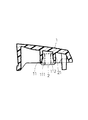
本発明の実施の形態について、図1及び図2を基に説明する。本実施の形態にかかるものは、例えば図1に示す如く、ドア外板の外側に設けられるものであって所定のプラスチック材にて形成されるアウタードアハンドル本体1と、当該アウタードアハンドル本体1の一部に形成されたボス部11に取付けられるインサート金具2と、からなることを基本とするものである。このような基本構成からなるものにおいて、上記アウタードアハンドル本体1は、本実施の形態においては、ポリカーボネイト(PC)、またはポリブチレンテレフタレート(PBT)等の材料が採用されるようになっている。
【0008】
また、このような構成からなるアウタードアハンドル本体1の一部には、図1及び図2に示す如く、ナット等のインサート金具2の取付けられるボス部11が設けられるようになっている。このボス部11の具体的構成は、図2に示す如く、開口端部のところに設けられるものであって所定の内径(D2 )を有するように形成された溶着代(掛り代)がゼロの状態に形成される隙間部112と、当該隙間部112の奥部に形成されるものであって所定の溶着代を有するように内径の値がD1に設定される溶着部111と、からなるものである。なお、このような構成からなるものにおいて、上記隙間部112の、その奥行きの長さ(L)は少なくとも3mm以上の値が採られるようになっている。すなわち、L≧3mmの関係式が成り立つようになっているものである。
【0009】
次に、このような構成からなるボス部11内に装着されるインサート金具2について説明する。このものは、例えば図2に示す如く、その円筒状部の外表面部に所定のローレット部21等を有する金属製の部材からなるものであって、本実施の形態においてはインサートナットが挙げられている。このようなインサートナット(インサート金具)2の上記ローレット部21の外径寸法(d)の値は、ボス部11の溶着部111の内径寸法(D1)よりも大きく、かつ、隙間部112の内径寸法(D2)よりは小さく設定されているものである。すなわち、D1<d≦D2の関係式が成り立つようになっている。具体的には、本実施の形態においては、D1=8.7mm、D2=9.5mm、d=9.1mmに設定されるようになっている。そして、溶着代がゼロの値に設定される隙間部112の長さの値は3mmに設定されるようになっている。
【0010】
このような構成からなるインサートナット(インサート金具)2が所定の温度に加熱された状態で上記ボス部11の内径側に装着されると、上記溶着部111の内表面部が上記インサートナット(インサート金具)2のローレット部21によって溶かされ、上記溶着部111が上記ローレット部21の外表面部に溶着するようになる。一方、このような溶着状態にあって、ボス部11の開口端部側には、長さLの間にわたって隙間部112が設けられるようになっているので、この部分は溶着状態が形成されず、よって、この隙間部112には残留応力が生じないようになる。従って、このようなインサートナット(インサート金具)装着部に、仮にアルカリ性溶剤等が浸入して来たとしても、ボス部11の開口端部(隙間部112)のところにはアルカリ性溶剤による損傷等は発生しないようになる。一般に、例えば、上記プラスチック成形体が車両用のドアハンドルであるような場合、このようなドアハンドル1を有する車両は、その外表面部がさび止め用のワックスにて被われた状態で保管されるとともに、このような車両が顧客に渡されるときには上記防錆用ワックスは所定のアルカリ性溶剤等を用いて取り除かれるようになっており、このときに用いられるアルカリ性溶剤にて上記インサート金具2等の溶着されたボス部開口端部周り(隙間部112)が損傷を受ける場合がある。このようなアルカリ性溶剤による損傷に対して、本実施の形態のものにおいては、上記開口端部(隙間部112)のところに残留応力が生じないようになっているので、何ら問題の生ずることがない。
【0011】
【発明の効果】
本発明によれば、ボス部にインサート金具を有するものであって当該インサート金具の上記ボス部への装着方法が熱溶着手段または圧入手段等にて行われるようにしたボス部にインサート金具を有するプラスチック成形体に関して、上記インサート金具の取り付けられるボス部の開口端部のところに、上記インサート金具が装着されたときに、当該インサート金具の外周部との間に溶着代または圧入代がゼロの値になるように形成された隙間部を設けるようにした構成を採ることとしたので、上記ボス部の開口端部のところには上記インサート金具の装着に起因する残留応力が生じないようになり、このようなボス部開口端部のところに特定の溶剤が付着したとしても、当該ボス部開口端部のところには、上記溶剤による損傷部(破損部)が生じないようになった。
【0012】
また、本発明においては、上記インサート金具の装着されるボス部開口端部に設けられる隙間部を少なくとも開口端面から3mmのところまでは設けるようにした構成を採ることとしたので、インサート金具の装着されるボス部開口端部におけるアルカリ性溶剤による損傷(破損)の発生を抑止することができるようになった。特に、本発明のものにおいては、上記残留応力の存在に基づくアルカリ性溶剤による損傷は、開口端面部において最も著しく生ずるものであるところから、これらを考慮して上記隙間ゼロの部分をボス部の開口端面から少なくとも3mm奥部までは設けるようにし、これによって、開口端部周りには残留応力部を生じさせないようにし、この部分(周り)におけるアルカリ性溶剤による損傷の発生等を効果的に抑止することができるようになった。
【図面の簡単な説明】
【図1】本発明の全体構成を示す横断面図である。
【図2】本発明にかかるボス部及びインサート金具の全体構成を示す展開図である。
【符号の説明】
1 ドアハンドル本体(アウタードアハンドル本体)
11 ボス部
111 溶着部
112 隙間部
2 インサート金具(インサートナット)
21 ローレット部[0001]
BACKGROUND OF THE INVENTION
The present invention relates to a plastic molded body with an insert metal fitting having an insert metal fitting in a part of the plastic molded body, and in particular, the metal fitting is attached at the opening end of a boss portion to which the metal fitting is attached, and the like. A plastic molded body having an insert fitting in which the diameter of the boss portion is set to be large in advance so that residual stress does not occur at the opening end portion of the boss portion when mounted with It is.
[0002]
[Prior art]
In general, when a metal fitting such as an insert nut is attached to a part of a plastic molded body, a boss portion is provided in a part of the plastic molded body and the insert metal fitting is attached to the boss portion via a heat welding means or an adhesive. It is to be mounted by press-fitting means or the like.
[0003]
[Problems to be solved by the invention]
By the way, in the mounting method of the insert fitting to the boss portion as described above, residual stress resulting from the fitting of the fitting is generated around the mounting portion of the boss portion, particularly at the opening end portion thereof. . And when a specific solvent adheres to the place where such residual stress exists, there is a problem that the opening end portion of the boss portion having the residual stress may be damaged by the solvent. . In order to solve such a problem, the boss part is made to take a special shape around the opening end of the boss part to which the insert metal fitting is attached so that no residual stress is generated when the metal fitting is attached. It is an object (problem) of the present invention to provide a plastic molded body having an insert metal fitting.
[0004]
[Means for Solving the Problems]
In order to solve the above problems, the following measures are taken in the present invention. That is, in the first aspect of the present invention, the insert metal fitting is provided in the boss portion having the insert metal fitting in the boss portion, and the mounting method of the insert metal fitting to the boss portion is performed by the heat welding means or the like. In the plastic molded body having the above, the insert fitting is formed in a cylindrical shape, and a cylindrical portion provided with a knurled portion is mainly formed over the entire surface, and the attachment of the insert fitting is provided. When the insert metal fitting is mounted at the open end of the boss portion, the welding allowance or press-fitting allowance is zero between the outer peripheral portion of the cylindrical portion forming the insert metal fitting. a gap portion formed on, over its entire circumference, and, as provided at least 3mm or more predetermined over a length from the boss portion opening end surface And it was decided to adopt a configuration.
[0005]
By adopting such a configuration, in the present invention, the residual stress due to the mounting of the insert fitting is not generated at the opening end portion of the boss portion. Therefore, even if a specific solvent adheres to such a boss portion opening end portion, a damaged portion (broken portion) due to the solvent does not occur at the boss portion opening end portion. Generally, for example, when the plastic molded body is a door handle for a vehicle, the vehicle having such a door handle is stored with its outer surface covered with rust-preventing wax. At the same time, when such a vehicle is delivered to a customer, the rust preventive wax is removed using a predetermined alkaline solvent or the like. The alkaline solvent used at this time may damage the opening end of the boss portion on which the insert fitting or the like is mounted. With respect to the damage caused by such an alkaline solvent, the present invention does not cause any problem because the residual stress is not generated at the opening end portion.
[0006]
Moreover, in this invention, it was decided to take the structure which provided the clearance gap provided in the boss | hub opening end part to which the said insert metal fitting is mounted at least to the place of 3 mm from an opening end surface. By adopting such a configuration, the occurrence of damage (breakage) due to the alkaline solvent at the opening end of the boss portion where the insert fitting is mounted is suppressed. In particular, since the damage due to the alkaline solvent due to the presence of the residual stress is most noticeable in the opening end face portion, in consideration of these, in the present invention, the zero gap portion is the opening of the boss portion. from the end face to at least 3mm deep portion as is provided, whereby, around the open end and to the residual stress does not occur. As a result, it is possible to effectively suppress the occurrence of damage caused by the alkaline solvent in this portion (around).
[0007]
DETAILED DESCRIPTION OF THE INVENTION
An embodiment of the present invention will be described with reference to FIGS. For example, as shown in FIG. 1, an outer door handle
[0008]
Moreover, as shown in FIG.1 and FIG.2, the boss |
[0009]
Next, the
[0010]
When the insert nut (insert metal fitting) 2 having such a configuration is mounted on the inner diameter side of the
[0011]
【The invention's effect】
According to the present invention, the boss portion has the insert metal fitting, and the boss portion has the insert metal fitting attached to the boss portion by the heat welding means or the press-fitting means. With regard to plastic molded products, when the insert fitting is mounted at the open end of the boss portion to which the insert fitting is attached, the welding allowance or press-fitting allowance is zero with the outer periphery of the insert fitting. Since it was decided to adopt a configuration in which a gap portion formed so as to be provided, residual stress due to the mounting of the insert metal fitting does not occur at the opening end portion of the boss portion, Even if a specific solvent adheres to such a boss opening end, a damaged portion (damaged portion) due to the solvent is present at the opening end of the boss. Flip became so no.
[0012]
Further, in the present invention, since the gap portion provided at the opening end portion of the boss portion to which the insert fitting is to be attached is provided at least up to 3 mm from the opening end face, The occurrence of damage (breakage) due to the alkaline solvent at the open end of the boss portion can be suppressed. In particular, in the present invention, the damage due to the alkaline solvent due to the presence of the residual stress occurs most significantly in the opening end surface portion. Provide at least 3 mm deep from the end face, thereby avoiding the generation of residual stress around the end of the opening, and effectively suppressing the occurrence of damage by alkaline solvent in this part (around). Can now.
[Brief description of the drawings]
FIG. 1 is a cross-sectional view showing the overall configuration of the present invention.
FIG. 2 is a development view showing the entire configuration of a boss portion and an insert fitting according to the present invention.
[Explanation of symbols]
1 Door handle body (outer door handle body)
11
21 Knurling
Claims (1)
Priority Applications (1)
| Application Number | Priority Date | Filing Date | Title |
|---|---|---|---|
| JP2002011119A JP4354668B2 (en) | 2002-01-21 | 2002-01-21 | Plastic molded body having an insert metal fitting |
Applications Claiming Priority (1)
| Application Number | Priority Date | Filing Date | Title |
|---|---|---|---|
| JP2002011119A JP4354668B2 (en) | 2002-01-21 | 2002-01-21 | Plastic molded body having an insert metal fitting |
Publications (2)
| Publication Number | Publication Date |
|---|---|
| JP2003213973A JP2003213973A (en) | 2003-07-30 |
| JP4354668B2 true JP4354668B2 (en) | 2009-10-28 |
Family
ID=27648671
Family Applications (1)
| Application Number | Title | Priority Date | Filing Date |
|---|---|---|---|
| JP2002011119A Expired - Fee Related JP4354668B2 (en) | 2002-01-21 | 2002-01-21 | Plastic molded body having an insert metal fitting |
Country Status (1)
| Country | Link |
|---|---|
| JP (1) | JP4354668B2 (en) |
Families Citing this family (4)
| Publication number | Priority date | Publication date | Assignee | Title |
|---|---|---|---|---|
| GB2460092B (en) * | 2008-05-16 | 2011-12-21 | Psm Ip Ltd | An insert kit and installation method |
| US8506027B2 (en) * | 2010-09-29 | 2013-08-13 | General Electric Company | Thermoplastic refrigeration appliance handle with overmolded inserts |
| JP6998195B2 (en) * | 2017-12-14 | 2022-02-04 | Toyo Tire株式会社 | Fastening structure |
| WO2023144965A1 (en) * | 2022-01-27 | 2023-08-03 | ファナック株式会社 | Machine-part mating structure |
-
2002
- 2002-01-21 JP JP2002011119A patent/JP4354668B2/en not_active Expired - Fee Related
Also Published As
| Publication number | Publication date |
|---|---|
| JP2003213973A (en) | 2003-07-30 |
Similar Documents
| Publication | Publication Date | Title |
|---|---|---|
| JP4896679B2 (en) | Hole plug | |
| JPH11190375A (en) | Bush mounting member | |
| JP4354668B2 (en) | Plastic molded body having an insert metal fitting | |
| US8307533B2 (en) | Method of making sealed rolled pole housing for an electric motor | |
| JP2010025087A (en) | Axial fan | |
| EP1457390A1 (en) | Sensor support of a motor vehicle | |
| JP2003291669A (en) | Heat shielding plate mounting structure for fuel tank | |
| JP4410944B2 (en) | Piston consisting of assembled pistons or components welded or soldered together | |
| EP0511061B1 (en) | Plastic objject with alignment inserts | |
| JP2010230164A (en) | Integrated metallic support used for seal for rotating shaft | |
| JPH07259392A (en) | Mounting structure for outside handle for vehicle door | |
| EP0335803B1 (en) | Device to fix logos- or markplates to a box or a carbody | |
| FR2747851A1 (en) | GROUND BOX, IN PARTICULAR FOR ELECTRICAL EQUIPMENT | |
| JP2004278622A (en) | Seal member and seal structure | |
| EP0685655B1 (en) | Resilient fastening clip | |
| JP2002130375A (en) | Vibration isolator | |
| JP3097002B2 (en) | Tips for mounting tappets for internal combustion engines | |
| JPH0559661B2 (en) | ||
| US20070237440A1 (en) | Assembly structure of bearing unit for mounting rotary body to engine cover and assembly method therefor | |
| JPH088007B2 (en) | Vehicle lighting | |
| EP2013048B1 (en) | Strip device comprising an adhesive material, method for fixing same in a vehicle | |
| JP3586014B2 (en) | core | |
| JP2010119631A (en) | Toilet seat | |
| JP3493883B2 (en) | Oil quantity window configuration of cartridge type oil tank | |
| FR2923889A1 (en) | Thermal protection shield for structure of vehicle i.e. motor vehicle, has reflection sheet for covering all or part of surface of body, and fixation unit for fixing shield to structure of vehicle, where unit is molded from piece with body |
Legal Events
| Date | Code | Title | Description |
|---|---|---|---|
| A621 | Written request for application examination |
Free format text: JAPANESE INTERMEDIATE CODE: A621 Effective date: 20041228 |
|
| A977 | Report on retrieval |
Free format text: JAPANESE INTERMEDIATE CODE: A971007 Effective date: 20070914 |
|
| A131 | Notification of reasons for refusal |
Free format text: JAPANESE INTERMEDIATE CODE: A131 Effective date: 20071002 |
|
| A521 | Request for written amendment filed |
Free format text: JAPANESE INTERMEDIATE CODE: A523 Effective date: 20071026 |
|
| A131 | Notification of reasons for refusal |
Free format text: JAPANESE INTERMEDIATE CODE: A131 Effective date: 20081014 |
|
| A521 | Request for written amendment filed |
Free format text: JAPANESE INTERMEDIATE CODE: A523 Effective date: 20081020 |
|
| A131 | Notification of reasons for refusal |
Free format text: JAPANESE INTERMEDIATE CODE: A131 Effective date: 20090609 |
|
| A521 | Request for written amendment filed |
Free format text: JAPANESE INTERMEDIATE CODE: A523 Effective date: 20090622 |
|
| TRDD | Decision of grant or rejection written | ||
| A01 | Written decision to grant a patent or to grant a registration (utility model) |
Free format text: JAPANESE INTERMEDIATE CODE: A01 Effective date: 20090714 |
|
| A01 | Written decision to grant a patent or to grant a registration (utility model) |
Free format text: JAPANESE INTERMEDIATE CODE: A01 |
|
| A61 | First payment of annual fees (during grant procedure) |
Free format text: JAPANESE INTERMEDIATE CODE: A61 Effective date: 20090730 |
|
| R150 | Certificate of patent or registration of utility model |
Ref document number: 4354668 Country of ref document: JP Free format text: JAPANESE INTERMEDIATE CODE: R150 Free format text: JAPANESE INTERMEDIATE CODE: R150 |
|
| FPAY | Renewal fee payment (event date is renewal date of database) |
Free format text: PAYMENT UNTIL: 20120807 Year of fee payment: 3 |
|
| FPAY | Renewal fee payment (event date is renewal date of database) |
Free format text: PAYMENT UNTIL: 20120807 Year of fee payment: 3 |
|
| FPAY | Renewal fee payment (event date is renewal date of database) |
Free format text: PAYMENT UNTIL: 20150807 Year of fee payment: 6 |
|
| R250 | Receipt of annual fees |
Free format text: JAPANESE INTERMEDIATE CODE: R250 |
|
| R250 | Receipt of annual fees |
Free format text: JAPANESE INTERMEDIATE CODE: R250 |
|
| R250 | Receipt of annual fees |
Free format text: JAPANESE INTERMEDIATE CODE: R250 |
|
| R250 | Receipt of annual fees |
Free format text: JAPANESE INTERMEDIATE CODE: R250 |
|
| R250 | Receipt of annual fees |
Free format text: JAPANESE INTERMEDIATE CODE: R250 |
|
| LAPS | Cancellation because of no payment of annual fees |