JP4353337B2 - Information storage device using probe - Google Patents
Information storage device using probe Download PDFInfo
- Publication number
- JP4353337B2 JP4353337B2 JP2008508666A JP2008508666A JP4353337B2 JP 4353337 B2 JP4353337 B2 JP 4353337B2 JP 2008508666 A JP2008508666 A JP 2008508666A JP 2008508666 A JP2008508666 A JP 2008508666A JP 4353337 B2 JP4353337 B2 JP 4353337B2
- Authority
- JP
- Japan
- Prior art keywords
- recording medium
- buffer layer
- thermal buffer
- recording
- thermal
- Prior art date
- Legal status (The legal status is an assumption and is not a legal conclusion. Google has not performed a legal analysis and makes no representation as to the accuracy of the status listed.)
- Expired - Fee Related
Links
Images


Classifications
-
- G—PHYSICS
- G11—INFORMATION STORAGE
- G11B—INFORMATION STORAGE BASED ON RELATIVE MOVEMENT BETWEEN RECORD CARRIER AND TRANSDUCER
- G11B9/00—Recording or reproducing using a method not covered by one of the main groups G11B3/00 - G11B7/00; Record carriers therefor
- G11B9/12—Recording or reproducing using a method not covered by one of the main groups G11B3/00 - G11B7/00; Record carriers therefor using near-field interactions; Record carriers therefor
- G11B9/14—Recording or reproducing using a method not covered by one of the main groups G11B3/00 - G11B7/00; Record carriers therefor using near-field interactions; Record carriers therefor using microscopic probe means, i.e. recording or reproducing by means directly associated with the tip of a microscopic electrical probe as used in Scanning Tunneling Microscopy [STM] or Atomic Force Microscopy [AFM] for inducing physical or electrical perturbations in a recording medium; Record carriers or media specially adapted for such transducing of information
- G11B9/1463—Record carriers for recording or reproduction involving the use of microscopic probe means
- G11B9/149—Record carriers for recording or reproduction involving the use of microscopic probe means characterised by the memorising material or structure
-
- B—PERFORMING OPERATIONS; TRANSPORTING
- B82—NANOTECHNOLOGY
- B82Y—SPECIFIC USES OR APPLICATIONS OF NANOSTRUCTURES; MEASUREMENT OR ANALYSIS OF NANOSTRUCTURES; MANUFACTURE OR TREATMENT OF NANOSTRUCTURES
- B82Y10/00—Nanotechnology for information processing, storage or transmission, e.g. quantum computing or single electron logic
-
- G—PHYSICS
- G11—INFORMATION STORAGE
- G11B—INFORMATION STORAGE BASED ON RELATIVE MOVEMENT BETWEEN RECORD CARRIER AND TRANSDUCER
- G11B9/00—Recording or reproducing using a method not covered by one of the main groups G11B3/00 - G11B7/00; Record carriers therefor
- G11B9/12—Recording or reproducing using a method not covered by one of the main groups G11B3/00 - G11B7/00; Record carriers therefor using near-field interactions; Record carriers therefor
- G11B9/14—Recording or reproducing using a method not covered by one of the main groups G11B3/00 - G11B7/00; Record carriers therefor using near-field interactions; Record carriers therefor using microscopic probe means, i.e. recording or reproducing by means directly associated with the tip of a microscopic electrical probe as used in Scanning Tunneling Microscopy [STM] or Atomic Force Microscopy [AFM] for inducing physical or electrical perturbations in a recording medium; Record carriers or media specially adapted for such transducing of information
- G11B9/1418—Disposition or mounting of heads or record carriers
- G11B9/1427—Disposition or mounting of heads or record carriers with provision for moving the heads or record carriers relatively to each other or for access to indexed parts without effectively imparting a relative movement
- G11B9/1436—Disposition or mounting of heads or record carriers with provision for moving the heads or record carriers relatively to each other or for access to indexed parts without effectively imparting a relative movement with provision for moving the heads or record carriers relatively to each other
-
- H—ELECTRICITY
- H02—GENERATION; CONVERSION OR DISTRIBUTION OF ELECTRIC POWER
- H02K—DYNAMO-ELECTRIC MACHINES
- H02K41/00—Propulsion systems in which a rigid body is moved along a path due to dynamo-electric interaction between the body and a magnetic field travelling along the path
- H02K41/02—Linear motors; Sectional motors
- H02K41/03—Synchronous motors; Motors moving step by step; Reluctance motors
-
- H—ELECTRICITY
- H02—GENERATION; CONVERSION OR DISTRIBUTION OF ELECTRIC POWER
- H02K—DYNAMO-ELECTRIC MACHINES
- H02K7/00—Arrangements for handling mechanical energy structurally associated with dynamo-electric machines, e.g. structural association with mechanical driving motors or auxiliary dynamo-electric machines
- H02K7/14—Structural association with mechanical loads, e.g. with hand-held machine tools or fans
Description
本発明は、例えば走査型プローブメモリーなど、プローブを用いて記録媒体に対し情報の記録または読み取りを行う情報記憶装置に関する。 The present invention relates to an information storage device that records or reads information on a recording medium using a probe, such as a scanning probe memory.
小型で情報を高密度に記録することができる情報記憶装置として、走査型プローブメモリー装置がある。 There is a scanning probe memory device as a small information storage device capable of recording information with high density.
走査型プローブメモリー装置には、トンネル効果を用いたもの、原子間力を用いたもの、磁気力を用いたもの、静電力を用いたもの、非線形誘電率を用いたもの、および記録媒体の熱変形を用いたものなど、様々な種類がある。 Scanning probe memory devices include those that use the tunnel effect, those that use atomic force, those that use magnetic force, those that use electrostatic force, those that use nonlinear dielectric constant, and the heat of the recording medium. There are various types, such as those using deformation.
走査型プローブメモリー装置は、通常、数十ナノメートルないし数マイクロメートル程度の先端径を有するプローブと、表面に記録面が形成された平板状の記録媒体とを備えている。走査型プローブメモリー装置は、プローブの先端を記録媒体の記録面に接近または接触させることにより、記録媒体に対し情報の記録または読み取りを行う。 A scanning probe memory device usually includes a probe having a tip diameter of about several tens of nanometers to several micrometers, and a flat recording medium having a recording surface formed on the surface thereof. The scanning probe memory device records or reads information on a recording medium by bringing the tip of the probe close to or in contact with the recording surface of the recording medium.
また、走査型プローブメモリー装置は、プローブまたは記録媒体を記録面に対し平行な方向に移動させ、プローブと記録媒体との間の位置を変更する。これにより、プローブにより記録媒体の記録面を走査することが可能となり、多量の情報を記録面に高密度に配列することが可能となり、あるいは記録面に配列された多量の情報を連続的にまたはランダムに読み取ることが可能になる。このようなプローブまたは記録媒体の移動には、例えばMEMS(Micro Electro Mechanical System)技術を用いた電磁駆動式または静電駆動式のアクチュエータが用いられる。 Further, the scanning probe memory device moves the probe or the recording medium in a direction parallel to the recording surface, and changes the position between the probe and the recording medium. As a result, the recording surface of the recording medium can be scanned by the probe, and a large amount of information can be arranged on the recording surface with high density, or a large amount of information arranged on the recording surface can be continuously or It becomes possible to read at random. For such movement of the probe or the recording medium, for example, an electromagnetically driven or electrostatically driven actuator using MEMS (Micro Electro Mechanical System) technology is used.
また、走査型プローブメモリー装置の多くは、マルチプローブ方式を採用している。すなわち、走査型プローブメモリー装置の多くは、数十個あるいは数百個、さらには数千個以上のプローブを例えばマトリクス状に配置した2次元プローブアレイを備えている。このようなプローブアレイを用いることにより、多量の情報を記録媒体に迅速に記録することが可能となり、あるいは多量の情報を記録媒体から迅速に読み取ることが可能となる。 Many scanning probe memory devices employ a multi-probe system. That is, many of the scanning probe memory devices include a two-dimensional probe array in which several tens or several hundreds, or even several thousand or more probes are arranged in a matrix, for example. By using such a probe array, a large amount of information can be quickly recorded on the recording medium, or a large amount of information can be quickly read from the recording medium.
ところで、走査型プローブメモリーの小型化を実現するためには、プローブまたは記録媒体記録面に対しを移動させるためのアクチュエータを装置のどこに配置するかを検討する必要がある。 By the way, in order to realize the miniaturization of the scanning probe memory, it is necessary to examine where the actuator for moving the probe or the recording medium with respect to the recording surface is arranged in the apparatus.
一案として、記録媒体とアクチュエータとを記録面に対し平行な方向に並べて配置する構成が考えられる。すなわち、記録媒体とアクチュエータとを記録面に対し平行な方向に並べ、記録面に対し平行な方向に伸びる連結部材で両者を互いに結合する。そして、アクチュエータの駆動により連結部材を記録面に対し平行な方向に引っ張ったり、押し戻したりすることにより、記録媒体を記録面に対し平行な方向に移動させる。一方、プローブは記録媒体の上方に配置し、記録媒体が移動しても動かないようにハウジングなどに固定しておく。これにより、プローブに対し記録媒体を移動させることができ、プローブによる記録面の走査が可能になる。 As one proposal, a configuration in which the recording medium and the actuator are arranged in a direction parallel to the recording surface can be considered. That is, the recording medium and the actuator are arranged in a direction parallel to the recording surface, and are coupled to each other by a connecting member extending in a direction parallel to the recording surface. Then, the recording medium is moved in a direction parallel to the recording surface by pulling or pushing back the connecting member in a direction parallel to the recording surface by driving the actuator. On the other hand, the probe is arranged above the recording medium and fixed to a housing or the like so that it does not move even if the recording medium moves. As a result, the recording medium can be moved relative to the probe, and the recording surface can be scanned by the probe.
しかし、記録媒体とアクチュエータとを記録面に対し平行な方向に並べて配置する構成によれば、記録面に対し平行な面を投影面とした場合におけるプローブメモリー装置の投影面積が大きくなる。 However, according to the configuration in which the recording medium and the actuator are arranged side by side in a direction parallel to the recording surface, the projection area of the probe memory device becomes large when the plane parallel to the recording surface is used as the projection surface.
他方、もう一つの案として、記録媒体とアクチュエータとを記録面に対し垂直な方向に重ねて配置する構成が考えられる。例えば、アクチュエータを組み込んだ平板状の構造体の上に記録媒体を積層する。そして、アクチュエータの駆動により平板状の構造体と記録媒体とが記録面に対し平行な方向に一体的に移動するように構成する。一方、プローブは記録媒体の上方に配置し、記録媒体が移動しても動かないようにハウジングなどに固定しておく。これにより、プローブに対し記録媒体を移動させることができ、プローブによる記録面の走査が可能になる。 On the other hand, as another proposal, a configuration in which the recording medium and the actuator are arranged in a direction perpendicular to the recording surface is conceivable. For example, a recording medium is laminated on a flat plate structure incorporating an actuator. The plate-like structure and the recording medium are integrally moved in a direction parallel to the recording surface by driving the actuator. On the other hand, the probe is arranged above the recording medium and fixed to a housing or the like so that it does not move even if the recording medium moves. As a result, the recording medium can be moved relative to the probe, and the recording surface can be scanned by the probe.
しかし、記録媒体とアクチュエータとを記録面に対し垂直な方向に重ねて配置する構成によると、アクチュエータと記録媒体とが互いに接近して配置される。このため、駆動時にアクチュエータが発する熱が記録媒体に伝導しやすくなる。しかも、アクチュエータにおける熱源は、電磁駆動方式によるアクチュエータであれば主にコイルであり、静電駆動方式によるアクチュエータであれば主に櫛歯電極である。このため、熱の発生は局所的である。この結果、記録媒体の温度分布が不均一となり、記録媒体が不均一に熱膨張するおそれがある。 However, according to the configuration in which the recording medium and the actuator are arranged so as to overlap each other in the direction perpendicular to the recording surface, the actuator and the recording medium are arranged close to each other. For this reason, heat generated by the actuator during driving is easily conducted to the recording medium. Moreover, the heat source in the actuator is mainly a coil if the actuator is based on an electromagnetic drive system, and is mainly a comb electrode if the actuator is based on an electrostatic drive system. For this reason, the heat generation is local. As a result, the temperature distribution of the recording medium becomes non-uniform, and the recording medium may thermally expand non-uniformly.
記録媒体が不均一に熱膨張すると、記録面の平滑性が損なわれ、または記録面に記録された情報の配列が歪むおそれがある。この結果、情報読み取り信号におけるジッタが増加し、情報読み取りの精度が低下するおそれがある。 If the recording medium thermally expands unevenly, the smoothness of the recording surface may be impaired, or the arrangement of information recorded on the recording surface may be distorted. As a result, the jitter in the information reading signal increases and the accuracy of information reading may be reduced.
また、記録媒体の熱変形を用いた走査型プローブメモリー装置は、プローブの先端を加熱し、この加熱した先端を記録媒体の記録面に接触させ、記録面を局所的に熱変形させ、これにより記録面にピットを形成する。このような情報記録原理を有する走査型プローブメモリー装置においては、アクチュエータから発せられた熱の伝導により記録媒体の温度分布が不均一になると、記録面のピット形状にばらつきが生じ、情報の記録が不安定になるおそれがある。 Also, the scanning probe memory device using thermal deformation of the recording medium heats the tip of the probe, contacts the heated tip with the recording surface of the recording medium, and locally heat deforms the recording surface, thereby A pit is formed on the recording surface. In the scanning probe memory device having such an information recording principle, if the temperature distribution of the recording medium becomes non-uniform due to the conduction of heat generated from the actuator, the pit shape on the recording surface varies, and information recording is not possible. May become unstable.
本発明は上記に例示したような問題点に鑑みなされたものであり、本発明の第1の課題は、情報読み取りの精度向上または情報記録の安定性を図ると共に、小型化を実現することができる情報記憶装置を提供することにある。 The present invention has been made in view of the above-described problems, and a first object of the present invention is to improve the accuracy of information reading or to improve the stability of information recording and to achieve downsizing. It is to provide an information storage device that can be used.
本発明の第2の課題は、記録媒体とアクチュエータとを記録面に対し垂直な方向に重ねるように配置しても、アクチュエータから発せられた熱が記録媒体に伝導し、記録媒体における温度分布が不均一になるのを抑制することができる情報記憶装置を提供することにある。 The second problem of the present invention is that even when the recording medium and the actuator are arranged so as to overlap each other in a direction perpendicular to the recording surface, the heat generated from the actuator is conducted to the recording medium, and the temperature distribution in the recording medium is reduced. An object of the present invention is to provide an information storage device capable of suppressing non-uniformity.
上記課題を解決するために本発明の情報記憶装置は、記録面を有する平板状の記録媒体と、前記記録面に対し垂直な方向を上下方向としたときに、前記記録媒体の上方に配置され、前記記録面に対し情報の記録または読み取りを行うプローブと、前記記録媒体の下方に配置され、前記記録媒体を前記記録面に対し平行な方向に移動させるアクチュエータ構造体と、前記記録媒体と前記アクチュエータ構造体との間に配置され、前記アクチュエータ構造体から前記記録媒体への熱の伝導を抑制する第1熱緩衝層とを備えている。 In order to solve the above problems, an information storage device of the present invention is disposed above a recording medium having a recording surface having a recording surface and a vertical direction with respect to the recording surface as a vertical direction. A probe for recording or reading information on the recording surface, an actuator structure disposed below the recording medium and moving the recording medium in a direction parallel to the recording surface, the recording medium, and the recording medium A first thermal buffer layer disposed between the actuator structure and suppressing heat conduction from the actuator structure to the recording medium.
本発明の作用及び他の利得は次に説明する実施形態から明らかにされよう。 The operation and other advantages of the present invention will become apparent from the embodiments described below.
1、50 走査型プローブメモリー装置
21、61 記録媒体
21C、61C 記録面
22、62 アクチュエータ構造体
23、63 第1熱緩衝層
24、64 第2熱緩衝層
25、64 放熱層
31 コイル配線
33、73 プローブ
71 櫛歯電極DESCRIPTION OF
以下、本発明を実施するための最良の形態について実施形態毎に順に図面に基づいて説明する。 Hereinafter, the best mode for carrying out the present invention will be described in order for each embodiment based on the drawings.
(第1実施形態)
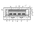
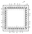
図1は、本発明の情報記憶装置の第1実施形態である走査型プローブメモリー装置の縦断面を示している。図2は、図1中のプローブメモリー装置1を矢示A−A方向から見た横断面を示している。(First embodiment)
FIG. 1 shows a longitudinal section of a scanning probe memory device which is a first embodiment of the information storage device of the present invention. FIG. 2 shows a cross section of the probe memory device 1 in FIG. 1 as viewed from the direction of arrows AA.
図1中の走査型プローブメモリー装置1は、その外形の長さおよび幅(図1中の左右方向の長さ)が例えば数ミリメートルないし数センチメートルであり、厚さ(図1中の上下方向の長さ)が例えば数ミリメートルである小型の装置である。 The scanning probe memory device 1 in FIG. 1 has a length and width (length in the left-right direction in FIG. 1) of, for example, several millimeters to several centimeters, and a thickness (vertical direction in FIG. 1). Is a small device whose length is, for example, several millimeters.
プローブメモリー装置1は、プローブ33を用いて記録媒体21の記録面21C上に情報を高密度に記録することができ、小型であるにもかかわらず、膨大な記憶容量を有する。例えば、その記憶容量は、数十ギガバイトないし数百ギガバイトであり、さらにはテラバイトを超えることも可能である。
The probe memory device 1 can record information with high density on the recording surface 21C of the
プローブメモリー装置1は、記録媒体21の記録面21Cを局所的に熱変形させ、これにより記録面21C上にピットを形成することにより情報を記録する。すなわち、プローブ33の先端に電流を流し、プローブ33の先端を発熱させ、この発熱したプローブ33の先端を記録面21Cに接触させる。これによりプローブ33の先端が接触した部分の記録面21Cが熱変形し、記録面21C上にピットが形成される。
The probe memory device 1 records information by locally deforming the recording surface 21C of the
また、プローブメモリー装置1は、電磁駆動式のアクチュエータを備えており、アクチュエータの駆動により、記録媒体21を記録面21Cに対し平行な方向に移動させることができる。一方、プローブ33は、ハウジング12に固定されている。これにより、プローブ33と記録媒体21との相対位置を変更することができ、プローブ33により記録面21Cを走査することができる。
Further, the probe memory device 1 includes an electromagnetically driven actuator, and the
また、プローブメモリー装置1は、例えば数十個あるいは数百個、さらには数千個以上のプローブ33を例えばマトリクス状に配置した2次元プローブアレイを備えている。これにより、多量の情報を記録面21Cに迅速に記録することができ、あるいは多量の情報を記録面21Cから迅速に読み取ることができる。
Further, the probe memory device 1 includes a two-dimensional probe array in which, for example, several tens or several hundreds, or even several thousand or
図1に示すように、プローブメモリー装置1は、その下部に配置された平板状のハウジング11と、上部に配置されたカップ状のハウジング12とを備えている。ハウジング11とハウジング12との間には空間が形成されている。
As shown in FIG. 1, the probe memory device 1 includes a flat plate-
さらに、プローブメモリー装置1は移動部13を備えている。移動部13は、ハウジング11とハウジング12との間に形成された空間内に配置されている。移動部13の下面(放熱層25の下面)とハウジング11の上面との間には空隙が形成されている。また、移動部13の上面(記録面21C)とハウジング12の下面との間にも空隙が形成されている。さらに、移動部13の各側面は、これに対向するハウジング12の各内側面と離れている。
Further, the probe memory device 1 includes a moving
移動部13は、図2に示すように、4つの支持部14によりハウジング12に支持されている。支持部14は記録面21Cに対し平行な方向に変形することができ、これによりばねとして機能する。支持部14の変形により、移動部13は、ハウジング11とハウジング12との間に形成された空間内において、記録面21Cに対し平行な方向に移動することができる。
As shown in FIG. 2, the moving
移動部13は、図1に示すように、記録媒体21、アクチュエータ構造体22、第1熱緩衝層23、第2熱緩衝層24、放熱層25および絶縁層26を備えている。これらの構成要素は、放熱層25、絶縁層26、アクチュエータ構造体22、第1熱緩衝層23、第2熱緩衝層24および記録媒体21の順序で下から上へ積層されており、互いに隣接する構成要素間は強固に結合している。これにより、これらの構成要素は、記録面21Cに対し平行な方向に一体的に移動することができる。
As shown in FIG. 1, the moving
記録媒体21は平板状の物体である。記録媒体21は、基板21Aおよび記録層21Bを備えている。
The
基板21Aは例えばシリコンにより形成されている。基板21Aの厚さは例えばおよそ10μmである。また、基板21Aの熱伝導率は例えばおよそ168W/(mK)である。
The
記録層21Bは、基板21A上に積層された薄膜である。記録層21Bは例えばポリマー樹脂により形成されている。また、記録層21Bの厚さは例えば1μm以下である。また、記録層21Bの上面が記録面21Cである。加熱したプローブ33の先端を記録面21Cに接触させることにより、記録層21Bが熱変形し、これにより記録面21Cにピットが形成される。
The
なお、記録層21Bの厚さは基板21Aの厚さに比べて十分に薄いため、記録媒体21全体の熱伝導率は基板21Aの熱伝導率に実質的に見て等しい。
Since the
アクチュエータ構造体22は、記録媒体21(移動部13)を記録面21Cに対し平行な方向に移動させる電磁駆動アクチュエータの一部を構成している。アクチュエータ構造体22は、記録媒体21の下方に配置されている。アクチュエータ構造体22は、基板22Aおよびコイル配線31を備えている。
The
基板22Aは例えばSiO2により形成されている。
コイル配線31は例えば銅により形成されている。コイル配線31は、図1に示すように、基板22Aの内部に埋め込まれている。また、コイル配線31は、図2に示すように、螺旋状に形成されている。コイル配線31のピッチPは例えばおよそ500μmである。
The
一方、ハウジング11には永久磁石32が取り付けられている。永久磁石32およびアクチュエータ構造体22により電磁駆動方式のアクチュエータが構成される。コイル配線31に電流を流すことにより、記録媒体21(移動部13)を記録面21Cに対し平行な方向に移動させるための力を作り出すことができる。
On the other hand, a
第1熱緩衝層23は、アクチュエータ構造体22から記録媒体21への熱の伝導を抑制する。第1熱緩衝層23は、図1に示すように、記録媒体21とアクチュエータ22との間に配置されている。第1熱緩衝層23は例えばポリイミド樹脂または紫外線硬化樹脂により形成されている。また、第1熱緩衝層23の厚さはおよそ20μmであることが望ましいが、20μmよりも厚くてもよい。また、第1熱緩衝層23の熱伝導率は、記録媒体21の熱伝導率よりも小さい。具体的には、第1熱緩衝層23の熱伝導率は例えばおよそ0.29W/(mK)である。
The first
第2熱緩衝層24は、第1熱緩衝層23から漏れた熱を拡散する。第2熱緩衝層24は、記録媒体21と第1熱緩衝層23との間に配置されている。第2熱緩衝層24は例えば白金または銅により形成されている。また、第2熱緩衝層24の厚さは1μm以下であることが望ましい。また、第2熱緩衝層24の熱伝導率は、第1熱緩衝層23の熱伝導率よりも大きい。具体的には、第2熱緩衝層24の熱伝導率は例えばおよそ72W/(mK)である。
The second
放熱層25は、アクチュエータ構造体22から発せられる熱を移動部13の下方に逃がす。放熱層25は、アクチュエータ構造体22の下方に配置されている。放熱層25は熱抵抗が小さい材料、例えば銅により形成されている。また、放熱層25の厚さは例えばおよそ10μmである。また、放熱層25とアクチュエータ構造体22との間には、コイル配線23と放熱層25と間を電気的に絶縁するための絶縁層26が設けられている。また、各支持部14は放熱層25に接続されている。
The
プローブ33は、記録媒体21の上方に配置され、記録面21Cに対し情報の記録または読み取りを行う。プローブ33の先端径は例えばおよそ50nmである。
The
図3は移動部13の縦断面の一部を拡大して示している。これより、図3を用い、第1熱緩衝層23および第2熱緩衝層24の熱緩衝作用、並びに放熱層25の放熱作用について説明する。
FIG. 3 shows an enlarged part of the longitudinal section of the moving
移動部13を記録面21Cに対し平行な方向に移動させるために、アクチュエータを駆動する。アクチュエータを駆動するとき、コイル配線31に電流を流す。コイル配線31に電流を流すことにより、コイル配線31は熱を発する。コイル配線31のピッチは例えば500μmであるため、熱の発生は局所的である。
In order to move the moving
コイル配線31から発せられた熱の一部は、アクチュエータ構造体22の基板22A内部を伝導し、アクチュエータ構造体22の上方に向かって進む。
A part of the heat generated from the
アクチュエータ構造体22上には第1熱緩衝層23が配置されている。第1熱緩衝層23は上述したように熱伝導率が小さい。したがって、アクチュエータ構造体22の上方に向かって進む熱の大部分は第1熱緩衝層23により遮られる。
A first
アクチュエータ構造体22の上方に向かって進む熱の大部分は第1熱緩衝層23により遮られるものの、この熱の一部は第1熱緩衝層23を貫いて伝導し、第1熱緩衝層23の上方に漏れる。
Although most of the heat traveling upward of the
第1熱緩衝層23上には第2熱緩衝層24が配置されている。第2熱緩衝層24は上述したように熱伝導率が第1熱緩衝層23の熱伝導率よりも大きい。したがって、第1熱緩衝層23から漏れた熱は第2熱緩衝24において拡散する。すなわち、たとえコイル配線23から発せられた熱の一部が第1熱緩衝層23内を局所的に伝導してきたとしても、この局所的な熱は第2熱緩衝層24において記録面21Cに対しほぼ平行な方向に広範囲に広がる。
A second
第2熱緩衝層24において拡散した熱が記録媒体21に伝導することがある。第2熱緩衝層24において拡散した熱が記録媒体21に伝導すると、記録媒体21の温度が上がる。しかし、コイル配線23から発せられた熱の大部分は、第1熱緩衝層23によって遮られているので、記録媒体21の温度上昇の程度は小さい。さらに、第1熱緩衝層23から漏れた熱は、第2熱緩衝層24により拡散されているので、記録媒体21の温度分布はほぼ均一である。
The heat diffused in the second
一方、コイル配線23から発せられた熱の一部はアクチュエータ構造体22の下方に向かって伝導する。
On the other hand, a part of the heat generated from the
アクチュエータ構造体22下には放熱層25が配置されている。放熱層25は上述したように熱抵抗が小さい。これにより、アクチュエータ構造体22の下方に向かって伝導する熱は放熱層25により移動部13の下方に逃げる。また、各支持部14は放熱層25に接続されている。これにより、放熱層25に伝導した熱は各支持部14を通じてハウジング12側に向かって逃げる。この結果、コイル配線31から発せられ記録媒体21に向かって伝導する熱の量が減り、それゆえ記録媒体21の温度上昇の程度がより一層小さくなる。
A
以上説明したとおり、プローブメモリー装置1は、アクチュエータ構造体22と記録媒体21との間に配置された第1熱緩衝層23を有している。これにより、アクチュエータ構造体22において局所的に発せられた熱がアクチュエータ構造体22から記録媒体21に伝わるのを抑制することができる。
As described above, the probe memory device 1 has the first
したがって、アクチュエータ構造体22と記録媒体21とを記録面21Cに対し垂直な方向に重ねるように配置しても、アクチュエータの駆動時に記録媒体21の温度分布が不均一になるのを抑制することができる。つまり、アクチュエータ構造体22と記録媒体21とを重ねるように配置することによりアクチュエータ構造体22と記録媒体21とをきわめて接近させても、記録媒体21の温度分布が不均一になるのを抑制することができる。
Therefore, even if the
これにより、記録面21Cに対し平行な面を投影面とした場合におけるプローブメモリー装置1の投影面積を小さくすることができ、プローブメモリー装置1の小型化を図ることができる。 Thereby, the projection area of the probe memory device 1 can be reduced when a plane parallel to the recording surface 21C is used as the projection surface, and the probe memory device 1 can be downsized.
これと同時に、記録媒体21の不均一な熱膨張を抑制することができ、情報読み取り信号におけるジッタを減少させ、情報の読み取りの精度を向上させることができる。
At the same time, non-uniform thermal expansion of the
さらに、記録媒体21の温度分布の不均一により、記録面21Cに形成されるピットの形状が不均一となるのを抑制することができ、情報記録の安定性を図ることができる。
Furthermore, nonuniformity of the temperature distribution of the
そして、これらの効果は、第1熱緩衝層23の熱伝導率を記録媒体21の熱伝導率よりも小さくすることにより、より一層大きくなる。
These effects are further increased by making the thermal conductivity of the first
さらに、第1熱緩衝層23の熱伝導率を小さくすることにより、第1熱緩衝層23の厚さを薄くすることができ、プローブメモリー装置1の薄型化を図ることができる。
Furthermore, by reducing the thermal conductivity of the first
また、プローブメモリー装置1は、第1熱緩衝層23と記録媒体21との間に配置された第2熱緩衝層24を有している。そして、第2熱緩衝層24の熱伝導率は、第1熱緩衝層23の熱伝導率よりも大きい。これにより、第1熱緩衝層23から漏れて記録媒体21に向かって進む熱を拡散することができる。したがって、記録媒体21の温度分布が不均一になるのを抑制することができる。記録媒体21の温度分布の不均一を抑制する効果は、第1熱緩衝層23だけを設けた場合よりも、第1熱緩衝層23と第2熱緩衝層24とを設けた場合の方が大きい。
The probe memory device 1 also has a second
また、プローブメモリー装置1は、アクチュエータ構造体22の下方に配置され、アクチュエータ構造体22が発する熱を放熱する放熱層25を備えている。これにより、アクチュエータ構造体22から発せられた熱をアクチュエータ構造体22の下方に逃がすことができる。したがって、アクチュエータ構造体22から発せられ記録媒体21へ向けて伝導する熱の量を減らすことができる。
The probe memory device 1 includes a
(第2実施形態)
図4は、本発明の情報記憶装置の第2実施形態である走査型プローブメモリー装置の縦断面を示している。図5は、図4中のプローブメモリー装置1を矢示B−B方向から見た横断面を示している。(Second Embodiment)
FIG. 4 shows a longitudinal section of a scanning probe memory device which is a second embodiment of the information storage device of the present invention. FIG. 5 shows a cross section of the probe memory device 1 in FIG. 4 as viewed from the direction of arrows BB.
図4中のプローブメモリー装置50は、図1中のプローブメモリー装置1と同様に、小型であるにもかかわらず、膨大な記憶容量を有する。また、プローブメモリー装置50は、プローブメモリー装置1と同様に、ポリマー樹脂から形成された記録面61Cに、加熱されたプローブ73の先端を接触させ、これによりピットを形成することによって情報を記録する方式を採用している。
Similar to the probe memory device 1 in FIG. 1, the
一方、プローブメモリー装置50は、プローブメモリー装置50と異なり、静電駆動式のアクチュエータを備えている。
On the other hand, unlike the
図4に示すように、プローブメモリー装置50のハウジング51とハウジング52との間の空間には、移動部53が配置されている。移動部53は、支持部54により、記録面61Cに対し平行な方向に移動可能な状態で支持されている。
As shown in FIG. 4, a moving
移動部53は、記録媒体61、アクチュエータ構造体62、第1熱緩衝層63、第2熱緩衝層64、放熱層65および絶縁層66を備えている。これらの構成要素は、放熱層65、絶縁層66、アクチュエータ構造体62、第1熱緩衝層63、第2熱緩衝層64および記録媒体61の順序で下から上へ積層されており、記録面61Cに対し平行な方向に一体的に移動することができる。
The moving
記録媒体61、第1熱緩衝層63、第2熱緩衝層64、放熱層65および絶縁層66は、図1中の記録媒体21、第1熱緩衝層23、第2熱緩衝層24、放熱層25および絶縁層26とそれぞれほぼ同じである。
The
アクチュエータ構造体62は、記録媒体61(移動部53)を記録面61Cに対し平行な方向に移動させる静電駆動アクチュエータの一部を構成している。アクチュエータ構造体62は、記録媒体61の下方に配置されている。アクチュエータ構造体62は、基板62Aおよび櫛歯電極71を備えている。
The
櫛歯電極71は、図5に示すように、基板62Aの周囲に形成されている。一方、ハウジング12の内側面には櫛歯電極72が形成されている。櫛歯電極71と櫛歯電極72とは、空隙を介して噛み合っている。櫛歯電極71と櫛歯電極72との間に電界を形成することにより、記録媒体61(移動部53)を記録面61Cに対し平行な方向に移動させるための力を作り出すことができる。
As shown in FIG. 5, the
このような構成を有するプローブメモリー装置50によっても、プローブメモリー装置1と同様の効果を得ることができる。
Also with the
すなわち、櫛歯電極71と記録媒体61とを重ねるように配置することにより櫛歯電極71と記録媒体61とをきわめて接近させても、記録媒体61の温度分布が不均一になるのを抑制することができる。したがって、プローブメモリー装置50の小型化を図ることができると共に、情報の読み取りの精度を向上させ、かつ情報記録の安定性を図ることができる。
That is, by arranging the
なお、図1中のプローブメモリー装置1において、記録面21Cに対し平行な方向における第1熱緩衝層23の面の面積は、アクチュエータ構造体22の上面の面積、あるいは記録媒体21の下面の面積とほぼ等しい。つまり、第1熱緩衝層22は、アクチュエータ構造体22の上面上に全面的に積層されている。そして、第2熱緩衝層24も第1熱緩衝層23の上面上に全面的に積層されている。これにより、記録媒体21、第1熱緩衝層23、第2熱緩衝層24およびアクチュエータ構造体22の製造の容易化を図ることができる。
In the probe memory device 1 in FIG. 1, the area of the surface of the first
例えば、アクチュエータ構造体22の基板22Aの材料、第1熱緩衝層23の材料、第2熱緩衝層24の材料および記録媒体21の材料が予め積層された広い面積を有する多層平板材料を用意する。そして、この多層平板材料から、記録媒体21の上面形状に等しい形状を有するブロックを切り出す。このような簡単な工程を行うだけで、記録媒体21、第1熱緩衝層23、第2熱緩衝層24およびアクチュエータ構造体22の基板22Aからなる構造体を作り出すことが可能になる。
For example, a multilayer flat plate material having a large area in which the material of the
もっとも、アクチュエータ構造体22のコイル配線31が形成されている領域に対応する領域だけに第1熱緩衝層を配置してもよい。
But you may arrange | position a 1st heat buffer layer only to the area | region corresponding to the area | region in which the
同様に、図4中のプローブメモリー装置50でも、第1熱緩衝層63および第2熱緩衝層64を記録媒体61の下面に対応するように全面的に形成することにより、記録媒体61、第1熱緩衝層63、第2熱緩衝層64およびアクチュエータ構造体62の基板62Aからなる構造体を容易に作り出すことが可能になる。もっとも、櫛歯電極71が形成されている領域に対応する領域だけに第1熱緩衝層を配置してもよい。
Similarly, in the
第1熱緩衝層23、63の材料および厚さは上述した具体例に限定されない。もっとも、第1熱緩衝層23、63の材料および厚さは、コイル31または櫛歯電極71から発せられる熱エネルギーの大きさ、第1熱緩衝層23、63の熱抑制効果の大きさ、記録媒体21、61の熱伝導率、記録媒体21、61の温度分布の不均一が情報の記録・読み取りに与える影響の程度、プローブメモリー装置1、50の薄型化の要請などを考慮して決めることが望ましい。第2熱緩衝層24、64の材料および厚さについても同様である。
The material and thickness of the first heat buffer layers 23 and 63 are not limited to the specific examples described above. However, the material and thickness of the first thermal buffer layers 23 and 63 are the magnitude of the thermal energy emitted from the
また、第1熱緩衝層23、63に、熱抵抗値が小さい材料を用いる場合には、第1熱緩衝層23,63の厚さを厚くする。例えば第1熱緩衝層23、63に熱伝導率3.0W/cmKのSiCを用いた場合には第1熱緩衝層23、63の厚さを90μm以上にする。このような構成によっても、記録媒体21、61の温度分布の不均一性を緩和することができる。
Further, when a material having a small thermal resistance value is used for the first thermal buffer layers 23 and 63, the thickness of the first thermal buffer layers 23 and 63 is increased. For example, when SiC having a thermal conductivity of 3.0 W / cmK is used for the first thermal buffer layers 23 and 63, the thickness of the first thermal buffer layers 23 and 63 is set to 90 μm or more. Even with such a configuration, the non-uniformity of the temperature distribution of the
また、プローブメモリー装置1、50では、アクチュエータ構造体22上に、熱伝導率の小さい第1熱緩衝層23、63を配置し、第1熱緩衝層23、63上に、熱伝導率の大きい第2熱緩衝層24、64を配置する場合を例にあげた。しかし、本発明はこれに限られない。アクチュエータ構造体22上に、熱伝導率の大きい熱緩衝層を配置し、この熱緩衝層上に、熱伝導率の小さい別の熱緩衝層を配置してもよい。まず熱源の近くで熱を拡散し、続いて拡散された熱の伝導を抑制する。これにより、記録媒体の温度の上昇を抑えつつ、温度分布の均一化を図ることができる。
In the
あるいは、アクチュエータ構造体22上に、熱伝導率の大きい熱緩衝層を配置し、この熱緩衝層上に、熱伝導率の小さい別の熱緩衝層を配置し、さらに当該別の熱緩衝層上に、熱伝導率の大きいさらに別の熱緩衝層を配置するといった3層構造としてもよい。まず熱源の近くで熱を拡散し、続いて拡散された熱の伝導を抑制し、続いて記録媒体の直下で熱をさらに拡散する。このような構成によっても、記録媒体の温度の上昇を抑えつつ、温度分布の均一化を図ることができる。
Alternatively, a thermal buffer layer having a high thermal conductivity is disposed on the
また、第1熱緩衝層を、記録媒体とアクチュエータ構造体とを接着する接着材料により形成してもよい。これにより、接着層と熱緩衝層とを単一の層によって構成することができる。この構成は、プローブメモリー装置の薄型化に貢献する。 The first heat buffer layer may be formed of an adhesive material that bonds the recording medium and the actuator structure. Thereby, a contact bonding layer and a heat buffer layer can be comprised by a single layer. This configuration contributes to reducing the thickness of the probe memory device.
また、上述した説明では、記録面を熱変形させることにより情報を記録する方式の走査型プローブメモリー装置を例にあげたが、本発明はこれに限られない。本発明は、例えば、SNDM(Scanning Nonlinear Dielectric Microscopy)方式の走査型プローブメモリー装置にも適用することができる。この場合、強誘電体材料から形成された記録層を有する記録媒体を用い、記録層の直下には電極を配置する。 In the above description, the scanning probe memory device that records information by thermally deforming the recording surface is taken as an example, but the present invention is not limited to this. The present invention can also be applied to, for example, an SNDM (Scanning Nonlinear Dielectric Microscopy) scanning probe memory device. In this case, a recording medium having a recording layer formed of a ferroelectric material is used, and an electrode is disposed immediately below the recording layer.
また、この場合、第1熱緩衝層上に配置された第2熱緩衝層を、記録媒体の電極の材料により形成してもよい。これにより、電極と熱緩衝層とを単一の層によって構成することができる。この構成は、プローブメモリー装置の薄型化に貢献する。 In this case, the second thermal buffer layer disposed on the first thermal buffer layer may be formed of a material for the electrode of the recording medium. Thereby, an electrode and a heat buffer layer can be comprised by a single layer. This configuration contributes to reducing the thickness of the probe memory device.
また、本発明は、請求の範囲および明細書全体から読み取るこのできる発明の要旨または思想に反しない範囲で適宜変更可能であり、そのような変更を伴う情報記憶装置もまた本発明の技術思想に含まれる。 The present invention can be appropriately changed without departing from the gist or idea of the invention that can be read from the claims and the entire specification, and an information storage device accompanying such a change is also included in the technical idea of the invention. included.
本発明に係るプローブを用いた情報記憶装置は、例えば走査型プローブメモリー装置など、プローブを用いて記録媒体に対し情報の記録または読み取りを行う情報記憶装置に利用可能である。 The information storage device using the probe according to the present invention can be used for an information storage device that records or reads information on a recording medium using a probe, such as a scanning probe memory device.
Claims (7)
前記記録面に対し垂直な方向を上下方向としたときに、前記記録媒体の上方に配置され、前記記録面に対し情報の記録または読み取りを行うプローブと、
前記記録媒体の下方に配置され、前記記録媒体を前記記録面に対し平行な方向に移動させるアクチュエータ構造体と、
前記記録媒体と前記アクチュエータ構造体との間に配置され、前記アクチュエータ構造体から前記記録媒体への熱の伝導を抑制する第1熱緩衝層と
を備え、
前記第1熱緩衝層の熱伝導率は、前記記録媒体の熱伝導率よりも小さい
ことを特徴とする情報記憶装置。A flat recording medium having a recording surface;
A probe that is arranged above the recording medium and records or reads information on the recording surface when the direction perpendicular to the recording surface is the vertical direction;
An actuator structure disposed below the recording medium and moving the recording medium in a direction parallel to the recording surface;
A first thermal buffer layer disposed between the recording medium and the actuator structure and suppressing conduction of heat from the actuator structure to the recording medium;
Equipped with a,
The thermal conductivity of the first thermal buffer layer is smaller than the thermal conductivity of the recording medium.
An information storage device.
前記第2熱緩衝層の熱伝導率は、前記第1熱緩衝層の熱伝導率よりも大きいことを特徴とする請求項1に記載の情報記憶装置。A second thermal buffer layer disposed between the recording medium and the first thermal buffer layer;
The information storage device according to claim 1, wherein the thermal conductivity of the second thermal buffer layer is greater than the thermal conductivity of the first thermal buffer layer.
前記第3熱緩衝層の熱伝導率は、前記第1熱緩衝層の熱伝導率よりも大きいことを特徴とする請求項1に記載の情報記憶装置。A third thermal buffer layer disposed between the actuator structure and the first thermal buffer layer;
The information storage device according to claim 1, wherein the thermal conductivity of the third thermal buffer layer is greater than the thermal conductivity of the first thermal buffer layer.
Applications Claiming Priority (3)
| Application Number | Priority Date | Filing Date | Title |
|---|---|---|---|
| JP2006095473 | 2006-03-30 | ||
| JP2006095473 | 2006-03-30 | ||
| PCT/JP2007/057144 WO2007114353A1 (en) | 2006-03-30 | 2007-03-30 | Information storage device using probe |
Publications (2)
| Publication Number | Publication Date |
|---|---|
| JPWO2007114353A1 JPWO2007114353A1 (en) | 2009-08-20 |
| JP4353337B2 true JP4353337B2 (en) | 2009-10-28 |
Family
ID=38563621
Family Applications (1)
| Application Number | Title | Priority Date | Filing Date |
|---|---|---|---|
| JP2008508666A Expired - Fee Related JP4353337B2 (en) | 2006-03-30 | 2007-03-30 | Information storage device using probe |
Country Status (4)
| Country | Link |
|---|---|
| US (1) | US7945963B2 (en) |
| EP (1) | EP2009629A4 (en) |
| JP (1) | JP4353337B2 (en) |
| WO (1) | WO2007114353A1 (en) |
Families Citing this family (1)
| Publication number | Priority date | Publication date | Assignee | Title |
|---|---|---|---|---|
| JP2008146798A (en) * | 2006-12-13 | 2008-06-26 | Hitachi Global Storage Technologies Netherlands Bv | Magnetic head slider |
Family Cites Families (8)
| Publication number | Priority date | Publication date | Assignee | Title |
|---|---|---|---|---|
| JP3029499B2 (en) | 1992-05-07 | 2000-04-04 | キヤノン株式会社 | Recording and playback device |
| US6411589B1 (en) | 1998-07-29 | 2002-06-25 | Hewlett-Packard Company | System and method for forming electrostatically actuated data storage mechanisms |
| EP1168334B1 (en) * | 2000-06-26 | 2006-03-08 | Samsung Electronics Co. Ltd. | Electromagnetic X-Y stage driver for nano data storage system and method for fabricating coils of the same |
| JP2005063511A (en) * | 2003-08-08 | 2005-03-10 | Konica Minolta Opto Inc | Optical head |
| US7379412B2 (en) * | 2004-04-16 | 2008-05-27 | Nanochip, Inc. | Methods for writing and reading highly resolved domains for high density data storage |
| FR2870037B1 (en) * | 2004-05-04 | 2006-07-14 | Commissariat Energie Atomique | INFORMATION RECORDING SYSTEM AND METHOD OF USING SUCH A SYSTEM |
| JP4097632B2 (en) * | 2004-06-30 | 2008-06-11 | 株式会社日立製作所 | Multi-probe storage device |
| US7869162B2 (en) * | 2007-02-16 | 2011-01-11 | Seagate Technology Llc | Thin film structure with controlled lateral thermal spreading in the thin film |
-
2007
- 2007-03-30 US US12/295,022 patent/US7945963B2/en not_active Expired - Fee Related
- 2007-03-30 JP JP2008508666A patent/JP4353337B2/en not_active Expired - Fee Related
- 2007-03-30 EP EP07740580A patent/EP2009629A4/en not_active Withdrawn
- 2007-03-30 WO PCT/JP2007/057144 patent/WO2007114353A1/en active Application Filing
Also Published As
| Publication number | Publication date |
|---|---|
| JPWO2007114353A1 (en) | 2009-08-20 |
| EP2009629A4 (en) | 2009-05-27 |
| US20090178167A1 (en) | 2009-07-09 |
| EP2009629A1 (en) | 2008-12-31 |
| US7945963B2 (en) | 2011-05-17 |
| WO2007114353A1 (en) | 2007-10-11 |
Similar Documents
| Publication | Publication Date | Title |
|---|---|---|
| JP2007287277A (en) | Magnetic head slider and head gimbal assembly | |
| JP5055646B2 (en) | Information recording / reproducing device | |
| JP5055641B2 (en) | Information recording / reproducing device | |
| JP4353337B2 (en) | Information storage device using probe | |
| JP5246688B2 (en) | Information recording / reproducing device | |
| EP2003645A1 (en) | Information storage device using probe | |
| US20090285082A1 (en) | Electric field read/write head, method of manufacturing the electric field read/write head, and information storage device including the electric field read/write head | |
| JP2007132922A (en) | Semiconductor probe and recording and reproducing method | |
| JP3817521B2 (en) | Mechanical data processing | |
| JP4099066B2 (en) | Data read / write system | |
| US8576516B2 (en) | Magnetic disc apparatus including a thermal actuator as part of a two-stage actuator | |
| JP4898436B2 (en) | Data recording method and apparatus with deformable memory support for carrying out this method | |
| KR100623028B1 (en) | The Header of Microscope Nano-data-storage packaging Z-axis Operating System using Static Electricity Force | |
| Yang et al. | Probe recording technology using novel MEMS devices | |
| JP2008052882A (en) | Magnetic head | |
| JP5553302B2 (en) | Near-field optical head manufacturing method, near-field optical head, and information recording / reproducing apparatus | |
| Yang et al. | Improved design of polymeric composite electrothermal micro-actuator for high track density hard disk drives | |
| Chen et al. | Integrated fabrication of electrostatic microactuator for HDD R/W head positioning | |
| JP5334203B2 (en) | Near-field optical head and information recording / reproducing apparatus | |
| WO2009154043A1 (en) | Head gimbal assembly with optical guide structure, and information recording/reproducing device | |
| JP5611590B2 (en) | Near-field optical head and information recording / reproducing apparatus | |
| KR100746769B1 (en) | Cantilever for storaging data, data storage device having the cantilever and method for manufacturing the same | |
| JP5263879B2 (en) | Pivot bearing and information recording / reproducing apparatus | |
| JP2004213849A (en) | Device and method for recording information, and device and method for reproducing information | |
| KR20060124078A (en) | Spm information storage system using piezoelectric material and data recording method thereof |
Legal Events
| Date | Code | Title | Description |
|---|---|---|---|
| TRDD | Decision of grant or rejection written | ||
| A01 | Written decision to grant a patent or to grant a registration (utility model) |
Free format text: JAPANESE INTERMEDIATE CODE: A01 Effective date: 20090714 |
|
| A01 | Written decision to grant a patent or to grant a registration (utility model) |
Free format text: JAPANESE INTERMEDIATE CODE: A01 |
|
| A61 | First payment of annual fees (during grant procedure) |
Free format text: JAPANESE INTERMEDIATE CODE: A61 Effective date: 20090721 |
|
| R150 | Certificate of patent or registration of utility model |
Free format text: JAPANESE INTERMEDIATE CODE: R150 |
|
| FPAY | Renewal fee payment (event date is renewal date of database) |
Free format text: PAYMENT UNTIL: 20120807 Year of fee payment: 3 |
|
| LAPS | Cancellation because of no payment of annual fees |