JP4352903B2 - Single-shaft multistage pump - Google Patents
Single-shaft multistage pump Download PDFInfo
- Publication number
- JP4352903B2 JP4352903B2 JP2004007907A JP2004007907A JP4352903B2 JP 4352903 B2 JP4352903 B2 JP 4352903B2 JP 2004007907 A JP2004007907 A JP 2004007907A JP 2004007907 A JP2004007907 A JP 2004007907A JP 4352903 B2 JP4352903 B2 JP 4352903B2
- Authority
- JP
- Japan
- Prior art keywords
- water
- bearing
- shaft
- rotating shaft
- balance
- Prior art date
- Legal status (The legal status is an assumption and is not a legal conclusion. Google has not performed a legal analysis and makes no representation as to the accuracy of the status listed.)
- Expired - Fee Related
Links
Images


Classifications
-
- F—MECHANICAL ENGINEERING; LIGHTING; HEATING; WEAPONS; BLASTING
- F04—POSITIVE - DISPLACEMENT MACHINES FOR LIQUIDS; PUMPS FOR LIQUIDS OR ELASTIC FLUIDS
- F04D—NON-POSITIVE-DISPLACEMENT PUMPS
- F04D1/00—Radial-flow pumps, e.g. centrifugal pumps; Helico-centrifugal pumps
- F04D1/06—Multi-stage pumps
- F04D1/063—Multi-stage pumps of the vertically split casing type
-
- F—MECHANICAL ENGINEERING; LIGHTING; HEATING; WEAPONS; BLASTING
- F04—POSITIVE - DISPLACEMENT MACHINES FOR LIQUIDS; PUMPS FOR LIQUIDS OR ELASTIC FLUIDS
- F04D—NON-POSITIVE-DISPLACEMENT PUMPS
- F04D29/00—Details, component parts, or accessories
- F04D29/02—Selection of particular materials
- F04D29/026—Selection of particular materials especially adapted for liquid pumps
-
- F—MECHANICAL ENGINEERING; LIGHTING; HEATING; WEAPONS; BLASTING
- F04—POSITIVE - DISPLACEMENT MACHINES FOR LIQUIDS; PUMPS FOR LIQUIDS OR ELASTIC FLUIDS
- F04D—NON-POSITIVE-DISPLACEMENT PUMPS
- F04D29/00—Details, component parts, or accessories
- F04D29/04—Shafts or bearings, or assemblies thereof
- F04D29/041—Axial thrust balancing
- F04D29/0416—Axial thrust balancing balancing pistons
-
- F—MECHANICAL ENGINEERING; LIGHTING; HEATING; WEAPONS; BLASTING
- F04—POSITIVE - DISPLACEMENT MACHINES FOR LIQUIDS; PUMPS FOR LIQUIDS OR ELASTIC FLUIDS
- F04D—NON-POSITIVE-DISPLACEMENT PUMPS
- F04D29/00—Details, component parts, or accessories
- F04D29/04—Shafts or bearings, or assemblies thereof
- F04D29/046—Bearings
- F04D29/047—Bearings hydrostatic; hydrodynamic
-
- F—MECHANICAL ENGINEERING; LIGHTING; HEATING; WEAPONS; BLASTING
- F04—POSITIVE - DISPLACEMENT MACHINES FOR LIQUIDS; PUMPS FOR LIQUIDS OR ELASTIC FLUIDS
- F04D—NON-POSITIVE-DISPLACEMENT PUMPS
- F04D29/00—Details, component parts, or accessories
- F04D29/08—Sealings
- F04D29/10—Shaft sealings
- F04D29/12—Shaft sealings using sealing-rings
- F04D29/126—Shaft sealings using sealing-rings especially adapted for liquid pumps
-
- F—MECHANICAL ENGINEERING; LIGHTING; HEATING; WEAPONS; BLASTING
- F16—ENGINEERING ELEMENTS AND UNITS; GENERAL MEASURES FOR PRODUCING AND MAINTAINING EFFECTIVE FUNCTIONING OF MACHINES OR INSTALLATIONS; THERMAL INSULATION IN GENERAL
- F16J—PISTONS; CYLINDERS; SEALINGS
- F16J15/00—Sealings
- F16J15/16—Sealings between relatively-moving surfaces
-
- F—MECHANICAL ENGINEERING; LIGHTING; HEATING; WEAPONS; BLASTING
- F05—INDEXING SCHEMES RELATING TO ENGINES OR PUMPS IN VARIOUS SUBCLASSES OF CLASSES F01-F04
- F05D—INDEXING SCHEME FOR ASPECTS RELATING TO NON-POSITIVE-DISPLACEMENT MACHINES OR ENGINES, GAS-TURBINES OR JET-PROPULSION PLANTS
- F05D2210/00—Working fluids
- F05D2210/10—Kind or type
- F05D2210/11—Kind or type liquid, i.e. incompressible
-
- F—MECHANICAL ENGINEERING; LIGHTING; HEATING; WEAPONS; BLASTING
- F05—INDEXING SCHEMES RELATING TO ENGINES OR PUMPS IN VARIOUS SUBCLASSES OF CLASSES F01-F04
- F05D—INDEXING SCHEME FOR ASPECTS RELATING TO NON-POSITIVE-DISPLACEMENT MACHINES OR ENGINES, GAS-TURBINES OR JET-PROPULSION PLANTS
- F05D2240/00—Components
- F05D2240/50—Bearings
- F05D2240/53—Hydrodynamic or hydrostatic bearings
-
- F—MECHANICAL ENGINEERING; LIGHTING; HEATING; WEAPONS; BLASTING
- F05—INDEXING SCHEMES RELATING TO ENGINES OR PUMPS IN VARIOUS SUBCLASSES OF CLASSES F01-F04
- F05D—INDEXING SCHEME FOR ASPECTS RELATING TO NON-POSITIVE-DISPLACEMENT MACHINES OR ENGINES, GAS-TURBINES OR JET-PROPULSION PLANTS
- F05D2240/00—Components
- F05D2240/55—Seals
-
- F—MECHANICAL ENGINEERING; LIGHTING; HEATING; WEAPONS; BLASTING
- F16—ENGINEERING ELEMENTS AND UNITS; GENERAL MEASURES FOR PRODUCING AND MAINTAINING EFFECTIVE FUNCTIONING OF MACHINES OR INSTALLATIONS; THERMAL INSULATION IN GENERAL
- F16C—SHAFTS; FLEXIBLE SHAFTS; ELEMENTS OR CRANKSHAFT MECHANISMS; ROTARY BODIES OTHER THAN GEARING ELEMENTS; BEARINGS
- F16C2208/00—Plastics; Synthetic resins, e.g. rubbers
- F16C2208/20—Thermoplastic resins
-
- F—MECHANICAL ENGINEERING; LIGHTING; HEATING; WEAPONS; BLASTING
- F16—ENGINEERING ELEMENTS AND UNITS; GENERAL MEASURES FOR PRODUCING AND MAINTAINING EFFECTIVE FUNCTIONING OF MACHINES OR INSTALLATIONS; THERMAL INSULATION IN GENERAL
- F16C—SHAFTS; FLEXIBLE SHAFTS; ELEMENTS OR CRANKSHAFT MECHANISMS; ROTARY BODIES OTHER THAN GEARING ELEMENTS; BEARINGS
- F16C2360/00—Engines or pumps
- F16C2360/44—Centrifugal pumps
Description
本発明は、ボイラの給水などに好適なものとして用いられるポンプに関し、特に、吸入した水を加圧するための羽根車が1本の回転軸に多段で配設された構造の一軸多段ポンプに関する。 The present invention relates to a pump used as suitable for boiler water supply and the like, and more particularly, to a single-shaft multistage pump having a structure in which impellers for pressurizing sucked water are arranged in multiple stages on one rotary shaft.
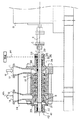
例えばボイラの給水に用いられる一軸多段ポンプの従来における代表的な構造は図6に示すようになっている(例えば特許文献1や特許文献2)。図に見られるように、一軸多段ポンプは、回転軸1、羽根車2、吸込口側端部用のラジアル軸受3、吐出口側端部用のラジアル軸受4、吐出口側端部用のスラスト軸受5、吸込口側端部用のシール装置6、吐出口側端部用のシール装置7、およびバランス装置8を備えている。また一軸多段ポンプはこれらの回転軸1や羽根車2などを収めるハウジング10を備えており、このハウジング10は、吸込口11が設けられた吸込ケーシング12、羽根車2を収めるステージ13、吐出口14が設けられた吐出ケーシング15、およびスタフィングボックス又はシールボックス16よりなっている。
For example, a conventional typical structure of a single-shaft multistage pump used for boiler water supply is as shown in FIG. 6 (for example, Patent Document 1 and Patent Document 2). As shown in the figure, the single-shaft multi-stage pump includes a rotary shaft 1, an
回転軸1は、駆動機Dの出力軸にスペーサSやカップリングCを介して直結で接続されおり、すべり軸受であるラジアル軸受3とラジアル軸受4にて吸込口側端部と吐出口側端部のそれぞれをラジアル方向に支持され、またスラスト軸受5にて吐出口側端部をスラスト方向に支持された状態で、駆動機Dからの回転駆動力を受けて回転する。ラジアル軸受3、4やスラスト軸受5は、一般的には油潤滑の軸受であり、油潤滑軸受の場合には図外の油圧系により潤滑油の供給を受けることになる。羽根車2は、回転軸1に複数段で配設されており、回転軸1の回転に伴って回転し、吸込口11から吸い込まれる供給水Wをその回転により各段で順じ加圧することにより所定圧まで加圧する。そして所定圧まで加圧された高圧水Whが吐出口から吐出される。
The rotary shaft 1 is directly connected to the output shaft of the driving machine D via a spacer S and a coupling C, and the suction port side end and the discharge port side end are connected by a radial bearing 3 and a
このような羽根車2による水の加圧過程において回転軸1にはその軸方向で吸込口側方向に向く推力(羽根車推力)を生じる。この羽根車推力を打ち消すために設けられているのがバランス装置8である。バランス装置8は、その部分を拡大した図7に示すように、ディスク型(図の例の型)はあるいはドラム型などで形成して回転軸1に固定装着されるバランス部材21、バランス部材21の吸込口側面に形成された中間室22、およびバランス部材21の吐出口側面に形成されたバランス室23により構成されている。そして中間室22はバランス部材21のボス部21bの外周に沿って形成されている微小な隙間(図示を省略)を介して吐出口14に連通しており高圧水Whにより高い圧力を生じている。一方、バランス室23は吸込口11にバランス管24を介して連通するとともに、羽根車推力の大きさに連動して間隙幅が変化する微小な隙間(図示を省略)を介して中間室22に連通し、中間室22の圧力よりも低い圧力(これは上記間隙幅の変化に応じて変化する)となっている。そしてこの中間室22とバランス室23との動的な圧力差によりバランス部材21をそのディスク部21dにおいて回転軸1の吐出口側方向へ押す状態となり、これにより羽根車推力に対抗する推力(バランス推力)が回転軸1に加わり、その結果、回転軸1に生じる推力を小さなものとし、あるいは回転軸1に実質的な推力を生じないようにすることができる。なお、このようなバランス装置8により回転軸1に実質的な推力が生じない場合にはスラスト軸受5は必ずしも必要でなく、これを省くようにする場合もある。
During the pressurizing process of water by the
シール装置6、7は、メカニカルシールで構成されている。具体的には、回転軸1に固定装着される回転環25とスタフィングボックス又はシールボックス16に固定状態で保持される固定環26との摺接によりシールをなす構造とされている。これらのシール装置6、7は、回転軸1を伝わって水が外へ漏れ出すのを防止する役目があり、同時に、油潤滑のラジアル軸受3、4に水が侵入するのを防止する役目も負っている。
The sealing devices 6 and 7 are constituted by mechanical seals. Specifically, a seal is formed by sliding contact between a
上記のような一軸多段ポンプについては以下に述べるような課題がある。その一つは、小型・省スペース化である。一軸多段ポンプは、1本の回転軸に羽根車が多段に設けられていることから、その軸方向にサイズが大きくなる。このため軸方向をできるだけ小型化してポンプ設置における省スペース化を図れるようにすることが求められている。これについて、例えば特許文献1や特許文献2に開示の一軸多段ポンプでは、軸受に水潤滑軸受を用いるようにしている。すなわち水潤滑軸受を用いることで、軸受に対する水のシール用として設けられているシール装置(図6におけるシール装置7)を不要とし、これにより軸方向についての小型化を実現して省スペース化を可能とし、さらに潤滑油供給のための油圧系が不要になることでポンプ周りが簡素化することでも省スペース化を可能としている。また特許文献1や特許文献2に開示の一軸多段ポンプでは、バランス装置とスラスト軸受を一体化させる構造としてバランス装置ないしスラスト軸受の一方を不要とすることでも軸方向についての小型化を実現して省スペース化を可能としている。
The above-described single-shaft multistage pump has the following problems. One of them is small size and space saving. Since the single-shaft multi-stage pump has the impellers provided in multiple stages on one rotating shaft, the size increases in the axial direction. For this reason, it is required to make the axial direction as small as possible so as to save space in installing the pump. In this regard, for example, in the single-shaft multistage pump disclosed in Patent Document 1 and
特許文献1や特許文献2に開示の技術のように軸受に水潤滑軸受を用いることは、一軸多段ポンプの小型・省スペース化に有効である。しかし、これらの従来技術では、軸受の水潤滑化を軸受用のシール装置の不要化という形で一軸多段ポンプの小型化に活かしているだけであり、未だ不十分なものがある。
The use of a water-lubricated bearing as the technique disclosed in Patent Document 1 or
また特許文献1で述べられているように、従来では水潤滑軸受として水潤滑カーボン軸受が用いられている。カーボン軸受は、カーボン材を焼結して形成されるものであり、固くて脆いために耐衝撃性に劣るという問題がある。この問題は一軸多段ポンプにおいては特に大きい。すなわち一軸多段ポンプでは1本の回転軸に羽根車が多段で設けられることから回転軸が長く、したがって軸受間のスパンが長くなる。このため回転軸の自重による撓み量が大きくなることや運転状態の変化による回転軸の半径方向の振れ回りで軸受に対して回転軸が片当たりになり易い。そして、起動時などのように軸受の摺動面に潤滑用の水の膜が十分に形成されていない状態で片当たりになると、耐衝撃性に劣るカーボン軸受では欠損する場合があるし、また水潤滑の潤滑材である水の粘性が油潤滑における油のそれに比べ低いために片当たりよる軸受の欠損の可能性も高くなり、信頼性に難があり、取扱いが難しくなる。さらにカーボン軸受には、摺動間隙(軸受の内面と回転軸の外面との間の隙間)に関する問題もある。すなわち潤滑材である水の粘性が低いために、十分な水膜を形成させるためには摺動間隙の精度が重要となるが、カーボン材の膨張係数は回転軸の膨張係数に比べて大きいため、ポンプ起動後の軸受温度の上昇により摺動間隙が拡がり過ぎて十分な水膜を形成できない場合も起こり得る。そのような場合には水膜切れによる固体潤滑となるため、軸受の磨耗を早めることになる。 As described in Patent Document 1, a water-lubricated carbon bearing is conventionally used as the water-lubricated bearing. A carbon bearing is formed by sintering a carbon material, and has a problem that it is inferior in impact resistance because it is hard and brittle. This problem is particularly serious in a single-shaft multistage pump. That is, in the single-shaft multi-stage pump, since the impeller is provided in multiple stages on one rotary shaft, the rotary shaft is long, and therefore the span between the bearings is long. For this reason, the amount of deflection due to the weight of the rotating shaft increases, and the rotating shaft tends to come into contact with the bearing due to the radial swing of the rotating shaft due to a change in the operating state. And if it comes into contact with a sliding film that does not have a sufficient film of water for lubrication, such as during startup, carbon bearings with poor impact resistance may be damaged, and Since the viscosity of water, which is a lubricant for water lubrication, is lower than that of oil in oil lubrication, there is a high possibility of bearing failure due to contact with each other, and reliability is difficult and handling becomes difficult. Further, the carbon bearings also have a problem with respect to the sliding gap (the gap between the inner surface of the bearing and the outer surface of the rotating shaft). In other words, since the viscosity of water as a lubricant is low, the accuracy of the sliding gap is important to form a sufficient water film, but the expansion coefficient of the carbon material is larger than the expansion coefficient of the rotating shaft. Further, there may be a case where a sufficient water film cannot be formed because the sliding gap is excessively widened due to an increase in bearing temperature after the pump is started. In such a case, solid lubrication is caused by a water film breakage, so that wear of the bearing is accelerated.
他の課題はシール装置に関連したメンテナンス性の課題である。シール装置には上記のようにメカニカルシールを用いるのが通常であるが、このメカニカルシールは一軸多段ポンプの各種構成部品のなかで最も消耗の早い部品であり、それだけ保守点検の頻度も高くなる。シール装置の保守点検の場合、摺動面の磨耗状態を検査するなどのためにシール装置の回転環と固定環を取り外す必要がある。これら回転環と固定環がそれぞれ一体の筒形になっている従来のシール装置において回転環と固定環の取外作業をなすには、例えば吸込口側端部用のシール装置の場合、まず駆動機と回転軸との接続に用いられているスペーサやカップリングを取り外して回転軸の端部を開放した状態にし、それから回転環と固定環を回転軸に沿って抜き取って取り外すという作業手順を必要とした。また、シール装置の点検のために、点検が不要である軸受まで分解する必要もあった。このため保守点検に多大な時間を要することになっており、メンテナンス性について改善が求められていた。 Another problem is a maintenance problem related to the sealing device. Normally, a mechanical seal is used for the sealing device as described above. However, this mechanical seal is the fastest consumable component among the various components of the single-shaft multi-stage pump, and the frequency of maintenance and inspection is increased accordingly. In the maintenance and inspection of the sealing device, it is necessary to remove the rotating ring and the stationary ring of the sealing device in order to inspect the wear state of the sliding surface. To remove the rotating ring and the fixed ring in the conventional sealing device in which the rotating ring and the fixed ring are each formed into an integral cylindrical shape, for example, in the case of a sealing device for the inlet side end, first drive It is necessary to remove the spacer and coupling used to connect the machine to the rotating shaft, open the rotating shaft end, and then remove and remove the rotating ring and stationary ring along the rotating shaft. It was. Further, in order to inspect the sealing device, it was necessary to disassemble even the bearing that does not require inspection. For this reason, a great deal of time is required for maintenance and inspection, and improvement is required for maintainability.
本発明は、従来の一軸多段ポンプにおける以上のような事情を背景になされたものであり、より一層の小型・省スペース化を可能とする一軸多段ポンプの提供を第1の目的とし、また水潤滑における軸受に対する信頼性の高い一軸多段ポンプの提供を第2の目的とし、さらにメンテナンス性に優れる一軸多段ポンプの提供を第3の目的としている。 The present invention has been made in the background of the above situation in the conventional single-shaft multi-stage pump. The first object of the present invention is to provide a single-shaft multi-stage pump that enables further miniaturization and space saving. A second object is to provide a highly reliable single-shaft multi-stage pump for bearings in lubrication, and a third object is to provide a single-shaft multi-stage pump with excellent maintainability.
本発明では上記目的のために、吸入した水を加圧するための羽根車が多段に配設された回転軸と、この回転軸を支持するラジアル軸受と、前記回転軸を駆動するための駆動機と、前記回転軸の一端側と前記駆動機とを接続するためのカップリングと、前記カップリング側であって補助ケーシング内に収容された前記ラジアル軸受とともに前記補助ケーシング内に収容され、かつ前記ラジアル軸受と回転軸を伝わって前記水が漏れるのを防止する回転環と固定環からなるシール装置と、を備えている一軸多段ポンプにおいて、前記ラジアル軸受として、摺動要素が樹脂材料で形成され、潤滑に水を用いることができるようにされた水潤滑樹脂軸受を用い、前記シール装置の回転環と固定環は、二つの半円筒部材を組合わせた二つ割構造として、それぞれが径方向に分割できるように構成され、かつ前記カップリングを取り外すことなく前記補助ケーシングの前記カップリング側端部に着脱可能に設けられた後部カバーを外して、前記補助ケーシング内より前記シール装置を取り出すことにより、前記シール装置のメンテナンスを可能としたことを特徴としている。
In the present invention, for the above purpose, a rotating shaft in which impellers for pressurizing sucked water are arranged in multiple stages, a radial bearing that supports the rotating shaft, and a driving machine for driving the rotating shaft are provided. And a coupling for connecting one end side of the rotating shaft and the driving machine, the radial bearing housed in the auxiliary casing on the coupling side, and housed in the auxiliary casing, and In a single-shaft multistage pump comprising a radial bearing and a sealing device comprising a rotating ring and a stationary ring that prevents the water from leaking along the rotating shaft, the sliding element is formed of a resin material as the radial bearing. , using water lubricated resin bearing is to be able to use water in the lubricant, the fixed ring and the rotating ring of the seal device, as two split structure which combined two semi-cylindrical member, Respectively is configured to be divided in the radial direction, and remove the said coupling end detachably provided with a rear cover of the auxiliary casing without removing the coupling from said auxiliary casing The maintenance of the sealing device can be performed by taking out the sealing device .
本発明では上記目的のために、前記水潤滑の軸受は、摺動要素が樹脂材料で形成された水潤滑樹脂軸受が用いられていることを特徴としている。
また前記樹脂材料は、ポリエーテルエーテルケトン(PEEK)であることを特徴としている。
In the present invention, for the above purpose, the water-lubricated bearing is characterized in that a water-lubricated resin bearing in which a sliding element is formed of a resin material is used.
The resin material is polyetheretherketone (PEEK).
本発明では上記目的のために、前記羽根車の加圧作用に起因して生じる軸方向の推力に対抗するバランス推力を前記回転軸に加えるバランス装置を備え、前記水潤滑樹脂軸受を、前記バランス装置におけるバランス部材の外径側に配置して、このバランス部材を介して前記水潤滑樹脂軸受により回転軸を支承するようにしたことを特徴としている。In the present invention, for the above-mentioned purpose, a balance device for applying a balance thrust against the axial thrust generated due to the pressurizing action of the impeller to the rotating shaft is provided, and the water-lubricating resin bearing is provided with the balance. It arrange | positions at the outer diameter side of the balance member in an apparatus, and the rotating shaft was supported by the said water lubrication resin bearing through this balance member, It is characterized by the above-mentioned.
本発明では、ラジアル軸受に水潤滑の軸受を用い、この水潤滑ラジアル軸受によりバランス装置のバランス部材を介して回転軸の支持をなすようにしている。このため、上記のような水潤滑軸受がもたらす軸受用シール装置の不要化による軸方向についての小型化などに加えて、ラジアル軸受の一つとバランス装置を一体化させることによる軸方向についての小型化を図れ、さらに一層の小型・省スペース化を実現できる。In the present invention, a water-lubricated bearing is used as the radial bearing, and the rotary shaft is supported by the water-lubricated radial bearing via the balance member of the balance device. For this reason, in addition to the downsizing in the axial direction by eliminating the need for the bearing seal device provided by the water-lubricated bearing as described above, the downsizing in the axial direction by integrating one of the radial bearings and the balance device. To achieve further reductions in size and space.
本発明では、ラジアル軸受に水潤滑の軸受を用い、この水潤滑ラジアル軸受によりバランス装置のバランス部材を介して回転軸の支持をなすようにしている。このため、上記のような水潤滑軸受がもたらす軸受用シール装置の不要化による軸方向についての小型化などに加えて、ラジアル軸受の一つとバランス装置を一体化させることによる軸方向についての小型化を図れ、さらに一層の小型・省スペース化を実現できる。In the present invention, a water-lubricated bearing is used as the radial bearing, and the rotary shaft is supported by the water-lubricated radial bearing via the balance member of the balance device. For this reason, in addition to the downsizing in the axial direction by eliminating the need for the bearing seal device provided by the water-lubricated bearing as described above, the downsizing in the axial direction by integrating one of the radial bearings and the balance device. To achieve further reductions in size and space.
また本発明では、軸受に水潤滑樹脂軸受を用いるようにしている。その樹脂軸受は、一軸多段ポンプ用の水潤滑軸受として適した特性を多く有しており、水潤滑における軸受に対する信頼性を大幅に高めることができるようになる。In the present invention, a water-lubricated resin bearing is used as the bearing. The resin bearing has many characteristics suitable as a water-lubricated bearing for a single-shaft multi-stage pump, and can greatly increase the reliability of the bearing in water lubrication.
さらに本発明では、複数に分割された分割円筒部材を組み合わせてなる分割構造でシール装置の回転環と固定環を形成するようにしている。このため、駆動機と回転軸との接続に用いられているスペーサやカップリングを取り外さなくともシール装置の保守点検作業を行えるようになり、シール装置のメンテナンス性を大幅に向上させることができる。 Furthermore, in the present invention, the rotating ring and the stationary ring of the sealing device are formed with a divided structure formed by combining a plurality of divided cylindrical members. For this reason, it becomes possible to perform maintenance and inspection work of the sealing device without removing the spacers and couplings used for connecting the drive unit and the rotating shaft, and the maintenance performance of the sealing device can be greatly improved.
以下、本発明を実施する際の好ましい形態について説明する。図1に第1の実施形態による一軸多段ポンプの構成を示す。本実施形態における一軸多段ポンプは、上で説明した図6における従来の一軸多段ポンプと共通する部分を有している。それら共通する部分には同一の符号を付し、それについての説明は上での説明を援用することで適宜省略する。 Hereinafter, preferred modes for carrying out the present invention will be described. FIG. 1 shows the configuration of a single-shaft multistage pump according to the first embodiment. The single-shaft multistage pump in the present embodiment has a common part with the conventional single-shaft multistage pump in FIG. 6 described above. The common parts are denoted by the same reference numerals, and the description thereof is appropriately omitted by using the above description.
本実施形態の一軸多段ポンプで特徴的な構成は、吸込口側端部用のラジアル軸受31と吐出口側端部用のラジアル軸受32に水潤滑軸受を用いていること、吸込口側端部用のラジアル軸受31を水潤滑軸受としたことに関連して、吸込口側端部用のシール装置33をラジアル軸受31とともに共通の吸込口側端部用補助ケーシング34の内部に納めるようにしていること、およびシール装置33における回転環35と回転環36をそれぞれ分割構造としていることである。
The characteristic configuration of the single-shaft multistage pump of the present embodiment is that a water-lubricated bearing is used for the
ラジアル軸受31やラジアル軸受32における水潤滑軸受には、樹脂材料(合成樹脂材料)で形成した樹脂軸受を用いる。樹脂軸受は、耐衝撃性と摺動特性に優れている。このため、回転軸が長くて大きな撓みや振れ回りを生じ易い一軸多段ポンプにあっても、その大きな撓みや振れ回りによる片当たりで軸受に欠損を生じるようなことがない。また樹脂軸受は、変形追従性に優れていることから一軸多段ポンプにおける長い回転軸の撓みなどにも容易に追従することができ、軸受に対する回転軸の片当たりの発生も少なくすることができる。また樹脂軸受は、その膨張係数が回転軸の膨張係数に比べて小さいためにポンプ起動後の軸受温度の上昇で摺動間隙を狭くする状態になる。したがって粘性の低い水による潤滑の場合でも十分な水膜を形成させ易く、水膜切れによる固体潤滑となるような状態を招く可能性が少なくなり、軸受の寿命を長くすることができる。さらに樹脂軸受は、高い耐熱性を有していて摂氏300度以上の高温にも耐えることができ、例えばボイラへの給水のように高温の水をポンプアップする場合でも軸受への冷却水の供給を不要とすることができる。
A resin bearing formed of a resin material (synthetic resin material) is used as the water-lubricated bearing in the
樹脂軸受の樹脂材料には、例えばPA(ポリアミド)、POM(ポリアセタール)、PBT(ポリブチレンテレフタレート)、PET(ポリエチレンテレフタレート)、PPE(ポリフェニルン・エーテル)、PC(ポリカーボネート)、UHMW-PE(超高分子ポリエチレン)、PTFE(ポリ四フッ化エチレン)、PPS(ポリフェニレンサルファイド)、PI(ポリイミド)、PEEK(ポリエーテルエーテルケトン)、PAR(ポリアリレート)、PSF(ポリサルフォン)、PEI(ポリエーテルイミド)、PAI(ポリアミドイミド)、PES(ポリエーテルスルホン)などの各樹脂やメタセシス重合可能なシクロオレフィン類をメタセシス重合触媒の存在下に重合させて得られる樹脂(仮に、メタセシス重合シクロオレフィン系樹脂と呼ぶ)のうち少なくとも一種類を含むものを好ましいものとして用いることができる。より好ましくは、これらの樹脂を炭素繊維で強化した材料を用いる。炭素繊維強化樹脂材料としては、炭素繊維強化PEEK、炭素繊維強化PPS、および炭素繊維強化メタセシス重合シクロオレフィン系樹脂を特に好ましいものとして用いることができる。 Examples of resin materials for resin bearings include PA (polyamide), POM (polyacetal), PBT (polybutylene terephthalate), PET (polyethylene terephthalate), PPE (polyphenylone ether), PC (polycarbonate), UHMW-PE (ultra-high) Molecular polyethylene), PTFE (polytetrafluoroethylene), PPS (polyphenylene sulfide), PI (polyimide), PEEK (polyetheretherketone), PAR (polyarylate), PSF (polysulfone), PEI (polyetherimide), Resins obtained by polymerizing each resin such as PAI (polyamideimide) and PES (polyethersulfone) and cycloolefins capable of metathesis polymerization in the presence of a metathesis polymerization catalyst (tentatively called metathesis polymerization cycloolefin resin) Of these, those containing at least one type can be used as preferred. wear. More preferably, a material obtained by reinforcing these resins with carbon fibers is used. As the carbon fiber reinforced resin material, carbon fiber reinforced PEEK, carbon fiber reinforced PPS, and carbon fiber reinforced metathesis-polymerized cycloolefin resin can be used as particularly preferable ones.
ラジアル軸受31やラジアル軸受32に水潤滑樹脂軸受を用いるようにしたことにより、まず一つとして、水潤滑であることにより、上述のように軸受への水の侵入を防ぐためのシール装置(図6におけるシール装置7)が不要となることで、軸方向についての小型化が図られ省スペース化が可能となり、また潤滑油供給のための油圧系が不要になることでポンプ周りが簡素化することでも省スペース化が可能となる。それからこのことに加えて、上記のように樹脂軸受が一軸多段ポンプ用の水潤滑軸受として適した特性を多く有していることにより、水潤滑における軸受に対する信頼性を大幅に高めることができるようになる。
By using water-lubricating resin bearings for the
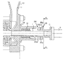
補助ケーシング34は、上記のように、ラジアル軸受31とシール装置33を共通に収めるためのものであり、その周辺を部分的に拡大した図2に示すように、ラジアル軸受31を支持するための支持部37とシール装置33における固定環36の保持に機能する固定環保持部36sを内周面に形成した円筒状に形成されている。また補助ケーシング34は、その前端にフランジ部38が形成され、その後端を、回転軸1の貫通をなせるようにした着脱可能な後部カバー39(図2ではその図示を省略してある)にて覆い、後述のようにしてシール装置33における回転環35と固定環36を取り外す際にそこを開放できるようにされており、そのフランジ部38を介して図示せぬボルトで吸込ケーシング12に取り付けられている。
The
この補助ケーシング34に収められたラジアル軸受31には潤滑水を供給する必要があり、またシール装置33にも摺動面の洗浄などのために水を供給する必要があり、それらのための注水Wfがなされる場合がある。注水Wfが必要な場合には、吸込口11や吐出口14から分岐した水や別途設けた注水系から供給される水が用いられる。注水Wfによる水は、シール装置33の摺動面の洗浄などとラジアル軸受31の潤滑に働いた後、吸込口11に流入し、あるいは外部に排出される。ここで、ラジアル軸受31の潤滑水に吐出口14からの高圧水を用いるようにする場合には、ラジアル軸受31を静圧軸受とすることができる。このことはラジアル軸受32についても同様である。
Lubricating water needs to be supplied to the
このように補助ケーシング34にラジアル軸受31とシール装置33を共通に収めるようにしたのは、ラジアル軸受31を水潤滑軸受としたことから、ラジアル軸受31への水の侵入を防止する必要がなくなったからである。この結果、従来ではシール装置用として別に設けられていた図6におけるスタフィングボックス又はシールボックス16を不要とすることができ、それだけ一軸多段ポンプを軸方向について小型化することが可能となる。
The reason why the
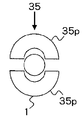
シール装置33における回転環35は、図3に示すように、対称に形成した二つの半円筒部材35p、35pを組み合わせる二つ割り構造の円筒形に形成され、固定環36についても同様に、対称に形成した二つの半円筒部材36p、36pを組み合わせる二つ割り構造の円筒形に形成されている。このようにシール装置33の回転環35と固定環36を、複数に分割した分割円筒部材の組み合わせによる分割構造(本例では二つ割り構造)としたことにより、シール装置のメンテナンス性が大幅に向上する。シール装置の保守点検では回転環35と固定環36を回転軸1に沿って取り外す必要がある。この回転環35と固定環36の取外し作業は、本発明における構造であると、駆動機Dと回転軸1との接続に用いられているスペーサSやカップリングCを取り外さなくとも行うことができる。すなわち図2に示すように、スペーサSやカップリングCを介して回転軸1が駆動機に接続したままの状態で、まず補助ケーシング34の後部カバー39を外してその後端を開放し、それから回転環35と固定環36を補助ケーシング34から引き出せば、二つ割り構造であることから回転環35を回転軸1から容易に取り外すことができる。このように、回転軸1が駆動機と接続したままの状態で回転環35と固定環36を回転軸1から取り外すことを可能としたことにより、スペーサSやカップリングCの取外し作業を必要としていた従来の場合に比べ、大幅にメンテナンス性が向上することになる。
As shown in FIG. 3, the
なお、本実施形態では、ラジアル軸受32についても、これを収めるために回転軸1の吐出口側端部に吐出口側端部用補助ケーシング41を設け、この補助ケーシング41を後部カバー42で覆うことにより回転軸1の吐出口側端部を密閉するようにしている。このように回転軸1の吐出口側端部を密閉状態とすることにより、ラジアル軸受32が水潤滑軸受であることと関連して、シール装置を不要にすることができ、上記のような軸方向についての小型化を図れる。ただ、何らかの理由から回転軸1の吐出口側端部を開放にする必要のある場合もある。そのような場合には吐出口側端部についてもシール装置を設けることになるが、そのシール装置もシール装置33と同様の構造とするのが好ましい。
In the present embodiment, the
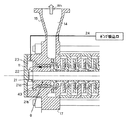
図4に第2の実施形態による一軸多段ポンプの構成を示す。本実施形態における一軸多段ポンプは、基本的には第1の実施形態における一軸多段ポンプと同様である。したがって第1の実施形態における一軸多段ポンプと共通する部分には同一の符号を付し、それについての説明は上での説明を援用することで適宜省略する。 FIG. 4 shows the configuration of a single-shaft multistage pump according to the second embodiment. The single-shaft multistage pump in the present embodiment is basically the same as the single-shaft multistage pump in the first embodiment. Therefore, the same code | symbol is attached | subjected to the part which is common in the single axis | shaft multistage pump in 1st Embodiment, The description about it is abbreviate | omitted suitably by using the description above.
本実施形態の一軸多段ポンプで特徴的な構成は、吐出口側端部用の水潤滑ラジアル軸受43による回転軸1の支持をバランス装置8のバランス部材21を介してなすようにしていることである。具体的には、図5に部分的に拡大して示すように、回転軸1に固着されたバランス部材21のボス部21bをラジアル軸受43で支持し、これによりラジアル軸受43による回転軸1の支持をなすようにしている。
The characteristic configuration of the single-shaft multi-stage pump of this embodiment is that the rotary shaft 1 is supported by the water-lubricated
このようにしたことによりラジアル軸受43をバランス装置8に一体化させることができる。この結果、例えば第1の実施形態における一軸多段ポンプとの比較でいえば、ラジアル軸受32あるいはバランス装置8が占めていたスペースを不要とすることができ、さらに一層、軸方向についての小型化を図れることになる。なお、本実施形態でも回転軸1の吐出口側端部を後部カバー42にて覆うことにより回転軸1の吐出口側端部を密閉するようにすることで、この端部におけるシール装置の不要化を図っている。
By doing so, the
以上説明したように本発明によれば、一軸多段ポンプについて、その軸方向のより一層の小型・省スペース化を実現でき、また水潤滑における軸受に対する信頼性を大幅に高めることができ、さらにシール装置のメンテナンス性を大幅に向上させることができる。このような本発明は、一軸多段ポンプのさらなる高機能化に大きく寄与することができる。 As described above, according to the present invention, the single-shaft multi-stage pump can be further reduced in size and space in the axial direction, can greatly improve the reliability of the bearing in water lubrication, and can be further sealed. The maintainability of the apparatus can be greatly improved. Such an invention can greatly contribute to further enhancement of the function of the single-shaft multi-stage pump.
1 回転軸
2 羽根車
8 バランス装置
21 バランス部材
31、32、43 ラジアル軸受
35 回転環
36 固定環
35p 半円筒部材
36p 半円筒部材
DESCRIPTION OF SYMBOLS 1
Claims (3)
前記ラジアル軸受として、摺動要素が樹脂材料で形成され、潤滑に水を用いることができるようにされた水潤滑樹脂軸受を用い、
前記シール装置の回転環と固定環は、二つの半円筒部材を組合わせた二つ割構造として、それぞれが径方向に分割できるように構成され、かつ前記カップリングを取り外すことなく前記補助ケーシングの前記カップリング側端部に着脱可能に設けられた後部カバーを外して、前記補助ケーシング内より前記シール装置を取り出すことにより、前記シール装置のメンテナンスを可能としたことを特徴とする一軸多段ポンプ。 A rotating shaft in which impellers for pressurizing sucked water are arranged in multiple stages, a radial bearing that supports the rotating shaft, a drive unit for driving the rotating shaft, and one end of the rotating shaft; A coupling for connecting the drive unit, and the radial bearing housed in the auxiliary casing on the coupling side and housed in the auxiliary casing, and transmitted through the radial bearing and the rotary shaft, In a single-shaft multi-stage pump comprising a rotary device that prevents water from leaking and a sealing device that includes a stationary ring,
Examples radial bearing, the sliding element is made of a resin material, using water lubricated resin bearing is to be able to use water to lubrication,
The rotating ring and the stationary ring of the sealing device are configured as a split structure in which two semi-cylindrical members are combined so that each can be divided in the radial direction, and the auxiliary casing of the auxiliary casing can be removed without removing the coupling . Remove the rear cover provided detachably on the coupling-side end, by removing the sealing device from said auxiliary casing, single-shaft multistage pump, characterized in that to allow maintenance of the sealing device.
Priority Applications (6)
| Application Number | Priority Date | Filing Date | Title |
|---|---|---|---|
| JP2004007907A JP4352903B2 (en) | 2004-01-15 | 2004-01-15 | Single-shaft multistage pump |
| US10/912,554 US7198457B2 (en) | 2004-01-15 | 2004-08-06 | Single-shaft multistage pump |
| KR1020040062385A KR100614950B1 (en) | 2004-01-15 | 2004-08-09 | Single-shaft multistage pump |
| EP04018955A EP1555439B1 (en) | 2004-01-15 | 2004-08-10 | Single-shaft multistage pump |
| DE602004023581T DE602004023581D1 (en) | 2004-01-15 | 2004-08-10 | Multi-stage single shaft pump |
| CNB200410068300XA CN100523516C (en) | 2004-01-15 | 2004-08-27 | Single-shaft multistage pump |
Applications Claiming Priority (1)
| Application Number | Priority Date | Filing Date | Title |
|---|---|---|---|
| JP2004007907A JP4352903B2 (en) | 2004-01-15 | 2004-01-15 | Single-shaft multistage pump |
Publications (3)
| Publication Number | Publication Date |
|---|---|
| JP2005201137A JP2005201137A (en) | 2005-07-28 |
| JP2005201137A5 JP2005201137A5 (en) | 2008-03-21 |
| JP4352903B2 true JP4352903B2 (en) | 2009-10-28 |
Family
ID=34616885
Family Applications (1)
| Application Number | Title | Priority Date | Filing Date |
|---|---|---|---|
| JP2004007907A Expired - Fee Related JP4352903B2 (en) | 2004-01-15 | 2004-01-15 | Single-shaft multistage pump |
Country Status (6)
| Country | Link |
|---|---|
| US (1) | US7198457B2 (en) |
| EP (1) | EP1555439B1 (en) |
| JP (1) | JP4352903B2 (en) |
| KR (1) | KR100614950B1 (en) |
| CN (1) | CN100523516C (en) |
| DE (1) | DE602004023581D1 (en) |
Families Citing this family (11)
| Publication number | Priority date | Publication date | Assignee | Title |
|---|---|---|---|---|
| US20090028696A1 (en) * | 2007-07-26 | 2009-01-29 | Gannett Thomas P | Thermoplastic polymer bushings |
| WO2009158695A1 (en) * | 2008-06-27 | 2009-12-30 | Greene, Tweed Of Delaware, Inc. | Split bearing assemblies, air-cooled heat exchangers and related methods |
| CA2736952C (en) | 2008-09-10 | 2016-11-29 | Pentair Pump Group, Inc. | High-efficiency, multi-stage centrifugal pump and method of assembly |
| JP6420701B2 (en) * | 2015-03-24 | 2018-11-07 | 株式会社荏原製作所 | pump |
| CN105443399B (en) * | 2016-01-07 | 2018-11-06 | 上海电气凯士比核电泵阀有限公司 | A kind of certainly cooling electronic auxiliary feed water pump |
| CN106640745A (en) * | 2016-12-14 | 2017-05-10 | 衡阳市力源动力制造有限公司 | Multistage vane wheel high-lift sewage electric pump |
| KR101998620B1 (en) * | 2018-06-29 | 2019-07-10 | 김성환 | Dry suction device having external separator |
| KR102209759B1 (en) * | 2018-09-12 | 2021-02-03 | 주식회사에스에이치이 | Heat pump for deep frying oil |
| EP3857072B1 (en) * | 2018-09-27 | 2024-01-03 | KSB SE & Co. KGaA | A multistage pump with axial thrust optimization |
| US11655822B1 (en) * | 2022-08-03 | 2023-05-23 | Flowserve Pte. Ltd. | Multi-stage pump or turbine for controlling fluids with significant variations in gas fraction |
| KR102617553B1 (en) | 2023-08-28 | 2023-12-22 | (주)그린텍 | Balance device of multistage pump |
Family Cites Families (12)
| Publication number | Priority date | Publication date | Assignee | Title |
|---|---|---|---|---|
| US3025070A (en) * | 1959-12-11 | 1962-03-13 | John C Copes | Split mechanical seals |
| FI940630A (en) | 1994-02-11 | 1995-08-12 | Ahlstroem Oy | centrifugal |
| JP2843280B2 (en) * | 1995-09-29 | 1999-01-06 | アイシン精機株式会社 | Water pump |
| JP3611442B2 (en) | 1998-03-25 | 2005-01-19 | 株式会社荏原製作所 | Double barrel multistage pump structure |
| JP2001124070A (en) | 1999-10-21 | 2001-05-08 | Hitachi Ltd | Water lubricated bearing device |
| JP2001248586A (en) | 2000-03-07 | 2001-09-14 | Mitsubishi Heavy Ind Ltd | Centrifugal pump |
| US6485023B2 (en) * | 2000-05-04 | 2002-11-26 | Flowserve Management Company | Split mechanical face seal |
| DE10038586A1 (en) | 2000-08-03 | 2002-02-14 | Ksb Ag | Axial thrust |
| JP3961212B2 (en) * | 2000-11-01 | 2007-08-22 | Ntn株式会社 | Sliding bearing for water pump |
| DE10058499A1 (en) * | 2000-11-24 | 2002-05-29 | Ksb Ag | Plain bearings for a centrifugal pump |
| JP2002242881A (en) | 2001-02-19 | 2002-08-28 | Mitsubishi Heavy Ind Ltd | Bearing structure for water supplying pump of high- speed, multi-stage boiler |
| JP2006009819A (en) * | 2004-06-22 | 2006-01-12 | Ntn Corp | Sliding bearing for cooling water circulation pump of fuel cell |
-
2004
- 2004-01-15 JP JP2004007907A patent/JP4352903B2/en not_active Expired - Fee Related
- 2004-08-06 US US10/912,554 patent/US7198457B2/en not_active Expired - Fee Related
- 2004-08-09 KR KR1020040062385A patent/KR100614950B1/en not_active IP Right Cessation
- 2004-08-10 EP EP04018955A patent/EP1555439B1/en not_active Expired - Fee Related
- 2004-08-10 DE DE602004023581T patent/DE602004023581D1/en active Active
- 2004-08-27 CN CNB200410068300XA patent/CN100523516C/en not_active Expired - Fee Related
Also Published As
| Publication number | Publication date |
|---|---|
| CN100523516C (en) | 2009-08-05 |
| KR100614950B1 (en) | 2006-08-25 |
| DE602004023581D1 (en) | 2009-11-26 |
| US7198457B2 (en) | 2007-04-03 |
| JP2005201137A (en) | 2005-07-28 |
| CN1641224A (en) | 2005-07-20 |
| EP1555439A3 (en) | 2006-03-15 |
| KR20050075271A (en) | 2005-07-20 |
| EP1555439B1 (en) | 2009-10-14 |
| US20050158165A1 (en) | 2005-07-21 |
| EP1555439A2 (en) | 2005-07-20 |
Similar Documents
| Publication | Publication Date | Title |
|---|---|---|
| JP4352903B2 (en) | Single-shaft multistage pump | |
| US8016571B2 (en) | Thrust and intake chamber for pump | |
| JP5291363B2 (en) | pump | |
| GB2290113A (en) | Centrifugal pump shaft seal cooling and venting | |
| JP4078833B2 (en) | Double suction centrifugal pump | |
| US20200355219A1 (en) | Tilting pad journal bearing and rotary machine using same | |
| RU2643269C2 (en) | Compressor rotor seal | |
| US20210088056A1 (en) | Pump for conveying a fluid | |
| US20030035721A1 (en) | Liner for centrifugal slurry pumps | |
| EP3366956B1 (en) | Sealing device and rotating machine | |
| AU2016269666B2 (en) | Combined bearing and turbomachine including said bearing | |
| CN113286947B (en) | Pump with bearing lubrication system | |
| JP5512168B2 (en) | Thrust bearing seal for turbocharger | |
| CN108626162B (en) | Oil seal structure and compression apparatus including the same | |
| JP2003322098A (en) | Uniaxial multistage pump | |
| WO2011038347A1 (en) | Axial fan compact bearing viscous pump | |
| JP2006183465A (en) | Centrifugal compressor | |
| US11933321B2 (en) | Rotary pump for conveying a fluid | |
| WO2017022517A1 (en) | Bearing device and rotary machine | |
| RU2597719C2 (en) | Device for transfer of fluid medium | |
| JP7243848B2 (en) | Multi-lobe bearing and supercharger | |
| JP2005201054A (en) | Pump | |
| JP4646104B2 (en) | Double suction type horizontal shaft pump with non-water-filled shaft seal device | |
| JP2004108170A (en) | Centrifugal compressor | |
| JP2001041193A (en) | Pump with self-liquid fluid bearing |
Legal Events
| Date | Code | Title | Description |
|---|---|---|---|
| A521 | Request for written amendment filed |
Free format text: JAPANESE INTERMEDIATE CODE: A523 Effective date: 20050928 |
|
| A621 | Written request for application examination |
Free format text: JAPANESE INTERMEDIATE CODE: A621 Effective date: 20050928 |
|
| A711 | Notification of change in applicant |
Free format text: JAPANESE INTERMEDIATE CODE: A712 Effective date: 20060920 |
|
| RD02 | Notification of acceptance of power of attorney |
Free format text: JAPANESE INTERMEDIATE CODE: A7422 Effective date: 20060921 |
|
| A521 | Request for written amendment filed |
Free format text: JAPANESE INTERMEDIATE CODE: A523 Effective date: 20080131 |
|
| A977 | Report on retrieval |
Free format text: JAPANESE INTERMEDIATE CODE: A971007 Effective date: 20081104 |
|
| A131 | Notification of reasons for refusal |
Free format text: JAPANESE INTERMEDIATE CODE: A131 Effective date: 20081111 |
|
| A521 | Request for written amendment filed |
Free format text: JAPANESE INTERMEDIATE CODE: A523 Effective date: 20090109 |
|
| A02 | Decision of refusal |
Free format text: JAPANESE INTERMEDIATE CODE: A02 Effective date: 20090217 |
|
| A521 | Request for written amendment filed |
Free format text: JAPANESE INTERMEDIATE CODE: A523 Effective date: 20090417 |
|
| A911 | Transfer to examiner for re-examination before appeal (zenchi) |
Free format text: JAPANESE INTERMEDIATE CODE: A911 Effective date: 20090422 |
|
| A131 | Notification of reasons for refusal |
Free format text: JAPANESE INTERMEDIATE CODE: A131 Effective date: 20090526 |
|
| A521 | Request for written amendment filed |
Free format text: JAPANESE INTERMEDIATE CODE: A523 Effective date: 20090608 |
|
| TRDD | Decision of grant or rejection written | ||
| A01 | Written decision to grant a patent or to grant a registration (utility model) |
Free format text: JAPANESE INTERMEDIATE CODE: A01 Effective date: 20090707 |
|
| A01 | Written decision to grant a patent or to grant a registration (utility model) |
Free format text: JAPANESE INTERMEDIATE CODE: A01 |
|
| A61 | First payment of annual fees (during grant procedure) |
Free format text: JAPANESE INTERMEDIATE CODE: A61 Effective date: 20090720 |
|
| R150 | Certificate of patent or registration of utility model |
Free format text: JAPANESE INTERMEDIATE CODE: R150 |
|
| FPAY | Renewal fee payment (event date is renewal date of database) |
Free format text: PAYMENT UNTIL: 20120807 Year of fee payment: 3 |
|
| FPAY | Renewal fee payment (event date is renewal date of database) |
Free format text: PAYMENT UNTIL: 20120807 Year of fee payment: 3 |
|
| FPAY | Renewal fee payment (event date is renewal date of database) |
Free format text: PAYMENT UNTIL: 20130807 Year of fee payment: 4 |
|
| S111 | Request for change of ownership or part of ownership |
Free format text: JAPANESE INTERMEDIATE CODE: R313111 |
|
| R350 | Written notification of registration of transfer |
Free format text: JAPANESE INTERMEDIATE CODE: R350 |
|
| LAPS | Cancellation because of no payment of annual fees |