JP4352829B2 - Intake device for V-type internal combustion engine - Google Patents
Intake device for V-type internal combustion engine Download PDFInfo
- Publication number
- JP4352829B2 JP4352829B2 JP2003327059A JP2003327059A JP4352829B2 JP 4352829 B2 JP4352829 B2 JP 4352829B2 JP 2003327059 A JP2003327059 A JP 2003327059A JP 2003327059 A JP2003327059 A JP 2003327059A JP 4352829 B2 JP4352829 B2 JP 4352829B2
- Authority
- JP
- Japan
- Prior art keywords
- intake
- collector
- internal combustion
- combustion engine
- volume chamber
- Prior art date
- Legal status (The legal status is an assumption and is not a legal conclusion. Google has not performed a legal analysis and makes no representation as to the accuracy of the status listed.)
- Expired - Fee Related
Links
Images


Classifications
-
- Y—GENERAL TAGGING OF NEW TECHNOLOGICAL DEVELOPMENTS; GENERAL TAGGING OF CROSS-SECTIONAL TECHNOLOGIES SPANNING OVER SEVERAL SECTIONS OF THE IPC; TECHNICAL SUBJECTS COVERED BY FORMER USPC CROSS-REFERENCE ART COLLECTIONS [XRACs] AND DIGESTS
- Y02—TECHNOLOGIES OR APPLICATIONS FOR MITIGATION OR ADAPTATION AGAINST CLIMATE CHANGE
- Y02T—CLIMATE CHANGE MITIGATION TECHNOLOGIES RELATED TO TRANSPORTATION
- Y02T10/00—Road transport of goods or passengers
- Y02T10/10—Internal combustion engine [ICE] based vehicles
- Y02T10/12—Improving ICE efficiencies
Landscapes
- Characterised By The Charging Evacuation (AREA)
Description
この発明は、V型内燃機関の吸気装置、特に、機関運転条件に応じて吸気系を各バンク毎に独立した状態と両バンクで一体となった状態に切り換えることができる可変機構を備えた吸気装置の改良に関する。 The present invention relates to an intake system for a V-type internal combustion engine, and more particularly, an intake system having a variable mechanism that can switch an intake system between an independent state for each bank and an integrated state in both banks according to engine operating conditions. It relates to the improvement of the device.
例えばV型6気筒内燃機関においては、一方のバンクの#1,#3,#5気筒と、他方のバンクの#2,#4,#6気筒とで、吸気行程が重ならないことから、両バンクの吸気系を分離することにより低中速領域で大きな吸気動的効果を得ることができる。そして、高速高負荷域では、実質的な吸気管長を短くするように、左右バンクの容積室を互いに連通させることで、充填効率が向上することが知られている。
For example, in a V-type 6-cylinder internal combustion engine, the intake strokes of
そのため、各バンク毎に一対の容積室を設け、かつ両容積室を連通する連絡通路に開閉弁を設けて、両者を機関運転条件に応じて連通もしくは分離させることができるようにした可変吸気装置が従来から種々提案されている。 Therefore, a variable intake system provided with a pair of volume chambers for each bank and provided with an on-off valve in a communication passage that communicates both volume chambers so that both can communicate or be separated according to engine operating conditions. Various proposals have been made in the past.
特許文献1には、吸気入口を備えた中央の第1容積室の外側に、それぞれ各バンクに対応する一対の第2容積室を配置し、第1容積室の端部と第2容積室の端部とを共鳴通路部で接続するとともに、各第2容積室と中央の第1容積室との間に、偏平な板状弁体を用いたバルブユニットをそれぞれ配置した構成が開示されている。
特許文献1に示されているように、この種の吸気装置は、エンジンルーム内で上下方向の寸法が制約されることから、全体として偏平な箱状の構成となり、バンク間の上方を広く覆うような形状をなしているのが一般的である。そのため、吸気脈動等による加振力を受けたときに振動面となる上面の面積が大きいとともに、振動面となる部位の膜剛性が一般に低くなりやすく、吸気系騒音の一部となる放射音が生じやすい、という問題がある。
As shown in
また、特許文献1の構成では、中央の第1容積室の吸気入口に、斜め後方から吸気ダクトが接続されて、吸気が斜めに導入されるので、運転条件等によっては、左右バンクの吸気が不均等となりやすい。
Further, in the configuration of
この発明に係るV型内燃機関の吸気装置は、V型内燃機関のバンク間の上方に吸気コレクタが配置され、この吸気コレクタ内部で吸気系の切換が行われるようになっている。 In the intake system for a V-type internal combustion engine according to the present invention, an intake collector is disposed above the banks of the V-type internal combustion engine, and the intake system is switched inside the intake collector.
上記吸気コレクタは、左右両側にそれぞれ第1,第2コレクタ部を備えるとともに、これらの第1,第2コレクタ部の間に、開閉弁を介して各コレクタ部と連通可能な容積室を備えている。つまり、開閉弁が閉じた状態では、各バンクの吸気系が分離独立し、開閉弁が開いた状態では、各バンクの吸気系が上記容積室とともに一体に連通する。 The intake collector includes first and second collector portions on both the left and right sides, and a volume chamber that can communicate with each collector portion via an on-off valve between the first and second collector portions. Yes. That is, when the on-off valve is closed, the intake system of each bank is separated and independent, and when the on-off valve is open, the intake system of each bank communicates integrally with the volume chamber.
各コレクタ部の後端部には、それぞれ吸気入口が設けられている。 An intake inlet is provided at the rear end of each collector.
そして、本発明では、上記容積室の上面開口を覆って該容積室を構成するカバー部の一部を二重構造とし、この二重構造の部分を吸気入口管の一部とし、この吸気入口管は、上記二重構造部分では上下方向の寸法が小さい偏平な通路断面形状を有するとともに、上流端となる吸気取入口が一方のコレクタ部の側方に位置し、上流側部分が上記コレクタ部を横切るように、上記カバー部から側方へ突出しつつ上記吸気取入口へと延び、上記容積室の後方に達した下流端部には下方へ拡大した拡張部が設けられ、この拡張部の両側面に吸気出口部が開口しており、各バンク毎にスロットルチャンバを備え、この一対のスロットルチャンバが、各コレクタ部の吸気入口と上記拡張部の上記吸気出口部との間に各々介装されている。 In the present invention, a part of the cover portion that covers the upper surface opening of the volume chamber and constitutes the volume chamber has a double structure, and the portion of the double structure is a part of the intake inlet pipe. The pipe has a flat passage cross-sectional shape with a small vertical dimension in the double structure portion, and an intake intake port serving as an upstream end is located on the side of one collector portion, and the upstream portion is the collector portion. And extending to the intake intake while projecting laterally from the cover part, and at the downstream end reaching the rear of the volume chamber, an extension part is provided that extends downward, and both sides of the extension part are provided. An intake outlet portion is opened on the surface, and a throttle chamber is provided for each bank. The pair of throttle chambers are respectively interposed between the intake inlet of each collector portion and the intake outlet portion of the expansion portion. ing.
上記のような二重構造により、カバー部の膜剛性が高くなり、またカバー部の少なくとも一部を二重に覆うことで、カバー部からの放射音が抑制される。 The double structure as described above, the film rigidity of the cover portion is high no longer, also by covering at least a portion of the cover portion to the double, sound radiated from the cover portion can be suppressed.
また、吸気入口管から各コレクタ部へ流れる吸気は、バンク間の中央部で一旦後方へ向かった後、Uターンする形で各バンクのコレクタ部へ流入するので、吸気の片寄りが生じにくい。 Further, since the intake air flowing from the intake inlet pipe to each collector portion once goes backward at the central portion between the banks and then flows into the collector portion of each bank in a U-turn form, the intake air is hardly displaced .
そして、各バンクのスロットルチャンバが、各コレクタ部の吸気入口と上記吸気入口管との間に配設されているが、スロットルチャンバに接続される吸気入口管が吸気コレクタと一体であるため、スロットルチャンバの振動が抑制される。 Since the throttle chamber of each bank, but is disposed between the intake inlet and the intake-air inlet pipe of the collector unit, the intake inlet pipe connected to a throttle chamber is integral with the intake collector, the throttle Chamber vibration is suppressed.
この発明によれば、吸気コレクタ上面の膜剛性を高めて、吸気脈動等に起因する放射音を低減できる。また、左右バンクへの吸気の流れをより均等にすることができる。 According to the present invention, it is possible to increase the film rigidity of the upper surface of the intake collector and reduce the radiated sound caused by intake pulsation and the like. In addition, the flow of intake air to the left and right banks can be made more uniform.
以下、この発明の一実施例を図面に基づいて詳細に説明する。 Hereinafter, an embodiment of the present invention will be described in detail with reference to the drawings.
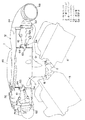
図1〜図3は、この発明に係るV型6気筒内燃機関用の吸気装置の一実施例を示している。この吸気装置は、V型内燃機関のバンク間の上方に配置される偏平な箱状の吸気コレクタ1と、この吸気コレクタ1と各気筒の吸気ポートを接続する下部マニホルド2と、から大略構成されている。上記下部マニホルド2は、図1に示すように、吸気コレクタ1の中央部下面に取り付けられ、左右バンクのシリンダヘッド3,4がこの下部マニホルド2を介して吸気コレクタ1に接続されるようになっている。
1 to 3 show an embodiment of an intake device for a V-type 6-cylinder internal combustion engine according to the present invention. This intake device is generally constituted by a flat box-
上記吸気コレクタ1は、コレクタボディ11とコレクタカバー12との2つの部材に分割して構成されているものであり、コレクタボディ11およびコレクタカバー12のそれぞれは、アルミニウム合金により一体に鋳造されている。図4および図5は、コレクタカバー12を取り外したコレクタボディ11の単体での構成を示している。
The
上記コレクタボディ11は、左右両側に、それぞれ第1コレクタ部13および第2コレクタ部14を備えている。これらのコレクタ部13,14は、気筒列方向(前後方向)に細長い箱状をなしており、互いにほぼ平行に配置されているとともに、それぞれの互いに対向する内側面から互いに内側へ各3本のブランチ部15が延びている。
The
これらの計6本のブランチ部15は、図5に示すように、両コレクタ部13,14の間の領域において、互い違いに組み合わさるような形で並んで配置されており、かつそれぞれの先端部が、吸気コレクタ1の中央部に達している。各ブランチ部15内の通路(ブランチ通路)は、吸気コレクタ1の下面中央部に突出して形成されたブランチ集合部16の下面に、1列に並んで開口している。上記下部マニホルド2は、このブランチ集合部16の下面に取り付けられ、各ブランチ通路を左右に振り分けて、シリンダヘッド3,4の吸気ポートに連通させている。この下部マニホルド2を介して、図1において左側のシリンダヘッド3(右バンク)の♯1,♯3,♯5気筒は、図右側のコレクタ部13に接続され、図右側のシリンダヘッド4(左バンク)の♯2,♯4,♯6気筒は、図左側のコレクタ部14に接続されている。
As shown in FIG. 5, these six
また、2つのコレクタ部13,14の間には、6本のブランチ部15を連ねるように、コレクタ部13,14の下面の高さ位置に沿った底壁17が一体に形成されているとともに、図4に示すように後部壁18が一体に形成されており、これらのコレクタ部13,14と底壁17と後部壁18との内側に、容積室21となる空間が形成されている。この容積室21となる空間の上部には、コレクタ部13,14の上面の高さ位置にほぼ対応した一つの平面に沿って、ほぼ矩形をなす開口フランジ22がボルトボス部23とともに形成されており、ここに上記コレクタカバー12が取り付けられている(図2、図3参照)。詳しくは、上記コレクタカバー12の板状のカバー部41が、液体ガスケット等の適宜なシール材を介して上記開口フランジ22を覆っており、かつ上記ボルトボス部23に螺合する複数本のボルト42により結合されている。これによって、上記の底壁17より上方の空間が、密閉された容積室21となっている。
In addition, a
なお、上記容積室21内には、図4、図5に示すように、コレクタボディ11を下部マニホルド2に固定するためのボルトが貫通する円筒状のボス部25が、ブランチ部15の肉と部分的に連続した形で、6箇所に形成されている。これらのボス部25に配置される図示せぬボルトは、コレクタカバー12を取り付ける前に、容積室21側から締付作業がなされる。
In the
上記第1,第2コレクタ部13,14の後端部には、それぞれ首部13a,14aを介して吸気入口27,28が設けられている。これらの吸気入口27,28は、互いに内側を向くように斜めに傾けて形成されており、矩形のフランジ29,30をそれぞれ備えている。
At the rear end portions of the first and
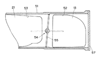
また、コレクタボディ11の前端部には、左右に延びた円筒状の連通管51が設けられている。この連通管51は、第1,第2コレクタ部13,14等と一体に鋳造されたもので、図6に内部構造を示すように、その両端部が、窓状の開口部52を通して、第1,第2コレクタ部13,14の前端部にそれぞれ接続されている。また、この連通管51の長手方向の中間部は、同じく窓状の開口部53を通して、コレクタ部13,14の間の容積室21に開放されている。つまり、実質的に容積室21と一体の室となっている。そして、この連通管51内部を、上記開口部52と上記開口部53との間の位置において遮断するように、バタフライバルブ型の弁体55を備えた開閉弁54が、連通管51の左右にそれぞれ設けられている。なお、上記弁体55の周縁が開閉の際に接触する連通管51の要部の内周面は、鋳造後、部分的に機械加工されている。上記連通管51の断面形状は、真円形に近い長円形をなしており、従って、弁体55の外形状も、同様の長円形をなしている。また、連通管51の両端は、上記の機械加工や弁体55の組立のために、開放された形に鋳造されており、最終的に別体のエンドプレート57をそれぞれ取り付けることによって閉塞されている。
In addition, a
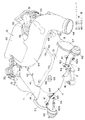
上記開閉弁54は、図2等に示すように、ブラケット61を介して支持される負圧ダイヤフラム式アクチュエータ62を備えており、弁体55のシャフト(図示せず)端部に設けられたリンクプレート63に上記アクチュエータ62のロッド62a先端が連係し、負圧の導入・遮断に応じて開閉動作する。64は、リンクプレート63の回動範囲を規制するストッパピンである。なお、一対の開閉弁54は、基本的に左右対称に構成されており、通常は、両者同時に開閉制御される。
As shown in FIG. 2 and the like, the on-off
また、上記連通管51の中央上面には、ボルト締付作業用の作業孔65が設けられており、この作業孔65が、六角孔を備えたねじ式のプラグ66によって閉塞されている。この作業孔65の直下となる連通管51底部には、前述した下部マニホルド2固定用のボス部25と同様のボス部(図示せず)が位置しており、下部マニホルド2前端部に螺合するボルトが該ボス部に配置されている。つまり、上記のボルトを作業孔65を通して連通管51の外側から締め付けた後に、上記プラグ66を装着することで、密閉されている。なお、下部マニホルド2の後端部に対応するもう1本のボルトが貫通するボス部25Aが、コレクタボディ11の後端部の後部壁18外側に設けられている。従って、コレクタボディ11と下部マニホルド2とは、前述したボス部25に対応する左右3箇所ずつの6箇所と、前後の1箇所ずつとの、計8点で固定されている(図5参照)。
Further, a
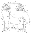
一方、図2、図3に示すように、上記コレクタカバー12においては、上記第1,第2コレクタ部13,14へ吸気を導くための吸気入口管44が、上記カバー部41の上面に一体に鋳造されている。この吸気入口管44は、平面図上で見て略S字状をなすように湾曲しており、下流端部が、コレクタカバー12の後端部に設けられた台形状をなす吸気分岐部45に連続している。そして、吸気分岐部45は、左右に一対の吸気出口部46,47を有し、この吸気出口部46,47と各コレクタ部13,14の吸気入口27,28との間に、スロットル弁を内蔵したスロットルチャンバ31,32がそれぞれ介装されている。このスロットルチャンバ31,32は、上記フランジ29,30に取り付けられており、上記吸気出口部46,47との間は、短いゴムホース33,34によって接続されている。35は、このゴムホース33,34を締め付けるホースクランプを示す。
On the other hand, as shown in FIGS. 2 and 3, in the
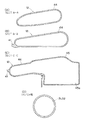
より具体的には、上記吸気入口管44は、図外のエアクリーナに吸気ダクトを介して接続される吸気取入口48が、第1コレクタ部13の側方において前方へ向かって開口しているとともに、ここから略90°湾曲して第1コレクタ部13の上を左右方向に横切り、さらに容積室21上方位置で後方へ略90°湾曲して上記吸気分岐部45へ至る。つまり、第1コレクタ部13の上方から吸気取入口48へ至る上流側部分は、カバー部41から側方へ突出した形に形成されている。また、カバー部41上の湾曲部から下流側部分は、バンク間の中央に沿って、後方へ真っ直ぐに延びている。そして、上記吸気取入口48の部分では略円形の断面形状(図1参照)を有し、かつ図7に示すように、第1コレクタ部13と交差する付近から上下方向の寸法が小さな偏平な形状となっていくとともに、その通路断面積が、吸気分岐部45へ近付くにつれて徐々に拡大するようになっている。また、吸気入口管44の下流端部となる吸気分岐部45は、図7(C)のように、下方へ拡大した拡張部45aを有し、この拡張部45aの側面に、上記吸気出口部46,47が開口している。なお、吸気出口部46と吸気出口部47とは、僅かに異なる高さ位置に配置されているものの、平面図上では、図3に明らかなように、実質的に左右対称となるように形成されている。
More specifically, in the
また、カバー部41から突出した吸気入口管44の上流側部分を支持するために、上記吸気入口管44の中間部の両側に、貫通孔を備えた一対のボス部49が形成されている(図2,図3参照)とともに、第1コレクタ部13の上面に、対応するねじ孔を備えた一対のボルトボス部50が形成されており(図4,図5参照)、図示せぬボルトにより互いに結合されるようになっている。
A pair of
上記のように構成された吸気装置においては、例えば内燃機関が低中速域にあるときには、上記の一対の開閉弁54がそれぞれ閉じられる。これにより、第1コレクタ部13と第2コレクタ部14とが、互いに分離独立したものとなり、かつ容積室21からも切り離された形となる。従って、吸気分岐部45から下流側で左右バンク毎に独立した吸気系が構成されるとともに、吸気分岐部45から各気筒へ至るそれぞれの管長が十分に長く得られ、かつ第1,第2コレクタ部13,14の実質的な容積が小さくなる。これにより、低中速域に適した吸気動的効果が得られ、体積効率の向上により低中速域のトルクが向上する。
In the intake device configured as described above, for example, when the internal combustion engine is in the low and medium speed range, the pair of on-off
また、例えば内燃機関が高速域となると、一対の開閉弁54がそれぞれ図6の仮想線のように開かれ、第1コレクタ部13と第2コレクタ部14とが連通管51により互いに連通するとともに、中央の容積室21とも一体のものとなる。従って、左右バンクの独立した部分の管長は短くなり、かつ各バンクの吸気系が合流する室の容量が非常に大きなものとなる。そのため、高速域に適した吸気動的効果が得られ、高速域の体積効率が向上する。
Further, for example, when the internal combustion engine reaches a high speed range, the pair of on-off
ここで、上記構成では、容積室21の上面を覆うカバー部41と一体に偏平な吸気入口管44が鋳造されているため、カバー部41の膜剛性が向上し、その振動による放射音が低減する。同時に、カバー部41の面積のかなりの部分が偏平な吸気入口管44で覆われて二重構造となるので、内部から生じる透過音も効果的に抑制される。
Here, in the above configuration, since the flat
また、吸気取入口48から流入した吸気の流れは、吸気入口管44の通路断面積が下流へ向かうに従って徐々に拡大し、かつ拡張部45aにおいて大きく拡大することから、流速が徐々に低下していき、かつ拡張部45aにおいて流速が大きく低下した状態でもって左右の吸気出口部46,47へと分配される。しかも、吸気入口管44を後方へと向かう流れの方向が、吸気分岐部45からUターンするような形で、各コレクタ部13,14へ流れる。従って、流れの片寄りが少なくなり、両バンクへ均等に吸気を導入することができるとともに、乱流の発生等による吸気損失を抑制できる。
In addition, the flow of the intake air flowing in from the
さらに、上記構成では、吸気入口管44がコレクタカバー12に一体鋳造されているので、図2,図3等に明らかなように、スロットルチャンバ31,32は、その入口側および出口側の双方が同じ吸気コレクタ1に接続されることになる。従って、内燃機関がロール振動等により振動しても、スロットルチャンバ31,32が片持ち状に振動することはなく、その振動が抑制される。しかも、カバー部41から側方へ突出した吸気入口管44が第1コレクタ部13のボルトボス部50に固定支持されるため、吸気入口管44が振動したり、カバー部41のボルト42に過大な応力が作用したりすることがない。
Further, in the above configuration, since the
なお、図示の実施例は、V型内燃機関を、クランクシャフト軸方向が車両前後方向に沿った形となる、所謂縦置き状態に車両エンジンルームに搭載する場合に好適なものである。つまり、連通管51が車両の前方に、スロットルチャンバ31,32が車両のダッシュボード寄りに位置するものとなる。上記第1実施例では、前方の連通管51の上面位置に比べて、後方の吸気分岐部45の上面は相対的に上方へ張り出しているが、これらによる吸気コレクタ1上面の全体的な傾斜が、エンジンルーム上面を覆うフードの傾斜に対応したものとなる。別体の吸気ダクトが吸気コレクタ1の上方を通る場合と異なり、上記吸気入口管44は吸気コレクタ1と一体に鋳造されたものであるので、余分な隙間を設ける必要はなく、フードとの間の間隙は、非常に小さなものとすることができる。
The illustrated embodiment is suitable when the V-type internal combustion engine is mounted in the vehicle engine room in a so-called vertical state in which the crankshaft axial direction is along the vehicle longitudinal direction. That is, the
1…吸気コレクタ
2…下部マニホルド
3,4…シリンダヘッド
11…コレクタボディ
12…コレクタカバー
15…ブランチ部
21…容積室
27,28…吸気入口
31,32…スロットルチャンバ
41…カバー部
44…吸気入口管
54…開閉弁
DESCRIPTION OF
Claims (3)
上記吸気コレクタは、左右両側にそれぞれ第1,第2コレクタ部を備えるとともに、これらの第1,第2コレクタ部の間に、開閉弁を介して各コレクタ部と連通可能な容積室を備えており、
各コレクタ部の後端部にそれぞれ吸気入口が設けられており、
上記容積室の上面開口を覆って該容積室を構成するカバー部の一部を二重構造とし、この二重構造の部分を吸気入口管の一部とし、
この吸気入口管は、上記二重構造部分では上下方向の寸法が小さい偏平な通路断面形状を有するとともに、上流端となる吸気取入口が一方のコレクタ部の側方に位置し、上流側部分が上記コレクタ部を横切るように、上記カバー部から側方へ突出しつつ上記吸気取入口へと延び、上記容積室の後方に達した下流端部には下方へ拡大した拡張部が設けられ、この拡張部の両側面に吸気出口部が開口しており、
各バンク毎にスロットルチャンバを備え、この一対のスロットルチャンバが、各コレクタ部の吸気入口と上記拡張部の上記吸気出口部との間に各々介装されていることを特徴とするV型内燃機関の吸気装置。 In the intake system for a V-type internal combustion engine in which an intake collector is disposed above the banks of the V-type internal combustion engine and the intake system is switched inside the intake collector.
The intake collector includes first and second collector portions on both the left and right sides, and a volume chamber that can communicate with each collector portion via an on-off valve between the first and second collector portions. And
An intake inlet is provided at the rear end of each collector part,
A part of the cover portion that covers the upper surface opening of the volume chamber and constitutes the volume chamber has a double structure, and a portion of the double structure is a part of the intake inlet pipe,
The intake pipe has a flat passage cross-sectional shape with a small vertical dimension in the double structure portion, and an intake intake port serving as an upstream end is located on the side of one collector portion, and the upstream portion is across the collector section, while projecting from the cover portion to the side extending into the inlet the intake, the downstream end reaching to the rear of the volume chamber extension is provided with an enlarged downward, the extension The intake outlet is open on both sides of the unit,
Each bank is provided with a throttle chamber, and the pair of throttle chambers are respectively interposed between an intake inlet of each collector part and the intake outlet part of the expansion part. Inhalation device.
Priority Applications (1)
| Application Number | Priority Date | Filing Date | Title |
|---|---|---|---|
| JP2003327059A JP4352829B2 (en) | 2003-09-19 | 2003-09-19 | Intake device for V-type internal combustion engine |
Applications Claiming Priority (1)
| Application Number | Priority Date | Filing Date | Title |
|---|---|---|---|
| JP2003327059A JP4352829B2 (en) | 2003-09-19 | 2003-09-19 | Intake device for V-type internal combustion engine |
Publications (2)
| Publication Number | Publication Date |
|---|---|
| JP2005090416A JP2005090416A (en) | 2005-04-07 |
| JP4352829B2 true JP4352829B2 (en) | 2009-10-28 |
Family
ID=34457030
Family Applications (1)
| Application Number | Title | Priority Date | Filing Date |
|---|---|---|---|
| JP2003327059A Expired - Fee Related JP4352829B2 (en) | 2003-09-19 | 2003-09-19 | Intake device for V-type internal combustion engine |
Country Status (1)
| Country | Link |
|---|---|
| JP (1) | JP4352829B2 (en) |
Families Citing this family (1)
| Publication number | Priority date | Publication date | Assignee | Title |
|---|---|---|---|---|
| CN113294273B (en) * | 2021-04-23 | 2024-07-30 | 江门市大长江集团有限公司 | Motorcycle, air filter assembly and air inlet connector |
-
2003
- 2003-09-19 JP JP2003327059A patent/JP4352829B2/en not_active Expired - Fee Related
Also Published As
| Publication number | Publication date |
|---|---|
| JP2005090416A (en) | 2005-04-07 |
Similar Documents
| Publication | Publication Date | Title |
|---|---|---|
| JP4896822B2 (en) | Intake manifold for internal combustion engines | |
| KR101129975B1 (en) | Intake manifold for multi-cylinder internal combustion engine | |
| JP4352829B2 (en) | Intake device for V-type internal combustion engine | |
| JPH03281927A (en) | Air intake device of engine | |
| JP4450403B2 (en) | Intake silencer and outboard motor equipped with the same | |
| JP4305107B2 (en) | Intake device for V-type internal combustion engine | |
| JP2019065750A (en) | Intake system for vehicular internal combustion engine | |
| JP4103749B2 (en) | Intake device for V-type internal combustion engine | |
| JP3617679B2 (en) | V-type multi-cylinder engine intake system | |
| JP3610772B2 (en) | Variable intake system for V-type internal combustion engine | |
| JPH0565857A (en) | Structure for supporting intake manifold | |
| JP4103750B2 (en) | Intake device for V-type internal combustion engine | |
| JP3601640B2 (en) | Intake device for a multi-cylinder internal combustion engine | |
| JP4573714B2 (en) | Intake manifold made of synthetic resin | |
| JP2007009883A (en) | Engine intake control system | |
| JP3675226B2 (en) | Intake device for internal combustion engine | |
| JP3997598B2 (en) | Variable intake system for V-type internal combustion engine | |
| JPS62159725A (en) | Intake device for v-engine | |
| JP4026572B2 (en) | Method for manufacturing intake collector of internal combustion engine and core used therefor | |
| JPS63215822A (en) | Intake device for v-type engine | |
| JPH0541827B2 (en) | ||
| JP4671952B2 (en) | Intake manifold for multi-cylinder internal combustion engines | |
| JPH09250350A (en) | Intake device for internal combustion engine | |
| JP3608666B2 (en) | Supply air cooler for internal combustion engine | |
| JP2842060B2 (en) | Variable intake system for automotive engine |
Legal Events
| Date | Code | Title | Description |
|---|---|---|---|
| A621 | Written request for application examination |
Free format text: JAPANESE INTERMEDIATE CODE: A621 Effective date: 20060727 |
|
| A977 | Report on retrieval |
Free format text: JAPANESE INTERMEDIATE CODE: A971007 Effective date: 20081117 |
|
| A131 | Notification of reasons for refusal |
Free format text: JAPANESE INTERMEDIATE CODE: A131 Effective date: 20081125 |
|
| A521 | Written amendment |
Free format text: JAPANESE INTERMEDIATE CODE: A523 Effective date: 20090109 |
|
| A131 | Notification of reasons for refusal |
Free format text: JAPANESE INTERMEDIATE CODE: A131 Effective date: 20090414 |
|
| A521 | Written amendment |
Free format text: JAPANESE INTERMEDIATE CODE: A523 Effective date: 20090610 |
|
| TRDD | Decision of grant or rejection written | ||
| A01 | Written decision to grant a patent or to grant a registration (utility model) |
Free format text: JAPANESE INTERMEDIATE CODE: A01 Effective date: 20090707 |
|
| A01 | Written decision to grant a patent or to grant a registration (utility model) |
Free format text: JAPANESE INTERMEDIATE CODE: A01 |
|
| A61 | First payment of annual fees (during grant procedure) |
Free format text: JAPANESE INTERMEDIATE CODE: A61 Effective date: 20090720 |
|
| R150 | Certificate of patent or registration of utility model |
Free format text: JAPANESE INTERMEDIATE CODE: R150 |
|
| FPAY | Renewal fee payment (event date is renewal date of database) |
Free format text: PAYMENT UNTIL: 20120807 Year of fee payment: 3 |
|
| FPAY | Renewal fee payment (event date is renewal date of database) |
Free format text: PAYMENT UNTIL: 20120807 Year of fee payment: 3 |
|
| FPAY | Renewal fee payment (event date is renewal date of database) |
Free format text: PAYMENT UNTIL: 20130807 Year of fee payment: 4 |
|
| LAPS | Cancellation because of no payment of annual fees |