JP4352482B2 - Pachinko machine - Google Patents
Pachinko machine Download PDFInfo
- Publication number
- JP4352482B2 JP4352482B2 JP32050298A JP32050298A JP4352482B2 JP 4352482 B2 JP4352482 B2 JP 4352482B2 JP 32050298 A JP32050298 A JP 32050298A JP 32050298 A JP32050298 A JP 32050298A JP 4352482 B2 JP4352482 B2 JP 4352482B2
- Authority
- JP
- Japan
- Prior art keywords
- mounting plate
- safe ball
- pachinko machine
- plate
- ball passage
- Prior art date
- Legal status (The legal status is an assumption and is not a legal conclusion. Google has not performed a legal analysis and makes no representation as to the accuracy of the status listed.)
- Expired - Fee Related
Links
Images


Landscapes
- Pinball Game Machines (AREA)
Description
【0001】
【発明の属する技術分野】
本発明は、パチンコ機に関するものである。
【0002】
【従来の技術】
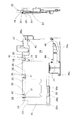
図19は、従来のパチンコ機の背面を示したものである。パチンコ機61は、周囲が外枠62で覆われており、外枠62の内側には、内部に遊技盤(図示せず)を嵌め込み設置したミドル枠63が設置されている。そして、ミドル枠63の後方には、合成樹脂製の機構板64が設置されている。かかる機構板64は、下側中央に、遊技盤に設置された入賞装置に入賞した遊技球を一時的に貯えるためのセーフ球タンク66が設置されている。また、中央下端には、セーフ球排出装置67が設置されており、セーフ球通路68を介してセーフ球タンク66と連通した状態になっている。さらに、それらのセーフ球タンク66およびセーフ球通路68の後方には、パチンコ機61の作動内容を制御する制御装置65が固着されている。一方、パチンコ機61は、パチンコホールの設置島に外枠62のみが固定された状態で設置されており、その外枠62に対して、ミドル枠63が片開き自在に取り付けられており、さらに、そのミドル枠63に対して、機構板64が片開き自在にになっている。
【0003】
【発明が解決しようとする課題】
しかしながら、上記パチンコ機61は、セーフ球タンク66やセーフ球通路68内で遊技球が詰まる(凝集する)等のトラブルが発生した場合には、ミドル枠63を片開きした上で、さらに、機構板64を片開きして、セーフ球タンク66やセーフ球通路68を露出させなければ、かかるトラブルを解消することができない。このため、トラブルの解消に多大なスペースを要し、遊技者に迷惑をかけることが多かった。
【0004】
本発明の目的は、上記従来のパチンコ機が有する課題を解消し、セーフ球タンクやセーフ球通路内でトラブルが発生した場合でも、そのトラブルを容易に解消することができる実用的なパチンコ機を提供することにある。
【0005】
【課題を解決するための手段】
本発明のうち、請求項1に記載された発明の構成は、周囲が外枠で覆われており、その外枠の内側に、遊技盤を取り付けたミドル枠が設置されており、そのミドル枠の裏面側に、セーフ球タンクとセーフ球通路とを上下に連設した機構板が設置されているとともに、それらのミドル枠と機構板とが、外枠に対して片開き自在に取り付けられており、かつ、前記セーフ球タンクおよびセーフ球通路の後方に、作動内容を制御する制御装置が設置されているパチンコ機であって、前記セーフ球タンクおよびセーフ球通路の後方に、取付板が、上端縁を軸として片開き自在、且つ、軸方向へスライド可能に設置されており、前記制御装置がその取付板を介して設置されている一方、前記機構板に、前記取付板を所定角度に傾斜させた状態で支持する支持部材を付設するとともに、前記取付板に、上下方向へ延びる補強リブを設け、当該補強リブの上端における前記取付板の表面との段差を前記支持部材に係合可能な係合屈曲部とし、前記取付板を所定角度以上片開きした状態で前記軸方向へスライドさせ、前記係合屈曲部を前記支持部材に係合させることにより、前記取付板が所定角度片開きされた状態で支持されることにある。また、請求項2に記載された発明の構成は、請求項1に記載された発明において、支持部材が、取付板を、鉛直線と約90度以上の角度をなすように傾斜させた状態で支持するものであることにある。さらに、請求項3に記載された発明の構成は、請求項1に記載された発明、請求項2に記載された発明において、機構板に水平ロール状ガイドが設けられており、その水平ロール状ガイドの右側および/または左側に支持部材が付設されているとともに、取付板に、水平ロール状ガイドより幅広なガイド挿通孔と、柱状部とが上下に連設されており、取付板が、柱状部を水平ロール状ガイド内に嵌入し、ガイド挿通孔に水平ロール状ガイドおよび支持部材を挿通させた状態で、機構板に設置されていることにある。加えて、請求項4に記載された発明の構成は、請求項1〜請求項3に記載された発明において、セーフ球通路にセーフ球通路カバーが着脱自在に設けられていることにある。
【0006】
【発明の実施の形態】
以下、本発明のパチンコ機の一実施形態について、図面に基づいて詳細に説明する。
【0007】
図1は、パチンコ機の正面図であり、パチンコ機1は、周囲が外枠2によって覆われている。そして、前面の上方に、ガラス板4を嵌め込んだ前枠3が片開き自在に設置されており、その前枠3が、各種の入賞装置等を設置した遊技盤(図示せず)の前方に位置した状態になっている。また、前枠3の下側には、供給皿6を突設した中扉5が片開き自在に取り付けられており、中扉5の下側には、貯留皿8および操作ハンドル9を突設した下側機能部7が設置されている。
【0008】
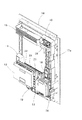
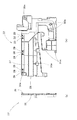
一方、図2は、パチンコ機1の背面図であり、外枠2の内側には、金属製のミドル枠10が設置されている。また、ミドル枠10の後方には、合成樹脂製の機構板11が、前面(パチンコ機1の前面側から見た場合の前面)の一部を、ミドル枠10の後面(パチンコ機1の前面側から見た場合の後面)に当接させた状態で設置されている。そして、それらのミドル枠10および機構板11は、外枠2の左端縁(パチンコ機1の前面側から見た場合の左端縁)に、一体となって片開きできるように固着されている。図3は、ミドル枠10および機構板11を示す後方斜視図であり、図4は、ミドル枠10および機構板11を示す分解斜視図である。機構板11は、右側部材20、下側部材21、カバー部材22、セーフ球通路カバー25等によって、略L字状に組み立て形成されている。そして、右側部材20は、上端に設けられた基板取付凹部24内に、ターミナル基板16が設置されており、そのターミナル基板16の下側に、通路部材17a,17b、遊技球払出装置18等が上下に連設されている。加えて、右側部材20の左上方には、遊技球タンク15が付設されており、通路部材17aと連通した状態になっている。
【0009】
また、図18は、右側部材20と下側部材21とを組み付けた状態を示したものであり、下側部材21の中央上方には、セーフ球タンク50が設けられており、中央下端には、セーフ球排出装置19等が設置されている。そして、それらのセーフ球タンク50とセーフ球排出装置19とが、セーフ球通路53を介して連通した状態になっている。さらに、セーフ球タンク50、セーフ球通路53の後方には、それぞれ、カバー部材22、セーフ球通路カバー25が取り付けられている(図4参照)。加えて、カバー部材22の後方には、取付板23が取り付けられており、その取付板23には、制御装置12およびサブ基板13が設置されている。
【0010】
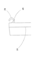
図5、図6は、カバー部材22を示したものであり、カバー部材22は、合成樹脂によって、ほぼ平板状に形成されており、その平板部26には、ほぼ格子状に補強リブ27,27・・が立設されている。さらに、平板部26の上端際には、3つの水平ロール状ガイド28,28・・が、平板部26の後面(パチンコ機1の前面側から見た場合の後面)から後方へ突出するように設けられている。図7は、図5における水平ロール状ガイド28の突設部位を拡大して示したものであり、各水平ロール状ガイド28,28・・は、上側の部分が、開口した状態になっている。また、各水平ロール状ガイド28,28・・は、左右両側に支持部材29,29が添設されており、平板部26の後面から後方へ(補強リブ27,27・・より後方へ)突出した状態になっている。さらに、平板部26の周縁際には、複数の係着孔30a,30a・・が穿設されている。
【0011】
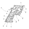
一方、図8、図9、図23は、取付板23を示したものであり、取付板23は、合成樹脂によって、ほぼ平板状に形成されている。そして、上端際に、3つのガイド挿通孔31,31・・が穿設されており、それらのガイド挿通孔31,31・・の上端には、それぞれ、柱状部32,32・・が設けられている。また、図24は、図23におけるB部分を拡大して示したものであり、図20は、図8(a)におけるA−A線断面を拡大して示したものである。各柱状部32,32・・は、完全な円柱状に形成されておらず、それぞれ、長さ方向に沿った窪み59が設けられている。さらに、各柱状部32,32・・の後端縁は、平板部33の後端縁より、わずかに後方に位置した状態になっているとともに、各ガイド挿通孔31,31・・の周囲に設けられた補強リブ34の上端際(柱状部32の設置部位際)に、段差Lが設けられている(以下、各ガイド挿通孔31,31・・の周囲に設けられた補強リブ34における段差Lを形成している屈曲部分を係合屈曲部55という)。加えて、図8、図9に示されるように、平板部33の右側(パチンコ機1の背面側から見た場合の右側)には、サブ基板設置領域39が設けられており、そのサブ基板設置領域39の四隅には、断面L字状の係止爪40,40・・が、先端を内側に向けた状態で突設されている。また、取付板23の左側の下端際には、嵌合凹部35が設けられており、その嵌合凹部35の左右両側には、係着孔30b,30bが穿設されている。さらに、それらの嵌合凹部35、設置用孔30b,30bを覆うように、収納ガイド51が、平板部33の後面(パチンコ機1の前面側から見た場合の後面)から突出するように設けられており、その収納ガイド51内に、左右に係着孔30d,30dを設けた押止部材38が収納されている。なお、押止部材38の裏面には、嵌合凹部35と嵌合する嵌合凸部(図示せず)が設けられている。
【0012】
また、図10は、下側部材21のセーフ球タンク50、セーフ球通路53の後方に、それぞれ、カバー部材22、セーフ球通路カバー25が取り付けられた状態を示したものであり、カバー部材22およびセーフ球通路カバー25は、それぞれ、係着孔30a,30a・・の穿設部分が、係着部材41,41・・により、下側部材21に穿設された係着孔30e,30e・・の穿設部分に係着されることによって、着脱自在に取り付けられている。なお、係着部材41,41・・は、先端が分割されたリング体41aの内部に押込体41bを挿通させたものであり、押込体41bを押し込むと、リング体41aの先端部が膨出し、押込体41bを引き出すと、リング体41aの先端部が元通りに復元するようになっている。このため、カバー部材22あるいはセーフ球通路カバー25の係着孔30a,30a・・と下側部材21の係着孔30e,30e・・とに、係着部材41のリング体41aを挿入し、その状態で、押込体41bを押し込むと、係着孔30a,30a・・の穿設部分と係着孔30e,30e・・の穿設部分とが係着され、押込体41bを引き出すと、係着が解除される。
【0013】
さらに、図11は、カバー部材22の後方に取付板23が取り付けられた状態を示したものであり、図12は、後方に取付板23が取り付けられたカバー部材22を示したものである。取付板23は、各柱状部32,32・・を、カバー部材22の水平ロール状ガイド28,28・・内に嵌入し、各ガイド挿通孔31,31・・に、水平ロール状ガイド28および水平ロール状ガイド28の左右両側に付設された支持部材29,29を挿通させ、かつ、係着部材41,41により、下端の係着孔30c,30cの穿設部分を、下側部材21の係着孔30e、およびカバー部材22の係着孔30aの穿設部分と係着することによって、上端縁を軸として片開き自在に、カバー部材22の後方に設置されている。なお、図10の如く、下側部材21の右側(パチンコ機1の背面側から見た場合の右側)には、下側部材21を縦断するように配線ダクト57が屈曲状に設けられているが、カバー部材22に後方に取り付けられた取付板23によって、後方からほとんど見えないようになっている。
【0014】
一方、図13は、制御装置12を示したものであり、制御装置12は、保護容器44の下端縁のやや左側(パチンコ機1の背面側から見た場合の左側)に、固定孔43を穿設した設置用突起42が突設されている。そして、制御装置12は、図14の如く、設置用突起42を取付板23の押止部材38と平板部33との間に挿入し、設置用突起42の固定孔43に、押止部材38の裏面に突設された嵌合凸部を嵌入させた状態で、押止部材38の係着孔30d,30d穿設部分と平板部33の係着孔30b,30b穿設部分とを、係着部材41,41により係着することによって、着脱自在に取付板23に取り付けられている。
【0015】
加えて、図17は、ターミナル基板16を示したものであり、ターミナル基板16は、第2基板49を収容した第2容器47の前面に、第1基板48を収容した第1容器46を片開き自在に取り付けた二層構造を有している。一方、図18の如く、右側部材20の基板収納凹部24には、弾性係合片56が一体的に設けられており、ターミナル基板16は、その弾性係合片56を第1容器46の左端縁に設けられた係合凹部54に係合させることによって、着脱自在に右側部材20に設置されている。
【0016】
かかるパチンコ機1においては、遊技中に、遊技盤に設置された入賞装置に遊技球が入賞すると、遊技球タンク15に貯えられた遊技球が、通路部材17内を流下し、遊技球払出装置18によってカウントされた後に、賞品球として、供給皿6へ払い出される。一方、入賞装置に入賞した遊技球は、一時的に、セーフ球タンク50内に貯えられ、セーフ球排出装置19によってカウントされた後に外部へ排出される。
【0017】
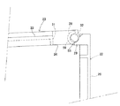
また、取付板23の下端に設けられた係着孔30c,30cを取り外すことによって、取付板23を、その上端縁を軸として片開きすることができる。さらに、取付板23を90度以上片開きすると、各水平ロール状ガイド28の左右両側の支持部材29,29が、各ガイド挿通孔31,31・・の外側に位置した状態となるため、取付板23を右側あるいは左側にスライドさせることが可能となる(なお、図21は、取付板23を左側にスライドさせた状態を示したものである)。さらに、図22は、図21におけるD−D線断面を示したものであり、取付板23を右側あるいは左側にスライドさせると、各支持部材29,29・・が各ガイド挿通孔31,31・・穿設部位の周囲に設けられた係合屈曲部55と係合し合う。このため、取付板23が、略水平に片開きされた状態で保持される(図16参照)。なお、各ガイド挿通孔31,31・・は、水平ロール状ガイド28の幅と左右両側の支持部材29,29の幅とを合わせた長さよりも幅広に形成されているため、取付板23を片開きするだけでスライドさせない場合や、取付板23を90度より小さい角度で片開きする場合には、各支持部材29,29・・が係合屈曲部55と係合せず(図12参照)、取付板23は、片開きした状態で保持されない。
【0018】
また、図15は、取付板23のサブ基板設置領域39へのサブ基板13の設置状態を示したものであり、サブ基板13は、上端縁および下端縁の左右両端から上方および下方へ突設された設置爪45,45・・を、それぞれ、サブ基板設置領域39の四隅に突設された係止爪40,40・・の内部に挿入させることによって、取付板23に設置されている。このため、取付板23を片開きした場合には、サブ基板13を右側(パチンコ機1の背面から見た場合の右側)にスライドさせるだけで、サブ基板13を取付板23から簡単に取り外すことができる。なお、下側部材21の右下方には、せき止め部材58が、閉じた取付板23のサブ基板設置領域39における平板部33より後方へ突出するように設けられているので、取付板23が閉じている場合には、サブ基板13を取り外すことができない。
【0019】
パチンコ機1は、上記の如く、セーフ球タンク50およびセーフ球通路53の後方に、取付板23が、上端縁を軸として片開き自在に設置されており、制御装置12がその取付板23を介して設置されているとともに、カバー部材22に、取付板23を所定角度に傾斜させた状態で支持する支持部材29,29・・が付設されているため、セーフ球タンク50やセーフ球通路53内で遊技球が詰まる等のトラブルが発生した場合でも、ミドル枠10および機構板11を一体的に片開きして、取付板23を傾斜状態で保持するだけで、大きな作業スペースを必要とすることなく、そのトラブルを簡単に解消することができる。しかも、支持部材29,29・・によって、取付板23が略水平に片開きした状態で保持されるため、セーフ球タンク50やセーフ球通路53内におけるトラブルの解消が、非常に容易なものとなっている。
【0020】
また、パチンコ機1は、上述の如く、カバー部材22に水平ロール状ガイド28,28・・が設けられており、それらの水平ロール状ガイド28,28・・の左右両側に、それぞれ支持部材29,29が付設されているとともに、取付板23に、各水平ロール状ガイド28,28・・より幅広なガイド挿通孔31,31・・と、柱状部32,32・・とが、それぞれ上下に連設されており、取付板23が、各柱状部32,32・・を各水平ロール状ガイド28,28・・内に嵌入し、各ガイド挿通孔31,31・・に、各水平ロール状ガイド28,28・・および左右に付設された各支持部材29,29を挿通させた状態で、カバー部材22に設置されており、取付板23を90度以上片開きした状態で、右側あるいは左側にスライドさせると、各支持部材29,29・・が、各ガイド挿通孔31,31・・の周囲に設けられた係合屈曲部55と係合し合って、取付板23が略水平に片開きされた状態で保持される。かかる如く、パチンコ機1は、取付板23を水平より大きい角度で片開きして左右いずれかにスライドさせるだけで、きわめて容易に傾斜状態で保持することができるので、セーフ球タンク50やセーフ球通路53におけるトラブルを、きわめて容易に解消することができる。
【0021】
さらに、パチンコ機1は、各ガイド挿通孔31,31・・の周囲に設けられた補強リブ34の上端際(柱状部32の設置部位際)に段差Lが設けられており、各支持部材29,29・・を係合屈曲部55,55・・に係合させた状態で、取付板23が略水平に保持されるので、略水平に保持された取付板23ががたついたりしない。加えて、取付板23の開閉時における各水平ロール状ガイド28,28・・・・内での柱状部32,32・・の回転中心が、カバー部材22の平板部33の後端縁より、わずかに後方に位置した状態になっているので、取付板23を非常にスムーズに片開きすることができる。その上、取付板23の各柱状部32,32・・が完全な円柱状ではなく、長さ方向に沿った窪み59を有しているので、製造時や修理・交換等のメンテナンス時における取付板23の着脱の際の各水平ロール状ガイド28,28・・・・内への各柱状部32,32・・の挿入が非常に容易である。
【0022】
加えて、パチンコ機1は、セーフ球通路53にセーフ球通路カバー25が着脱自在に設けられているため、取付板23を傾斜状態で保持した上で、セーフ球通路カバー25を取り外すだけで、簡単にセーフ球通路53が露出する。このため、セーフ球タンク50やセーフ球通路53におけるトラブルを、ごく短時間のうちに解消することができる。
【0023】
また、パチンコ機1は、制御装置12が、保護容器44の下端縁に設けられた設置用突起42を、取付板23の押止部材38と平板部33との間に挿入した状態で、押止部材38と平板部33とを係着することによって、着脱自在に取付板23に取り付けられているため、制御装置12を取り替える場合やチェックする場合等に、非常に容易に制御装置12を取り外すことができる。また、パチンコ機1は、サブ基板13が、上端縁および下端縁の左右両端に突設された設置爪45,45・・を、それぞれ、取付板23に突設された断面L字状の係止爪40,40・・の内部に挿入させることによって、着脱自在に取付板23に設置されているため、サブ基板13をチェックする場合やサブ基板13が故障した場合等に、非常に容易にサブ基板13を取り外すことができる。その上、パチンコ機1は、下側部材21に設けられた配線ダクト57が、カバー部材22の後方に取り付けられた取付板23によって、後方からほとんど見えないようになっており、美観にも優れている。一方、パチンコ機1は、機構板11の右上方に設置されるターミナル基板16が、二層構造を有しており、容積の小さい基板収納凹部24内に、非常にコンパクトに収納されている。このため、パチンコ機1の図柄表示装置14や遊技球タンク15は、従来よりも大きなものとなっている。したがって、パチンコ機1は、従来のパチンコ機に比べて、図柄表示装置14による図柄やメッセージの表示がよりダイナミックなものとなっているし、多くの賞品球が払い出される場合でも遊技球タンク15内の遊技球がなくなりにくい。
【0024】
なお、本発明のパチンコ機の構成は、上記実施形態の態様に何ら限定されるものではなく、外枠、ミドル枠、前枠、中扉、下側機能部、機構板(右側部材、下側部材、カバー部材、セーフ球通路カバー)、取付板、通路部材、遊技球払出装置、セーフ球排出装置、遊技球タンク、係着部材等の形状・構造等の構成を必要に応じて適宜変更することができる。
【0025】
たとえば、機構板は、右側部材、下側部材、カバー部材、セーフ球通路カバー等によって、組み立て形成されるものに限定されず、一体的に形成されたものでも良い。また、機構板に設ける水平ロール状ガイドや取付板に設ける柱状部の個数は、3個に限定されず、2個以下でも良いし、4個以上でも良い。さらに、支持部材は、必ずしも、水平ロール状ガイドの左右両側に付設する必要はなく、水平ロール状ガイドの左右いずれか片側に付設することも可能であるし、場合によっては、水平ロール状ガイドの側部以外の部位に設けることも可能である。加えて、パチンコ機は、取付板を所定の1つの角度で傾斜させた状態で支持する支持部材が機構板に付設されたものに限定されず、たとえば、水平ロール状ガイドの左右両側に、長さの異なる支持部材を付設する方法等を採用することによって、取付板を所定の2つの角度で傾斜させた状態で支持する支持部材が機構板に付設されたもの等に変更することもできる。かかる構成を採用した場合には、パチンコ機は、必要に応じて取付板の角度を変更できるものとなり、セーフ球タンクやセーフ球通路におけるトラブルを一層容易に解消できるものとなる。また、支持部材は、上記実施形態の如く、カバー部材の平板部から一体的に突出したものに限定されず、基端がカバー部材の後面に遊嵌されており先端が取付板の前面と係合可能な棒状体(自動車のボンネットを片開きした状態で保持する支持部材の如き形状を有するもの)等の他の形状を有するものに変更することも可能である。加えて、パチンコ機は、取付板に水平ロール状ガイドが設けられているとともに、機構板にガイド挿通孔と柱状部とが上下に連設されており、取付板が、水平ロール状ガイド内に柱状部を嵌入させ、水平ロール状ガイドをガイド挿通孔に挿通した状態で、上端縁を中心として片開き自在に機構板に設置されたものでも良い。一方、取付板は、制御装置とサブ基板とを一緒に設置するものに限定されず、制御装置とサブ基板とを別々に設置するものでも良い。また、ターミナル基板は、二層構造を有するものに限定されず、三層構造や四層構造を有するものでも良い。
【0026】
【発明の効果】
請求項1に記載されたパチンコ機は、取付板が、機構板に、上端縁を軸として片開き自在に設置されているとともに、該取付板に係合屈曲部が設けられており、かつ、機構板に、取付板を所定角度に傾斜させた状態で支持する支持部材が付設されているため、セーフ球タンクやセーフ球通路内で遊技球が詰まる等のトラブルが発生した場合でも、ミドル枠および機構板を一体的に片開きして、係合屈曲部を支持部材に係合させて取付板を傾斜状態で保持するだけで、大きな作業スペースを必要とすることなく、そのトラブルを簡単に解消することができる。
また、取付板が軸方向へスライド可能に設置されているため、取付板を所定角度以上片開きした状態で軸方向へスライドさせるだけで、きわめて容易に取付板を傾斜状態で支持することができる。
【0027】
請求項2に記載されたパチンコ機は、支持部材が、取付板を、鉛直線と約90度以上の角度をなすように傾斜させた状態で支持するものであるので、セーフ球タンクやセーフ球通路におけるトラブルを非常に容易に解消することができる。
【0028】
請求項3に記載されたパチンコ機は、機構板に水平ロール状ガイドが設けられており、その水平ロール状ガイドの右側および/または左側に支持部材が付設されているとともに、取付板に、水平ロール状ガイドより幅広なガイド挿通孔と、柱状部とが上下に連設されており、取付板が、柱状部を水平ロール状ガイド内に嵌入し、ガイド挿通孔に水平ロール状ガイドおよび支持部材を挿通させた状態で、機構板に設置されており、取付板を開放した状態で、右側あるいは左側にスライドさせると、支持部材が、ガイド挿通孔の隣接部分と係合し合うため、きわめて容易に取付板を傾斜状態で保持することができ、セーフ球タンクやセーフ球通路におけるトラブルを、きわめて容易に解消することができる。
【0029】
請求項4に記載されたパチンコ機は、セーフ球通路にセーフ球通路カバーが着脱自在に設けられているため、取付板を傾斜状態で保持した上で、セーフ球通路カバーを取り外すだけで、簡単にセーフ球通路が露出する。このため、セーフ球タンクやセーフ球通路におけるトラブルを、ごく短時間のうちに解消することができる。
【図面の簡単な説明】
【図1】パチンコ機の正面図である。
【図2】パチンコ機の背面図である。
【図3】ミドル枠および機構板をパチンコ機の背面側から示す斜視図である。
【図4】ミドル枠および機構板をパチンコ機の背面側から示す分解斜視図である。
【図5】(a),(b)は、それぞれ、パチンコ機の背面側から見たカバー部材の正面図、左側面図である。
【図6】カバー部材をパチンコ機の背面側から示す斜視図である。
【図7】図5の部分拡大図である。
【図8】(a),(b)は、それぞれ、パチンコ機の背面側から見た取付板の正面図、左側面図である。
【図9】(a),(b)は、それぞれ、取付板をパチンコ機の背面側から示す斜視図、部分分解斜視図である。
【図10】ミドル枠および機構板(カバー部材が取り付けられている状態)をパチンコ機の背面側から示す斜視図である。
【図11】ミドル枠および機構板(取付板が取り付けられている状態)をパチンコ機の背面側から示す斜視図である。
【図12】(a),(b)は、それぞれ、取付板を取り付けたカバー部材をパチンコ機の背面側から見た場合の正面図、右側面図である。
【図13】パチンコ機の背面側から見た制御装置の正面図である。
【図14】(a)は、制御装置を取り付けた取付板をパチンコ機の背面側から見た場合の正面図であり、(b)は、(a)におけるC−C線断面を示す説明図である。
【図15】サブ基板を取付板へ設置する様子を示す説明図である。
【図16】取付板を傾斜させた状態を示す説明図である。
【図17】ターミナル基板を示す説明図である。
【図18】右側部材および下側部材をパチンコ機の背面側から示す斜視図である。
【図19】従来のパチンコ機の背面図である。
【図20】図8(a)におけるA−A線断面を拡大して示す説明図である。
【図21】取付板を90度以上片開きして左側(パチンコ機の前面側から見た場合の左側)にスライドさせた状態を示す説明図である。
【図22】図21におけるD−D線断面を示す説明図である。
【図23】パチンコ機の正面側から見た取付板の正面図である。
【図24】図23におけるB部分を拡大して示す説明図である。
【符号の説明】
1・・パチンコ機、2・・外枠、3・・前枠、4・・ガラス板、5・・中扉、6・・供給皿、7・・下側機能部、8・・貯留皿、9・・操作ハンドル、10・・ミドル枠、11・・機構板、12・・制御装置、13・・サブ基板、14・・図柄表示装置、15・・遊技球タンク、16・・ターミナル基板、17a,17b・・通路部材、18・・遊技球払出装置、19・・セーフ球排出装置、20・・右側部材、21・・下側部材、22・・カバー部材、23・・取付板、24・・基板取付凹部、25・・セーフ球通路カバー、26・・平板部、27・・補強リブ、28・・水平ロール状ガイド、29・・支持部材、30a〜30e・・係着孔、31・・ガイド挿通孔、32・・柱状部、33・・平板部、34・・補強リブ、35・・嵌合凹部、38・・押止部材、39・・サブ基板設置領域、40・・係止爪、41・・係着部材、42・・設置用突起、43・・固定孔、44・・保護容器、45・・設置爪、46・・第1収容部、47・・第2収容部、48・・第1基板、49・・第2基板、50・・セーフ球タンク、51・・収納ガイド、53・・セーフ球通路、54・・係合凹部、55・・係合屈曲部、56・・弾性係合片、57・・配線ダクト、58・・せき止め部材、59・・窪み、61・・パチンコ機、62・・外枠、63・・ミドル枠、64・・機構板、65・・制御装置、66・・セーフ球タンク、67・・セーフ球排出装置、68・・セーフ球通路。[0001]
BACKGROUND OF THE INVENTION
The present invention relates to a pachinko machine.
[0002]
[Prior art]
FIG. 19 shows the back of a conventional pachinko machine. The periphery of the
[0003]
[Problems to be solved by the invention]
However, the
[0004]
An object of the present invention is to solve the problems of the conventional pachinko machine and to provide a practical pachinko machine that can easily solve the trouble even when a trouble occurs in the safe ball tank or the safe ball passage. It is to provide.
[0005]
[Means for Solving the Problems]
Among the present inventions, the configuration of the invention described in
[0006]
DETAILED DESCRIPTION OF THE INVENTION
Hereinafter, an embodiment of a pachinko machine according to the present invention will be described in detail with reference to the drawings.
[0007]
FIG. 1 is a front view of a pachinko machine, and the periphery of the
[0008]
On the other hand, FIG. 2 is a rear view of the
[0009]
FIG. 18 shows a state in which the
[0010]
5 and 6 show the
[0011]
On the other hand, FIG. 8, FIG. 9, and FIG. 23 show the mounting
[0012]
FIG. 10 shows a state in which the
[0013]
Further, FIG. 11 shows a state where the mounting
[0014]
On the other hand, FIG. 13 shows the
[0015]
In addition, FIG. 17 shows the
[0016]
In such a
[0017]
Further, by removing the engaging
[0018]
FIG. 15 shows the installation state of the
[0019]
In the
[0020]
Further, as described above, the
[0021]
Further, the
[0022]
In addition, since the safe
[0023]
Further, the
[0024]
In addition, the structure of the pachinko machine of the present invention is not limited to the aspect of the above-described embodiment. The outer frame, the middle frame, the front frame, the inner door, the lower functional unit, the mechanism plate (the right member, the lower side) Members, cover members, safe ball passage covers), mounting plates, passage members, game ball payout devices, safe ball discharge devices, game ball tanks, engaging members, etc. be able to.
[0025]
For example, the mechanism plate is not limited to one that is assembled and formed by a right side member, a lower side member, a cover member, a safe ball passage cover, and the like, and may be formed integrally. The number of horizontal roll guides provided on the mechanism plate and the number of columnar portions provided on the mounting plate is not limited to three, and may be two or less, or four or more. Furthermore, the support member does not necessarily have to be attached to the left and right sides of the horizontal roll guide, and can be attached to either the left or right side of the horizontal roll guide. It is also possible to provide in parts other than a side part. In addition, the pachinko machine is not limited to those in which the support member that supports the mounting plate in a state where the mounting plate is inclined at a predetermined angle is attached to the mechanism plate. By adopting a method of attaching different support members, the support member that supports the attachment plate in a state where the attachment plate is inclined at two predetermined angles can be changed to one attached to the mechanism plate. When such a configuration is adopted, the pachinko machine can change the angle of the mounting plate as required, and troubles in the safe ball tank and the safe ball passage can be solved more easily. Further, the support member is not limited to one integrally protruding from the flat plate portion of the cover member as in the above embodiment, and the base end is loosely fitted to the rear surface of the cover member, and the front end is engaged with the front surface of the mounting plate. It is also possible to change it to one having another shape such as a rod-like body that can be joined (having a shape such as a support member that holds the bonnet of an automobile in a state where it is opened in one piece). In addition, the pachinko machine is provided with a horizontal roll guide on the mounting plate, and a guide insertion hole and a columnar portion are connected to the mechanism plate vertically, and the mounting plate is placed in the horizontal roll guide. It may be installed on the mechanism plate so that it can be opened in a single-sided manner with the upper end edge as the center in a state where the columnar portion is inserted and the horizontal roll guide is inserted through the guide insertion hole. On the other hand, the mounting plate is not limited to the one in which the control device and the sub board are installed together, and may be one in which the control device and the sub board are installed separately. The terminal board is not limited to the one having a two-layer structure, and may have a three-layer structure or a four-layer structure.
[0026]
【The invention's effect】
In the pachinko machine according to
In addition, since the mounting plate is installed so as to be slidable in the axial direction, the mounting plate can be supported in an inclined state by simply sliding the mounting plate in the axial direction with the mounting plate opened by a predetermined angle or more. .
[0027]
In the pachinko machine according to
[0028]
In the pachinko machine described in claim 3, a horizontal roll guide is provided on the mechanism plate, and support members are provided on the right side and / or left side of the horizontal roll guide, and the mounting plate is provided with a horizontal roll guide. A guide insertion hole that is wider than the roll-shaped guide and a columnar portion are connected vertically, and the mounting plate fits the columnar portion into the horizontal roll-shaped guide, and the horizontal roll-shaped guide and support member are inserted into the guide insertion hole. It is installed on the mechanism plate in the inserted state, and when the slide is moved to the right or left side with the mounting plate opened, the support member engages with the adjacent part of the guide insertion hole, so it is very easy The mounting plate can be held in an inclined state, and troubles in the safe ball tank and the safe ball passage can be solved very easily.
[0029]
In the pachinko machine according to
[Brief description of the drawings]
FIG. 1 is a front view of a pachinko machine.
FIG. 2 is a rear view of the pachinko machine.
FIG. 3 is a perspective view showing the middle frame and the mechanism plate from the back side of the pachinko machine.
FIG. 4 is an exploded perspective view showing the middle frame and the mechanism plate from the back side of the pachinko machine.
FIGS. 5A and 5B are a front view and a left side view, respectively, of a cover member viewed from the back side of the pachinko machine.
FIG. 6 is a perspective view showing the cover member from the back side of the pachinko machine.
FIG. 7 is a partially enlarged view of FIG. 5;
FIGS. 8A and 8B are a front view and a left side view, respectively, of the mounting plate viewed from the back side of the pachinko machine.
9A and 9B are a perspective view and a partially exploded perspective view, respectively, showing the mounting plate from the back side of the pachinko machine.
FIG. 10 is a perspective view showing a middle frame and a mechanism plate (with a cover member attached) from the back side of the pachinko machine.
FIG. 11 is a perspective view showing the middle frame and the mechanism plate (with the attachment plate attached) from the back side of the pachinko machine.
12A and 12B are a front view and a right side view, respectively, when the cover member to which the mounting plate is attached is viewed from the back side of the pachinko machine.
FIG. 13 is a front view of the control device viewed from the back side of the pachinko machine.
14A is a front view of a mounting plate with a control device attached when viewed from the back side of the pachinko machine, and FIG. 14B is an explanatory view showing a cross section taken along the line CC in FIG. It is.
FIG. 15 is an explanatory diagram showing a state in which a sub-board is installed on a mounting plate.
FIG. 16 is an explanatory view showing a state in which the mounting plate is inclined.
FIG. 17 is an explanatory view showing a terminal board.
FIG. 18 is a perspective view showing the right side member and the lower side member from the back side of the pachinko machine.
FIG. 19 is a rear view of a conventional pachinko machine.
FIG. 20 is an explanatory view showing, on an enlarged scale, a cross section taken along line AA in FIG.
FIG. 21 is an explanatory view showing a state in which the mounting plate is opened by 90 degrees or more and is slid to the left side (left side when viewed from the front side of the pachinko machine).
22 is an explanatory diagram showing a cross section taken along line DD in FIG. 21. FIG.
FIG. 23 is a front view of the mounting plate as seen from the front side of the pachinko machine.
24 is an explanatory diagram showing an enlargement of a portion B in FIG. 23. FIG.
[Explanation of symbols]
1 ...
Claims (4)
前記セーフ球タンクおよびセーフ球通路の後方に、取付板が、上端縁を軸として片開き自在、且つ、軸方向へスライド可能に設置されており、前記制御装置がその取付板を介して設置されている一方、
前記機構板に、前記取付板を所定角度に傾斜させた状態で支持する支持部材を付設するとともに、前記取付板に、上下方向へ延びる補強リブを設け、当該補強リブの上端における前記取付板の表面との段差を前記支持部材に係合可能な係合屈曲部とし、
前記取付板を所定角度以上片開きした状態で前記軸方向へスライドさせ、前記係合屈曲部を前記支持部材に係合させることにより、前記取付板が所定角度片開きされた状態で支持されることを特徴とするパチンコ機。The outer frame is covered with an outer frame, and a middle frame with a game board is installed inside the outer frame. A safe ball tank and a safe ball passage are connected vertically on the back side of the middle frame. The mechanism plate is installed, and the middle frame and the mechanism plate are attached to the outer frame so as to be freely openable and operate behind the safe ball tank and the safe ball passage. A pachinko machine equipped with a control device that controls the contents,
A mounting plate is installed behind the safe ball tank and the safe ball passage so that it can be opened in one direction with the upper edge as an axis and is slidable in the axial direction, and the control device is installed through the mounting plate. While
The mechanism plate is provided with a support member for supporting the mounting plate in a state where the mounting plate is inclined at a predetermined angle. The mounting plate is provided with a reinforcing rib extending in the vertical direction, and the mounting plate at the upper end of the reinforcing rib is provided. The step with the surface is an engagement bent portion that can be engaged with the support member,
The mounting plate is supported in a state where the mounting plate is opened by a predetermined angle by sliding the mounting plate in the axial direction in a state where the mounting plate is opened by a predetermined angle or more and by engaging the engagement bent portion with the support member. A pachinko machine characterized by that.
取付板が、柱状部を水平ロール状ガイド内に嵌入し、ガイド挿通孔に水平ロール状ガイドおよび支持部材を挿通させた状態で、機構板に設置されていることを特徴とする請求項1、または請求項2に記載のパチンコ機。A horizontal roll-shaped guide is provided on the mechanism plate, a support member is attached to the right and / or left side of the horizontal roll-shaped guide, and the guide plate has a guide insertion hole wider than the horizontal roll-shaped guide, The columnar part is connected to the top and bottom,
The mounting plate is installed on the mechanism plate in a state in which the columnar portion is fitted into the horizontal roll-shaped guide and the horizontal roll-shaped guide and the support member are inserted into the guide insertion hole. Or the pachinko machine of Claim 2.
Priority Applications (2)
| Application Number | Priority Date | Filing Date | Title |
|---|---|---|---|
| JP32050298A JP4352482B2 (en) | 1998-11-11 | 1998-11-11 | Pachinko machine |
| JP16439099A JP3795702B2 (en) | 1998-11-11 | 1999-06-10 | Pachinko machine |
Applications Claiming Priority (1)
| Application Number | Priority Date | Filing Date | Title |
|---|---|---|---|
| JP32050298A JP4352482B2 (en) | 1998-11-11 | 1998-11-11 | Pachinko machine |
Related Child Applications (1)
| Application Number | Title | Priority Date | Filing Date |
|---|---|---|---|
| JP16439099A Division JP3795702B2 (en) | 1998-11-11 | 1999-06-10 | Pachinko machine |
Publications (3)
| Publication Number | Publication Date |
|---|---|
| JP2000140309A JP2000140309A (en) | 2000-05-23 |
| JP2000140309A5 JP2000140309A5 (en) | 2006-01-19 |
| JP4352482B2 true JP4352482B2 (en) | 2009-10-28 |
Family
ID=18122175
Family Applications (1)
| Application Number | Title | Priority Date | Filing Date |
|---|---|---|---|
| JP32050298A Expired - Fee Related JP4352482B2 (en) | 1998-11-11 | 1998-11-11 | Pachinko machine |
Country Status (1)
| Country | Link |
|---|---|
| JP (1) | JP4352482B2 (en) |
Families Citing this family (3)
| Publication number | Priority date | Publication date | Assignee | Title |
|---|---|---|---|---|
| JP4756420B2 (en) * | 2006-09-25 | 2011-08-24 | サミー株式会社 | Board case |
| JP6935455B2 (en) * | 2019-06-19 | 2021-09-15 | 株式会社三共 | Pachinko machine |
| JP6945592B2 (en) * | 2019-06-19 | 2021-10-06 | 株式会社三共 | Pachinko machine |
-
1998
- 1998-11-11 JP JP32050298A patent/JP4352482B2/en not_active Expired - Fee Related
Also Published As
| Publication number | Publication date |
|---|---|
| JP2000140309A (en) | 2000-05-23 |
Similar Documents
| Publication | Publication Date | Title |
|---|---|---|
| JP2005040572A (en) | Recovery tank for game machine | |
| JP5386778B2 (en) | Game machine | |
| JP2006020808A (en) | Game machine | |
| JP4352482B2 (en) | Pachinko machine | |
| JP5090205B2 (en) | Overflow tank | |
| JP3795702B2 (en) | Pachinko machine | |
| JP4131316B2 (en) | Game machine | |
| JP4850142B2 (en) | Game machine | |
| JP5007197B2 (en) | Reserving device for game media | |
| JP2007061498A (en) | Game machine | |
| JP4131545B2 (en) | Slot machine | |
| JP4476240B2 (en) | Game machine | |
| JP4131548B2 (en) | Slot machine | |
| JPH10328379A (en) | Pinball machine | |
| JP2005218688A (en) | Pachinko machine | |
| JP4069351B2 (en) | Game machine | |
| JP4489049B2 (en) | Game machine | |
| JP2008054722A (en) | Game medium dispenser between game machines | |
| JP5781997B2 (en) | Game machine | |
| JP3118686U (en) | Game machine | |
| JP4155578B2 (en) | Slot machine | |
| JP4562067B2 (en) | Ball discharge path mechanism in a ball game machine | |
| JP3940300B2 (en) | Game machine | |
| JP2007135845A (en) | Game machine | |
| JP2007268227A (en) | Game medium counting device |
Legal Events
| Date | Code | Title | Description |
|---|---|---|---|
| A521 | Written amendment |
Free format text: JAPANESE INTERMEDIATE CODE: A523 Effective date: 20051110 |
|
| A621 | Written request for application examination |
Free format text: JAPANESE INTERMEDIATE CODE: A621 Effective date: 20051110 |
|
| A977 | Report on retrieval |
Free format text: JAPANESE INTERMEDIATE CODE: A971007 Effective date: 20081120 |
|
| A131 | Notification of reasons for refusal |
Free format text: JAPANESE INTERMEDIATE CODE: A131 Effective date: 20081216 |
|
| A521 | Written amendment |
Free format text: JAPANESE INTERMEDIATE CODE: A523 Effective date: 20090212 |
|
| TRDD | Decision of grant or rejection written | ||
| A01 | Written decision to grant a patent or to grant a registration (utility model) |
Free format text: JAPANESE INTERMEDIATE CODE: A01 Effective date: 20090707 |
|
| A01 | Written decision to grant a patent or to grant a registration (utility model) |
Free format text: JAPANESE INTERMEDIATE CODE: A01 |
|
| A61 | First payment of annual fees (during grant procedure) |
Free format text: JAPANESE INTERMEDIATE CODE: A61 Effective date: 20090720 |
|
| R150 | Certificate of patent or registration of utility model |
Free format text: JAPANESE INTERMEDIATE CODE: R150 |
|
| FPAY | Renewal fee payment (event date is renewal date of database) |
Free format text: PAYMENT UNTIL: 20120807 Year of fee payment: 3 |
|
| FPAY | Renewal fee payment (event date is renewal date of database) |
Free format text: PAYMENT UNTIL: 20120807 Year of fee payment: 3 |
|
| FPAY | Renewal fee payment (event date is renewal date of database) |
Free format text: PAYMENT UNTIL: 20150807 Year of fee payment: 6 |
|
| R250 | Receipt of annual fees |
Free format text: JAPANESE INTERMEDIATE CODE: R250 |
|
| LAPS | Cancellation because of no payment of annual fees |