JP4352112B2 - Limb bone fixation device - Google Patents
Limb bone fixation device Download PDFInfo
- Publication number
- JP4352112B2 JP4352112B2 JP2002567165A JP2002567165A JP4352112B2 JP 4352112 B2 JP4352112 B2 JP 4352112B2 JP 2002567165 A JP2002567165 A JP 2002567165A JP 2002567165 A JP2002567165 A JP 2002567165A JP 4352112 B2 JP4352112 B2 JP 4352112B2
- Authority
- JP
- Japan
- Prior art keywords
- fixing
- opening
- support
- rod
- bone
- Prior art date
- Legal status (The legal status is an assumption and is not a legal conclusion. Google has not performed a legal analysis and makes no representation as to the accuracy of the status listed.)
- Expired - Fee Related
Links
Images


Classifications
-
- A—HUMAN NECESSITIES
- A61—MEDICAL OR VETERINARY SCIENCE; HYGIENE
- A61B—DIAGNOSIS; SURGERY; IDENTIFICATION
- A61B17/00—Surgical instruments, devices or methods, e.g. tourniquets
- A61B17/56—Surgical instruments or methods for treatment of bones or joints; Devices specially adapted therefor
- A61B17/58—Surgical instruments or methods for treatment of bones or joints; Devices specially adapted therefor for osteosynthesis, e.g. bone plates, screws, setting implements or the like
- A61B17/60—Surgical instruments or methods for treatment of bones or joints; Devices specially adapted therefor for osteosynthesis, e.g. bone plates, screws, setting implements or the like for external osteosynthesis, e.g. distractors, contractors
- A61B17/64—Devices extending alongside the bones to be positioned
- A61B17/6466—Devices extending alongside the bones to be positioned with pin-clamps movable along a solid connecting rod
- A61B17/6475—Devices extending alongside the bones to be positioned with pin-clamps movable along a solid connecting rod the connecting rod being threaded
-
- A—HUMAN NECESSITIES
- A61—MEDICAL OR VETERINARY SCIENCE; HYGIENE
- A61B—DIAGNOSIS; SURGERY; IDENTIFICATION
- A61B17/00—Surgical instruments, devices or methods, e.g. tourniquets
- A61B17/56—Surgical instruments or methods for treatment of bones or joints; Devices specially adapted therefor
- A61B17/58—Surgical instruments or methods for treatment of bones or joints; Devices specially adapted therefor for osteosynthesis, e.g. bone plates, screws, setting implements or the like
- A61B17/60—Surgical instruments or methods for treatment of bones or joints; Devices specially adapted therefor for osteosynthesis, e.g. bone plates, screws, setting implements or the like for external osteosynthesis, e.g. distractors, contractors
- A61B17/62—Ring frames, i.e. devices extending around the bones to be positioned
-
- A—HUMAN NECESSITIES
- A61—MEDICAL OR VETERINARY SCIENCE; HYGIENE
- A61B—DIAGNOSIS; SURGERY; IDENTIFICATION
- A61B17/00—Surgical instruments, devices or methods, e.g. tourniquets
- A61B17/56—Surgical instruments or methods for treatment of bones or joints; Devices specially adapted therefor
- A61B17/58—Surgical instruments or methods for treatment of bones or joints; Devices specially adapted therefor for osteosynthesis, e.g. bone plates, screws, setting implements or the like
- A61B17/60—Surgical instruments or methods for treatment of bones or joints; Devices specially adapted therefor for osteosynthesis, e.g. bone plates, screws, setting implements or the like for external osteosynthesis, e.g. distractors, contractors
- A61B17/64—Devices extending alongside the bones to be positioned
- A61B17/6441—Bilateral fixators, i.e. with both ends of pins or wires clamped
-
- A—HUMAN NECESSITIES
- A61—MEDICAL OR VETERINARY SCIENCE; HYGIENE
- A61B—DIAGNOSIS; SURGERY; IDENTIFICATION
- A61B17/00—Surgical instruments, devices or methods, e.g. tourniquets
- A61B17/56—Surgical instruments or methods for treatment of bones or joints; Devices specially adapted therefor
- A61B17/58—Surgical instruments or methods for treatment of bones or joints; Devices specially adapted therefor for osteosynthesis, e.g. bone plates, screws, setting implements or the like
- A61B17/60—Surgical instruments or methods for treatment of bones or joints; Devices specially adapted therefor for osteosynthesis, e.g. bone plates, screws, setting implements or the like for external osteosynthesis, e.g. distractors, contractors
- A61B17/64—Devices extending alongside the bones to be positioned
- A61B17/645—Devices extending alongside the bones to be positioned comprising a framework
Abstract
Description
本発明は、整形外科及び外傷外科において使用される医療機器の分野に属するものであり、特には、骨接合、即ち、生物学的組織を伸張可能に骨に沿って配置される外部固定装置に割り当てられた外科用機器の分野に属するものである。 The present invention belongs to the field of medical devices used in orthopedic and trauma surgery, in particular, bone, i.e., the external fixation device which is arranged along the bone extensible biological tissue Belong to the field of assigned surgical instruments.
外部ミニ固定装置が骨損傷を管理するために使用されている(Klinik fur orthopaedische Chirurgie der Universitaet Bern, Schwi, Roiand P.Jakod「小さな外部固定装置(Der Kleine Fixateur externe)」)。 An external mini-fixation device is used to manage bone damage (Klinik fur orthopaedische Chirurgie der Universitaet Bern, Schwi, Roiand P. Jakod "Der Kleine Fixateur externe").
この固定装置は、ワイヤークランプに配置されたネジ切りされた端部で相互に連結されたロッド及びワイヤーを含んでいる。これらのワイヤーは、40〜60度の角度を為して位置付けられ、固定される。 The securing device includes a rod and a wire interconnected at a threaded end disposed on a wire clamp. These wires are positioned and fixed at an angle of 40-60 degrees.
そこで説明されている装置は、損傷を被った骨の漸進的な整復及びその後の固定を可能にする。 The device described therein allows for gradual reduction and subsequent fixation of damaged bone.
それらのワイヤーは、それぞれが1つのワイヤーを有するワイヤークランプを担持したロッドの縦軸に平行な面内で固定される。それは、その固定装置の長手方向サイズの増大をもたらす。その上、治療期間中に吸収が起こることがあり、それはワイヤーのゆるみをもたらす。 The wires are fixed in a plane parallel to the longitudinal axis of the rod carrying the wire clamp, each having one wire. It leads to an increase in the longitudinal size of the fixing device. Moreover, AND ARE absorption Oko during treatment, which results in loosening of the wire.
整形外科的な軸固定用の装置(特許文献1)が知られている。この装置は、2つのワイヤークランプを担持した平行六面体の形状を有する金属製のロッドを含んでいる。そのワイヤークランプの複数の部分がネジの助けを借りて固定されている。それらのうちの1つのクランプは、ネジ付きスピンドルの助けを借りて長手方向の移動を可能にするように位置付けられている。 An orthopedic shaft fixing device ( Patent Document 1 ) is known. The device includes a metal rod having the shape of a parallelepiped carrying two wire clamps. Several parts of the wire clamp are fixed with the help of screws. One of them is positioned to allow longitudinal movement with the help of a threaded spindle.
そこで説明されている装置は、管状骨の固定及び骨フラグメントの長手方向の移動を可能にする。しかし、平行なハーフワイヤーが存在する場合には、負荷がかかっている間に、骨からのハーフワイヤーの抜け出しが起こり得る。更に、クランプにおけるワイヤー用のスロットは相互に所定の間隔を置いて形成されており、それらが特定の場所におけるワイヤーの位置を定めているが、その位置は、所定の骨部分にとっては必ずしも許容されない。 The device described therein allows for the fixation of tubular bone and the longitudinal movement of bone fragments. However, in the case where parallel half-wires over is present, while the load is applied, it can occur escape half wire from the bone. Furthermore, the slots for wires in clamps are formed at intervals of a Jo Tokoro mutually, and they are determined the position of the wire at a particular location, that location is not necessarily for the bone parts of Jo Tokoro Not allowed.
骨または骨フラグメントの外部軸固定用に割り当てられた、広い制御範囲を伴う整形外科用装置が骨損傷を管理するために使用されている(特許文献2)。 Orthopedic devices with a wide control range assigned for external axis fixation of bones or bone fragments have been used to manage bone damage (US Pat .
この装置は、3つもしくはそれ以上の部分からなる中央フレームを有しており、それらは、相対的な回転の可能性を伴わずに、伸縮自在の滑動を犠牲にして、相対的に移動することができる。このフレームの複数の部分は、各対の部分に対して別々に作動され得るブロック用装置を有している。 The device has a central frame of three or more parts that move relatively at the expense of telescopic sliding without the possibility of relative rotation. be able to. The parts of the frame have blocking devices that can be actuated separately for each pair of parts .
更に、それらのエレメントのうちの1つを回転させたときに、それらのエレメントを相互にねじ入れ、共通の軸に沿って移動可能に少なくとも3つのエレメントを備えたパワー・シリンダーが存在する。それらのエレメントは、このシリンダーの端部に位置付けられており、そして、その円筒状フレームの偏心的な空洞に入り得るピンを備えている。 In addition, there are power cylinders with at least three elements that can be screwed together and moved along a common axis when one of the elements is rotated. The elements are positioned at the end of the cylinder and are provided with pins that can enter the eccentric cavity of the cylindrical frame.
そこで説明されている装置は、中央フレーム並びに相互に対して相対的にピンでそれらのエレメントの位置を調整することができる。しかし、それらのピンは、相互に特定の間隔を置いて位置するエレメントの開口部に位置付けられており、そして、骨におけるロッドの位置を自由に選択できないため、適用の不都合さも予め担っている。外部軸固定用に割り当てられたこの整形外科用装置は、そのエレメントにおけるワイヤー位置の角度の調整を可能にするような手段を持っていない。更に、ワイヤーの挿入が背側−底側方向において行われ、これは手の筋肉−屈筋の損傷をもたらす。 The device described therein can adjust the position of these elements with pins relative to the central frame as well as to each other. However, these pins are positioned in the openings of the elements that are located at a specific distance from each other, and the position of the rod in the bone cannot be freely selected, so there are also disadvantages in application. This orthopedic device assigned for external shaft fixation does not have means to allow adjustment of the angle of the wire position in the element. In addition, wire insertion is performed in the dorsal-bottom direction, which results in hand muscle-flexor damage.
筋力計(dynamometric)の外部固定装置(特許文献3,4)が手の関節損傷を管理するために使用されている。この固定装置は、それらのそれぞれに固定ワイヤーを有する2つの長方形支持体を備えている。それらの両方の支持体は、近位側支持体に対して相対的に遠位側支持体の移動の程度を調整するためのエレメントを有する万能ヒンジにより接続されている。近位側支持体は、固定ワイヤーと適切なネジ付きロックエレメントを導入するための幾つかの開口部を有している。遠位側支持体は、長さ調整用のピストンを有している。遠位側支持体のスロットにおいて相互方向にスクロール可能な調節用のネジを用いて、ピストンの往動の程度が調整される。筋力計の外部固定装置は、側方の手首表面に沿った2つの隣接している骨の関節の固定を可能にする。
A dynamometric external fixation device (
そこで説明されている固定装置は、近位側支持体に対して相対的な遠位側支持体の移動の程度の調整を可能にする手段を持っており、且つ、移動の程度を決定することができるようになっている。その上、遠位側支持体のワイヤーを、近位側支持体のワイヤーに対して相対的に移動させることができる。しかし、この固定装置の支持体におけるワイヤー用の開口部は、相互に一定の間隔を置いて形成されている。その上、隣接した指節骨に対する筋力計の外部固定装置の適用と隣接した中手骨および指節骨の同時配置を行うのは困難である。 The fixation device described therein has means allowing adjustment of the degree of movement of the distal support relative to the proximal support and determines the degree of movement. Can be done. Moreover, the wire of the distal support can be moved relative to the wire of the proximal support. However, the wire openings in the fixing device support are formed at regular intervals. Moreover, to carry out the neighboring co arrangement and application of metacarpal and phalangeal bones adjacent the external fixation device of dynamometer for phalanx is difficult.
骨接合用の圧縮及び伸延装置(特許文献5)は一層進歩しており、この装置は伸延を可能にする。この装置は、ネジ付きロッドを含んでいる。そのロッドに、移動可能に少なくとも2つのワイヤー固定装置が取り付けられている。それぞれのワイヤー固定装置は、ボルトと、そこに取り付けられた一組のワッシャーとして形成されている。それぞれのワイヤー固定装置は、長手方向の移動を可能にするようにそのネジ付きロッド上に位置付けされている。 An improved compression and distraction device for osteosynthesis (US Pat. No. 5,637,097) has made further progress and this device allows distraction. The device includes a threaded rod. Its rod, movably least two wire fixing device is attached. Each wire fixing device is formed as a bolt and a set of washers attached thereto. Each wire fixing device is positioned on the threaded rod so as to permit longitudinal movement.
しかし、上記構造は、ワイヤーの端部を固定するときに、その固定エレメントが回転する可能性があるため、骨フラグメントを安定した位置に保つのが難しい。この構造は、骨切り術が施された小さなフラグメントを固定することができない。その上、上記装置は、年齢基準を考慮に入れてそれらを使用するための異なるサイズの細目を持っていない。
本発明の課題は、短い骨の安定した骨接合と、治療中に短い骨の骨フラグメントを巧みに操る外科的介入の際の構造物のシンプルな取り付けを達成すべく、拡大された機能的可能性を伴う、肢体の骨用固定装置を創出することである。それは、治療効率の増大をもたらす。 An object of the present invention, in order to achieve short and stable osteosynthesis of bone, a simple attachment of the structure creation during surgical interventions juggling bone fragment short bones during treatment, expanded functional possibilities It is to create a bone fixation device for the limbs with gender. It results in increased therapeutic efficiency.
この課題は、以下のようにして解決することができる。肢体用の骨固定装置は少なくとも2つの支持エレメントを含んでおり、それぞれの支持エレメントは、両面に定着円筒体が配置され、長手方向に貫通した調節開口部を有する矩形状の角柱(prism) として形成された定着受け台;ベース及び長手方向に貫通した開口部を有する多面体角柱として形成され、上記ベースは、対向する両側面が切断された円筒体として形成されていて、開放した長手方向の矩形状スロットを有しており、そして、貫通した調節開口部を含み、その開口部の軸が上記切断面に平行であるクランプ部材;2つの締付ナット;移動可能に2つの調整ナットにより取り付けられる各支持エレメントを有するロッド;幾つかの端部は骨を貫通し、それ以外の端部は支持エレメントに取り付けられるワイヤーを含む。 This problem can be solved as follows. Bone anchoring device for limb includes at least two support elements, each support element, fixing the cylindrical body is arranged on both sides, as a rectangular prism having an adjusting opening penetrating in the longitudinal direction (prism) fixing cradle formed; formed as a polyhedron prism having an opening extending through the base and the longitudinal direction, the upper SL base be formed as a cylindrical body both sides is cut opposed, longitudinally release opening has a rectangular slot, and, seen including an adjustment opening through transmural, shaft clamping member is parallel to the cutting face of the opening; two tightening nut; movable two adjustment rods having a respective support elementary preparative that attached by a nut; some end penetrates the bone, the end other than that its includes a wire fit these in the support element.
各定着受け台の側縁の1つに開口部を設けることは、その定着受け台を所望の位置に保持する上で価値がある。この開口部の軸は、上記長手方向に貫通した調節開口部の軸に対して垂直とすべきで、ロックエレメントが上記長手方向に貫通した調節開口部に配置される。 Providing an opening in one of the side edges of each fixing cradle is valuable for holding the fixing cradle in a desired position. Axis of the opening should be perpendicular to the axis of the adjusting opening penetrating in the longitudinal direction, the locking element is arranged in the regulation opening penetrating in the longitudinal direction.
更に、上記各定着受け台の開口部は、その角柱の1つの側面に設けることができる。この開口部の軸は、上記長手方向に貫通した調節開口部の軸に対して垂直に位置付けられる。 Furthermore, the open mouth of the respective fixing cradle may be provided on one side of the prism. The axis of this opening is positioned perpendicular to the axis of the adjustment opening penetrating in the longitudinal direction.
本発明の一つの変形態様として、ロックエレメントは、取り付けを便利にするため、その縦軸に対して垂直な先端面を有するネジとして形成することができる。 As one variation of the present invention, the locking element, in order to conveniently Installing, it can be formed as a screw having a vertical front end surface with respect to its longitudinal axis.
上記ワイヤーの端部は、手の腱器官の損傷を防ぐため、及び、短い骨の固定中における支持エレメントのサイズを小さくするため、相互にある角度を為して位置付けられる。 The ends of the wire are positioned at an angle to each other to prevent damage to the tendon organs of the hand and to reduce the size of the support element during short bone fixation.
上記各ワイヤーの取り付け側の端部を相互に平行に位置付けすることと、上記各ワイヤーを骨端へ角度を付けて貫入することは、支持エレメントのセンタリングを容易化し、且つ、固定の剛性を向上する上で価値がある。 Positioning the end of each wire on the attachment side parallel to each other and inserting each wire at an angle to the bone end facilitates centering of the support element and improves fixation rigidity. Worth to do.
肢体の骨用固定装置の適用範囲を広げるために、少なくとも2つの支持エレメントを供給すべきである。それらのうちの第一の支持エレメントは、ブッシュの軸に垂直な開口部の軸を有するヘッドを備えるブッシュとして形成された定着受け台;ロックエレメント;開放した矩形状スロット及び貫通した長手方向の調節開口部を有する角柱として形成された固定エレメント;開放したスロット及び貫通した長手方向の開口部を有する角柱として形成された別の固定エレメント;固着エレメント;2つの調節エレメント;幾つかの端部が上記支持エレメントに取り付けられるワイヤーを含む。そして、第二の支持エレメントは、アーチとして形成された定着支持体;ブラケットとして形成され、且つ、上記定着支持体に取り付けられる接続エレメント;それらにより取り付けられる少なくとも2つのワイヤーの端部と共に定着支持体の両端部に配置されたワイヤー固定装置を含む。上記第一の支持エレメントは、長手方向の平坦なスポットを有するロッド上の2つの調節エレメントにより移動可能に配置されている。上記ロッドの一端部は、上記第二の支持エレメントと回動可能に結合される。 In order to broaden the scope of the limb bone fixation device, at least two support elements should be provided. First supporting element of them, fixing cradle formed as bushing Ru includes a head having an axis perpendicular opening to the axis of Bush; locking element; the open rectangular slot and through the longitudinal Fixing element formed as a prism with a plurality of adjusting openings ; another fixing element formed as a prism with an open slot and a longitudinal opening therethrough ; an anchoring element ; two adjusting elements ; several ends There comprising a wire attached to the support element. Then, the second support element, fixing the support is formed as an arch; fixing together the ends of at least two wires that are attached by their; formed as brackets and the connection element that is attached to the fixing support It includes a wire fixing device disposed at both ends of the support . It said first support element is arranged to be moved by two regulatory elements on the rod having longitudinal flat spot. One end of the rod is rotatably coupled to the second support element.
肢体の骨の骨切り術が施された短いフラグメントの固定では、少なくとも2つの支持エレメントを具備した肢体の骨用固定装置を提供することは価値がある。その第一のエレメントは、ヘッドを有するブッシュとして形成され、上記ブッシュの内面及び外面にネジ切り部を有する定着受け台を含む。上記ヘッドは、プレートとして形成することができ、そして、そのクランプ部材はベースと長手方向に貫通した開口部とを有する角柱として形成され、別のクランプ部材は開放したスロット及び長手方向に貫通した調節開口部を有する角柱として形成され、更に、上記ヘッドは固着エレメントを備えているべきである。第二の支持エレメントは、ヘッドを有するブッシュとして形成され、ブッシュの内面は滑らかに作られており、外面にはネジ切り部が存在する定着受け台を含むことができる。そのクランプ部材は、ベース及び長手方向に貫通した調節開口部を有する角柱として形成することができ、別のクランプ部材は、開放したスロット及び長手方向に貫通した調節開口部を有する角柱として形成され、且つ、リンクを有する。両方の支持エレメントはロッドで相互に接続されている。このロッドの一端部はネジ切り部を有する。上記端部に接続プレート及び固着エレメントが配置されている。第二の支持エレメントは、上記ロッドの滑らかな端部に位置付けられている。この目的のために、上記接続プレートとリンクには貫通した開口部が設けられていて、この開口部により、それらは2対の別の調整ナットの助けを借りて別のロッドで接続されている。 For fixation of short fragments that have undergone limb bone osteotomy, it is worthwhile to provide a limb bone fixation device with at least two support elements. The first element is formed as a bushing with a head, comprising a fixing pedestal having a threaded portion on the inner surface and the outer surface of the bush. The head can be formed as a plate, and its clamping member is formed as a prism with a base and a longitudinally penetrating opening, another clamping member being an open slot and a longitudinally penetrating adjustment. Formed as a prism with an opening, the head should further comprise a fastening element. The second support element is formed as a bushing with a head, the inner surface of the bushing is made smoothly, the outer surface may include a fixing pedestal threaded portion is present. Its clamping member may be formed as a prism with adjustable opening which penetrates the base and the longitudinal direction, another clamping member is formed as a prism to have a regulatory opening through the open slot and the longitudinal direction And has a link . Both support elements are connected to each other by a rod. One end of the rod has a threaded portion. Connecting plates and fixing elements are arranged in the end portion. The second support element is positioned at the smooth end of the rod. For this purpose, the connection plate and the link are provided with through-openings through which they are connected by separate rods with the help of two pairs of separate adjustment nuts. .
一つの変形態様として、上述のロッド及び別のロッドにはヒンジが設けられており、そして、上記プレートはリンクとして形成されている。両方のリンクは、それぞれ、第一及び第二の支持エレメントに位置付けられており、そして、上記関節接合部が、それぞれ、第一及び第二の支持エレメントの間に位置付けられている。すべてこれは、回動可能にするために為されている。 As a variant, the rod and the other rod are provided with hinges, and the plate is formed as a link. Both links are positioned on the first and second support elements, respectively, and the articulation is positioned between the first and second support elements, respectively. All this is done to make it pivotable .
以下の詳細な説明、実施例、及び添付図面により本発明を説明する。 The invention is illustrated by the following detailed description, examples, and accompanying drawings.
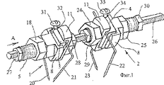
図1を参照すると、肢体の骨用固定装置が示されている。本発明による支持エレメントの分解斜視図が図2に示されている。 Referring to FIG. 1, a limb bone fixation device is shown . Exploded perspective view of a support element according to the invention is shown in Figure 2.
本発明による肢体の骨用固定装置は、少なくとも2つの支持エレメント1及び2を含んでいる。それらの各支持エレメントは、両面に定着円筒体5及び6を有する矩形の角柱として形成された定着受け台3または4を含んでいる。それらの各定着受け台は、調節用の貫通した開口部7を有している(図2)。定着円筒体5上には、ベース9を有する多面体角柱として形成されたクランプ部材8が存在する。このベースは、対向する両側面から切断された円筒体として形成されていて、開放した長手方向の矩形状スロット10を有している。別のクランプ部材11は、対向する両側面から切断された円筒体として形成されていて、開放した長手方向の矩形状スロット12を有している。クランプ部材8と別のクランプ部材11は、それぞれ、貫通した開口部13a及び13を有しており、これらの開口部の軸は、それぞれの切断面14、15及び16、17に平行である。クランプ部材8及び別のクランプ部材11は、それぞれ、定着受け台3及び4の各面を長手方向の開放した矩形状スロット10及び12によりそれぞれ取り囲み、定着円筒体5及び6上に位置付けられている。ある角度を為して位置付けられたワイヤー20及び21のそれぞれの端部は、締付ナット18及び19の助けを借りて、クランプ部材8及び別のクランプ部材11により取り付けられている(図3)。ワイヤー22及び23の端部は、同様に、締付ナット24及び25の助けを借りて支持エレメントに固定されている(図1)。定着受け台3及び4は、それぞれ1対の調整ナット27、28及び29、30を用いて、長手方向の移動を可能にするようにロッド26上に位置付けられている。定着受け台3及び4のそれぞれは、ロックエレメント31及び33を有している。それらの各ロックエレメントは、それぞれ、開口部32及び34内に配置されている。それらの開口部の軸は、上記調節用エレメント(定着受け台)3及び4のそれぞれの調節開口部7の軸に対して垂直である。上記開口部32及び34のそれぞれは、矩形状の角柱として形成された定着受け台3及び4のそれぞれの側縁35に形成されている。
The limb bone fixation device according to the invention comprises at least two
更に、角柱として形成された定着受け台3及び4のそれぞれは、それの側面のうちの一つに形成された開口部36を有している(図4)。この開口部の軸は、定着受け台3及び4のそれぞれの上記長手方向の調節開口部7の軸に対して垂直である。
Further, each of the fixing cradles 3 and 4 formed as prisms has an
ロックエレメント31及び33のそれぞれは、ネジとして形成することができる(図1、2、3、4、5)。各ロックエレメントの先端面37(図3)及び38(図5)は、それの縦軸に対して垂直に形成されている。
Each of the locking
ワイヤー20及び21(図1、2)の部分は、一つの変形態様として、ある角度を為して相互に曲げられていてよい。
The portions of the
更に、ワイヤー39及び40(図4、5)の各取り付け側端部は相互に平行であり、そして、骨に貫入される側の端部は、シンプルで信頼性のある固定を得るべく、相互にある角度を為している。
In addition, the attachment ends of the
適用範囲を高めるための肢体の骨の固定装置は、2つの支持エレメント41及び42を含んでいる(図6)。その第一の支持エレメント41(図7)は、ヘッド44を有するブッシュ43として形成された定着受け台を含んでいる。上記ヘッド44には開口部45が存在する。この開口部の軸は、ブッシュ43の軸に対して垂直である。開口部45にはロックエレメント46が存在する。このロックエレメントはネジとして形成されており、そのネジの先端面は、ロックエレメント46の軸に対して垂直である。ブッシュ43の外面にはネジ切り部が存在し、開放した矩形状スロット48と長手方向に貫通した調節開口部49とを有する角柱として形成された固定エレメント47が存在する。更に、開放したスロット51と長手方向に貫通した開口部52とを有する角柱として形成された別の固定エレメント50と固着エレメント53が存在する。長手方向の平坦なスポットを有する第一の支持エレメントは、2つの調節エレメント55、56を用いて、長手方向の移動を可能にするようにロッド54上に位置付けられている(図6)。ロッド54は、ボルト締めされる接合部57により相互に連結されたブラケット58及び59でできた接続ユニットを用いて、一端部が回動可能に接続される。ブラケット58はロッド54の端部に取り付けられる。ブラケット59は、アーチ60として形成された定着支持体に取り付けられる。アーチの各端部にはブラケット61及び62が存在し、ワイヤー63の両端部が、ワイヤー固定ボルト64及び65とナット66及び67の助けを借りてそれらに取り付けられている。更に、ワイヤー68の両端部は、ブラケット61及び62、ワッシャー69及び70、及びナット71及び72を用いて、反対側にアーチ状支持体60に取り付けられている。ワッシャー69及び70は、そこにワイヤー68の端部を位置付けるためのスロット73及び74を有している。
The limb bone fixation device for increasing the coverage includes two
肢体の骨用固定装置の一つの変形態様として、第一の支持エレメントは、ヘッドを有するブッシュとして形成された定着支持体75を含んでいる(図8)。上記ブッシュの外面と内面にはネジ切りされている。支持体75のヘッドはプレートとして形成されている。クランプ部材76は、ベース77と長手方向に貫通した調節開口部78とを有する角柱として形成されている。別のクランプ部材79は、開放したスロット80と長手方向に貫通した開口部81とを有する角柱として形成され、支持体75上に配置されている。固着エレメント82は、上記定着支持体75に取り付けられる。ワイヤー83及び84の端部は、固着エレメント82を用いて取り付けられている。第二の支持エレメントは、ヘッドを有するブッシュとして形成された定着支持体85を含んでいる。上記ブッシュの内面は滑らかであり、そして、外面にはネジ切りが為されている。クランプ部材86は、ベースと長手方向に貫通した調節開口部とを有している。別のクランプ部材87は、開放したスロットと長手方向に貫通した調節開口部とを有する角柱として形成されている。
As a variant of the limb bone fixation device, the first support element includes an anchoring
ワイヤー88及び89の端部とリンク90は、締付(固着)エレメント91を用いて取り付けられている。
The ends of the wires 88 and 89 and the
支持エレメント75及び85の両者は、ロッド92の助けを借りて接続されている。ロッドの一端部は、支持エレメント75、接続プレート93、及び調節エレメント94を取り付けるためのネジ切り部を有している。支持エレメント85は、ロッド92の滑らかな端部上に取り付けられている。
Both
接続プレート93とリンク90は貫通した開口部を有しており、それらは、これらの開口部と、別のロッド95、及び、2対の調整ナット96、97及び98、99の助けを借りて、長手方向の移動を可能にするように相互に接続されている。
The connecting
回動可能のロッド100が、本発明の一つの変形態様において使用される。このロッドは、2つの支持エレメント102及び103間の中央部分にヒンジ(関節接合部)101を有している。これらの両方の支持エレメントは、支持エレメント85と同様な仕方で形成されている。
ロッド100上の支持エレメント102及び103のそれぞれは、対を為す調整ナット104、105及び106、107を用いて、移動可能に位置付けられている。各支持エレメントのリンク90は、別のロッド108上で長手方向に移動可能及び回動可能に位置付けられている。この別のロッドは、中央部分にヒンジ(関節接合部)109を有している。支持エレメント102のリンク90は、別の対の調整ナット110、111を用いて別のロッド108上に配置されており、支持エレメント103のリンク90は、別の対の調整ナット112、113を用いて別のロッド108上に位置付けられている。
Each
本発明の肢体の骨用固定装置は、以下のようにして使用される。 The bone fixation device for limbs of the present invention is used as follows.
少なくとも2対のワイヤー20、21及び22、23が、想定される骨切り術部位の遠位側及び近位側において、相互にある角度を為して骨に挿入される(図1、2、3)。ワイヤー20、21及び22、23の各対の自由端が、約90度の角度を為して相互に向けて曲げられる。この後に骨切り術が行われる。その後、ワイヤー20、21及び22、23の各対の曲げられた端部が、定着受け台3、4の角柱の両側面に位置付けられ、そして、クランプ部材8、別のクランプ部材11、及び、対を為す締付ナット18、19及び24、25を用いて取り付けられる。定着受け台3、4が、対を為すナット27、28及び29、30と、開口部32、34に配置されるロックエレメント31、33を用いて、ロッド26上に取り付けられる。ロッド26の外面のメートルネジがネジ切りされている。ロッド26上の対を為すナット27、28及び29、30を異なる側へ移動させることにより、骨フラグメントの伸延が行われる。ロック用ネジ31、33の先端面37または38とロッド26上の平坦なスポットとの相互作用を犠牲にして、移動を妨げないように、且つ、一方または他方のロックエレメント31または33の回転を防止するように、移動される支持エレメント3及び4のロック用ネジ31または33が移動される。
At least two pairs of
1対のワイヤー39、40を固定するための一つの可能な変形態様(図4、5)は、それらの端部の二回曲げである。クランプ部材8と別のクランプ部材11により固定されるそれらの端部は平行である。これは、骨フラグメントの圧縮または伸延中に加わる力を再分配することを可能にする。
One possible variant for securing a pair of
中手骨を伸ばすときには、2本の真っ直ぐなワイヤー68及び63が中手骨の近位側フラグメントを固定する。それらのワイヤーが、支持エレメント42のアーチ60の端部に取り付けられる(図6)。支持エレメント41が、伸ばされた中手骨の遠位側フラグメントを固定するために使用される。ワイヤーは、固定エレメント47、50間のブッシュ43のヘッド44から一方の側に位置付けられる(図7)。ヘッド44は、四面体角柱として形成されている。これは、固着エレメント53を用いてワイヤーを取り付けるときに、レンチで支持エレメント41を保持することを可能にする。更に、ロックエレメント46が、ヘッド44の側面に形成された開口部45に位置付けられる。これは、支持エレメント41がロッド54に対して相対的に回転するのを防止する。支持エレメント41及び42の相互接続が、ブラケット58、59とボルト締めされる接合部57を用いてヒンジされることにより達成される。ナット55のネジをゆるめ、且つ、ナット56のネジを締めることによる、ネジ切りされているロッド54上における支持エレメント41の移動の助けを借りて、伸延が行われる。
When extending the metacarpal bone, two
小さな骨の短いフラグメントを伸ばすときには、本発明の固定装置に伸延用の2つの支持エレメントが取り付けられる。そのうちの1つの支持エレメントは支持体75を含む(図8)。ワイヤー83及び84の端部が、クランプ部材76及び79を用いて、この支持体に取り付けられる。開放したスロット80が、支持エレメント75のヘッドを取り囲む。クランプ部材76のベースが、クランプ部材79を取り囲む。上記クランプ部材76、79とワイヤー83及び84の端部が、固着エレメント82により取り付けられる。ロッド92のネジ切りされた端部が、支持体75のネジ切りされた開口部にネジ入れされる。接続プレート93が、同じ端部に位置付けられ、調節エレメント94を用いて固定される。定着支持体85がロッド92の滑らかな端部上に位置付けられる。ワイヤー88及び89の端部が、リンク90及び固着エレメント91を用いて、支持体85に取り付けられる。接続プレート93とリンク90が、貫通した開口部の助けを借りて、別のロッド95と2対の調整ナット96、97及び98、99により相互に接続される。別のロッド95上における調整ナット99のネジをゆるめ、且つ、調整ナット98のネジを締めることによる調整ナット98、99の助けを借りた定着支持体85の移動を利用することにより、短い骨フラグメントを伸ばすための伸延が行われる。定着支持体85が、ロッド92の滑らかな部分上を移動させられる。
When extending a short fragment of small bone, two distraction support elements are attached to the fixation device of the present invention . One of the support elements includes a support 75 (FIG. 8). The ends of the
支持エレメント102、103を接続する関節接合部109、101を備えたロッド100、108を有する肢体の骨用固定装置(図9)の一つの変形態様が、短い骨の変形を創出するため、あるいは、関節の病理学を管理するために使用される。1対の調整ナット110、111及び112、113、並びに、1対の調整ナット104、105及び106、107を移動させることにより、骨フラグメントまたは指骨に必要な角度的位置を与える。必要な場合には、対を為す調整ナット104、105及び106、107を用いて、骨フラグメントの長手方向の移動が行われる。
One variant of a limb bone fixation device (FIG. 9) having
本発明の肢体の骨用固定装置は、肢体の骨を伸ばすため、あるいは、指骨または中手骨及び中足骨の骨折を管理するために使用することができる。本発明の固定装置は、隣接した関節の拘縮の排除を可能にし、肢体の早期の充分に価値のあるリハビリテーションを可能にする。更に、本発明の固定装置は、指節関節及び中手指節関節の関節固定に効果的に使用することができる。本発明の固定装置の構造は、指の断端を伸ばすため、1、5中手骨の手の発育異常に対してだけでなく、同時に2、3、4中手骨の手の発育異常に対しても本発明の固定装置の使用を可能にする。必要な数の支持エレメントの組み立ては、隣接した近位側の短い骨を伸ばすときに、指節骨断端のフラグメントの固定を可能にする。ヒンジ接合部は、指節骨の伸ばしを可能にするだけでなく、隣接した関節の拘縮の同時的な予防も可能にする。本発明の固定装置の適用は、患者のセルフサービスの可能性を制限せず、機能的な回復を得るための手の理学的運動療法を可能にする。 Bone fixed device limb of the present invention, since stretch limb bone, or can be used to manage the fractured finger bone or metacarpal and metatarsal bones. The fixation device of the present invention allows for the elimination of adjacent joint contractures and allows for early and fully valuable rehabilitation of the limb. Further, the fixing device of the present invention can be effectively used in arthrodesis of interphalangeal joints and metacarpophalangeal joints. Since the structure of the fixing device of the present invention extends the stump of the finger, not only against abnormal growth of the hand of the 1,5 metacarpal hand, but also abnormal growth of the hand of the 2, 3,4 metacarpal hand In contrast, the fixing device of the present invention can be used. The assembly of the required number of support elements allows for fixation of the phalangeal stump fragments when stretching adjacent proximal short bones. The hinge joint not only allows for the extension of the phalanx, but also allows for the simultaneous prevention of contracture of adjacent joints. The application of the fixation device of the present invention does not limit the patient's potential for self-service and allows physical exercise therapy of the hand to obtain functional recovery.
1、2 支持エレメント
3、4 定着受け台
5、6 定着円筒体
7 調節用の貫通した開口部
8 クランプ部材
9 ベース
10 矩形状スロット
11 別のクランプ部材
12 長手方向の矩形状スロット
13、13a 貫通した開口部
14、15 クランプ部材の切断面
16、17 別のクランプ部材の切断面
18、19 締付ナット
20、21、22,23 ピン
24、25 締付ナット
26 ロッド
27、28 1対の調整ナット
29、30 1対の調整ナット
31、33 ロックエレメント
32、34 開口部
35 側縁
36 開口部
37、38 先端面
39、40 ワイヤー端
41、42 支持エレメント
43 ブッシュ
44 ブッシュのヘッド
45 開口部
46 ロックエレメント
47 固定エレメント
48 矩形状スロット
49 調節開口部
50 固定エレメント
51 開放したスロット
52 長手方向に貫通した開口部
53 固着エレメント
54 ロッド
55、56 調節エレメント
57 ボルト締めされた接合部
58、59 ブラケット
60 アーチ状支持体
61、62 ブラケット
63 ワイヤー
64、65 ワイヤー固定ボルト
66、67 ナット
68 ワイヤー
69、70 ワッシャー
71、72 ナット
73、74 スロット
75 支持体
76 クランプ部材
77 ベース
78 調節開口部
79 クランプ部材
80 開放したスロット
81 長手方向に貫通した開口部
82 固着エレメント
83、84 ワイヤー
85 定着支持体
86 クランプ部材
87 別のクランプ部材
88、89 ワイヤー
90 リンク
91 締付エレメント
92 ロッド
93 接続プレート
94 調節エレメント
95 別のロッド
96、97、98、99 2対の調整ナット
100 ロッド
101 関節接合部
102、103 支持エレメント
104、105、106、107 調整ナット
108 別のロッド
109 関節接合部
110、111、112、113 別の調整ナット
DESCRIPTION OF SYMBOLS 1 , 2 Support element 3 , 4 Fixing stand 5 , 6 Fixing cylindrical body 7 Through-opening part 8 for adjustment Clamp member 9 Base 10 Rectangular slot 11 Another clamp member 12 Longitudinal rectangular slot 13 , 13a penetration Openings 14, 15 Clamping member cutting surfaces 16, 17 Clamping member cutting surfaces 18, 19 Clamping nuts 20 , 21 , 22, 23 Pins 24, 25 Clamping nut 26 Rods 27, 28 One pair of adjustments Nuts 29, 30 A pair of adjusting nuts 31, 33 Lock elements 32, 34 Opening 35 Side edge 36 Opening 37 , 38 Tip surface 39, 40 Wire end 41, 42 Support element 43 Bush 44 Bush head 45 Opening 46 Lock element 47 Fixed element 48 Rectangular slot 49 Adjustment opening 50 Fixed element 51 Opened Slot 52 Opening 53 penetrating in the longitudinal direction Sticking element 54 Rod 55, 56 Adjustment element 57 Bolted joint 58, 59 Bracket 60 Arched support 61, 62 Bracket 63 Wire 64, 65 Wire fixing bolt 66, 67 Nut 68 Wire 69, 70 Washer 71, 72 Nut 73, 74 Slot 75 Support 76 Clamp member 77 Base 78 Adjusting opening 79 Clamping member 80 Opening slot 81 Opening 82 extending in the longitudinal direction Fixing element 83, 84 Wire 85 fixing the support 86 clamping member 87 by clamping members 88, 89 wire 90 links 91 adjusting nut 100 of element 92 rods 93 connecting plate 94 regulatory elements 95 by the rods 96, 97, 98 and 99 two pairs of tightening Head 101 articulations 102 and 103 support elements 104, 105, 106, 107 adjustment nut 108 by the rod 109 articulated joint 110, 111, 112 and 113 by the adjusting nut
Claims (6)
上記支持エレメントは、
両面に定着円筒体が配置され、長手方向に貫通した調節開口部を有する矩形状の角柱として形成された定着受け台と、
ベース及び長手方向に貫通した開口部を有する多面体の角柱として形成されたクランプ部材と、
対向する両側面が切断された円筒体として形成され、開放した矩形状スロットを有する別のクランプ部材と、
2つの締付ナットと、
2つの調整ナットを用いて移動可能に上記支持エレメントが取り付けられるロッドと、
ワイヤーとを具備し、
上記ベースは、対向する両側面が切断された円筒体として形成され、開放した長手方向の矩形状スロットを有し、上記別のクランプ部材は軸が切断面に平行である調整開口部を有し、そして、上記ワイヤーは、幾つかの端部が骨を貫通し、他の端部が支持エレメントに取り付けられる肢体の骨用固定装置。Consisting of at least two support elements,
The support element is
A fixing cradle formed as a rectangular prism having a fixing cylindrical body disposed on both sides and having an adjustment opening penetrating in the longitudinal direction;
A clamping member formed as a polygonal prism having a base and an opening penetrating in the longitudinal direction;
Another clamping member formed as a cylindrical body having opposite side faces cut and having an open rectangular slot;
Two clamping nuts,
A rod to which the support element is movably attached using two adjustment nuts;
Wire and
The base is formed as a cylindrical body having opposite side surfaces cut and has an open longitudinal rectangular slot, and the other clamping member has an adjustment opening whose axis is parallel to the cutting surface. And the said wire is a bone fixing device for the limbs in which some ends penetrate the bone and the other ends are attached to the support element.
該開口部の軸は、前記長手方向に貫通した調節開口部の軸に対して垂直であり、
ロックエレメントを有する請求項1に記載の固定装置。Each fixing cradle has an opening formed in one of the side ribs;
The axis of the opening is perpendicular to the axis of the adjustment opening penetrating in the longitudinal direction;
The fixing device according to claim 1, further comprising a locking element.
Applications Claiming Priority (1)
| Application Number | Priority Date | Filing Date | Title |
|---|---|---|---|
| PCT/RU2001/000084 WO2002067790A1 (en) | 2001-02-26 | 2001-02-26 | Fixator for hand and foot bones |
Publications (3)
| Publication Number | Publication Date |
|---|---|
| JP2004522536A JP2004522536A (en) | 2004-07-29 |
| JP2004522536A5 JP2004522536A5 (en) | 2005-12-22 |
| JP4352112B2 true JP4352112B2 (en) | 2009-10-28 |
Family
ID=20129605
Family Applications (1)
| Application Number | Title | Priority Date | Filing Date |
|---|---|---|---|
| JP2002567165A Expired - Fee Related JP4352112B2 (en) | 2001-02-26 | 2001-02-26 | Limb bone fixation device |
Country Status (5)
| Country | Link |
|---|---|
| EP (1) | EP1374787B1 (en) |
| JP (1) | JP4352112B2 (en) |
| AT (1) | ATE365506T1 (en) |
| DE (1) | DE60129169T2 (en) |
| WO (1) | WO2002067790A1 (en) |
Families Citing this family (4)
| Publication number | Priority date | Publication date | Assignee | Title |
|---|---|---|---|---|
| US8758343B2 (en) | 2005-04-27 | 2014-06-24 | DePuy Synthes Products, LLC | Bone fixation apparatus |
| FR2959926A1 (en) * | 2010-05-11 | 2011-11-18 | Xavier Renard | System for exerting opposite forces respectively at points of e.g. hand bone separated by fracture, has screw with net unwound on surface of rod along pitch value such that pin is partially plugged between two net portions |
| KR101501635B1 (en) * | 2014-09-30 | 2015-03-12 | 고려대학교 산학협력단 | Variable external fixation device |
| CN104758015B (en) * | 2015-04-21 | 2017-03-22 | 张家港市亚堤仕医疗咨询管理有限公司 | Skin drafting device |
Family Cites Families (8)
| Publication number | Priority date | Publication date | Assignee | Title |
|---|---|---|---|---|
| SU1715333A1 (en) * | 1986-04-11 | 1992-02-28 | Курганский Научно-Исследовательский Институт Экспериментальной И Клинической Ортопедии И Травматологии | Compression-distraction device |
| SU1708322A1 (en) * | 1987-04-13 | 1992-01-30 | Курганский Научно-Исследовательский Институт Экспериментальной И Клинической Ортопедии И Травматологии | Compression-distraction apparatus |
| JPH03501092A (en) * | 1988-05-26 | 1991-03-14 | フセソユズニ クルガンスキ ナウチニ ツェントル “ボススタノビテルナヤ トラフマトロギア イ オルトペディア” | Osteosynthesis compression-distraction device |
| CH690293A5 (en) * | 1994-09-06 | 2000-07-14 | Jaquet Orthopedie | Joint for components of an external fixator. |
| RU2186U1 (en) * | 1994-10-28 | 1996-06-16 | Российский научный центр "Восстановительная травматология и ортопедия" им. акад.Г.А.Илизарова | MINI FIXER FOR REMOVAL OF FINGERS OF THE FINGERS OF THE BRUSH |
| US5961515A (en) * | 1995-03-01 | 1999-10-05 | Smith & Nephew, Inc. | External skeletal fixation system |
| NL1007426C1 (en) * | 1997-11-03 | 1999-05-04 | Gerrit Johannes Termaten | Device for mutually fixing bone parts. |
| US5921985A (en) * | 1998-02-10 | 1999-07-13 | Texas Scottish Rite Hospital | External fixation device and method |
-
2001
- 2001-02-26 WO PCT/RU2001/000084 patent/WO2002067790A1/en active IP Right Grant
- 2001-02-26 JP JP2002567165A patent/JP4352112B2/en not_active Expired - Fee Related
- 2001-02-26 EP EP01943980A patent/EP1374787B1/en not_active Expired - Lifetime
- 2001-02-26 DE DE60129169T patent/DE60129169T2/en not_active Expired - Lifetime
- 2001-02-26 AT AT01943980T patent/ATE365506T1/en not_active IP Right Cessation
Also Published As
| Publication number | Publication date |
|---|---|
| DE60129169T2 (en) | 2008-03-06 |
| WO2002067790A1 (en) | 2002-09-06 |
| EP1374787B1 (en) | 2007-06-27 |
| EP1374787A4 (en) | 2005-02-09 |
| JP2004522536A (en) | 2004-07-29 |
| EP1374787A1 (en) | 2004-01-02 |
| ATE365506T1 (en) | 2007-07-15 |
| DE60129169D1 (en) | 2007-08-09 |
Similar Documents
| Publication | Publication Date | Title |
|---|---|---|
| US5885282A (en) | Apparatus for treatment of fracture and malunion of the distal radius | |
| KR100477282B1 (en) | Spatial frame | |
| JP6103773B2 (en) | Orthopedic external fixator for elbow joint | |
| US4895141A (en) | Unilateral external fixation device | |
| US6793655B2 (en) | External fixator for distal radius fractures | |
| US6162222A (en) | Method and apparatus for external fixation of the pelvis | |
| US6162223A (en) | Dynamic wrist fixation apparatus for early joint motion in distal radius fractures | |
| US9265529B2 (en) | Orthopedic fixation systems and methods | |
| US6010501A (en) | Method and apparatus for external fixation of small bones | |
| US20120150186A1 (en) | External fixation apparatus with angularly adjustable drill guiding and pin clamping means | |
| JPH1057397A (en) | Outer fixture | |
| JP2005527314A (en) | Bone fixator with outrigger | |
| US9066757B2 (en) | Orthopedic external fixator and method of use | |
| US10993868B2 (en) | Dynamic foot plate | |
| WO2004045451A2 (en) | Apparatus and method for maintaining bones in a healing position | |
| JP4352112B2 (en) | Limb bone fixation device | |
| EP2967958B1 (en) | Dynamic footplate | |
| JP2004522536A5 (en) | ||
| US10463522B2 (en) | Dynamic foot plate | |
| KR101501635B1 (en) | Variable external fixation device | |
| RU2314766C2 (en) | Locator for wrist and for bones | |
| RU2363414C1 (en) | Articulated device for repositioning and fixing fractures of long bones | |
| WO2013005130A1 (en) | Fixator for bone fractures | |
| US20240065739A1 (en) | Rescue external fixation system | |
| RU2749897C1 (en) | Apparatus for treatment of combined fractures of pelvic and femoral bones |
Legal Events
| Date | Code | Title | Description |
|---|---|---|---|
| A521 | Request for written amendment filed |
Free format text: JAPANESE INTERMEDIATE CODE: A523 Effective date: 20050214 |
|
| A621 | Written request for application examination |
Free format text: JAPANESE INTERMEDIATE CODE: A621 Effective date: 20050214 |
|
| A521 | Request for written amendment filed |
Free format text: JAPANESE INTERMEDIATE CODE: A821 Effective date: 20070518 |
|
| RD02 | Notification of acceptance of power of attorney |
Free format text: JAPANESE INTERMEDIATE CODE: A7422 Effective date: 20070518 |
|
| RD02 | Notification of acceptance of power of attorney |
Free format text: JAPANESE INTERMEDIATE CODE: A7422 Effective date: 20070528 |
|
| A521 | Request for written amendment filed |
Free format text: JAPANESE INTERMEDIATE CODE: A821 Effective date: 20070530 |
|
| A072 | Dismissal of procedure [no reply to invitation to correct request for examination] |
Free format text: JAPANESE INTERMEDIATE CODE: A072 Effective date: 20071016 Free format text: JAPANESE INTERMEDIATE CODE: A073 Effective date: 20071016 |
|
| A521 | Request for written amendment filed |
Free format text: JAPANESE INTERMEDIATE CODE: A523 Effective date: 20071119 |
|
| A521 | Request for written amendment filed |
Free format text: JAPANESE INTERMEDIATE CODE: A821 Effective date: 20080228 |
|
| RD02 | Notification of acceptance of power of attorney |
Free format text: JAPANESE INTERMEDIATE CODE: A7422 Effective date: 20080228 |
|
| A521 | Request for written amendment filed |
Free format text: JAPANESE INTERMEDIATE CODE: A821 Effective date: 20080228 |
|
| A131 | Notification of reasons for refusal |
Free format text: JAPANESE INTERMEDIATE CODE: A131 Effective date: 20080415 |
|
| A601 | Written request for extension of time |
Free format text: JAPANESE INTERMEDIATE CODE: A601 Effective date: 20080715 |
|
| A602 | Written permission of extension of time |
Free format text: JAPANESE INTERMEDIATE CODE: A602 Effective date: 20080723 |
|
| A02 | Decision of refusal |
Free format text: JAPANESE INTERMEDIATE CODE: A02 Effective date: 20081224 |
|
| A521 | Request for written amendment filed |
Free format text: JAPANESE INTERMEDIATE CODE: A523 Effective date: 20090324 |
|
| A911 | Transfer to examiner for re-examination before appeal (zenchi) |
Free format text: JAPANESE INTERMEDIATE CODE: A911 Effective date: 20090513 |
|
| TRDD | Decision of grant or rejection written | ||
| A01 | Written decision to grant a patent or to grant a registration (utility model) |
Free format text: JAPANESE INTERMEDIATE CODE: A01 Effective date: 20090602 |
|
| A01 | Written decision to grant a patent or to grant a registration (utility model) |
Free format text: JAPANESE INTERMEDIATE CODE: A01 |
|
| A61 | First payment of annual fees (during grant procedure) |
Free format text: JAPANESE INTERMEDIATE CODE: A61 Effective date: 20090625 |
|
| R150 | Certificate of patent or registration of utility model |
Free format text: JAPANESE INTERMEDIATE CODE: R150 |
|
| FPAY | Renewal fee payment (event date is renewal date of database) |
Free format text: PAYMENT UNTIL: 20120807 Year of fee payment: 3 |
|
| LAPS | Cancellation because of no payment of annual fees |