JP4351114B2 - Steel cord and pneumatic radial tire - Google Patents
Steel cord and pneumatic radial tire Download PDFInfo
- Publication number
- JP4351114B2 JP4351114B2 JP2004158330A JP2004158330A JP4351114B2 JP 4351114 B2 JP4351114 B2 JP 4351114B2 JP 2004158330 A JP2004158330 A JP 2004158330A JP 2004158330 A JP2004158330 A JP 2004158330A JP 4351114 B2 JP4351114 B2 JP 4351114B2
- Authority
- JP
- Japan
- Prior art keywords
- filament
- core
- steel
- sheath
- cord
- Prior art date
- Legal status (The legal status is an assumption and is not a legal conclusion. Google has not performed a legal analysis and makes no representation as to the accuracy of the status listed.)
- Expired - Fee Related
Links
Images


Classifications
-
- D—TEXTILES; PAPER
- D07—ROPES; CABLES OTHER THAN ELECTRIC
- D07B—ROPES OR CABLES IN GENERAL
- D07B1/00—Constructional features of ropes or cables
- D07B1/06—Ropes or cables built-up from metal wires, e.g. of section wires around a hemp core
- D07B1/0606—Reinforcing cords for rubber or plastic articles
- D07B1/062—Reinforcing cords for rubber or plastic articles the reinforcing cords being characterised by the strand configuration
- D07B1/0633—Reinforcing cords for rubber or plastic articles the reinforcing cords being characterised by the strand configuration having a multiple-layer configuration
-
- D—TEXTILES; PAPER
- D07—ROPES; CABLES OTHER THAN ELECTRIC
- D07B—ROPES OR CABLES IN GENERAL
- D07B2201/00—Ropes or cables
- D07B2201/20—Rope or cable components
- D07B2201/2015—Strands
- D07B2201/2024—Strands twisted
- D07B2201/2027—Compact winding
- D07B2201/2028—Compact winding having the same lay direction and lay pitch
-
- D—TEXTILES; PAPER
- D07—ROPES; CABLES OTHER THAN ELECTRIC
- D07B—ROPES OR CABLES IN GENERAL
- D07B2201/00—Ropes or cables
- D07B2201/20—Rope or cable components
- D07B2201/2047—Cores
- D07B2201/2052—Cores characterised by their structure
- D07B2201/2059—Cores characterised by their structure comprising wires
-
- D—TEXTILES; PAPER
- D07—ROPES; CABLES OTHER THAN ELECTRIC
- D07B—ROPES OR CABLES IN GENERAL
- D07B2201/00—Ropes or cables
- D07B2201/20—Rope or cable components
- D07B2201/2047—Cores
- D07B2201/2066—Cores characterised by the materials used
-
- D—TEXTILES; PAPER
- D07—ROPES; CABLES OTHER THAN ELECTRIC
- D07B—ROPES OR CABLES IN GENERAL
- D07B2201/00—Ropes or cables
- D07B2201/20—Rope or cable components
- D07B2201/2047—Cores
- D07B2201/2067—Cores characterised by the elongation or tension behaviour
- D07B2201/2068—Cores characterised by the elongation or tension behaviour having a load bearing function
Landscapes
- Ropes Or Cables (AREA)
- Tires In General (AREA)
Description
本発明は、スチールコード及び空気入りラジアルタイヤに関し、主としてラジアルタイヤのカーカスやベルトの補強材として用いられるコード生産性が良く、かつ耐疲労性に優れるスチールコード、及びそのスチールコードを用いた耐久性を向上した空気入りラジアルタイヤに関する。 The present invention relates to a steel cord and a pneumatic radial tire, and a steel cord that is mainly used as a reinforcing material for a carcass or belt of a radial tire and has excellent fatigue resistance, and durability using the steel cord The present invention relates to a pneumatic radial tire with improved performance.
トラック・バス用やライトトラック用などの大型空気入りラジアルタイヤのカーカスの補強材としては、従来より2層撚りや3層撚りなどの多層構造のスチールコードが広く使用され、中でも使用条件が過酷なタイヤには図4に示す3+9+15×0.175+1構造のようなフィラメント径が細く、フィラメント構成の多い3層構造のスチールコード50が使用されている。
As a carcass reinforcement material for large pneumatic radial tires for trucks, buses and light trucks, steel cords with a multi-layer structure such as two-layer twist and three-layer twist have been widely used in the past. The tire uses a
一般に、3層構造のスチールコードは、コアと内外シース、ラッピングワイヤの撚り方向がS/S/Z/S方向に撚られてコードの回転バランスを良好にしている。しかし、このようなスチールコードでは、フィラメント同士及びラッピングワイヤとシースとの接触によるフレッチング摩耗によってフィラメント断面積が減少して除々にコード強力の低下を起こすとともに、めっきが削られて耐腐食疲労性を低下させ、フレッチング摩耗が進行するとタイヤ使用中の衝撃や圧縮歪みによりコード破断を生じるという問題がある。また、その撚り構造からコード製造時の撚り線工程が多くなり生産性が悪くコードコストを上昇させている。 In general, in a steel cord having a three-layer structure, the twisting direction of the core, the inner and outer sheaths, and the wrapping wire is twisted in the S / S / Z / S direction to improve the cord rotation balance. However, in such a steel cord, the cross-sectional area of the filament decreases due to fretting wear due to contact between the filaments and the wrapping wire and the sheath, and the cord strength gradually decreases, and the plating is scraped to reduce corrosion fatigue resistance. When fretting wear is reduced and the fretting wear proceeds, there is a problem that cord breakage occurs due to impact or compression strain during use of the tire. Moreover, the twisted wire process at the time of manufacture of a cord increases due to the twisted structure, resulting in poor productivity and an increase in cord cost.
このフレッチングによる耐疲労性の低下やコストの問題を改善するものとして、1本のスチールフィラメントからなるコアのまわりに2層以上の同軸層(シース)を配し、この同軸層を同一方向、同一ピッチで撚り合わせて各フィラメント間の線接触化を図るコンパクト撚り構造のスチールコード、例えば1×19構造のスチールコード、また、1本のコアと、コアのまわりに配列した6本のフィラメントからなる内層シースと、内層シースの外接円上に配置され得るだけの数より1本ないし2本少ないフィラメント数を外層シースに有し、内層シースと外層シースを同一方向、異ピッチで撚り合わせ、さらにラップフィラメントが略された3層構造のスチールコードが開示され、フレッチング摩耗の低減とコードの拘束性を維持し、さらにコアフィラメントを太くしてシースフィラメント間の接触圧を下げ耐疲労性を向上することが行われている(特許文献1,2)。
上記文献に記載の1×19、1+6+11構造などの従来のスチールコードは、コードの中心基本構造となるコアフィラメントとシースフィラメントとが略同等の抗張力を持つフィラメントからなり、かつ撚り線時にコアフィラメントに撚りが入らずストレートな状態でコードに形成されている。 Conventional steel cords such as the 1 × 19, 1 + 6 + 11 structure described in the above document are composed of filaments having core filaments and sheath filaments that have substantially the same tensile strength as the core basic structure of the cords. The cord is formed in a straight state without twisting.
このようなスチールコードをラジアルタイヤのカーカスに使用した場合、タイヤが長距離連続走行や重荷重条件下で使用される車両に装着し用いられると、タイヤにかかる繰り返し応力により、特にサイド部からショルダー部におけるカーカスに歪が集中し、ストレートなコアフィラメントが金属疲労により他のシースフィラメントに先行して破壊を生じやすくなり、破断したコアフィラメントがタイヤサイド部から突出し空気漏れを生じたり、コード内の他のフィラメントの疲労破壊を促進してコードの破断を発生しタイヤ故障の原因になるという問題がある。 When such a steel cord is used for a carcass of a radial tire, when the tire is mounted and used on a vehicle that is used for long-distance continuous running or heavy load conditions, the shoulder is particularly stressed from the side due to the repeated stress applied to the tire. Strain concentrates on the carcass at the section, and the straight core filament is likely to break before other sheath filaments due to metal fatigue, and the broken core filament protrudes from the tire side section and causes air leakage, There is a problem that fatigue breakage of other filaments is promoted to cause cord breakage and cause tire failure.
本発明は、上記問題に鑑み、1×19構造のようなストレートなコアフィラメントを有し、同一方向、同一ピッチで撚り合わされたシースからなる耐フレッチング性を改善したスチールコードにおいて、コアフィラメントの耐疲労性を改善することでコアの金属疲労による先行破壊を回避した耐久性に優れるスチールコード、及びそのスチールコードを用いた空気入りラジアルタイヤを提供することを目的とするものである。 In view of the above problems, the present invention provides a steel cord having a straight core filament such as a 1 × 19 structure and having improved resistance to fretting made of a sheath twisted in the same direction and at the same pitch. An object of the present invention is to provide a steel cord excellent in durability by avoiding the preceding failure due to metal fatigue of the core by improving the fatigue property, and a pneumatic radial tire using the steel cord.
本発明者らは、1×19構造のようなストレートな1本のコアフィラメントを有するスチールコードにおいて、コアフィラメントの耐疲労性の向上に関して鋭意研究をしたところ、コアとシースの構成フィラメントの抗張力の関係と、コアフィラメントの抗張力とその結節強力保持率の関係に着目してその最適値を見出し本発明の完成に到った。 In the steel cord having a single straight core filament such as a 1 × 19 structure, the present inventors have conducted intensive research on improving the fatigue resistance of the core filament. Focusing on the relationship, the relationship between the tensile strength of the core filament and the knot strength retention, the optimum value was found and the present invention was completed.
すなわち、本発明は、1本のスチールフィラメントからなるコアと、前記コアの周りに配列された複数本のスチールフィラメントからなる少なくとも2層のシースとを有し、前記コアを構成する1本のスチールフィラメントがストレートなフィラメントであり、前記シースを構成するスチールフィラメントが同一方向、同一ピッチで撚り合わされているスチールコードであって、前記コアフィラメントが、前記シースフィラメントよりも5%以上高い抗張力を有し、かつ結節強力保持率が60%以上であり、前記コアフィラメントの径(dc)と前記シースフィラメントの径(ds)との比が、1≦dc/ds≦1.15の関係を満たすことを特徴とするスチールコードである。 That is, the present invention has a core composed of one steel filament and a sheath of at least two layers composed of a plurality of steel filaments arranged around the core, and constitutes the core. The filament is a straight filament, and the steel filament constituting the sheath is a steel cord twisted in the same direction and the same pitch, and the core filament has a tensile strength higher by 5% or more than the sheath filament. and knot strength retention of Ri der 60%, the ratio of the diameter of the core filament (dc) and the sheath filament diameter (ds) is, to satisfy the relationship of 1 ≦ dc / ds ≦ 1.15 It is a steel cord characterized by
本発明のスチールコードは、シースを構成するスチールフィラメントが同一方向、同一ピッチで撚り合わされていることでフィラメント相互間の線接触化によりフレッチング摩耗を均一化すると共に摩耗量を従来コードよりも大幅に軽減してコード強力を保持することができる。 In the steel cord of the present invention, the steel filaments constituting the sheath are twisted in the same direction and the same pitch, so that the fretting wear is made uniform by making line contact between the filaments, and the wear amount is significantly larger than that of the conventional cord. It can be reduced and code strength can be maintained.
そして、コアフィラメントの抗張力を他のシースフィラメントの抗張力よりも5%以上高くすることで、抗張力の増加と共に疲労限が向上しストレートなコアフィラメントの耐疲労性が改善され、さらに、コアフィラメントの結節強力保持率を60%以上に確保することで、抗張力の増加に伴う鋼の脆化に基づく靭性の低下を抑制し、疲労限の向上と耐疲労性低下の抑制とを両立させる最適値を得ることでコアフィラメントの金属疲労による先行破壊を防ぐことができる。 By increasing the tensile strength of the core filament by 5% or more than the tensile strength of the other sheath filaments, the fatigue limit is improved as the tensile strength is increased, and the fatigue resistance of the straight core filament is improved. By securing a high strength retention rate of 60% or more, a decrease in toughness due to embrittlement of steel accompanying an increase in tensile strength is suppressed, and an optimum value that achieves both an improvement in fatigue limit and a decrease in fatigue resistance is obtained. Therefore, it is possible to prevent the preceding failure due to metal fatigue of the core filament.
また、前記コアフィラメントの径(dc)と前記シースフィラメントの径(ds)との比が、1≦dc/ds≦1.15の関係を満たし、特にコアフィラメントをシースフィラメントよりやや太くすることにより、シースフィラメント間の接触圧を下げて耐疲労性をより向上することができる。しかし、コアとシースのフィラメント径差を大きくしすぎると、シースフィラメントが動きやすくなり耐フレッチング性や耐疲労性を低下させるので、dc/dsの上限は1.15程度である。 Further, the ratio of the diameter of the core filament (dc) and the sheath filament diameter (ds) is, meets the
そして、本発明の空気入りラジアルタイヤは、上記スチールコードを補強材として用いたことを特徴とし、特にカーカスに用いることでフレッチング摩耗とコアの耐疲労性を改善しカーカス耐久性に優れた長寿命化が図られる空気入りラジアルタイヤとすることができる。 The pneumatic radial tire of the present invention is characterized in that the steel cord is used as a reinforcing material, and in particular, by using it in a carcass, the fretting wear and the fatigue resistance of the core are improved, and the carcass durability has a long life. A pneumatic radial tire can be obtained.
本発明のスチールコードによれば、フィラメント相互間のフレッチング摩耗を軽減してコード強力を保持し、コアフィラメントの耐疲労性を改善することでコアフィラメントの金属疲労による先行破壊を防止してスチールコードの耐久性を向上することができ、このスチールコードを用いた空気入りラジアルタイヤの使用寿命を大幅に延ばすことが可能となる。 According to the steel cord of the present invention, the fretting wear between filaments is reduced, the strength of the cord is maintained, the fatigue resistance of the core filament is improved, and the preceding failure due to the metal fatigue of the core filament is prevented to prevent the steel cord. As a result, the service life of the pneumatic radial tire using the steel cord can be greatly extended.
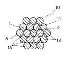
図1は本発明の一実施形態を示す1×19×0.20構造のスチールコード1の断面図である。スチールコード10は、コード10の中心基本構造であるコア1を構成する1本のコアフィラメント11と、コアフィラメント11の周りに配列されたインナーシース2を構成する6本のフィラメント12と、インナーシース2の周りに配列されたアウターシース3を構成する12本のフィラメント13とで構成され、全てのフィラメント11,12,13は0.20mmの同径である。
FIG. 1 is a cross-sectional view of a
スチールコード1は、コアフィラメント11とその周囲に配されたインナー及びアウターシース2,3のフィラメント12,13とが全て同一方向、同一のピッチで撚り合わされ、図に示すようにコード断面輪郭が略六角形状をなして、コアフィラメント11はコード10の中心にストレートな状態で位置して形成されている。
In the
このスチールコード10は、通常のチューブラー型撚り線機やバンチャー型撚り線機を使用して、19本のフィラメントを同時に撚り線機に供給し1回の撚り線加工によって製造できるので、コードの製造工程数減によるコードコストの低減が可能になる。
This
上記スチールコード1を構成するコアフィラメント径(dc)及びシースフィラメント径(ds)は、それぞれ0.15〜0.40mmの範囲であり、0.15mmより細いフィラメントは生産性が悪くタイヤ用スチールコードとしてコスト的に見合わず、0.40mmを越えると剛直になって撚り線加工性を低下させ、またタイヤ特性や耐疲労性にも悪影響する。カーカス用コードとして用いられる場合は、0.175〜0.23mmにあるものが耐疲労性や可撓性を確保する観点で好ましい。
The core filament diameter (dc) and the sheath filament diameter (ds) constituting the
このスチールフィラメント11,12,13は、炭素含有量が0.70〜0.92重量%程度にある高炭素鋼(例えば、JIS G3502規定のピアノ線材)からなり、2500〜3500N/mm2 程度の抗張力を有し、さらに軽量化の観点から抗張力は2700N/mm2 以上が好ましく、さらに2900N/mm2 以上にある高抗張力であることがより好ましい。しかし、抗張力が3500N/mm2 を越えると伸線加工性の悪化や脆性の低下により耐疲労性が低下していく。
The
また、フィラメント11,12,13は、ゴムとの接着を確保するために銅比率が62〜68%のブラスめっきで被覆されていることが好ましい。
Moreover, it is preferable that the
本発明のスチールコード10においては、コアフィラメント11が、スチールコード10を構成する他のシースフィラメント12,13よりも5%以上高い抗張力を有するものである。
In the
このコアフィラメント11の抗張力を高くすることで、抗張力の増加とともに疲労限が向上しストレートなコアフィラメント11の耐疲労性が改善され、特にカーカスに用いられた場合のタイヤにかかる繰り返し応力による、スチレートなコアフィラメント11の金属疲労強度を向上し、特にタイヤサイド部からショルダー部における歪の集中しやすい部位において撚りがかかった他のシースフィラメント12,13に先行して発生するコアフィラメント11の金属疲労破壊を防止することができる。
By increasing the tensile strength of the
ここで、他のシース2,3のフィラメント12,13の抗張力も同時に高めてコード10全体の疲労限を向上させることが考えられるが、シースフィラメント12,13を同一方向、同一ピッチで撚り合わせることでコード断面形状が特有の多角形状に形成される結果、コード10に張力を加えた際にシース層内のフィラメント12,13相互間の接触圧は低くなるが、シース2,3にコード中心に向かう応力が発生してコアフィラメント11を締め付けることになり、この場合に抗張力の高いフィラメントでシース2,3を構成するとシースフィラメント12,13によりコアフィラメント11が一層強い圧力で拘束されてしまいコアフィラメント11の極微小な動きを許容する自由度を奪い、すなわちコアフィラメント11にかかる応力を緩和する逃げ道を断ってしまうことで、逆にコアフィラメント11の耐疲労性を低下させることが発明者らの実験結果から判明したもので、このことはコアとシースに略同等の抗張力のフィラメントを適用した場合にも当てはまる。
Here, it is conceivable that the tensile strength of the
上記コアフィラメント11の抗張力は、鋼材の炭素含有量や加工歪を大きくするなどの公知の方法で抗張力を高めることができ、鋼中のパーライト組織が強固になり組織内の欠陥同士が繋がり難くなり疲労限が向上するが、加工歪を大きくしすぎると抗張力が増加しても鋼の脆化により延性を劣化させ疲労限の上昇は得られなくなり、逆に耐疲労性に悪影響を与える。
The tensile strength of the
従って、コアフィラメント11の抗張力を増加していくとフィラメント11の耐疲労性を低下させ、またコード製造過程での断線を多発するなどの不具合を生じてくることになる。
Accordingly, when the tensile strength of the
ここで、本発明者らは、スチールフィラメントの抗張力の増加に伴って結節強力保持率が低下する傾向にあることに着目し、スチールフィラメントの結節強力保持率について研究し、その最適値を見出したものである。 Here, the present inventors paid attention to the tendency that the knot strength retention rate decreases as the tensile strength of the steel filament increases, and researched the knot strength retention rate of the steel filament and found the optimum value. Is.
すなわち、結節強力保持率60%がタイヤに使用可能であり、かつコード製造過程で断線等の問題を発生させないスチールフィラメントの靭性の限度であるという知見を得、結節強力保持率を60%以上に確保することで、抗張力の増加に伴うスチールフィラメントの耐疲労性低下や製造上の問題を解消し、疲労限の向上と耐疲労性低下の抑制とを両立させることができる。 In other words, the knowledge that the knot strength retention rate is 60% can be used for tires and is the limit of the toughness of the steel filament that does not cause problems such as disconnection in the cord manufacturing process, and the knot strength retention rate is increased to 60% or more. By securing, it is possible to solve the decrease in fatigue resistance and manufacturing problems of the steel filament accompanying an increase in tensile strength, and to simultaneously improve the fatigue limit and suppress the decrease in fatigue resistance.
前記結節強力保持率とは、スチールフィラメントの引張試験におけるフィラメントの引張強力に対する結節強力の保持率(%)であり、例えばJIS L1017の方法に準じてフィラメントに結節を設けて測定される。 The knot strength retention is the retention rate (%) of the knot strength relative to the tensile strength of the filament in the steel filament tensile test, and is measured by providing a knot in the filament according to the method of JIS L1017, for example.
この結節強力保持率を60%以上にするためには、フィラメントの加工歪(最終伸線での加工度)、鋼材中に含まれる酸化アルミニウムやシリカなどの非金属介在物の大きさや量を制限することで実施でき、加工歪は98%以下、非金属介在物の大きさは10μm以下に抑えるのが好ましい。 In order to increase the knot strength retention to 60% or more, the processing strain of the filament (degree of processing in the final wire drawing) and the size and amount of non-metallic inclusions such as aluminum oxide and silica contained in the steel material are limited. It is preferable that the processing strain is 98% or less and the size of the nonmetallic inclusion is 10 μm or less.
また、本発明のスチールコード10は、コアフィラメント11の径(dc)とシースフィラメント12,13の径(ds)との比が、1≦dc/ds≦1.15の関係を満している。
In the
図1に示すスチールコード10は、コア1とシース2,3の全てのフィラメント11,12,13が同径である場合で、図に示すようにコード断面形状は6角形状を呈し、各フィラメントが最密充填条に配されてコード10の形態安定性を良好にすることができる。
The
また、図2に示す1×19構造のスチールコード20は、コア4のフィラメント14の径dcが0.20mm、インナーシース4及びアウターシース5のフィラメント15,16の径dsは同径の0.18mmであり、dc/ds=1.11である。
Further, in the
このように、コアフィラメント径dcをシースフィラメント径dsよりやや太くすることにより、シースフィラメント15,16間に僅かの間隙Sを設けてフィラメント相互間の接触圧を下げて疲労性を向上するとともに、この間隙S内にゴムを侵入させることでコードの形状安定性を向上し、かつ耐腐食疲労性を向上することができ、さらにストレートなコアフィラメントの拘束性を向上してコード端部がフリー状態のベルトやチェーハー等の補強材としてもコアの抜け出しを防止して使用できるようになる。
Thus, by making the core filament diameter dc slightly thicker than the sheath filament diameter ds, a slight gap S is provided between the
しかし、コア4とシース5,6のフィラメント径dc、dsの差を大きくしすぎると、間隙Sが大きくなりすぎシースフィラメント15,16を動きやすくしてフィラメントの偏りから耐フレッチング性や耐疲労性を低下させ、さらにコア4のdcを太くするとコア4自体の耐疲労性低下やコード全体の構成バランスを低下させ撚り不良を生じやすくするので、dc/dsは1.15程度を限度とするのが好ましい。
However, if the difference between the filament diameters dc and ds of the
また、図3に示す1×19構造のスチールコード30のように、コア7とシース8,9のそれぞれに異なる径のフィラメントを組み合わせて用いることもできる。コード30の場合、コアフィラメント17の径は0.20mm、インナーシースフィラメント18は0.19mm、アウターシースフィラメント19は0.18mmで構成されている。さらに、図示しないが、同一シース内に異なる径のフィラメントを含んでいてもよい。
Further, like the 1 × 19
そして、本発明の空気入りラジアルタイヤは、上記スチールコードを補強材として用いたことを特徴とし、特にカーカスに用いることでフレッチング摩耗とコアの耐疲労性を改善しカーカス耐久性に優れた長寿命化が図られる空気入りラジアルタイヤとすることができる。 The pneumatic radial tire of the present invention is characterized in that the steel cord is used as a reinforcing material, and in particular, by using it in a carcass, the fretting wear and the fatigue resistance of the core are improved, and the carcass durability has a long life. A pneumatic radial tire can be obtained.
なお、上記の実施形態では、1×19構造のスチールコードにより本発明を説明したが、本発明は1×19構造以外の1×16〜22などの3層構造や1×24〜30などの4層構造などの、ストレートなコアフィラメントを有するスチールコードにおいて実施することができる。 In the above embodiment, the present invention has been described with a steel cord having a 1 × 19 structure. However, the present invention is not limited to a 1 × 19 structure, but a three-layer structure such as 1 × 16 to 22 or 1 × 24 to 30. It can be implemented in steel cords with straight core filaments, such as a four-layer structure.
次に本発明を実施例によって具体的に説明する。 Next, the present invention will be specifically described with reference to examples.
表1に記載の1×19構造の各スチールコードを通常のチューブラー型撚り線機を用いて製造した。これらのスチールコードに使用した各フィラメントは、JIS G3502に規定のピアノ線材SWRS82A材、径5.5mmに熱処理、伸線加工を繰り返して、表面にブラスめっき(銅比率64%、めっき付着量4.5g/Kg)を施した後、通常の湿式伸線機を用いて伸線加工してフィラメント径0.20mmと0.22mm及び0.18mmに仕上げた。各フィラメントの抗張力は、最終湿式伸線時における加工度を変更して調整した。なお、インナーとアウターシースのフィラメントは、同径、同抗張力のものを用いた。
Each steel cord having a 1 × 19 structure shown in Table 1 was manufactured using a normal tubular stranded wire machine. Each filament used in these steel cords is a piano wire specified in JIS G3502, SWRS82A material, heat treated to a diameter of 5.5 mm and wire drawing repeated, and the surface is brass-plated (copper ratio 64%, plating
各スチールコード及びスチールフィラメントの強力(切断荷重)をJIS G3510の方法に準じて測定し、各スチールフィラメントの抗張力を次式(1)により求め表に示した。 抗張力(N/mm2 )=フィラメントの強力(N)/フィラメントの原断面積(mm2 )……(1) The strength (cutting load) of each steel cord and steel filament was measured according to the method of JIS G3510, and the tensile strength of each steel filament was determined by the following formula (1) and shown in the table. Tensile strength (N / mm 2 ) = Strength of filament (N) / Original cross-sectional area of filament (mm 2 ) (1)
また、各スチールフィラメントの結節強力保持率を、JIS L1017に準じてフィラメントに結節を設け、JIS G3510の方法に準じて結節強力を測定し、次式(2)により結節強力保持率(%)を求め表に示した。 結節強力保持率(%)=(フィラメントの結節強力(N)/フィラメント強力(N))×100……(2) In addition, the knot strength retention rate of each steel filament is set according to JIS L1017, the nodule strength is measured according to the method of JIS G3510, and the knot strength retention rate (%) is calculated by the following formula (2). This is shown in the table. Knot strength retention (%) = (filament knot strength (N) / filament strength (N)) × 100 (2)
次ぎに、各スチールコードを表に記載のエンド数でカーカスに1プライで適用した、タイヤサイズが11.00R20のタイヤをそれぞれ200本製造し、各タイヤを大型トラックの後輪に装着し一般市場において走行テストを行った。30万Km走行後の各タイヤから5本ずつを任意に抽出し、タイヤのサイドウォール部をX線写真撮影してカーカスコードのフィラメントの破断状況を観察し、コアフィラメントの破断数(箇所)を数え、タイヤ5本の合計破断数を表に示した。また、これらのタイヤからフィラメントに破断の発生のないコードを取り出してコード強力を測定し、その強力保持率を求め、さらに強力測定後のコードを分解してコア、シースのフレッチングの発生状態を観察した。耐フレッチング性を、フレッチング摩耗の程度から、フレッチングが少なく良好を「○」〜フレッチング摩耗の程度が大きく劣るを「×」で評価し、それぞれの結果を表に示した。 Next, 200 steel tires with a tire size of 11.00R20, each with a steel cord applied to the carcass with the number of ends listed in the table, were mounted on the rear wheels of a large truck. A running test was conducted. 5 pieces are extracted from each tire after running 300,000km, X-ray photograph is taken of the side wall of the tire, the breaking condition of the filament of the carcass cord is observed, and the number of breaks (location) of the core filament is determined. The total number of breaks of the five tires is shown in the table. Also, take out cords that do not break in the filament from these tires, measure the cord strength, determine the strength retention rate, disassemble the cord after strength measurement, and observe the occurrence of core and sheath fretting did. From the degree of fretting wear, the fretting resistance was evaluated as “◯”, indicating that fretting was less and good, and “x” indicating that the degree of fretting wear was greatly inferior, and the results are shown in the table.

表1に示す通り、実施例のタイヤでは、コアフィラメントの破断が観察されず、かつフレッチング摩耗が少なく耐フレッチング性が良好であり、カーカスコードの強力保持率が高いレベルを示し耐久性に優れることが分かる。これに対して、比較例の各タイヤの耐フレッチング性は従来の3+9+15+1構造のスチールコードに比べ実施例と同様に大幅に改善されるが、比較例1のタイヤは、コアフィラメント抗張力の上昇によりフィラメントの靭性が低下して結節強力保持率が60%未満となってコアフィラメントが金属疲労による破壊発生を生じ、また比較例2では、コアフィラメントの抗張力上昇による疲労限の向上が不十分で金属疲労に対する改善効果が得られていない。比較例3のタイヤでは、コア/シースのフィラメント径比を大きくしすぎたためにシースフィラメントの配列に偏りを生じ、走行中のコアへの応力集中が偏重して屈曲疲労を増大させ耐疲労性を大幅に低下させる結果となった。 As shown in Table 1, in the tires of the examples, the core filaments are not broken, the fretting wear is small, the fretting resistance is good, the strength retention of the carcass cord is high, and the durability is excellent. I understand. On the other hand, the fretting resistance of each tire of the comparative example is significantly improved as compared with the steel cord having the conventional 3 + 9 + 15 + 1 structure, but the tire of the comparative example 1 has a higher filament filament tensile strength. The toughness of the core decreases and the knot strength retention is less than 60%, causing the core filament to break due to metal fatigue. In Comparative Example 2, the fatigue limit is not sufficiently improved due to the increase in the tensile strength of the core filament, and the metal fatigue is reduced. The improvement effect is not obtained. In the tire of Comparative Example 3, since the core / sheath filament diameter ratio was increased too much, the sheath filament arrangement was biased, and stress concentration on the running core was biased to increase bending fatigue and increase fatigue resistance. The result was a significant reduction.
以上説明したように、本発明によるスチールコードは、コアフィラメントをシースフィラメントよりも5%以上高い抗張力として、その結節強力保持率が60%以上にすることで、コアフィラメントの耐疲労性を向上するものとなり、空気入りラジアルタイヤのカーカス剤として好適なものとなり、カーカス以外にもベルトやチェーファーとして、また工業用ベルト、ゴムクローラ等のゴム製品の補強材として使用することができる。 As described above, the steel cord according to the present invention improves the fatigue resistance of the core filament by setting the core filament to a tensile strength that is 5% or more higher than that of the sheath filament and having a knot strength retention of 60% or more. In addition to the carcass, it can be used as a belt or chafer, and as a reinforcing material for rubber products such as industrial belts and rubber crawlers.
10,20,30……スチールコード
1,4,7……コア
2,5,8……インナーシース
3,6,9……アウターシース
11,14,17……コアフィラメント
12,15,18……インナーシースフィラメント
13,16,19……アウターシースフィラメント
S……間隙
10, 20, 30 ...
Claims (3)
前記コアを構成する1本のスチールフィラメントがストレートなフィラメントであり、
前記シースを構成するスチールフィラメントが同一方向、同一ピッチで撚り合わされているスチールコードであって、
前記コアフィラメントが、前記シースフィラメントよりも5%以上高い抗張力を有し、かつ結節強力保持率が60%以上であり、
前記コアフィラメントの径(dc)と前記シースフィラメントの径(ds)との比が、1≦dc/ds≦1.15の関係を満たす
ことを特徴とするスチールコード。 A core composed of one steel filament and a sheath of at least two layers composed of a plurality of steel filaments arranged around the core;
One steel filament constituting the core is a straight filament,
A steel cord in which the steel filament constituting the sheath is twisted in the same direction and the same pitch,
Said core filament has a high tensile strength at least 5% than the sheath filaments, and knot strength retention of Ri der 60%
A steel cord , wherein a ratio of a diameter (dc) of the core filament and a diameter (ds) of the sheath filament satisfies a relationship of 1 ≦ dc / ds ≦ 1.15 .
ことを特徴とする請求項1に記載のスチールコード。 The steel cord according to claim 1, wherein a cord structure of the steel cord is a three-layer structure of 1x16 to 22 or a four-layer structure of 1x24 to 30 .
ことを特徴とする空気入りラジアルタイヤ。 A pneumatic radial tire using the steel cord according to claim 1 or 2 as a reinforcing material.
Priority Applications (1)
| Application Number | Priority Date | Filing Date | Title |
|---|---|---|---|
| JP2004158330A JP4351114B2 (en) | 2004-05-27 | 2004-05-27 | Steel cord and pneumatic radial tire |
Applications Claiming Priority (1)
| Application Number | Priority Date | Filing Date | Title |
|---|---|---|---|
| JP2004158330A JP4351114B2 (en) | 2004-05-27 | 2004-05-27 | Steel cord and pneumatic radial tire |
Publications (2)
| Publication Number | Publication Date |
|---|---|
| JP2005336664A JP2005336664A (en) | 2005-12-08 |
| JP4351114B2 true JP4351114B2 (en) | 2009-10-28 |
Family
ID=35490537
Family Applications (1)
| Application Number | Title | Priority Date | Filing Date |
|---|---|---|---|
| JP2004158330A Expired - Fee Related JP4351114B2 (en) | 2004-05-27 | 2004-05-27 | Steel cord and pneumatic radial tire |
Country Status (1)
| Country | Link |
|---|---|
| JP (1) | JP4351114B2 (en) |
Families Citing this family (4)
| Publication number | Priority date | Publication date | Assignee | Title |
|---|---|---|---|---|
| JP2012107353A (en) * | 2010-11-16 | 2012-06-07 | Toyo Tire & Rubber Co Ltd | Rubber reinforcement steel cord and pneumatic radial tire |
| GB2501156B (en) | 2012-02-27 | 2015-03-18 | Gripple Ltd | Improvements in or relating to wire strands |
| JP6171759B2 (en) * | 2013-09-10 | 2017-08-02 | 横浜ゴム株式会社 | Pneumatic radial tire |
| CN109267203A (en) * | 2018-11-10 | 2019-01-25 | 江苏兴达钢帘线股份有限公司 | A kind of meridian all-steel cord that fatigue performance is excellent |
-
2004
- 2004-05-27 JP JP2004158330A patent/JP4351114B2/en not_active Expired - Fee Related
Also Published As
| Publication number | Publication date |
|---|---|
| JP2005336664A (en) | 2005-12-08 |
Similar Documents
| Publication | Publication Date | Title |
|---|---|---|
| EP2374928B1 (en) | Steel cord for reinforcement of rubber material and pneumatic tire | |
| WO2012081624A1 (en) | Steel cord for reinforcing rubber article, and pneumatic tire using same | |
| JPH08232179A (en) | Steel cord for reinforcing rubber article and radial tire using the same | |
| JP4633517B2 (en) | Steel cord and tire | |
| JP4351114B2 (en) | Steel cord and pneumatic radial tire | |
| JP4683150B2 (en) | Pneumatic tire | |
| JP2008260409A (en) | Pneumatic radial tire for large-sized vehicle | |
| JP2007031890A (en) | Steel cord and pneumatic radial tire | |
| JP5602609B2 (en) | Steel cord for reinforcing rubber articles and pneumatic tire using the same | |
| WO2018025753A1 (en) | Tire steel cord and pneumatic tire using same | |
| JP5837399B2 (en) | Pneumatic radial tire for trucks and buses | |
| JP5718070B2 (en) | Pneumatic tire | |
| JP3678871B2 (en) | Steel cord for rubber reinforcement and radial tire for heavy loads using the same | |
| JP5354788B2 (en) | Pneumatic radial tire | |
| JPH08176978A (en) | Rubber article-reinforcing steel cord and pneumatic radial tire | |
| JP2007314010A (en) | Pneumatic radial tire | |
| JP4597798B2 (en) | Pneumatic radial tire | |
| JPH07109684A (en) | Steel cord for reinforcing rubber product and pneumatic radial tire | |
| JP2009208725A (en) | Pneumatic radial tire | |
| JP5718085B2 (en) | Pneumatic tire | |
| JP2004277968A (en) | Steel cord and pneumatic radial tire | |
| JP3816567B2 (en) | Steel cord for rubber reinforcement and radial tire using the same | |
| JP4060759B2 (en) | Metal cord for tire and pneumatic tire using the same | |
| JP5595688B2 (en) | Steel cords and tires for rubber article reinforcement | |
| JP2009084727A (en) | Rubber-steel cord composite material, production method thereof, and pneumatic tire produced by using the same |
Legal Events
| Date | Code | Title | Description |
|---|---|---|---|
| A621 | Written request for application examination |
Free format text: JAPANESE INTERMEDIATE CODE: A621 Effective date: 20070222 |
|
| A977 | Report on retrieval |
Free format text: JAPANESE INTERMEDIATE CODE: A971007 Effective date: 20090409 |
|
| A131 | Notification of reasons for refusal |
Free format text: JAPANESE INTERMEDIATE CODE: A131 Effective date: 20090414 |
|
| A521 | Request for written amendment filed |
Free format text: JAPANESE INTERMEDIATE CODE: A523 Effective date: 20090609 |
|
| TRDD | Decision of grant or rejection written | ||
| A01 | Written decision to grant a patent or to grant a registration (utility model) |
Free format text: JAPANESE INTERMEDIATE CODE: A01 Effective date: 20090721 |
|
| A01 | Written decision to grant a patent or to grant a registration (utility model) |
Free format text: JAPANESE INTERMEDIATE CODE: A01 |
|
| A61 | First payment of annual fees (during grant procedure) |
Free format text: JAPANESE INTERMEDIATE CODE: A61 Effective date: 20090723 |
|
| FPAY | Renewal fee payment (event date is renewal date of database) |
Free format text: PAYMENT UNTIL: 20120731 Year of fee payment: 3 |
|
| R150 | Certificate of patent or registration of utility model |
Ref document number: 4351114 Country of ref document: JP Free format text: JAPANESE INTERMEDIATE CODE: R150 Free format text: JAPANESE INTERMEDIATE CODE: R150 |
|
| FPAY | Renewal fee payment (event date is renewal date of database) |
Free format text: PAYMENT UNTIL: 20150731 Year of fee payment: 6 |
|
| R250 | Receipt of annual fees |
Free format text: JAPANESE INTERMEDIATE CODE: R250 |
|
| R250 | Receipt of annual fees |
Free format text: JAPANESE INTERMEDIATE CODE: R250 |
|
| S531 | Written request for registration of change of domicile |
Free format text: JAPANESE INTERMEDIATE CODE: R313531 |
|
| R350 | Written notification of registration of transfer |
Free format text: JAPANESE INTERMEDIATE CODE: R350 |
|
| R250 | Receipt of annual fees |
Free format text: JAPANESE INTERMEDIATE CODE: R250 |
|
| S533 | Written request for registration of change of name |
Free format text: JAPANESE INTERMEDIATE CODE: R313533 |
|
| R350 | Written notification of registration of transfer |
Free format text: JAPANESE INTERMEDIATE CODE: R350 |
|
| R250 | Receipt of annual fees |
Free format text: JAPANESE INTERMEDIATE CODE: R250 |
|
| R250 | Receipt of annual fees |
Free format text: JAPANESE INTERMEDIATE CODE: R250 |
|
| R250 | Receipt of annual fees |
Free format text: JAPANESE INTERMEDIATE CODE: R250 |
|
| LAPS | Cancellation because of no payment of annual fees |