JP4351077B2 - Underground object protection plate - Google Patents
Underground object protection plate Download PDFInfo
- Publication number
- JP4351077B2 JP4351077B2 JP2004012382A JP2004012382A JP4351077B2 JP 4351077 B2 JP4351077 B2 JP 4351077B2 JP 2004012382 A JP2004012382 A JP 2004012382A JP 2004012382 A JP2004012382 A JP 2004012382A JP 4351077 B2 JP4351077 B2 JP 4351077B2
- Authority
- JP
- Japan
- Prior art keywords
- protection plate
- buried object
- plate
- underground buried
- object protection
- Prior art date
- Legal status (The legal status is an assumption and is not a legal conclusion. Google has not performed a legal analysis and makes no representation as to the accuracy of the status listed.)
- Expired - Fee Related
Links
Images


Landscapes
- Electric Cable Installation (AREA)
- Laying Of Electric Cables Or Lines Outside (AREA)
Description
本発明は、地中に埋設されたケーブルや管路等を、地上からの作業に基因する破損や切断から保護する保護板に係り、特に、地表近くに埋設される浅層管に対して有利に適用される、難切削性能や耐衝撃性能に優れた地中埋設物保護板に関するものである。 The present invention relates to a protective plate that protects cables and pipes buried in the ground from damage or cutting caused by work from the ground, and is particularly advantageous for shallow pipes buried near the ground surface. The present invention relates to an underground buried object protection plate excellent in difficult cutting performance and impact resistance performance.
従来から、地中には、水道管やガス管等の各種の管路が埋設されているが、近年の情報通信網の発達に伴い、メタルケーブルや光ファイバ等の情報通信線を地中に埋設する動きが、年々増加してきており、道路直下の地中等に、コンパクトケーブルボックス(以下、C.C.BOXという)や情報ボックス、電話等の信号ケーブルや電力線等が埋設されるようになってきた。しかしながら、そのような情報ケーブル等を地中に埋設するに際して、水道管やガス管等が埋設されている個所があった場合には、それらの埋設物との衝突を回避して埋設する必要があるため、それら情報通信線の管路を埋設される深さが、必然的に浅くなってしまうのである。 Conventionally, various pipes such as water pipes and gas pipes are buried in the ground, but with the recent development of information and communication networks, information and communication lines such as metal cables and optical fibers are underground. The movement of burying has been increasing year by year, and signal cables and power lines such as compact cable boxes (hereinafter referred to as C.C.BOX), information boxes, telephones, etc. have been buried under the road. I came. However, when such information cables are buried in the ground, if there are places where water pipes or gas pipes are buried, it is necessary to bury them while avoiding collision with those buried objects. For this reason, the depth of embedment of information communication lines is inevitably reduced.
そして、そのように管路が浅い部分に埋設される浅層管の場合にあっては、それら管路上の道路の補修工事等を行なう際に、道路の舗装面のアスファルトやコンクリートを除去するために、コンクリートカッターで路面を切断したり、破砕用ブレイカーを用いて路面を砕く等の作業が行なわれるのであるが、その際に、誤って地中に埋設されている情報通信ケーブルの管路を、路面と一緒に切断したり、破損してしまう問題があった。 And in the case of shallow pipes buried in such shallow pipes, in order to remove asphalt and concrete on the road pavement when repairing roads on those pipes, etc. In addition, work such as cutting the road surface with a concrete cutter or crushing the road surface with a crushing breaker is performed, but at that time, the pipe of the information and communication cable buried in the ground by mistake is used. There was a problem of cutting or breaking along with the road surface.
そこで、そのような道路工事の際に発生する情報通信ケーブルの切断や破損の事故を防止するために、それらの管路を、硬質の鋼板等の材質によって形成された板等にて被うことにより、地上より進入するコンクリートカッターやブレイカーから管路を保護する保護板が、各種提案されている。 Therefore, in order to prevent accidents such as cutting and breakage of information and communication cables that occur during such road construction, cover those pipes with plates made of hard steel or other materials. Therefore, various protection plates for protecting the pipeline from concrete cutters and breakers entering from the ground have been proposed.
例えば、特開平6−209516号公報(特許文献1)には、硼化チタンを主成分とするセラミックスを、板状或いは筒状に形成し、それらを埋設ケーブルの上面または周面に配設することによって、地中に埋設されるケーブルを保護する埋設ケーブル用保護板が、明らかにされている。また、特開平10−9478号公報(特許文献2)においては、硬質プラスチックスや鋼材、セラミックス等からなる保護体を、路面部切断カッターの進行方向に対して下向きに彎曲するように形成せしめた地中埋設物保護体が示されている。 For example, in Japanese Patent Laid-Open No. 6-209516 (Patent Document 1), ceramics mainly composed of titanium boride are formed in a plate shape or a cylindrical shape, and these are disposed on the upper surface or the peripheral surface of an embedded cable. Thus, a protection plate for an embedded cable that protects a cable embedded in the ground has been clarified. Further, in Japanese Patent Laid-Open No. 10-9478 (Patent Document 2), a protector made of hard plastics, steel, ceramics or the like is formed to bend downward with respect to the traveling direction of the road surface cutting cutter. Underground object protectors are shown.
さらに、特開平11−201324号公報(特許文献3)には、比較的軟質の板状のベース鋼板と、かかるベース鋼板と同材質で、且つ該ベース鋼板と同形の鍔縁状に組み合わされる細長い短冊状のブロック鋼板とを重ね合わせた構造の地中埋設物防護板が明らかにされている。一方、特開2002−325346号公報(特許文献4)にあっては、酸化アルミニウムを主成分とした耐火、耐熱のキャスタブル材で構成した板状あるいは半筒や筒体状の保護材の内部に、ジルコンサンド等の硬度の高い鉱物を骨材として分散させることによって、地中に埋設される配電用ケーブルや通信用ケーブルを、切断や侵食、火災等による損傷から保護する埋設ケーブル保護部材が明らかにされている。 Furthermore, Japanese Patent Application Laid-Open No. 11-201324 (Patent Document 3) discloses a relatively soft plate-like base steel plate, and an elongated shape that is made of the same material as that of the base steel plate and is combined in the same shape as the base steel plate. An underground buried object protection plate with a structure in which strip-shaped block steel plates are superposed has been clarified. On the other hand, in Japanese Patent Application Laid-Open No. 2002-325346 (Patent Document 4), inside a plate-shaped, half-cylinder, or cylindrical-shaped protective material made of a fire-resistant and heat-resistant castable material mainly composed of aluminum oxide. Disclosed is a buried cable protection member that protects power distribution cables and communication cables buried in the ground from damage caused by cutting, erosion, fire, etc. by dispersing minerals with high hardness such as zircon sand as aggregate. Has been.
しかし、これらのような防護板にあっては、例えば材質がセラミックスにて形成されているものにあっては、コンクリートカッターによる切断に対しては、充分な強度を発揮するものの、その反面、衝撃には弱く、施工時の落下による衝撃や、舗装工事の際に用いられるコンクリート破砕用ブレイカー等による衝撃によって、保護板が容易に破損してしまう恐れや、その製造にコストが掛かり過ぎる等といった問題を内在するものであった。 However, in the case of such a protective plate, for example, if the material is formed of ceramics, it exhibits sufficient strength against cutting with a concrete cutter, but on the other hand, it has an impact. The problem is that the protection plate may be easily damaged due to impact caused by dropping during construction, the breaker for crushing concrete used during pavement construction, etc., and the production cost is too high. Was inherent.
また、鋼鈑等の材質にて形成された保護板にあっては、保護板同士を連結する部位が、従来のものにおいては単なる保護板同士の突合せにて行なわれているために、そのような継ぎ目部分から容易にカッターが保護板よりも地中深くに侵入してしまい、保護板の下に埋設されている管路が切断されてしまう恐れがあるほか、近年のコンクリートカッターの大馬力化や、コンクリートカッターで用いられるダイヤモンドブレードの技術進歩によって、カッターの切断能力が飛躍的に向上したために、従来の鋼鈑による保護板では容易に切断されてしまい、埋設された管路の充分な保護が出来ないといった問題を惹起するものであった。 In addition, in a protective plate formed of a material such as a steel plate, the portion where the protective plates are connected to each other is simply abutted between the protective plates in the conventional one. The cutter can easily penetrate deeper into the ground than the protective plate, and the pipes buried under the protective plate can be cut off. Moreover, because the cutting ability of the cutter has improved dramatically due to the technological advancement of diamond blades used in concrete cutters, it can be easily cut with a conventional steel plate protection plate, and sufficient protection of the buried pipe line The problem of not being able to do was caused.
ここにおいて、本発明は、かかる事情を背景にして為されたものであって、その解決課題とするところは、地中に埋設されたケーブルや管路等の埋設物上に配設される保護板において、その難切削性能や耐衝撃性能を高めて、該保護板の下に埋設される管路等をより強固に保護すると共に、施工性に優れた地中埋設物保護板を提供することにある。 Here, the present invention has been made in the background of such circumstances, and the problem to be solved is protection provided on a buried object such as a cable or a pipe buried in the ground. Providing an underground buried object protection plate with excellent workability as well as enhancing the hard cutting performance and impact resistance performance of the plate to protect the pipes buried under the protection plate more firmly. It is in.
そして、本発明にあっては、かかる課題の解決のために、地中に埋設されたケーブルや管路等の埋設物上に配設されて、該埋設物を地上からの作業に基因する損傷から保護する、硬質の材質からなる地中埋設物保護板にして、板表面が、少なくとも頂面が錐状乃至は湾曲面形状とされた外面を有する突起を多数突出せしめてなる形態において、形成されてなり、地上から地中に侵入せしめられる作業機械の先端が該突起への接触時にその外面形状によって側方に逃げ得るように構成したことを特徴とする地中埋設物保護板を、その要旨とするものである。 And, in the present invention, in order to solve such a problem, the damage is caused by the work placed from the ground on the buried object such as a cable or a pipe buried in the ground. Formed in a form in which a plate is made of a hard material that protects from the surface, and the surface of the plate has a large number of protrusions having an outer surface whose top surface is conical or curved. An underground buried object protection plate characterized in that the tip of a working machine that is allowed to invade into the ground from the ground is configured to be able to escape to the side by its outer surface shape when contacting the projection, It is a summary.
なお、そのような本発明に従う地中埋設物保護板の望ましい態様の一つによれば、前記突起は、球面形状において又は楕円球面形状において、所定厚さをもって形成されており、また別の望ましい態様の一つによれば、前記突起は、千鳥状配列をもって板表面上に配設されているものである。 According to one of the desirable embodiments of the underground buried object protection plate according to the present invention, the projection is formed with a predetermined thickness in a spherical shape or an elliptical spherical shape, and is another desirable. According to one aspect, the protrusions are arranged on the plate surface in a staggered arrangement.
さらに、本発明に従う地中埋設物保護板の他の望ましい態様の一つによれば、前記保護板が矩形形状において構成されると共に、該矩形形状の隣り合う二つの辺部に、それぞれ、該辺部の延びる方向に上方に開口する溝が形成されている一方、該矩形形状の隣り合う他の二つの辺部に、それぞれ、対応する辺部の前記溝に係合し得る下向きの突条が該辺部の延びる方向に形成され、それら溝と突条の凹凸嵌合によって、二つの防護板が互いに連結せしめられ得るようになっている。 Further, according to one of the other desirable embodiments of the underground buried object protection plate according to the present invention, the protection plate is configured in a rectangular shape, and two adjacent sides of the rectangular shape are respectively While a groove that opens upward in the direction in which the side portion extends is formed, on the other two adjacent side portions of the rectangular shape, a downward protrusion that can engage with the groove on the corresponding side portion, respectively. Are formed in the direction in which the side portions extend, and the two protective plates can be connected to each other by the concave and convex fitting of the grooves and the protrusions.
加えて、本発明に従う地中埋設物保護板の更に他の望ましい態様の一つによれば、前記保護板は、マルテンサイト組織中に球状の炭化バナジウムを微細に分散せしめてなる合金白鋳鉄を材質としていることを、その特徴とし、また、そのような材質を採用した場合において、前記多数の突起間に位置する板状部が、少なくとも15mmの板厚を有しているように構成されることとなる。 In addition, according to one of the other desirable embodiments of the underground buried object protection plate according to the present invention, the protection plate is made of alloy white cast iron in which spherical vanadium carbide is finely dispersed in a martensite structure. It is characterized by the fact that it is made of a material, and when such a material is adopted, the plate-like portion located between the multiple projections is configured to have a plate thickness of at least 15 mm. It will be.
このように、本発明に従う地中埋設物保護板にあっては、板表面に、少なくとも頂面が錐状乃至は湾曲面形状とされた外面を有する突起を多数突出せしめてなる形態において、形成されているところから、地上から進入せしめられる作業機械の先端、例えばコンクリートカッターの刃が、該突起に接触した時に、側方に逃げて、突起の上部から加えられる応力が、突起の外周面の傾斜によって、突起の軸方向と周方向に分散、換言すれば、保護板上部から加えられる保護板を切断しようとする下向きの力が、下方向と横方向にそれぞれ分散せしめられて、かかる切断力が効果的に低減され得ることとなる。そして、その結果、保護板がコンクリートカッター等によって切断されてしまう恐れが、効果的に回避せしめられ得るのである。 As described above, in the underground buried object protection plate according to the present invention, the plate surface is formed in a form in which a large number of protrusions having an outer surface having at least a top surface of a cone shape or a curved surface shape are projected. When the tip of a work machine that is approached from the ground, such as a blade of a concrete cutter, comes into contact with the projection, it escapes to the side, and the stress applied from the top of the projection is applied to the outer surface of the projection. Due to the inclination, the axial force and the circumferential direction of the protrusion are dispersed, in other words, the downward force applied to cut the protective plate applied from the upper part of the protective plate is dispersed in the downward direction and the lateral direction, respectively. Can be effectively reduced. As a result, the fear that the protective plate may be cut by a concrete cutter or the like can be effectively avoided.
なお、かかる本発明に従う地中埋設物保護板の前記した望ましい態様の一つにおいては、保護板上に多数形成された突起が、球面形状乃至は楕円球面形状となっているところから、突起の側面に対して、作業機械の先端がどの角度から接しても、該作業機械から加えられる保護板を切断しようとする応力を、効果的に分散せしめることが可能となる。そして、かかる球面形状乃至は楕円球面形状の突起が、所定厚さをもって形成されているところから、突起全体が中実であった場合よりも軽量化することが可能となり、以て、保護板全体の重量を軽減することも可能となるのである。 In one of the above-described desirable embodiments of the underground buried object protection plate according to the present invention, the projections formed on the protection plate have a spherical shape or an elliptical spherical shape. Regardless of the angle at which the front end of the work machine contacts the side surface, it is possible to effectively disperse the stress for cutting the protective plate applied from the work machine. Since the spherical or elliptical spherical projection is formed with a predetermined thickness, it is possible to reduce the weight of the projection as compared with the case where the entire projection is solid. It is also possible to reduce the weight.
また、本発明の前記した他の望ましい態様の一つによれば、かかる突起が、板表面上に千鳥状配列をもって配設されているところから、工作機械の先端が、保護板に対してどの角度から侵入してきても、かかる工作機械の先端と保護板上に多数配設された突起とを確実に接触せしめることが可能となり、保護板を切断しようとする応力が、効果的に分散せしめられ得ることとなる。 Further, according to one of the other desirable aspects of the present invention, since the projections are arranged in a staggered arrangement on the plate surface, the tip of the machine tool is positioned with respect to the protection plate. Even if it penetrates from an angle, it becomes possible to make sure that the tip of the machine tool and a large number of protrusions arranged on the protective plate come into contact with each other, and the stress to cut the protective plate is effectively dispersed. Will get.
さらに、本発明に従う地中埋設物保護板の前記した他の望ましい態様にあっては、その形状が矩形形状において形成されると共に、矩形形状の4つの辺部の、対向する2つの辺部のそれぞれに、一方の辺部には溝が、対向する他方の辺部には突条がそれぞれ形成されているところから、複数の保護板を、一方の保護板の溝と、他方の保護板の突条とを嵌合せしめるだけで、容易に連結することが可能となり、工事現場において、その施工場所や状況に応じた形状に組み合わせることが出来、以て、保護板を施工する際の作業性が、有利に向上せしめられ得ることとなる。 Furthermore, in the above-mentioned other desirable aspect of the underground buried object protection plate according to the present invention, the shape is formed in a rectangular shape, and the two sides of the rectangular shape are opposed to each other. Each has a groove on one side and a ridge on the other side, so that a plurality of protection plates are connected to the grooves on one protection plate and the other protection plate. It can be easily connected just by fitting the ridges, and can be combined with the shape according to the construction location and situation at the construction site, so workability when constructing the protective plate Can be advantageously improved.
加えて、そのように、保護板同士が辺部に形成された溝と突条の凹凸嵌合にて連結されているところから、保護板と保護板の連結部分(継ぎ目)に隙間が発生せず、従来の保護板のように、複数の保護板を連結したときに継ぎ目から工作機械の先端が保護板よりも下方に侵入してしまう恐れが、効果的に回避され得ることとなるのである。 In addition, since the protective plates are connected by the concave and convex fitting of the protrusions and the grooves formed on the side portions, a gap is generated in the connecting portion (seam) of the protective plate and the protective plate. However, when connecting a plurality of protective plates as in the case of a conventional protective plate, the risk that the tip of the machine tool may enter below the protective plate from the joint can be effectively avoided. .
また、本発明に従う地中埋設物保護板の前記した別の望ましい態様の一つによれば、かかる地中埋設物保護板が、マルテンサイト組織中に球状の炭化バナジウムを微細に分散せしめてなる合金白鋳鉄を材質とされているところから、従来の単なる鋼鈑による保護板よりも、難切削性能や耐衝撃性能に優れた保護板とすることが可能となり、コンクリートカッター等に採用されているダイヤモンドブレードであっても、保護板が容易に切断されてしまうといった問題を、有利に解消することが出来る。さらに、そのような材質にて形成された地中埋設物保護板の、該保護板表面に配設されている突起間に位置する板状部の厚みが、少なくとも15mmとされているところから、突起部分を通過して該板状部に工作機械の先端が接触した場合にあっても、保護板が完全に切断されてしまう恐れが、効果的に回避され得ることとなる。 Further, according to one of the other desirable embodiments of the underground buried object protection plate according to the present invention, the underground buried object protection plate finely disperses spherical vanadium carbide in the martensite structure. Because it is made of alloy white cast iron, it can be used as a protective plate with superior cutting performance and impact resistance than conventional protective plates made of steel, and is used in concrete cutters. Even with a diamond blade, the problem that the protective plate is easily cut can be advantageously solved. Furthermore, from the place where the thickness of the plate-like portion located between the protrusions disposed on the surface of the protective plate of the underground buried object protective plate formed of such a material is at least 15 mm, Even when the tip of the machine tool comes into contact with the plate-like portion after passing through the protruding portion, the possibility that the protective plate is completely cut can be effectively avoided.
以下、本発明を更に具体的に明らかにするために、本発明の代表的な実施の形態について、図面を参照しつつ、詳細に説明することとする。 Hereinafter, in order to clarify the present invention more specifically, representative embodiments of the present invention will be described in detail with reference to the drawings.
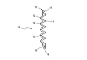
先ず、図1には、本発明に従う地中埋設物保護板10が、平面図の形態において概略的に示されており、また図2および図3には、図1におけるA−A切断線及びB−B切断線における地中埋設物保護板10の端面説明図が、それぞれ、示されている。そして、それら図1〜図3からも明らかなように、地中埋設物保護板10は、全体として略矩形の平面板形状とされていると共に、その板表面上に、多数の突起12が、千鳥状配列において配設されて、凹凸表面形状とされている。
First, FIG. 1 schematically shows a buried
より詳細には、地中埋設物保護板10は、ここでは、非常に硬い金属組織であるマルテンサイト組織中に、高硬質の炭化物である球状の炭化バナジウムを微細に且つ均一に分散せしめてなる合金白鋳鉄を用いて、長方形の平面板状において鋳造、形成されている。そして、図2及び図3に示されるように、そのような保護板10には、全体的に湾曲面形状をもって形成された楕円球面形状乃至は卵形形状の外面を有する、所定厚さを持った中空の突起12が、千鳥状配列をもって、板表面上に多数形成されていると共に、そのような突起12,12間は、平坦な板状部14として、構成されている。
More specifically, the buried
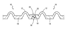
また、かかる地中埋設物保護板10の長方形形状の4つの辺部のうち、隣り合う二つの辺部16,16には、突起12の突出する方向(図2において、上向き)に開口する溝18,18が、それぞれ、辺部16の延びる方向に形成されている。一方、そのような辺部16,16と対向する他方の辺部20,20には、溝18に対応した形状とされて、溝18と凹凸嵌合可能な形状とされた突条22,22が、溝18の開口方向とは逆向きに、つまり図2において下向きに突出するように、辺部20の延びる方向に、それぞれ形成されている。
Of the four rectangular side portions of the underground buried
そして、このような凹凸表面形状とされた地中埋設物保護板10は、例えば、図7に示されるように、路面より比較的浅い地中に埋設される、情報ケーブル26等が収容された管路28と、アスファルトやコンクリート等の道路舗装との間に、板表面上に形成された突起12が上方に(路面側に)突出するようにして、埋設されて、使用されることとなるのである。
And the underground
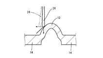
従って、このような本発明に従う地中埋設物保護板10にあっては、保護板10の表面上に多数配設された突起12に対して、作業機械の先端部が触れた場合、例えば、図4に概略的に示されるように、突起12の外周面に対して、コンクリートカッターのダイヤモンドブレード24が接触した際には、ダイヤモンドブレード24は突起12の湾曲面によって側方に逃げ、ダイヤモンドブレード24から、突起12へと加えられる下向きの力、即ち、地中埋設物保護板10を切断しようとする力は、ダイヤモンドブレード24が接触している突起12の楕円球面形状とされた外周面の傾斜によって、下向き方向と横向き方向とに分散せしめられ、そしてこの分散せしめられた横向きの力の発生によって、保護板10を切断しようとする力が効果的に減少せしめられ得ることとなるのであり、以て、地中埋設物保護板10の難切削性能や耐衝撃性能が向上せしめられることとなる。
Therefore, in the underground buried
しかも、本実施形態においては、それら複数の突起12が、保護板10の表面上において、千鳥状配列をもって、配設せしめられているところから、それら突起12,12間に形成される板状部14の面積が、突起12の面積よりも小さくなり、また水平方向に延びる直線部分の長さが短くなって、保護板10の上部から進入してくる作業機械の先端を突起12に接触せしめて、板状部14との接触を回避することが可能となるのであり、これによって、作業機械の先端の接触による保護板10の板状部14における切断の低減を、より効果的に図ることが出来るのである。
In addition, in the present embodiment, the plurality of
加えて、そのように保護板10の板表面上に多数配設されている突起12は、所定厚さを有した肉抜き構造とされているところから、かかる地中埋設物保護板10を製造するための必要な材料を効果的に減少せしめ得て、その製造に必要なコストを低減することが可能となると共に、保護板10全体の重量も有利に軽量化され得、施工時における作業性をも向上することが出来るのである。
In addition, since the
また、かかる地中埋設物保護板10の4つの辺部においては、対向する2つの辺部16と20のそれぞれに、溝18と突条22とが設けられているところから、複数の地中埋設物保護板10,10同士の辺部を重ね合わせて、図6に示すように、一方の保護板10の溝18内に、他方の保護板10の突条22を凹凸嵌合せしめることによって、容易に保護板10,10同士を連結することが可能となり、図5の如く、複数の保護板10を、長方形形状の4辺のどちらの方向にも、容易に連結していくことが出来るのである。また、この連結作業は、単に、溝18と突条22とを凹凸嵌合するだけで済むため、施工時の作業性が悪化してしまう恐れもない特徴を発揮する。
Further, in the four sides of the underground buried
しかも、そのような連結部においては、保護板10,10同士が凹凸嵌合部分で重ね合わされていて、その保護板10,10の継ぎ目となる部分に隙間が発生することがないところから、従来の如き構造の保護板のように、保護板同士の連結部分に発生する隙間から、作業機械の先端が保護板より下に侵入して、保護板の下に埋設された管路が切断されてしまう恐れも、効果的に解消され得ることとなるのである。
Moreover, in such a connecting portion, the
ところで、かかる地中埋設物保護板10を形成する材質である、金属組織であるマルテンサイト組織中に、非常に高硬度な炭化物である炭化バナジウムを微細に且つ球状に均一に分散させたものは、特開2002―275573号公報等に明らかにされているが、本実施の形態においては、以下の表1に示されるような化学成分配合が採用されている。そして、このような成分配合を持つ合金白鋳鉄としては、例えば、株式会社岡本より「STARK」なる名称にて商品化されており、そのような鋳鉄材料が、好適に採用され得ることとなる。また、かかる表1に示される合金白鋳鉄においては、引張り強さが700N/mm2 以上、ロックウエル硬さが50〜60HRCとされ、鉄系金属の持つ靱性と、炭化物の持つ高硬度を兼ね備えているため、前述した構造とされた地中埋設物保護板10の難切削性能や耐衝撃性能が、より一層向上することとなるのである。また、鋳造により製造されているので、使用済みの地中埋設物保護板10を回収して、再度溶解して鋳造を行うことにより、新たな地中埋設物保護板10として再生することが可能であり、リサイクルの促進にも貢献し得ることとなる。
By the way, in the martensite structure, which is a metal structure, which is a material forming the underground buried

また、本実施の形態においては、かかる地中埋設物保護板10は、長辺が約500mm、短辺が約250mmの長方形とされ、保護板10全体としての高さ(保護板10の底面から突起12の頂点までの高さ)は、約35mmの厚さとされている。また、突起12は、周方向の最大径が約40mm、その厚みが8mmとされて、形成されると共に、保護板10の表面上に多数形成される突起12,12間に位置する板状部18は、その厚みが15mm以上とされている。このように、地中埋設物保護板10が適度な大きさとされて、形成されているところから、生産時や施工時における作業性を有利に向上せしめることが可能となると共に、それら保護板10を、複数組み合わせることにより、施工現場に合わせた任意の長さや幅をもつ形状とすることが可能となるのである。また、突起12,12間における板状部18の厚さが15mm以上とされているので、作業機械の先端が、突起12を回避して保護板10に接触しても、保護板10が完全に切断されてしまう恐れが、有利に解消され得るのである。
In the present embodiment, the underground buried
以上、本発明の代表的な実施の形態について説明してきたが、本発明は、そのような実施形態のもののみに限定して解釈されるものでは決してなく、当業者の知識に基づいて種々なる変更、修正、改良等を加えた態様において実施され得るものであり、また、そのような実施態様が、本発明の趣旨を逸脱しない限り、何れも、本発明の範囲内に含まれるものであることは、言うまでもないところである。 The exemplary embodiments of the present invention have been described above. However, the present invention should not be construed as being limited to only such embodiments, and may vary based on the knowledge of those skilled in the art. The present invention can be implemented in a mode to which changes, modifications, improvements, and the like are added, and any such embodiment is included in the scope of the present invention without departing from the gist of the present invention. It goes without saying.
例えば、前述した実施形態においては、地中埋設物保護板10の外形形状は長方形とされていたが、正方形形状や、その他各種の多角形形状とすることも勿論可能である。そして、そのような保護板10は、鋳造手法にて製造される他、公知の各種の製造手法に従って形成され得るものである。
For example, in the embodiment described above, the outer shape of the underground buried
また、保護板10の板表面上に配設される突起12にあっても、保護板10の大きさや厚さに応じて、その直径や高さ、配設される個数が適宜決定されると共に、その外面形状も、少なくとも頂面が錐状乃至は湾曲面形状とされた外面形状を呈する限りにおいて、本実施の形態の如き楕円球面形状(卵形形状)の他、球面形状や円錐形状、三角錐形状等が、適宜に選択されて用いられることとなる。なお、そのような突起12の外面形状は、少なくともその頂部の頂面が錐状乃至は湾局面形状とされていることによって、作業機械の先端が接触すると、それが側方に逃げるようになるのである。
In addition, the diameter, height, and number of the
さらに、複数の保護板10の連結方式にあっても、図5に示される如く二方向に連結せしめられるようにした形態の他、一方向に直線的に連結せしめられる形態とすることも可能である。
Further, even if the plurality of
加えて、保護板10を形成する材質も、硬質の材質であって、それにより充分な難切削性能や耐衝撃性能を有するものであれば、前述した合金白鋳鉄の他、公知の各種のものが使用可能である。
In addition, the material forming the
10 地中埋設物保護板
12 突起
14 板状部
16 辺部
18 溝
20 辺部
22 突条
DESCRIPTION OF
Claims (6)
The underground buried object protection plate according to claim 5, wherein the plate-like portion located between the plurality of protrusions has a plate thickness of at least 15 mm.
Priority Applications (1)
| Application Number | Priority Date | Filing Date | Title |
|---|---|---|---|
| JP2004012382A JP4351077B2 (en) | 2004-01-20 | 2004-01-20 | Underground object protection plate |
Applications Claiming Priority (1)
| Application Number | Priority Date | Filing Date | Title |
|---|---|---|---|
| JP2004012382A JP4351077B2 (en) | 2004-01-20 | 2004-01-20 | Underground object protection plate |
Publications (2)
| Publication Number | Publication Date |
|---|---|
| JP2005207035A JP2005207035A (en) | 2005-08-04 |
| JP4351077B2 true JP4351077B2 (en) | 2009-10-28 |
Family
ID=34898771
Family Applications (1)
| Application Number | Title | Priority Date | Filing Date |
|---|---|---|---|
| JP2004012382A Expired - Fee Related JP4351077B2 (en) | 2004-01-20 | 2004-01-20 | Underground object protection plate |
Country Status (1)
| Country | Link |
|---|---|
| JP (1) | JP4351077B2 (en) |
Families Citing this family (3)
| Publication number | Priority date | Publication date | Assignee | Title |
|---|---|---|---|---|
| JP5611131B2 (en) * | 2011-06-29 | 2014-10-22 | 日本電信電話株式会社 | Cable protection member |
| KR101556942B1 (en) | 2014-10-29 | 2015-10-05 | 영진산업 주식회사 | Underground cable cover |
| CN111463737B (en) * | 2020-03-20 | 2021-04-09 | 嘉兴市平安电气工程有限公司 | Antidetonation formula cable centre gripping equipment |
-
2004
- 2004-01-20 JP JP2004012382A patent/JP4351077B2/en not_active Expired - Fee Related
Also Published As
| Publication number | Publication date |
|---|---|
| JP2005207035A (en) | 2005-08-04 |
Similar Documents
| Publication | Publication Date | Title |
|---|---|---|
| KR101206003B1 (en) | Breaking hammer, and fastening element, side plate, and protective casing of breaking hammer | |
| JP4351077B2 (en) | Underground object protection plate | |
| WO2022074770A1 (en) | Protective member and protection method | |
| JP5439278B2 (en) | How to remove temporary support concrete | |
| JP7429965B2 (en) | protection plate | |
| JP2021038545A (en) | Casing bit and casing pipe tip structure | |
| JP3228617U (en) | Protective plate | |
| JP4564020B2 (en) | Curb block | |
| JP2007037240A (en) | Buried object protecting plate | |
| JP2012246735A (en) | Tooth member and bucket for shovel type excavator | |
| JP3164718U (en) | Protection plate for cutting prevention | |
| JP3146972U (en) | Destruction hammer and its protective casing | |
| JP2005304198A (en) | Protective iron lid of superficial buried object for electric wire common duct | |
| JP7244967B1 (en) | How to remove the existing joint device | |
| JP2007143355A (en) | Ceramic protective board | |
| JP2006050795A (en) | Protective plate for prevention of cutting | |
| JP5468025B2 (en) | Buried object protection plate and buried object protection method | |
| JP5054407B2 (en) | Buried object protection plate and buried object protection plate installation structure | |
| JP4301803B2 (en) | Piping protector | |
| JP2006105254A (en) | Protective plate for underground structure | |
| CN107956232A (en) | Lithosphere ground is crushed with multibuchet hook-type bucket device | |
| JP2006064143A (en) | Protective board and protective structure for underground embedded object | |
| JP4502480B2 (en) | Excavation tool and wear-resistant member | |
| KR20100085893A (en) | Safety insulation cover for preventing rust (corrosion) and freezing of water supply pipe using waste plastic | |
| JP5068117B2 (en) | Laying structure and laying method for underground objects |
Legal Events
| Date | Code | Title | Description |
|---|---|---|---|
| A711 | Notification of change in applicant |
Free format text: JAPANESE INTERMEDIATE CODE: A711 Effective date: 20050425 |
|
| A521 | Written amendment |
Free format text: JAPANESE INTERMEDIATE CODE: A821 Effective date: 20050425 |
|
| A621 | Written request for application examination |
Free format text: JAPANESE INTERMEDIATE CODE: A621 Effective date: 20061020 |
|
| A977 | Report on retrieval |
Free format text: JAPANESE INTERMEDIATE CODE: A971007 Effective date: 20080710 |
|
| TRDD | Decision of grant or rejection written | ||
| A01 | Written decision to grant a patent or to grant a registration (utility model) |
Free format text: JAPANESE INTERMEDIATE CODE: A01 Effective date: 20090721 |
|
| A01 | Written decision to grant a patent or to grant a registration (utility model) |
Free format text: JAPANESE INTERMEDIATE CODE: A01 |
|
| A61 | First payment of annual fees (during grant procedure) |
Free format text: JAPANESE INTERMEDIATE CODE: A61 Effective date: 20090723 |
|
| FPAY | Renewal fee payment (event date is renewal date of database) |
Free format text: PAYMENT UNTIL: 20120731 Year of fee payment: 3 |
|
| R150 | Certificate of patent or registration of utility model |
Free format text: JAPANESE INTERMEDIATE CODE: R150 |
|
| LAPS | Cancellation because of no payment of annual fees |