JP4350101B2 - Lens grinding device with chamfering mechanism - Google Patents
Lens grinding device with chamfering mechanism Download PDFInfo
- Publication number
- JP4350101B2 JP4350101B2 JP2006080832A JP2006080832A JP4350101B2 JP 4350101 B2 JP4350101 B2 JP 4350101B2 JP 2006080832 A JP2006080832 A JP 2006080832A JP 2006080832 A JP2006080832 A JP 2006080832A JP 4350101 B2 JP4350101 B2 JP 4350101B2
- Authority
- JP
- Japan
- Prior art keywords
- chamfering
- grinding
- lens
- lens material
- tool
- Prior art date
- Legal status (The legal status is an assumption and is not a legal conclusion. Google has not performed a legal analysis and makes no representation as to the accuracy of the status listed.)
- Expired - Fee Related
Links
Images


Classifications
-
- B—PERFORMING OPERATIONS; TRANSPORTING
- B24—GRINDING; POLISHING
- B24B—MACHINES, DEVICES, OR PROCESSES FOR GRINDING OR POLISHING; DRESSING OR CONDITIONING OF ABRADING SURFACES; FEEDING OF GRINDING, POLISHING, OR LAPPING AGENTS
- B24B9/00—Machines or devices designed for grinding edges or bevels on work or for removing burrs; Accessories therefor
- B24B9/02—Machines or devices designed for grinding edges or bevels on work or for removing burrs; Accessories therefor characterised by a special design with respect to properties of materials specific to articles to be ground
- B24B9/06—Machines or devices designed for grinding edges or bevels on work or for removing burrs; Accessories therefor characterised by a special design with respect to properties of materials specific to articles to be ground of non-metallic inorganic material, e.g. stone, ceramics, porcelain
- B24B9/08—Machines or devices designed for grinding edges or bevels on work or for removing burrs; Accessories therefor characterised by a special design with respect to properties of materials specific to articles to be ground of non-metallic inorganic material, e.g. stone, ceramics, porcelain of glass
- B24B9/14—Machines or devices designed for grinding edges or bevels on work or for removing burrs; Accessories therefor characterised by a special design with respect to properties of materials specific to articles to be ground of non-metallic inorganic material, e.g. stone, ceramics, porcelain of glass of optical work, e.g. lenses, prisms
-
- B—PERFORMING OPERATIONS; TRANSPORTING
- B24—GRINDING; POLISHING
- B24B—MACHINES, DEVICES, OR PROCESSES FOR GRINDING OR POLISHING; DRESSING OR CONDITIONING OF ABRADING SURFACES; FEEDING OF GRINDING, POLISHING, OR LAPPING AGENTS
- B24B13/00—Machines or devices designed for grinding or polishing optical surfaces on lenses or surfaces of similar shape on other work; Accessories therefor
- B24B13/02—Machines or devices designed for grinding or polishing optical surfaces on lenses or surfaces of similar shape on other work; Accessories therefor by means of tools with abrading surfaces corresponding in shape with the lenses to be made
-
- B—PERFORMING OPERATIONS; TRANSPORTING
- B24—GRINDING; POLISHING
- B24B—MACHINES, DEVICES, OR PROCESSES FOR GRINDING OR POLISHING; DRESSING OR CONDITIONING OF ABRADING SURFACES; FEEDING OF GRINDING, POLISHING, OR LAPPING AGENTS
- B24B27/00—Other grinding machines or devices
- B24B27/0069—Other grinding machines or devices with means for feeding the work-pieces to the grinding tool, e.g. turntables, transfer means
-
- B—PERFORMING OPERATIONS; TRANSPORTING
- B24—GRINDING; POLISHING
- B24B—MACHINES, DEVICES, OR PROCESSES FOR GRINDING OR POLISHING; DRESSING OR CONDITIONING OF ABRADING SURFACES; FEEDING OF GRINDING, POLISHING, OR LAPPING AGENTS
- B24B49/00—Measuring or gauging equipment for controlling the feed movement of the grinding tool or work; Arrangements of indicating or measuring equipment, e.g. for indicating the start of the grinding operation
- B24B49/02—Measuring or gauging equipment for controlling the feed movement of the grinding tool or work; Arrangements of indicating or measuring equipment, e.g. for indicating the start of the grinding operation according to the instantaneous size and required size of the workpiece acted upon, the measuring or gauging being continuous or intermittent
Landscapes
- Engineering & Computer Science (AREA)
- Mechanical Engineering (AREA)
- Chemical & Material Sciences (AREA)
- Ceramic Engineering (AREA)
- Inorganic Chemistry (AREA)
- Grinding And Polishing Of Tertiary Curved Surfaces And Surfaces With Complex Shapes (AREA)
Description
本発明は、球面形状の研削面を備えた研削皿を用いて光学球面レンズを研削加工するレンズ研削装置に関する。さらに詳しくは、研削済みのレンズ素材に面取り加工を施すための面取り機構を備えたレンズ研削装置およびその使用方法に関する。 The present invention relates to a lens grinding apparatus that grinds an optical spherical lens by using a grinding pan having a spherical grinding surface. More specifically, the present invention relates to a lens grinding apparatus having a chamfering mechanism for chamfering a ground lens material and a method for using the same.
光学球面レンズの研削方法としては、カップ型砥石による球面創成方法が広く知られている。この方法では、図6に示すように、軸線100を中心として回転している加工対象のガラス素材101に、軸線102を中心として回転しているカップ型砥石103の球面研削面104を押し当てながら研削加工を施して、軸線100、102の交点を球心とする球面105を創成する。この加工方法は完全な球面創成方法であるが、カップ型砥石103の摩耗による曲率の狂い、ガラス素材101の研削面の中心部分に削り残りが発生するなどの問題点がある。
As a method for grinding an optical spherical lens, a spherical surface creation method using a cup-type grindstone is widely known. In this method, as shown in FIG. 6, the
本願出願人は特許文献1において、皿型砥石であるダイヤモンド工具を回転および球心揺動させて球面レンズを研削加工するレンズ研削方法を提案している。ここに開示のレンズ研削方法を採用すれば、カップ型砥石による球面創成方法において発生する問題を解消可能である。特に、大曲率のレンズ面の研削加工において、得られたレンズ面における曲率のばらつきを比較的少なく出来るという利点もある。 The present applicant has proposed a lens grinding method in Patent Document 1 in which a spherical tool is ground by rotating a diamond tool which is a dish-shaped grindstone and swinging a spherical center. If the lens grinding method disclosed here is employed, the problems that occur in the spherical surface creation method using a cup-type grindstone can be solved. In particular, there is also an advantage that variation in curvature on the obtained lens surface can be relatively reduced in grinding of a lens surface having a large curvature.
一方、光学球面レンズの面取装置としては、特許文献2において、カップ型砥石を用いたカーブジェネレータに付設され、レンズの球面加工と同時に面取りを行うことのできるレンズの外周面取装置が提案されている。また、特許文献3には、面取り対象の凹レンズの曲率半径より大きな曲率半径の凸形状の面取り用の砥石を回転させながら、面取り対象の凹レンズに押し当てて面取り加工を行う方法が提案されている。
ここで、カップ型砥石を用いた研削加工では、特許文献2に記載されているように、カーブジェネレータに、同時加工を行う面取装置を付設できるという利点がある。しかるに、特許文献1において提案されている皿型砥石を用いたレンズ研削加工は、カップ型砥石を用いた球面創成方法に比べて上記のように優れているが、同時面取りを行う面取り装置を付設できないという欠点がある。 Here, in grinding using a cup-type grindstone, as described in Patent Document 2, there is an advantage that a chamfering device that performs simultaneous machining can be attached to the curve generator. However, the lens grinding process using the dish type grindstone proposed in Patent Document 1 is superior to the spherical surface creation method using the cup type grindstone as described above, but a chamfering device for simultaneous chamfering is provided. There is a disadvantage that it can not.
このために、皿型砥石を用いたレンズ研削加工では、手作業により面取り作業を行うか、あるいは、砥石回転軸を備えた独立した面取加工装置を配置して、例えば特許文献3に示す方法により面取りを行う必要があった。
For this reason, in lens grinding using a dish-type grindstone, a chamfering operation is performed manually, or an independent chamfering device equipped with a grindstone rotating shaft is arranged, for example, a method shown in
本発明の課題は、この点に鑑みて、独立した面取加工装置を用いることなく、しかも、回転軸を増やすことなく、皿型砥石を用いた研削加工に引き続いて面取り加工を行うことのできる面取機構付きレンズ研削装置を提案することにある。 In view of this point, it is an object of the present invention to perform chamfering following grinding using a dish-type grindstone without using an independent chamfering apparatus and without increasing the rotation axis. The object is to propose a lens grinding apparatus with a chamfering mechanism.
上記の課題を解決するために、本発明の面取機構付きレンズ研削装置は、
球面形状の研削面を備えた研削皿と、
この研削皿を支持し、中心軸線が前記研削面の球心を通る状態に配置されている研削皿スピンドルと、
前記研削皿スピンドルを支持している球心揺動体と、
前記研削皿スピンドルの中心軸線が前記球心を頂点とする円錐面上を回転するように、前記球心揺動体を球心揺動させるための揺動機構と、
前記研削皿スピンドルを中心軸線回りに回転させるための研削皿回転機構と、
加工対象のレンズ素材を保持し、中心軸線が前記球心を通る状態に配置されているレンズホルダと、
このレンズホルダをその中心軸線に沿って前記研削皿に向けて送り出すためのワーク送り機構と、
当該ワーク送り機構による前記レンズホルダの送り動作を数値制御する数値制御部と、
前記レンズホルダをその中心軸線回りに回転させるためのワーク回転機構と、
前記レンズ素材を前記研削皿により研削することにより得られる研削済みレンズ素材の面取りを行う面取り機構とを有し、
当該面取り機構は、
円環状のテーパ状研削面を備えた面取り工具と、
前記面取り工具を、その中心軸線が前記レンズホルダの中心軸線に一致する面取り位置、および当該面取り位置から退避した退避位置に移動する工具移動機構と、
前記レンズホルダに対して前記面取り工具をそれらの中心軸線の方向に相対的に移動させる面取り用送り機構とを備えており、
前記研削済みレンズ素材が保持されている前記レンズホルダを前記研削皿から離れる方向に戻すと、当該研削済みレンズ素材と前記研削皿の間に、前記面取り工具を配置可能となっており、
前記数値制御部により、前記面取り工具に対する前記研削済みレンズ素材の送り量を制御して、前記研削済みレンズ素材の面の大きさを決めることを特徴としている。
In order to solve the above problems, the lens grinding apparatus with a chamfering mechanism of the present invention is:
A grinding pan with a spherical grinding surface;
A grinding pan spindle which supports the grinding pan and is arranged in a state where the central axis passes through the spherical center of the grinding surface;
A ball swinging body supporting the grinding plate spindle;
A rocking mechanism for rocking the spherical rocking body so that the central axis of the grinding pan spindle rotates on a conical surface having the spherical center as a vertex;
A grinding pan rotating mechanism for rotating the grinding pan spindle about a central axis;
A lens holder that holds the lens material to be processed and is arranged so that the center axis passes through the spherical center;
A workpiece feeding mechanism for feeding the lens holder along the central axis toward the grinding pan;
A numerical controller for numerically controlling the feeding operation of the lens holder by the workpiece feeding mechanism;
A workpiece rotation mechanism for rotating the lens holder around its central axis;
A chamfering mechanism for chamfering a ground lens material obtained by grinding the lens material with the grinding plate,
The chamfering mechanism is
A chamfering tool with an annular tapered grinding surface;
A tool moving mechanism for moving the chamfering tool to a chamfering position whose center axis coincides with the center axis of the lens holder, and a retreating position retracted from the chamfering position;
A chamfering feed mechanism for moving the chamfering tool relative to the lens holder in the direction of the center axis thereof,
When the lens holder holding the ground lens material is returned in a direction away from the grinding pan, the chamfering tool can be disposed between the ground lens material and the grinding pan .
The numerical control unit controls the feed amount of the ground lens material with respect to the chamfering tool to determine the size of the surface of the ground lens material .
この構成の面取機構付きレンズ研削装置では、次のようにして、球面レンズの研削加工および面取り加工が行われる。 In the lens grinding apparatus with a chamfering mechanism having this configuration, the spherical lens is ground and chamfered as follows.
まず、前記研削皿を回転させると共に球心揺動させ、前記レンズホルダに保持されているレンズ素材を所定の送り速度で送り出して、回転および球心揺動している前記研削皿の研削面に押し付け、前記研削皿に押し付けられた前記レンズ素材を所定の切削送り速度で送り出しながら、当該レンズ素材を研削加工する。 First, the grinding pan is rotated and the ball is pivoted, and the lens material held by the lens holder is fed out at a predetermined feed speed to the grinding surface of the grinding pan that is rotating and pivoting. The lens material is pressed while being fed to the grinding plate at a predetermined cutting feed speed.
次に、所定の研削加工を施すことにより得られた研削済みレンズ素材を、前記研削皿から離れる方向に戻す。 Next, the ground lens material obtained by performing a predetermined grinding process is returned in a direction away from the grinding pan.
しかる後に、前記面取り工具を、前記退避位置から移動させて前記面取り位置に位置決めし、前記レンズホルダに保持されている研削済みレンズ素材を送り出して前記面取り位置にある前記面取り工具の前記テーパ状研削面に押し付け、前記面取り工具に押し付けられた前記レンズ素材を所定の切削送り速度で送り出しながら、当該研削済みレンズ素材に対して面取り用の研削加工を施す。 Thereafter, the chamfering tool is moved from the retracted position to be positioned at the chamfering position, the ground lens material held by the lens holder is fed out, and the tapered grinding of the chamfering tool at the chamfering position is performed. The ground lens material is pressed against the surface and fed to the chamfering tool at a predetermined cutting feed speed, and the ground lens material is ground for chamfering.
このとき、前記数値制御部は、前記面取り工具の位置に対して数値を指示して、前記面取り工具に対する前記研削済みレンズ素材の送り量を定めた後、前記レンズホルダに保持されている前記研削済みレンズ素材を前記面取り工具に対して押圧移動させる。これにより、前記研削済みレンズ素材の面の大きさを制御する。At this time, the numerical control unit instructs a numerical value with respect to the position of the chamfering tool, determines a feed amount of the ground lens material to the chamfering tool, and then holds the grinding held by the lens holder. The finished lens material is pressed against the chamfering tool. Thereby, the size of the surface of the ground lens material is controlled.
そして、面取り加工後の面取り済みレンズ素材を前記面取り工具から離し、前記面取り工具を前記面取り位置から前記退避位置に退避させるようにすればよい。Then, the chamfered lens material after the chamfering process is separated from the chamfering tool, and the chamfering tool is retracted from the chamfering position to the retracted position.
本発明では、球面研削面を備えた研削皿を、その回転中心線が球面研削面の球心を頂点とする円錐面を描くように、球心揺動させながらレンズ素材を研削加工する。このように工具皿を揺動運動させることによって、小曲率の球面レンズ面を精度良く加工することができる。また、球面が研削加工された研削済みレンズ素材をレンズホルダから外すことなく、引き続き、面取加工を施すことができる。面取り加工においては、研削済みレンズ素材が保持されているレンズホルダを回転させればよいので、面取り加工のために回転軸を新たに設ける必要がない。よって、面取り加工を効率良く、しかも廉価な構成により行うことのできるレンズ研削装置を実現できる。In the present invention, the lens material is ground while the ball is rocked so that the center of rotation of the grinding pan provided with the spherical grinding surface draws a conical surface whose vertex is the spherical center of the spherical grinding surface. By swinging the tool plate in this way, a spherical lens surface with a small curvature can be processed with high accuracy. Further, chamfering can be continuously performed without removing the ground lens material whose spherical surface has been ground from the lens holder. In the chamfering process, it is only necessary to rotate the lens holder holding the ground lens material, so that it is not necessary to newly provide a rotation axis for the chamfering process. Therefore, it is possible to realize a lens grinding apparatus that can perform chamfering efficiently and at a low cost.
ここで、本発明において、前記工具移動機構は、直線状または曲線状の移動経路に沿って前記面取り工具を移動させるものであることを特徴としている。Here, in the present invention, the tool moving mechanism moves the chamfering tool along a linear or curved moving path.
また、前記面取り用送り機構は、前記ワーク送り機構、および/または、前記面取り工具を前記中心軸線の方向に往復移動させる面取り工具送り機構であることを特徴としている。Further, the chamfering feed mechanism is a chamfering tool feed mechanism that reciprocates the workpiece feed mechanism and / or the chamfering tool in the direction of the central axis.
本発明の面取機構付きレンズ研削装置においては、球面研削面を備えた研削皿を、その回転中心線が球面研削面の球心を頂点とする円錐面を描くように、球心揺動させながらレンズ素材を研削加工している。このように工具皿を揺動運動させることによって、小曲率の球面レンズ面を精度良く加工することができる。また、球面が研削加工された研削済みレンズ素材をレンズホルダから外すことなく、引き続き、面取加工を施すことができる。面取り加工においては、研削済みレンズ素材が保持されているレンズホルダを回転させればよいので、面取り加工のために回転軸を新たに設ける必要がない。よって、面取り加工を効率良く、しかも廉価な構成により行うことのできるレンズ研削装置を実現できる。 In the lens grinding apparatus with a chamfering mechanism of the present invention, the grinding pan provided with the spherical grinding surface is pivoted so that the rotation center line draws a conical surface having the spherical center of the spherical grinding surface as a vertex. However, the lens material is ground. By swinging the tool plate in this way, a spherical lens surface with a small curvature can be processed with high accuracy. Further, chamfering can be continuously performed without removing the ground lens material whose spherical surface has been ground from the lens holder. In the chamfering process, it is only necessary to rotate the lens holder holding the ground lens material, so that it is not necessary to newly provide a rotation axis for the chamfering process. Therefore, it is possible to realize a lens grinding apparatus that can perform chamfering efficiently and at a low cost.
以下に、図面を参照して、本発明を適用した面取機構付きレンズ研削装置の実施の形態を説明する。 Embodiments of a lens grinding apparatus with a chamfering mechanism to which the present invention is applied will be described below with reference to the drawings.
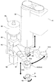
図1は、本実施の形態に係る光学球面レンズ研削用の面取機構付きレンズ研削装置の主要部分を示す概略構成図である。面取機構付きレンズ研削装置1は、加工対象のレンズ素材Wを保持するためのレンズホルダ3と、レンズホルダ3に保持されているレンズ素材Wを研削加工する球面研削面4aを備えた研削皿4を有している。また、面取り工具61を備えた面取機構60が付設されている。
FIG. 1 is a schematic configuration diagram showing a main part of a lens grinding apparatus with a chamfering mechanism for grinding an optical spherical lens according to the present embodiment. A lens grinding apparatus 1 with a chamfering mechanism includes a
レンズホルダ3はその保持面3aが下向きとなるように水平に保持された状態で、垂直なワークスピンドル5の下端に固定されている。ワークスピンドル5の中心にはその軸線方向に延びる吸引通路5aが形成されており、その下端がレンズホルダ3の保持面3aの中心に開口しており、その上端が回転継ぎ手6およびエアフィルタ7を経由して真空発生器8の吸引側に連通している。真空発生器8によって吸引通路5aを真空吸引することにより、レンズホルダ3の保持面3aにレンズ素材Wが吸着保持される。
The
ワークスピンドル5は、上端が封鎖されている円筒状の垂直保持筒9の内部に同軸状態に配置され、上下一対の軸受10、11を介して回転自在の状態で当該垂直保持筒9によって支持されている。また、ワークスピンドル5は、レンズ軸回転用電動機12によって、その垂直中心軸線であるレンズ回転中心線5Aを中心に回転駆動されるようになっている。垂直保持筒9の上端にはエアシリンダ13が連結されており、このエアシリンダ13は、上端が封鎖されている支持円筒14の内部に固定されている。エアシリンダ13によって垂直保持筒9が下方に所定の力で押圧されるようになっている。
The
ワークスピンドル5は、ワーク送り機構20によって昇降されるようになっている。ワーク送り機構20は水平アーム21を備えており、この水平アーム21の先端に取り付けた垂直円筒部22に、同軸状態で垂直保持筒9が挿入され、支持円筒14は水平アーム21の上面に固定されている。水平アーム21は送りねじ23、ナット24およびサーボモータ25を備えた昇降機構によって、垂直リニアガイド26に沿って昇降される。
The
ここで、エアシリンダ13を介してレンズスピンドル軸5を支持している支持円筒14には、その内側に装着されている垂直保持筒9の上端9aを検出するための近接センサ27が取り付けられている。通常は、この近接センサ27はオフ状態にあり、垂直保持筒9が支持円筒14に対して相対的に上昇すると、その上端9aが近接センサ27によって検出され、当該センサ出力がオンに切り替わる。
Here, a
次に、レンズホルダ3の下方に配置されている研削皿4は、その球面研削面4aの球心Oがレンズホルダ3側のレンズ回転中心線5A(ワークスピンドル5の中心軸線)の延長上に位置するように配置されている。この研削皿4の背面にはスピンドル4bが一体形成されており、このスピンドル4bは、球心揺動体31によって回転自在の状態で支持されている。ここで、研削皿4の回転中心線4A(スピンドル4bの中心軸線)が、球心Oにおいて、垂直に延びるレンズ回転中心線5Aに対して鋭角θで交差するように、スピンドル4bが球心揺動体31によって支持されている。
Next, in the grinding
球心揺動体31は、半球状のカップ部分31aと、このカップ部分31aの底中心の外周面部分から半径方向の外方に突出している円筒部分31bを備えており、円筒部分31bに同軸状態でスピンドル4bが回転自在の状態で取り付けられている。また、円筒部分31bの下端部からは横方にフランジ31cが延びており、ここに、スピンドル駆動用の電動機32が搭載されている。
The
球心揺動体31のカップ部分31aは、支持板33に形成された円環状内周面33aによって球心揺動可能な状態で支持されている。円環状内周面33aは、球心Oを球心とする球面であり、この円環状内周面33aに載せた外周面31dが球面のカップ部分31aは、球心Oを中心として揺動可能である。本例では、円環状内周面33aには圧縮空気吹き出し孔あるいは溝33bが形成されており、ここに、圧縮空気供給路33cを介して圧縮空気が供給されるようになっている。したがって、カップ部分31aは、円環状内周面33aから浮き上がった状態に保持される。よって、球心揺動体31を、球心Oを中心として円滑に揺動させることができる。
The
球心揺動体31の下端はリンク継ぎ手34および揺動幅調整ユニット35を介して、電動機36の出力軸に連結されている。球心揺動体31とリンク継ぎ手34の連結点34aは研削皿回転中心線4Aの延長線上に位置しており、電動機36の回転中心線36Aは常に球心Oを向く状態に保持されている。揺動幅調整ユニット35の調整つまみ35aを操作すると、連結点34aと電動機36の回転中心線36Aの間隔が変化する。よって、球心揺動体31の揺動運動の揺動幅を調整することができる。
The lower end of the
次に、電動機36は、揺動角調整ユニット37によって支持されている。揺動角調整ユニット37は、固定した位置に配置された弓形のカム38を備えており、このカム38は球心Oを中心とする円弧形状をしている。このカム38に沿って摺動可能な状態で、支持部材39が取り付けられており、ここに、電動機36が取り付けられている。支持部材39にはナット40が固定されており、ナット40には送りねじ41がねじ込まれている。送りねじ41の端部はハンドル42に連結されている。
Next, the
ハンドル42を回すと支持部材39がカム38に沿って移動する。すなわち、球心揺動体31によって支持されている研削皿スピンドル4bが球心Oを中心として所定量だけ揺動する。よって、揺動角調整ユニット37により、垂直なレンズ回転中心線5Aに対する研削皿4の回転中心線4Aのなす角度θ、すなわち、揺動中心線の角度を変更することができる。
When the
次に、図2は面取機構付きレンズ研削装置1の面取機構60の部分を示す部分斜視図である。図1および図2を参照して説明すると、本例の面取機構60の面取り工具61は、上方に広がったテーパ型の円環状研削面61aを備えたダイヤモンド工具であり、その中心軸線61bがレンズ回転中心線5Aと平行となるように工具アーム62の先端部に固定されている。工具アーム62の後端部は、垂直回転軸63に固定されており、この垂直回転軸63は、軸受け64を介して支持ブロック65によって回転自在の状態で支持されている。垂直回転軸63は支持ブロック65の上端面に取り付けたロータリアクチュエータ66によって回転駆動される。
Next, FIG. 2 is a partial perspective view showing a portion of the
ロータリアクチュエータ66によって垂直回転軸63が回転すると、そこから水平に延びている工具アーム62が水平方向に旋回し、その先端に取り付けられている面取り工具61を、その中心軸線61bがレンズ回転中心線5Aに一致した面取り位置61Aと、当該面取り位置61Aから横方に退避した退避位置61Bに移動させることができるようになっている。面取り工具61が退避位置61Bにある状態では、当該面取り工具61は、下方に送り出されるレンズホルダ3、およびそこに保持されているレンズ素材Wに干渉しないようになっている。
When the
また、支持ブロック65は昇降式スライダ67に支持されており、昇降式スライダ67は不図示の装置架台に固定されている垂直レール68に沿って昇降可能であり、エアーシリンダ69によって昇降させるようになっている。エアーシリンダ69を駆動して昇降式スライダ67を昇降させると、そこに取り付けられている支持ブロック65が昇降する。よって、支持ブロック65によって支持されている垂直回転軸63から水平に延びている工具アーム62も昇降し、当該工具アーム62の先端に取り付けられている面取り用工具61が昇降する。
The
次に、本例では、上記の各部分の駆動制御が数値制御用のコントローラ50によって行われるようになっている。コントローラ50には入力装置51が接続されており、数値を入力指定することにより、レンズホルダ3に保持されているレンズ素材Wの送り量および切削量、球面研削によって得られる研削済みレンズ素材W1の面取り加工時の送り量および面取り量などを決めることができる。また、入力装置51を介して、手動操作により、レンズ素材Wなどを送り出す動作を行うことができる。
Next, in this example, the drive control of each of the above parts is performed by the
(球面研削加工)
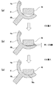
図3を参照して、本例の面取機構付きレンズ研削装置1の球面研削動作を説明する。まず、レンズ素材Wをレンズホルダ3に吸着保持させる。次に、手動操作によって、サーボモータ25を駆動して、研削皿4に向けてレンズ素材Wをジョグ(JOG)送りする。レンズ素材Wが研削皿4に接すると、ワークスピンドル5の下降が止まる。この後は、ジョグ送りによって水平アーム21(ワーク送りテーブル)のみが下降する。この結果、ワークスピンドル5および、これを回転自在に支持している垂直保持筒9が水平アーム21に対して相対的に上昇して、近接センサ27が垂直保持筒9の上端9aを検出してオンに切り替わる。
(Spherical grinding)
With reference to FIG. 3, the spherical grinding operation | movement of the lens grinding apparatus 1 with a chamfering mechanism of this example is demonstrated. First, the lens material W is attracted and held on the
近接センサ27がオンに切り替わったことを確認した後は、一旦、ジョグ送りを中止する。この後は、サーボモータ25の送り速度を超低速にして、水平アーム21を上昇させる。水平アーム21が上昇すると、停止しているワークスピンドル5および垂直保持筒9が相対的に近接センサ27に対して下降する。この結果、垂直保持筒の上端9aが近接センサ27の検出位置から外れて、近接センサ27が再びオフに戻る。このオフに切り替わった瞬間の位置を、コントローラ50は加工開始位置として記憶する。
After confirming that the
コントローラ50は、この加工開始位置から加工代を加算して加工完了位置を設定する。また、加工開始位置に第1切削量の分を加算して、速度変更点を設定する。このように各点を設定した後に、加工開始指令が入力されると、研削皿4およびレンズホルダ3に吸着固定したレンズ素材Wの回転を開始する。この後は、早送りで加工開始位置までレンズ素材Wを送り出す。
The
加工開始位置に到達した後は、速度を第1切削速度に切り替え、この速度でレンズ素材Wを送り出しながら研削を行う。図3(a)は研削開始時の状態を示してある。 After reaching the machining start position, the speed is switched to the first cutting speed, and grinding is performed while feeding the lens material W at this speed. FIG. 3 (a) shows a state at the start of grinding.
レンズ素材Wが第1切削量だけ切削され、第1切削位置に到達した後、すなわち、図3(b)に示すような切削状態に達した後は、球心揺動体31の揺動を開始し、第1切削速度よりも遅い仕上げ速度でレンズ素材Wを送り出しながら切削を行う。この結果、レンズ素材Wが研削されて、図3(c)に示すように球状レンズ面Waが形成された研削済みレンズ素材W1が得られる。 After the lens material W is cut by the first cutting amount and reaches the first cutting position, that is, after reaching the cutting state as shown in FIG. Then, cutting is performed while feeding the lens material W at a finishing speed slower than the first cutting speed. As a result, the lens material W is ground to obtain a ground lens material W1 having a spherical lens surface Wa as shown in FIG.
加工完了位置に到達したことが確認されると、球心揺動体31による揺動を停止した後、水平アーム21を上方に戻し、研削皿4の回転を止める。
When it is confirmed that the machining completion position has been reached, after the swinging by the
(面取り加工)
ここで、水平アーム21を上方へ戻して、その下端のレンズホルダ3に保持されている研削済みレンズ素材W1と、その下方の研削皿4の間に、横方から面取り工具61を挿入可能な間隔を確保する。また、ワークスピンドル5の回転を2000rpmから3000rpmに維持したままとする。すなわち、研削済みレンズ素材W1を2000rpmから3000rpmで回転させた状態を保持する。
(Chamfering)
Here, the
この後は、面取機構60のロータリアクチュエータ66を駆動して、工具アーム62を旋回して、その先端に取り付けられている面取り工具61を退避位置61Bから面取り位置61Aまで移動させ、当該面取り位置61Aに位置決めする。この状態では、面取り工具61の中心軸線61bがレンズ回転中心線5Aに一致する。図4には、この状態を示してある。
Thereafter, the
面取り工具61を位置決めした後に、ワーク送り機構20を駆動して、研削済みレンズ素材W1を下方に送り出して、面取り工具61の円環状研削面61aに押し付けて、面取り加工を開始する。面取り加工においては、面取り工具61の上下方向の位置を固定し、コントローラ50からの数値指示によりワークスピンドル5に保持されている研削済みレンズ素材W1の送り量を定め、所定の送り速度で研削済みレンズ素材W1の送りを行う。よって、コントローラ50からの数値指示によって面取り量が制御される。
After positioning the
面取り加工が終了した後は、ワーク送り機構20によって面取り済みレンズ素材を上方に退避させる。しかる後に、面取機構60のロータリアクチュエータ66を駆動して、面取り工具61を面取り位置61Aから退避位置61Bに向けて移動させ、当該退避位置61Bに戻す。
After the chamfering process is completed, the chamfered lens material is retracted upward by the
このように、本例の面取機構付きレンズ研削装置1では、球面研削加工に引き続いて、ワークスピンドル5のレンズホルダ3に保持されている研削済みレンズ素材W1に対して面取り加工を施すことができる。したがって、球面研削後に、レンズホルダ3から研削済みレンズ素材W1を取り外して面取装置の回転軸に取り付けて面取加工を行う場合、あるいは、レンズホルダ3から取り外した研削済みレンズ素材W1の面取りを手作業により行う場合とは異なり、面取り加工を効率良く行うことができる。また、面取装置を独立して設ける場合、あるいは、ワークスピンドルの他に面取り加工用の回転軸を設置する場合に比べて、廉価な構成の面取機構を構築できる。
Thus, in the lens grinding apparatus 1 with the chamfering mechanism of this example, the chamfering process is performed on the ground lens material W1 held by the
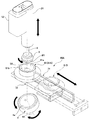
(面取機構の別の例)
図5は、面取機構60の別の例を示す斜視図である。この図に示す面取機構60Aは、スライド式のものであり、直線移動経路に沿って、面取り工具61を面取り位置61Aおよび退避位置61Bに移動させるようになっている。すなわち、面取機構60Aは、面取り工具61がガイドレール71に沿って水平方向の直線往復移動可能なスライダ72に支持されている。スライダ72は不図示のエアーシリンダなどの直動機構によって駆動されるようになっている。これ以外の部分は図1、2に示す例と同一であるので、対応する部位には同一の符号を付し、それらの説明は省略する。
(Another example of chamfering mechanism)
FIG. 5 is a perspective view showing another example of the
なお、面取機構60における面取り工具61を面取り位置61Aと退避位置61Bに移動させるための移動機構としては、上記のような円弧状の軌跡に沿って移動する旋回アーム式のもの、直線状の軌跡に沿って移動するスライド式のものの他、各種の移動機構を採用することができる。
In addition, as a moving mechanism for moving the
1 面取機構付きレンズ研削装置、3 レンズホルダ、4 研削皿、4a 球面研削面、4A 研削皿の回転中心線、5 ワークスピンドル、5A レンズ回転中心線、20 ワーク送り機構、21 水平アーム、31 球心揺動体、33 支持板、33a 円環状内周面、33b 圧縮空気吹き出し穴あるいは溝、35 揺動幅調整ユニット、36A 回転中心線、37 揺動角調整ユニット、60,60A 面取機構、61 面取り工具、61a テーパ型円環状研削面、61b 中心軸線、61A 面取り位置、61B 退避位置、62 工具アーム、63 垂直回転軸、64 軸受け、65 支持ブロック、66 ロータリアクチュエータ、67 スライダ、68 レール、69 エアーシリンダ、71 ガイドレール、72 スライダ、W レンズ素材、W1 研削済みレンズ素材、O 球心 DESCRIPTION OF SYMBOLS 1 Lens grinding apparatus with a chamfering mechanism, 3 Lens holder, 4 Grinding dish, 4a Spherical grinding surface, 4A Grinding dish rotation center line, 5 Work spindle, 5A Lens rotation center line, 20 Work feed mechanism, 21 Horizontal arm, 31 Ball swinging body, 33 support plate, 33a annular inner peripheral surface, 33b compressed air blowing hole or groove, 35 swing width adjusting unit, 36A rotation center line, 37 swing angle adjusting unit, 60, 60A chamfering mechanism, 61 Chamfering tool, 61a Tapered annular grinding surface, 61b Center axis, 61A Chamfering position, 61B Retraction position, 62 Tool arm, 63 Vertical rotation axis, 64 Bearing, 65 Support block, 66 Rotary actuator, 67 Slider, 68 Rail, 69 Air cylinder, 71 guide rail, 72 slider, W lens material, 1 grinding already lens material, O spherical center
Claims (4)
この研削皿を支持し、中心軸線が前記研削面の球心を通る状態に配置されている研削皿スピンドルと、
前記研削皿スピンドルを支持している球心揺動体と、
前記研削皿スピンドルの中心軸線が前記球心を頂点とする円錐面上を回転するように、前記球心揺動体を球心揺動させるための揺動機構と、
前記研削皿スピンドルを中心軸線回りに回転させるための研削皿回転機構と、
加工対象のレンズ素材を保持し、中心軸線が前記球心を通る状態に配置されているレンズホルダと、
このレンズホルダをその中心軸線に沿って前記研削皿に向けて送り出すためのワーク送り機構と、
当該ワーク送り機構による前記レンズホルダの送り動作を数値制御する数値制御部と、
前記レンズホルダをその中心軸線回りに回転させるためのワーク回転機構と、
前記レンズ素材を前記研削皿により研削することにより得られる研削済みレンズ素材の面取りを行う面取り機構とを有し、
当該面取り機構は、
円環状のテーパ状研削面を備えた面取り工具と、
前記面取り工具を、その中心軸線が前記レンズホルダの中心軸線に一致する面取り位置、および当該面取り位置から退避した退避位置に移動する工具移動機構と、
前記レンズホルダに対して前記面取り工具をそれらの中心軸線の方向に相対的に移動させる面取り用送り機構とを備えており、
前記研削済みレンズ素材が保持されている前記レンズホルダを前記研削皿から離れる方向に戻すと、当該研削済みレンズ素材と前記研削皿の間に、前記面取り工具を配置可能となっており、
前記数値制御部により、前記面取り工具に対する前記研削済みレンズ素材の送り量を制御して、前記研削済みレンズ素材の面の大きさを決めることを特徴とする面取り機構付きレンズ研削装置。 A grinding pan with a spherical grinding surface;
A grinding pan spindle which supports the grinding pan and is arranged in a state where the central axis passes through the spherical center of the grinding surface;
A ball swinging body supporting the grinding plate spindle;
A rocking mechanism for rocking the spherical rocking body so that the central axis of the grinding pan spindle rotates on a conical surface having the spherical center as a vertex;
A grinding pan rotating mechanism for rotating the grinding pan spindle about a central axis;
A lens holder that holds the lens material to be processed and is arranged so that the center axis passes through the spherical center;
A workpiece feeding mechanism for feeding the lens holder along the central axis toward the grinding pan;
A numerical controller for numerically controlling the feeding operation of the lens holder by the workpiece feeding mechanism;
A workpiece rotation mechanism for rotating the lens holder around its central axis;
A chamfering mechanism for chamfering a ground lens material obtained by grinding the lens material with the grinding plate,
The chamfering mechanism is
A chamfering tool with an annular tapered grinding surface;
A tool moving mechanism for moving the chamfering tool to a chamfering position whose center axis coincides with the center axis of the lens holder, and a retreating position retracted from the chamfering position;
A chamfering feed mechanism for moving the chamfering tool relative to the lens holder in the direction of the center axis thereof,
When the lens holder holding the ground lens material is returned in a direction away from the grinding pan, the chamfering tool can be disposed between the ground lens material and the grinding pan .
A lens grinding apparatus with a chamfering mechanism , wherein the numerical control unit controls a feed amount of the ground lens material to the chamfering tool to determine a size of a surface of the ground lens material .
前記工具移動機構は、直線状または曲線状の移動経路に沿って、前記面取り工具を移動させるものであることを特徴とする面取り機構付きレンズ研削装置。 In claim 1,
The tool grinding mechanism moves the chamfering tool along a linear or curved movement path, a lens grinding apparatus with a chamfering mechanism.
前記面取り用送り機構は、前記ワーク送り機構、および/または、前記面取り工具を前記中心軸線の方向に往復移動させる面取り工具送り機構であることを特徴とする面取り機構付きレンズ研削装置。 In claim 1,
The lens grinding apparatus with a chamfering mechanism, wherein the chamfering feed mechanism is a chamfering tool feed mechanism that reciprocates the work feed mechanism and / or the chamfering tool in the direction of the central axis.
前記研削皿を回転させると共に球心揺動させ、Rotate the grinding pan and swing the ball center,
前記レンズホルダに保持されているレンズ素材を所定の送り速度で送り出して、回転および球心揺動している前記研削皿の研削面に押し付け、Sending out the lens material held by the lens holder at a predetermined feed speed and pressing it against the grinding surface of the grinding pan that is rotating and pivoting around the ball,
前記研削皿に押し付けられた前記レンズ素材を所定の切削送り速度で送り出しながら、当該レンズ素材を研削加工し、While feeding the lens material pressed against the grinding pan at a predetermined cutting feed speed, grinding the lens material,
所定の研削加工を施すことにより得られた研削済みレンズ素材を、前記研削皿から離れる方向に戻し、The ground lens material obtained by applying a predetermined grinding process is returned in the direction away from the grinding pan,
前記面取り工具を、前記退避位置から移動させて前記面取り位置に位置決めし、The chamfering tool is moved from the retracted position to be positioned at the chamfering position,
前記レンズホルダに保持されている前記研削済みレンズ素材を送り出して前記面取り位置にある前記面取り工具の前記テーパ状研削面に押し付け、Feeding the ground lens material held by the lens holder and pressing it against the tapered grinding surface of the chamfering tool at the chamfering position;
前記数値制御部からの数値指示によって、前記面取り工具に対する前記研削済みレンズ素材の送り量を定め、By a numerical instruction from the numerical controller, a feed amount of the ground lens material to the chamfering tool is determined,
前記面取り工具に押し付けられた前記研削済みレンズ素材を所定の切削送り速度で送り出しながら、当該研削済みレンズ素材に対して面取り用の研削加工を施し、While feeding the ground lens material pressed against the chamfering tool at a predetermined cutting feed speed, the ground lens material is subjected to chamfering grinding,
面取り加工後の前記研削済みレンズ素材を前記面取り工具から離し、Release the ground lens material after chamfering from the chamfering tool,
しかる後に、前記面取り工具を前記面取り位置から前記退避位置に退避させることを特徴とする面取り機構付きレンズ研削装置の使用方法。Thereafter, the chamfering tool is retracted from the chamfering position to the retracted position, and the lens grinding apparatus with a chamfering mechanism is used.
Priority Applications (4)
| Application Number | Priority Date | Filing Date | Title |
|---|---|---|---|
| JP2006080832A JP4350101B2 (en) | 2006-03-23 | 2006-03-23 | Lens grinding device with chamfering mechanism |
| TW095114136A TW200735999A (en) | 2006-03-23 | 2006-04-20 | Lens grinding apparatus with chamfer mechanism |
| KR1020060039416A KR100803692B1 (en) | 2006-03-23 | 2006-05-02 | Lens grinding apparatus with chamfer mechanism |
| CNB2006100840620A CN100515674C (en) | 2006-03-23 | 2006-05-19 | Lens grinding apparatus with chamfer mechanism |
Applications Claiming Priority (1)
| Application Number | Priority Date | Filing Date | Title |
|---|---|---|---|
| JP2006080832A JP4350101B2 (en) | 2006-03-23 | 2006-03-23 | Lens grinding device with chamfering mechanism |
Publications (2)
| Publication Number | Publication Date |
|---|---|
| JP2007253279A JP2007253279A (en) | 2007-10-04 |
| JP4350101B2 true JP4350101B2 (en) | 2009-10-21 |
Family
ID=38628016
Family Applications (1)
| Application Number | Title | Priority Date | Filing Date |
|---|---|---|---|
| JP2006080832A Expired - Fee Related JP4350101B2 (en) | 2006-03-23 | 2006-03-23 | Lens grinding device with chamfering mechanism |
Country Status (4)
| Country | Link |
|---|---|
| JP (1) | JP4350101B2 (en) |
| KR (1) | KR100803692B1 (en) |
| CN (1) | CN100515674C (en) |
| TW (1) | TW200735999A (en) |
Families Citing this family (8)
| Publication number | Priority date | Publication date | Assignee | Title |
|---|---|---|---|---|
| JP2011235424A (en) * | 2010-05-13 | 2011-11-24 | Haruchika Seimitsu:Kk | Dish-shaped diamond grindstone and method for grinding spherical lens |
| CN103331672B (en) * | 2013-06-24 | 2015-09-09 | 满城县永红铸造机械有限公司 | Automatic grinding machine people |
| CN105666308B (en) * | 2014-11-17 | 2018-01-16 | 中国航空工业第六一八研究所 | A kind of speculum annular groove mouth chamfer grinding device and its Ginding process |
| CN105773344B (en) * | 2016-03-24 | 2018-07-20 | 淮安市岽盛光电仪器有限公司 | A kind of spherical surface glass polishing machine |
| CN106584236A (en) * | 2017-01-22 | 2017-04-26 | 福州紫凤光电科技有限公司 | Chamfering device of optical wafer |
| CN108161622B (en) * | 2018-01-10 | 2024-03-19 | 新兴河北工程技术有限公司 | Automatic chamfering and end face grinding device |
| CN109079626B (en) * | 2018-09-26 | 2024-07-16 | 苏州捷斯芬化妆用品有限公司 | Powder puff grinding device |
| CN111843770B (en) * | 2020-07-30 | 2021-12-17 | 佛山市金耀华玻璃新材有限公司 | Glass production surface refining treatment system and method |
Family Cites Families (5)
| Publication number | Priority date | Publication date | Assignee | Title |
|---|---|---|---|---|
| JPH02109671A (en) * | 1988-10-20 | 1990-04-23 | Olympus Optical Co Ltd | Lens grinding machine and lens working method |
| JPH02284874A (en) * | 1989-04-22 | 1990-11-22 | Olympus Optical Co Ltd | Grinding stone |
| JP2002126986A (en) | 2000-10-18 | 2002-05-08 | Canon Inc | Lens machining method |
| JP2002283203A (en) | 2001-03-26 | 2002-10-03 | Canon Inc | Rough cutting combined grinding wheel co-used for chamfering processing and processing method of optical element |
| JP2003340702A (en) | 2002-05-21 | 2003-12-02 | Haruchika Seimitsu:Kk | Diamond tool plate oscillation rotation-type lens polishing method and its device |
-
2006
- 2006-03-23 JP JP2006080832A patent/JP4350101B2/en not_active Expired - Fee Related
- 2006-04-20 TW TW095114136A patent/TW200735999A/en not_active IP Right Cessation
- 2006-05-02 KR KR1020060039416A patent/KR100803692B1/en not_active IP Right Cessation
- 2006-05-19 CN CNB2006100840620A patent/CN100515674C/en not_active Expired - Fee Related
Also Published As
| Publication number | Publication date |
|---|---|
| CN101041229A (en) | 2007-09-26 |
| KR20070096720A (en) | 2007-10-02 |
| CN100515674C (en) | 2009-07-22 |
| JP2007253279A (en) | 2007-10-04 |
| TWI295218B (en) | 2008-04-01 |
| KR100803692B1 (en) | 2008-02-20 |
| TW200735999A (en) | 2007-10-01 |
Similar Documents
| Publication | Publication Date | Title |
|---|---|---|
| JP4350101B2 (en) | Lens grinding device with chamfering mechanism | |
| JP2007253280A (en) | Grinding method for optical spherical lens | |
| US7281967B2 (en) | Machine for grinding optical lenses | |
| WO2013088884A1 (en) | Machine tool | |
| JP5476377B2 (en) | Lens processing equipment | |
| JPH11267956A (en) | Grinding machine | |
| JP5262576B2 (en) | Thread groove grinding device rest device and thread groove grinding device | |
| JP2013255980A (en) | End face polishing apparatus | |
| JP2006320970A (en) | Machining device | |
| KR100757627B1 (en) | Lens grinding method and lens grinding apparatus | |
| JP2006297512A (en) | Spherical machining device for lens | |
| JP4486898B2 (en) | Grinding method and grinding apparatus | |
| JP5010421B2 (en) | Centerless grinding method and centerless grinding apparatus for workpiece outer diameter surface and flat surface | |
| TWI296225B (en) | ||
| JP2009066724A (en) | Lens spherical face grinding method and device | |
| JPS59224257A (en) | Flexible polishing device | |
| JP2011131324A (en) | Cutting device and cutting method of the same | |
| JP2000326224A (en) | Grinding machine | |
| JP6135287B2 (en) | Grinder | |
| JP2002355750A (en) | Facing device and facing method | |
| CN114310536B (en) | Polishing method and polishing device for joint of spliced bathtub | |
| JP2008073822A (en) | Grinding method of peripheral edge of glass plate and device thereof | |
| JP2021171876A (en) | Processing machine and processing method | |
| JPH11114817A (en) | Grinding work method and grinder and grinding system | |
| JP2003127060A (en) | Curved surface machining machine for work, curved surface machining method, and curved surface machining grinding wheel |
Legal Events
| Date | Code | Title | Description |
|---|---|---|---|
| A977 | Report on retrieval |
Free format text: JAPANESE INTERMEDIATE CODE: A971007 Effective date: 20080402 |
|
| A131 | Notification of reasons for refusal |
Free format text: JAPANESE INTERMEDIATE CODE: A131 Effective date: 20090407 |
|
| A521 | Written amendment |
Free format text: JAPANESE INTERMEDIATE CODE: A523 Effective date: 20090522 |
|
| TRDD | Decision of grant or rejection written | ||
| A01 | Written decision to grant a patent or to grant a registration (utility model) |
Free format text: JAPANESE INTERMEDIATE CODE: A01 Effective date: 20090714 |
|
| A01 | Written decision to grant a patent or to grant a registration (utility model) |
Free format text: JAPANESE INTERMEDIATE CODE: A01 |
|
| A61 | First payment of annual fees (during grant procedure) |
Free format text: JAPANESE INTERMEDIATE CODE: A61 Effective date: 20090721 |
|
| FPAY | Renewal fee payment (event date is renewal date of database) |
Free format text: PAYMENT UNTIL: 20120731 Year of fee payment: 3 |
|
| R150 | Certificate of patent or registration of utility model |
Free format text: JAPANESE INTERMEDIATE CODE: R150 |
|
| FPAY | Renewal fee payment (event date is renewal date of database) |
Free format text: PAYMENT UNTIL: 20150731 Year of fee payment: 6 |
|
| R250 | Receipt of annual fees |
Free format text: JAPANESE INTERMEDIATE CODE: R250 |
|
| R250 | Receipt of annual fees |
Free format text: JAPANESE INTERMEDIATE CODE: R250 |
|
| LAPS | Cancellation because of no payment of annual fees |