JP4350025B2 - Lever device for chair and chair provided with the same - Google Patents
Lever device for chair and chair provided with the same Download PDFInfo
- Publication number
- JP4350025B2 JP4350025B2 JP2004327213A JP2004327213A JP4350025B2 JP 4350025 B2 JP4350025 B2 JP 4350025B2 JP 2004327213 A JP2004327213 A JP 2004327213A JP 2004327213 A JP2004327213 A JP 2004327213A JP 4350025 B2 JP4350025 B2 JP 4350025B2
- Authority
- JP
- Japan
- Prior art keywords
- chair
- latch mechanism
- movable part
- lever device
- operation unit
- Prior art date
- Legal status (The legal status is an assumption and is not a legal conclusion. Google has not performed a legal analysis and makes no representation as to the accuracy of the status listed.)
- Active
Links
Images
Landscapes
- Chairs Characterized By Structure (AREA)
Description
本発明は、椅子の座体や背もたれなどの可動部の位置調整を行う調整機構のロックを解除する椅子用レバー装置及びこれを備えた椅子に関するものである。 The present invention relates to a chair lever device for unlocking an adjustment mechanism that adjusts the position of a movable part such as a chair body and a backrest of a chair, and a chair provided with the same.
椅子の座体や背もたれなどの可動部の位置調整を可能にした椅子が広く普及しているが、この種の椅子では、良好な座り心地を確保するために設けられるガススプリングにロック機構付きのものを採用し、平時はそのガススプリングをロック状態とすることで座体や背もたれの位置が固定されるようになっている。 Chairs that can adjust the position of moving parts such as the seat and back of the chair are widely used, but this type of chair has a lock mechanism on the gas spring that is provided to ensure good sitting comfort. In the normal time, the position of the seat and the backrest is fixed by locking the gas spring.
ガススプリングは、適宜な付勢力によりロック状態に保持され、座体や背もたれなどの可動部の位置調整を行う際には、座体の下側に配置された操作レバーで解除操作を行うようにしており、このとき、片方の手で操作レバーを引いた状態で残りの手で体を支えるなどして調整作業を行うものが一般的であるが、調整作業の間、操作レバーから手を離してもロック解除状態に保持されるようにすると、両手が自由になるため、調整作業が容易になる利点が得られ、このような観点から、ワイヤをロック解除位置に牽引した状態で操作レバーを停止保持させるようにしたレバー装置が知られている(特許文献1参照)。
しかしながら、前記従来の技術では、操作レバーに設けられた係止軸をグリッパに圧入固定させる構成のものであるため、十分な保持力を確保するには、グリッパの弾発係止力を大きく設定する必要があり、このために大きな操作力が必要になり、操作性の面で難点があった。 However, in the conventional technique, the locking shaft provided on the operation lever is configured to be press-fitted and fixed to the gripper. Therefore, in order to secure a sufficient holding force, the elastic locking force of the gripper is set large. For this reason, a large operating force is required, which is difficult in terms of operability.
本発明は、このような従来技術の問題点を解消するべく案出されたものであり、その主な目的は、椅子の座体や背もたれなどの可動部の位置調整を行う調整機構のロックを解除した状態に停止保持させる構成で、良好な操作性を確保することができるように構成された椅子用レバー装置及びこれを備えた椅子を提供することにある。さらに本発明は、椅子の可動部の位置調整を行う調整機構のロックを解除した状態に停止保持させる構成で生じる種々の不都合を解消することも目的としている。 The present invention has been devised to solve such problems of the prior art, and its main purpose is to lock an adjustment mechanism for adjusting the position of a movable part such as a chair seat or backrest. An object of the present invention is to provide a chair lever device configured to be able to ensure good operability with a configuration in which it is stopped and held in a released state, and a chair provided with the chair lever device. Another object of the present invention is to eliminate various inconveniences caused by the configuration in which the lock of the adjustment mechanism for adjusting the position of the movable part of the chair is released and held.
このような課題を解決するために、本発明においては、請求項1に示すとおり、椅子の可動部の位置調整を行う調整機構のロックを解除するロック解除手段(10・21)に連動手段(26)を介して連結されて、前記ロック解除手段をロック状態に保持する付勢力に抗した操作部(45)の操作により前記連動手段をロック解除位置に変位させて前記可動部の位置調整を可能にする椅子用レバー装置において、前記連動手段をロック解除位置に停止保持させるラッチ機構(40)を備え、このラッチ機構による位置保持状態において前記操作部が初期位置に復帰するように、前記操作部が形成された操作部材(32)が、前記ラッチ機構を構成する部材(31)に対して所要の範囲で変位可能に設けられたものとした。
In order to solve such a problem, in the present invention, as shown in
これによると、ラッチ機構が位置保持状態となった後も操作部が初期位置に復帰するため、操作部が突出して調整作業の邪魔になったり、あるいは操作部に作用する外力でラッチ機構が損傷を受けることを避けることができる。 According to this, since the operation unit returns to the initial position even after the latch mechanism is in the position holding state, the operation unit protrudes and interferes with the adjustment work, or the latch mechanism is damaged by an external force acting on the operation unit. You can avoid receiving.
この場合、操作部材、並びにラッチ機構を構成するワイヤ牽引部材を、同一の支軸回りに回動可能に設けると共に、操作部材及びワイヤ牽引部材の相対変位を所要の範囲で許容する手段を、支軸を中心とする円弧状に湾曲した形状に形成されたガイド溝孔と、このガイド溝孔に嵌入する突起とで構成し、操作部材及びワイヤ牽引部材のいずれかの一方にガイド溝孔を、いずれか他方に突起を設けるようにすると良く、これにより簡易な構成で円滑な動作を確保することができる。 In this case, the operation member and the wire pulling member constituting the latch mechanism are provided so as to be rotatable around the same support shaft, and means for allowing the relative displacement between the operation member and the wire pulling member within a required range is provided. The guide groove is formed in a curved shape that is curved in an arc shape around the axis, and a protrusion that fits into the guide groove, and the guide groove is formed in one of the operation member and the wire pulling member. Protrusions may be provided on either one of the other, thereby ensuring a smooth operation with a simple configuration.
また、本発明においては、請求項2に示すとおり、可動部の位置調整を行う調整機構のロックを解除するロック解除手段に連動手段を介して連結されて、前記ロック解除手段をロック状態に保持する付勢力に抗した操作部の操作により前記連動手段をロック解除位置に変位させて前記可動部の位置調整を可能にするレバー装置を備えた椅子において、前記連動手段をロック解除位置に停止保持させるラッチ機構を備え、このラッチ機構による位置保持状態において前記操作部が初期位置に復帰するように、前記操作部が形成された操作部材が、前記ラッチ機構を構成する部材に対して所要の範囲で変位可能に設けられたものとした。
Further, according to the present invention, as shown in
これによると、ラッチ機構が位置保持状態となった後も操作部が初期位置に復帰するため、操作部が突出して調整作業の邪魔になったり、あるいは操作部に作用する外力でラッチ機構が損傷を受けることを避けることができる。 According to this, since the operation unit returns to the initial position even after the latch mechanism is in the position holding state, the operation unit protrudes and interferes with the adjustment work, or the latch mechanism is damaged by an external force acting on the operation unit. You can avoid receiving.
前記椅子においては、請求項3に示すとおり、前記可動部が、脚体(3)に対して昇降可能に設けられた座体(1)であり、前記調整機構が、前記座体の高さ位置を調整するものである構成とすることができる。また請求項4に示すとおり、前記可動部が、基体(2)に対して傾動可能に設けられた背もたれ(13)であり、前記調整機構が、前記背もたれの角度位置を調整するものである構成とすることができる。
In the chair, as shown in
このように本発明によれば、連動手段をロック解除位置に停止保持させる操作、並びにその位置保持状態を解除して元に戻す操作において、特に大きな操作力を必要としないため、操作性を向上させる上で大きな効果が得られる。 As described above, according to the present invention, in the operation of stopping and holding the interlocking unit at the unlocked position and the operation of releasing the position holding state and returning it to the original state, a particularly large operating force is not required, so that operability is improved. A great effect can be obtained.
以下、本発明の実施の形態を、図面を参照しながら説明する。 Hereinafter, embodiments of the present invention will be described with reference to the drawings.
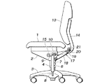
図1は、本発明が適用される事務用椅子を示す模式的な側面図である。この事務用椅子では、座体1を保持する基体2が、脚体3上に設けられた脚柱4を介して鉛直線回りに回転可能に支持されており、この脚柱4は、互いに上下動可能な筒体の内部にロック機構付のガススプリング6を備え、脚体3に対して基体2を昇降可能に支持している。ガススプリング6は、シリンダ7を基体2に対して固定されると共に、ピストンロッド8を脚体3に対して固定されている。
FIG. 1 is a schematic side view showing an office chair to which the present invention is applied. In this office chair, a
ガススプリング6では、内部のバルブを開閉するプッシュロッド9がシリンダ7の上端から突出した状態で設けられており、このプッシュロッド9の近傍には、プッシュロッド9を押し込み動作させる押圧機構(ロック解除手段)10が設けられている。ガススプリング6は、ばね付勢によりプッシュロッド9が突出位置にある平時には、内部のバルブが閉じてシリンダ7に対するピストンロッド8の進退を拘束するロック状態となるため、脚体3に対する基体2の昇降が不能であり、他方、押圧機構10によりプッシュロッド9が押し込まれると、バルブが開いてシリンダ7に対するピストンロッド8の進退が許容されるロック解除状態となり、これにより脚体3に対する基体2の昇降が可能となり、座体1の高さ調整を行うことができる。
In the
またこの事務用椅子では、背もたれ13を保持する背フレーム14が、基体2に対して支軸15を介して前後に傾動可能に支持されており、背フレーム14の下部には、ロック機構付のガススプリング17が設けられており、このガススプリング17は、シリンダ18を基体2に対して固定されると共に、ピストンロッド19を背フレーム14に対して固定されている。
Further, in this office chair, a
ガススプリング17では、ピストンロッド19の先端部からプッシュロッド20が突出した状態で設けられており、このプッシュロッド20の近傍に、プッシュロッド20を押し込み動作させる押圧機構(ロック解除手段)21が設けられている。このガススプリング17も、前記のガススプリング6と同様、プッシュロッド20が突出位置にある平時にはロック状態となるため、基体2に対する背フレーム14の傾動が不能であり、押圧機構21によりプッシュロッド20が押し込まれるとロック解除状態となり、これにより基体2に対する背フレーム14の傾動が可能となり、背もたれ13の角度調整を行うことができる。
The
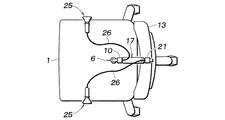
図2は、図1に示した事務用椅子の模式的な上面図である。この事務用椅子では、座体の下側に、本発明によるレバー装置25が配置されている。これらのレバー装置25はそれぞれ、座体1の高さ調整用のガススプリング6に対応する押圧機構10、並びに背もたれ13の角度調整用のガススプリング17に対応する押圧機構21にワイヤ(連動手段)26を介して連結されており、レバー装置25をそれぞれ操作すると、ワイヤ26が牽引されて押圧機構10・21がガススプリング6・17の各プッシュロッドを押し込み動作させ、座体1の高さ調整並びに背もたれ13の角度調整を行うことができる。
FIG. 2 is a schematic top view of the office chair shown in FIG. In this office chair, the
図3は、図2に示したレバー装置を詳しく示す断面図であり、動作状況を段階的に示している。このレバー装置25は、ワイヤ26の末端が連結されるワイヤ牽引部材31と、ワイヤ26を牽引する向きにワイヤ牽引部材31を動作させる操作部材32と、ワイヤ牽引部材31及び操作部材32を回動可能に支持するケース体33とを有している。ケース体33は、図2に示したように、座体1の下側で基体2の適所に固定される。
FIG. 3 is a cross-sectional view showing the lever device shown in FIG. 2 in detail, and shows the operation status step by step. The
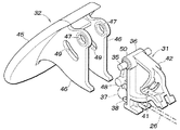
図4は、図3に示したワイヤ牽引部材及び操作部材を分解して示す斜視図である。ワイヤ牽引部材31は、支軸35が挿通される軸受け部36と、ワイヤ26の末端の係止球37を保持するワイヤ係止部38と、後に詳述するようにワイヤ26をロック解除位置に停止保持するためのラッチ機構40を構成するカム溝41が形成された扇形状部42とを有しており、合成樹脂材の射出成形により一体に形成されたものである。
FIG. 4 is an exploded perspective view showing the wire pulling member and the operation member shown in FIG. The
操作部材32は、下面側に手指を掛けて引き上げ操作可能な操作部45と、支軸35回りに回動可能に設けられると共にワイヤ牽引部材31に対して係合する連結板部46とを有しており、合成樹脂材の射出成形により一体に形成されたものである。連結板部46は、ワイヤ牽引部材31を挟み込むように一対設けられており、ワイヤ牽引部材31の軸受け部36の軸方向の端部に嵌合する円孔47、並びにワイヤ牽引部材31に設けられた突起48が嵌合する長孔49が開設されている。ワイヤ牽引部材31の突起48は、支軸35の軸線方向の両側に突出形成されており、一対の連結板部46の各長孔49に内側から嵌入する。またワイヤ牽引部材31の軸受け部36には、軸方向の両端に縮径部50が形成されており、この縮径部50が一対の連結板部46の各円孔47に内側から嵌入する。
The
長孔49は、支軸35を中心とする円弧状に湾曲した形状に形成され、ワイヤ牽引部材31の突起48が所定の角度範囲で自由に相対移動可能となっており、図3(A)に示すように、ワイヤ牽引部材31がワイヤ26をロック位置とする状態では、長孔49の端に突起48が位置するため、引き上げ操作による操作部材32の回動に応じてワイヤ牽引部材31が回動してワイヤ26を牽引することができる。
The
そして、操作部材32を引き上げ操作することにより、図3(B)に示すように、ワイヤ牽引部材31がワイヤ26をロック解除位置に停止保持する位置に変位した状態では、長孔49によりワイヤ牽引部材31の突起48で操作部材32の降下方向の回動が阻止されないため、図3(C)に示すように、操作部材32を図3(A)の状態と同様の初期位置に復帰させることができる。
Then, by pulling up the operating
図5は、図3に示したラッチ機構を分解して詳しく示す斜視図である。このラッチ機構40は、ワイヤ牽引部材31の側面に形成されたカム溝41と、このカム溝41に先端部52aが嵌入するトレースピン(トレース部材)52と、このトレースピン52を外側から押圧してカム溝41の底面に先端部52aが常時当接した状態に保持する板ばね53とからなっている。
FIG. 5 is an exploded perspective view showing the latch mechanism shown in FIG. 3 in detail. The
トレースピン52は、基端部52bをケース体33側の取付孔に嵌合させてケース体33に回動可能に取り付けられ、このトレースピン52の離脱を阻止する態様で板ばね53がねじ54でケース体33に固定される。
The
カム溝41は、往路部55及び復路部56が、ハート形状の外径輪郭を有するハート島57を取り囲むように設けられており、ハート島57の凸部に対応する第1の係止部59と、ハート島57の凹部に対応する第2の係止部60と、往路側並びに復路側のスイッチバック部61・62とを有している。カム溝41の底面には適所にトレースピン52の先端部52aが逆方向へ移動することを阻止する段差が設けられている。
The
ワイヤ牽引部材31がワイヤ26をロック位置とする状態(図3(A)参照)では、トレースピン52の先端部52aがカム溝41の第1の係止部59に位置し、この状態では、トレースピン52の先端部52aが復路部56へ進入することが段差で規制されるため、操作部材32の引き上げ操作が行われると、トレースピン52の先端部52aは往路部55に進入する。そしてトレースピン52の先端部52aが往路側のスイッチバック部61に到達したところで先端部52aの移動が規制されてワイヤ牽引部材31の回動が阻止される(図3(B)参照)。
In the state where the
この状態では、トレースピン52の先端部52aが往路部55へ戻ることが段差で規制されるため、操作部材32の引き上げ操作をやめると、ワイヤ26に引っ張られてワイヤ牽引部材31が回動するのに伴って、トレースピン52の先端部52aは第2の係止部60側に進入し、トレースピン52の先端部52aが第2の係止部60に到達したところで先端部52aの移動が規制されてワイヤ牽引部材31の回動が阻止され、ワイヤ26をロック解除位置に停止保持する状態となる(図3(C)参照)。
In this state, the step is regulated by the step so that the
この状態では、トレースピン52の先端部52aが往路側のスイッチバック部61へ戻ることが段差で規制されるため、操作部材32の引き上げ操作が行われると、トレースピン52の先端部52aは復路側のスイッチバック部62に進入する。そしてこの復路側のスイッチバック部62でワイヤ牽引部材31の回動が阻止されたところで先端部52aの移動が規制されてワイヤ牽引部材31の回動が阻止される。
In this state, the
この状態では、トレースピン52の先端部52aが第2の係止部60側に戻ることが段差で規制されるため、操作部材32の引き上げ操作をやめると、ワイヤ26に引っ張られてワイヤ牽引部材31が回動するのに伴って、トレースピン52の先端部52aは復路部56に進入して第1の係止部59に到達し、ワイヤ牽引部材31がワイヤ26をロック位置とする元の状態に戻る。
In this state, because the
本発明にかかる椅子用レバー装置は、椅子の座体や背もたれなどの可動部の位置調整を行う調整機構のロックを解除する用途に有用である。また、本発明にかかる椅子は、前記のように事務用椅子などとして有用である。なお、レバー装置は、前記のように座体の高さ調整や背もたれの角度調整の用途の他、座体の角度や前後位置の調整、あるいは肘掛けの高さ調整など、椅子の可動部の多様な位置調整の用途に広く適用することができる。 The lever device for a chair according to the present invention is useful for unlocking an adjustment mechanism that adjusts the position of a movable part such as a chair body or a backrest of the chair. Moreover, the chair concerning this invention is useful as an office chair etc. as mentioned above. In addition to the use of adjusting the height of the seat and the angle of the backrest as described above, the lever device can be used for various movable parts of the chair, such as adjusting the angle of the seat, the front and rear position, or the height of the armrest. Therefore, it can be widely applied to various uses for position adjustment.
1 座体
2 基体
3 脚体
6 ガススプリング
9・20 プッシュロッド
10・21 押圧機構(ロック解除手段)
13 背もたれ
25 レバー装置
26 ワイヤ(連動手段)
31 ワイヤ牽引部材
32 操作部材
40 ラッチ機構
41 カム溝
45 操作部
52 トレースピン(トレース部材)、52a 先端部、52b 基端部
DESCRIPTION OF
13
31
Claims (4)
前記連動手段をロック解除位置に停止保持させるラッチ機構を備え、このラッチ機構による位置保持状態において前記操作部が初期位置に復帰するように、前記操作部が形成された操作部材が、前記ラッチ機構を構成する部材に対して所要の範囲で変位可能に設けられたことを特徴とする椅子用レバー装置。 It is connected to the unlocking means for releasing the lock of the adjusting mechanism for adjusting the position of the movable part of the chair through the interlocking means, and the operation part is operated by operating the operating part against the urging force for holding the unlocking means in the locked state. A lever device for a chair that displaces the interlocking means to the unlocked position to enable position adjustment of the movable part,
A latch mechanism that stops and holds the interlocking unit at the unlocked position, and the operation member formed with the operation unit is configured to have the latch mechanism so that the operation unit returns to the initial position in a position holding state by the latch mechanism; A lever device for a chair, characterized in that it is provided so as to be displaceable within a required range with respect to members constituting the chair.
前記連動手段をロック解除位置に停止保持させるラッチ機構を備え、このラッチ機構による位置保持状態において前記操作部が初期位置に復帰するように、前記操作部が形成された操作部材が、前記ラッチ機構を構成する部材に対して所要の範囲で変位可能に設けられたことを特徴とする椅子。 The interlocking means is connected to an unlocking means for unlocking an adjusting mechanism for adjusting the position of the movable part via an interlocking means, and the interlocking means is operated by an operation unit against an urging force for holding the unlocking means in a locked state. A chair provided with a lever device that allows the position of the movable part to be adjusted by displacing it to the unlocking position,
A latch mechanism that stops and holds the interlocking unit at the unlocked position, and the operation member formed with the operation unit is configured to include the latch mechanism so that the operation unit returns to the initial position in a position holding state by the latch mechanism; A chair provided so as to be displaceable within a required range with respect to the members constituting the .
Priority Applications (1)
| Application Number | Priority Date | Filing Date | Title |
|---|---|---|---|
| JP2004327213A JP4350025B2 (en) | 2004-11-11 | 2004-11-11 | Lever device for chair and chair provided with the same |
Applications Claiming Priority (1)
| Application Number | Priority Date | Filing Date | Title |
|---|---|---|---|
| JP2004327213A JP4350025B2 (en) | 2004-11-11 | 2004-11-11 | Lever device for chair and chair provided with the same |
Publications (2)
| Publication Number | Publication Date |
|---|---|
| JP2006136437A JP2006136437A (en) | 2006-06-01 |
| JP4350025B2 true JP4350025B2 (en) | 2009-10-21 |
Family
ID=36617617
Family Applications (1)
| Application Number | Title | Priority Date | Filing Date |
|---|---|---|---|
| JP2004327213A Active JP4350025B2 (en) | 2004-11-11 | 2004-11-11 | Lever device for chair and chair provided with the same |
Country Status (1)
| Country | Link |
|---|---|
| JP (1) | JP4350025B2 (en) |
Families Citing this family (5)
| Publication number | Priority date | Publication date | Assignee | Title |
|---|---|---|---|---|
| JP5014677B2 (en) * | 2006-06-13 | 2012-08-29 | 株式会社岡村製作所 | Operation lever device in a chair |
| JP5114725B2 (en) * | 2006-08-28 | 2013-01-09 | コクヨ株式会社 | Chair |
| JP2008049079A (en) * | 2006-08-28 | 2008-03-06 | Kokuyo Co Ltd | Rocking mechanism and chair |
| JP6009891B2 (en) | 2011-11-04 | 2016-10-19 | 株式会社岡村製作所 | Chair |
| CN105476315B (en) * | 2015-12-15 | 2018-03-23 | 浙江安吉祥泰家具有限公司 | A kind of improved chair tray |
-
2004
- 2004-11-11 JP JP2004327213A patent/JP4350025B2/en active Active
Also Published As
| Publication number | Publication date |
|---|---|
| JP2006136437A (en) | 2006-06-01 |
Similar Documents
| Publication | Publication Date | Title |
|---|---|---|
| JP2505458B2 (en) | Height-adjustable swivel chair with gas pressure spring | |
| ITMI20070719A1 (en) | TILTING DEVICE FOR A RECLINING SEAT. | |
| JPH0552726B2 (en) | ||
| KR101504534B1 (en) | Multi fuctional assembly and chair with the same | |
| KR100743935B1 (en) | Adjusting apparatus of chair arm rest | |
| JP4350025B2 (en) | Lever device for chair and chair provided with the same | |
| KR101902770B1 (en) | Assembly and chair with the same | |
| US11517112B2 (en) | Cam adjustment device for lifting and lowering armrest and chair having the same | |
| JP6625017B2 (en) | Armrests and chairs | |
| KR200385119Y1 (en) | apparatus for forwarding of a tilting-chair | |
| KR101759484B1 (en) | Assembly and chair with the same | |
| KR101974037B1 (en) | Hinge unit and arm-rest having the hinge unit | |
| JP3998222B2 (en) | Chair support mechanism | |
| CN116829030A (en) | Chair | |
| JP4773801B2 (en) | Locking mechanism of the locking device | |
| JP5026782B2 (en) | Chair | |
| KR101753786B1 (en) | Chair with adjustable chair arm | |
| KR102341831B1 (en) | Assembly for chair and chair having the same | |
| JP2973088B2 (en) | Height adjustment devices such as armrests for chairs | |
| JP2812868B2 (en) | Up and down chair with locking function | |
| KR102629859B1 (en) | Headrest for chair | |
| GB2410427A (en) | Adjusting device for chair backrest inclination which provides an automatic search of backrest inclination and locking/unlocking of backrest oscillation | |
| KR101590020B1 (en) | Multi functional assembly and chair with the same | |
| KR200435839Y1 (en) | Titling device for chair | |
| KR100949775B1 (en) | Button type reclining Office chair |
Legal Events
| Date | Code | Title | Description |
|---|---|---|---|
| A621 | Written request for application examination |
Free format text: JAPANESE INTERMEDIATE CODE: A621 Effective date: 20070425 |
|
| A977 | Report on retrieval |
Free format text: JAPANESE INTERMEDIATE CODE: A971007 Effective date: 20090119 |
|
| A131 | Notification of reasons for refusal |
Free format text: JAPANESE INTERMEDIATE CODE: A131 Effective date: 20090331 |
|
| A521 | Request for written amendment filed |
Free format text: JAPANESE INTERMEDIATE CODE: A523 Effective date: 20090529 |
|
| TRDD | Decision of grant or rejection written | ||
| A01 | Written decision to grant a patent or to grant a registration (utility model) |
Free format text: JAPANESE INTERMEDIATE CODE: A01 Effective date: 20090630 |
|
| A01 | Written decision to grant a patent or to grant a registration (utility model) |
Free format text: JAPANESE INTERMEDIATE CODE: A01 |
|
| A61 | First payment of annual fees (during grant procedure) |
Free format text: JAPANESE INTERMEDIATE CODE: A61 Effective date: 20090721 |
|
| FPAY | Renewal fee payment (event date is renewal date of database) |
Free format text: PAYMENT UNTIL: 20120731 Year of fee payment: 3 |
|
| R150 | Certificate of patent or registration of utility model |
Ref document number: 4350025 Country of ref document: JP Free format text: JAPANESE INTERMEDIATE CODE: R150 Free format text: JAPANESE INTERMEDIATE CODE: R150 |
|
| FPAY | Renewal fee payment (event date is renewal date of database) |
Free format text: PAYMENT UNTIL: 20120731 Year of fee payment: 3 |
|
| FPAY | Renewal fee payment (event date is renewal date of database) |
Free format text: PAYMENT UNTIL: 20130731 Year of fee payment: 4 |
|
| R250 | Receipt of annual fees |
Free format text: JAPANESE INTERMEDIATE CODE: R250 |
|
| R250 | Receipt of annual fees |
Free format text: JAPANESE INTERMEDIATE CODE: R250 |
|
| R250 | Receipt of annual fees |
Free format text: JAPANESE INTERMEDIATE CODE: R250 |
|
| R250 | Receipt of annual fees |
Free format text: JAPANESE INTERMEDIATE CODE: R250 |
|
| R250 | Receipt of annual fees |
Free format text: JAPANESE INTERMEDIATE CODE: R250 |
|
| R250 | Receipt of annual fees |
Free format text: JAPANESE INTERMEDIATE CODE: R250 |
|
| R250 | Receipt of annual fees |
Free format text: JAPANESE INTERMEDIATE CODE: R250 |
|
| S533 | Written request for registration of change of name |
Free format text: JAPANESE INTERMEDIATE CODE: R313533 |
|
| R350 | Written notification of registration of transfer |
Free format text: JAPANESE INTERMEDIATE CODE: R350 |
|
| R250 | Receipt of annual fees |
Free format text: JAPANESE INTERMEDIATE CODE: R250 |
|
| R250 | Receipt of annual fees |
Free format text: JAPANESE INTERMEDIATE CODE: R250 |
|
| R250 | Receipt of annual fees |
Free format text: JAPANESE INTERMEDIATE CODE: R250 |
|
| R250 | Receipt of annual fees |
Free format text: JAPANESE INTERMEDIATE CODE: R250 |
|
| R250 | Receipt of annual fees |
Free format text: JAPANESE INTERMEDIATE CODE: R250 |


