JP4349927B2 - Display device - Google Patents
Display device Download PDFInfo
- Publication number
- JP4349927B2 JP4349927B2 JP2004024402A JP2004024402A JP4349927B2 JP 4349927 B2 JP4349927 B2 JP 4349927B2 JP 2004024402 A JP2004024402 A JP 2004024402A JP 2004024402 A JP2004024402 A JP 2004024402A JP 4349927 B2 JP4349927 B2 JP 4349927B2
- Authority
- JP
- Japan
- Prior art keywords
- display
- unit
- area
- display device
- resolution
- Prior art date
- Legal status (The legal status is an assumption and is not a legal conclusion. Google has not performed a legal analysis and makes no representation as to the accuracy of the status listed.)
- Expired - Fee Related
Links
Images


Description
本発明は、表示装置における表示技術に関し、特に、映像と文字の表示など異なる種別の表示又は異なる内容のデジタルデータを表示させる際の表示制御技術に関する。 The present invention relates to a display technique in a display device, and more particularly to a display control technique for displaying different types of display such as video and character display or digital data of different contents.
従来から、表示装置においてユーザの使い勝手を良くするための様々な表示方法が提案されている。例えば、高解像度による情報量の多さと表示内容の見やすさとを両立させるために、ユーザが所定の操作を行うことで、ウインドウ内領域に表示されるテキストや画像などの様々なデータに基づく表示を適切な解像度の表示に変更することができる技術がある(例えば、特許文献1参照)。 Conventionally, various display methods for improving the usability of a user in a display device have been proposed. For example, in order to achieve both a large amount of information with high resolution and an easy-to-see display content, the user performs a predetermined operation to display based on various data such as text and images displayed in the window area. There is a technology that can change the display to an appropriate resolution (see, for example, Patent Document 1).
また、表示すべき文字データ画面の解像度とモニタ部の解像度とが異なる場合、特にモニタ部の解像度が低い場合においても、文字データ画面に基づく文字表示が可能になる表示方法として、文字表示機能における文字幅と文字高とで規定される論理サイズのうち最大に近いサイズのフォントを選択して表示させる方法がある(例えば、特許文献2参照)。 Further, as a display method that enables character display based on the character data screen even when the resolution of the character data screen to be displayed and the resolution of the monitor unit are different, especially when the resolution of the monitor unit is low, There is a method of selecting and displaying a font having a size close to the maximum among the logical sizes defined by the character width and the character height (see, for example, Patent Document 2).
ところで、最近では、マルチメディア技術の発展に伴い、同じ表示制御部によって制御される1又は2以上の表示部において、表示部内にデータ内容又はデータ種別の異なるデジタルデータに基づく表示(以下、マルチ表示と称する。)を行わせることができるようになってきた。例えば、テレビ放送を受信し、表示するテレビジョン受像装置において、映像データに基づく動画表示と、文字放送に基づくテキスト表示とを、表示画面上の別領域又は別画面に表示させる表示(以下、マルチ表示と称する。)に関する技術が発達してきている。 Recently, with the development of multimedia technology, in one or more display units controlled by the same display control unit, display based on digital data having different data contents or data types in the display unit (hereinafter referred to as multi-display). Can be performed). For example, in a television receiver that receives and displays a television broadcast, a video display based on video data and a text display based on a text broadcast are displayed on different areas or different screens on the display screen (hereinafter referred to as multi-screens). Technology for display) has been developed.
本発明は、新規なマルチ表示技術により、表示装置又はそれを備えた機器の使い勝手を向上させることを目的とする。 An object of the present invention is to improve the usability of a display device or a device including the display device by a novel multi-display technology.
本発明の一観点によれば、表示部と、該表示部の表示に関する制御を行う表示制御部であって、前記表示部における表示特性を変化させる制御を行う表示制御部とを備える表示装置が提供される。表示装置の最大解像度までの範囲内において、表示の変化に応じて、解像度等の設定値を自動的に調整することができる。表示特性の調整は、表示装置における表示メモリの量又は割当てを調整することによって行うことも可能である。
尚、表示特性は、例えば、表示部における表示位置、表示領域の大きさ、解像度等を含む。
According to one aspect of the present invention, there is provided a display device including a display unit, and a display control unit that performs control related to display of the display unit, the display control unit performing control to change display characteristics in the display unit. Provided. Within a range up to the maximum resolution of the display device, a setting value such as resolution can be automatically adjusted according to a change in display. The display characteristics can be adjusted by adjusting the amount or allocation of display memory in the display device.
The display characteristics include, for example, the display position on the display unit, the size of the display area, the resolution, and the like.
前記表示制御部は、前記表示部の表示領域の大きさに基づいて、表示の解像度を調整する機能を有することを特徴とする。例えば、最大解像度までの範囲で解像度を自動的に変化させることもできる。或いは、表示メモリの量又は割当てを調整することもできる。 The display control unit has a function of adjusting a display resolution based on a size of a display area of the display unit. For example, the resolution can be automatically changed in a range up to the maximum resolution. Alternatively, the amount or allocation of display memory can be adjusted.
本発明の他の観点によれば、表示部と、該表示部に第1の表示特性に基づく第1の表示部を生成するとともに、該第1の表示部とは異なる第2の表示特性に基づく第2の表示部を生成する制御を行う表示制御部と、を有する表示装置が提供される。前記表示制御部は、前記第1の表示部と前記第2の表示部との表示領域の大きさに基づいて、前記第1の表示部又は前記第2の表示部の少なくともいずれかの表示の解像度を調整する機能を有することを特徴とする。 According to another aspect of the present invention, a display unit and a first display unit based on the first display characteristic are generated in the display unit, and the second display characteristic is different from that of the first display unit. And a display control unit that performs control to generate a second display unit based thereon. The display control unit is configured to display at least one of the first display unit and the second display unit based on a size of a display area between the first display unit and the second display unit. It has a function of adjusting the resolution.
上記表示装置によれば、第1の表示部と第2の表示部との大きさに基づいて表示の解像度を変更するため、表示の大きさに変化があっても表示に関する認識がしやすくなる。 According to the display device, since the display resolution is changed based on the sizes of the first display unit and the second display unit, the display can be easily recognized even if the display size changes. .
さらに、前記表示装置に関連するアクション又はイベントの変更の検出結果に応じて、前記表示特性を調整する表示特性調整部を有するのが好ましい。前記アクション又はイベントの変更を検出するモニタ部を有するのが好ましい。 Furthermore, it is preferable to have a display characteristic adjusting unit that adjusts the display characteristic according to a detection result of an action or event change related to the display device. It is preferable to have a monitor unit that detects a change in the action or event.
これにより、アクションやイベントの変更などの外的な要因があっても、認識しやすい表示を行うことができる。前記表示部はタッチパネル入力機構を有することにより、表示の変更を行いやすくなる。 Thereby, even if there is an external factor such as an action or an event change, a display that can be easily recognized can be performed. Since the display unit has a touch panel input mechanism, the display can be easily changed.
表示装置における表示の変更に応じて、解像度などの表示特性を調整することができるため、例えば、文字データなどを必要に応じて見やすくすることができるという利点がある。 Since display characteristics such as resolution can be adjusted in accordance with display changes in the display device, there is an advantage that, for example, character data can be easily viewed as necessary.
本明細書において、「表示特性」とは、表示解像度、表示領域の大きさ、表示位置、表示画面が複数ある場合の表示対象などが含まれる。 In this specification, “display characteristics” include display resolution, display area size, display position, display target when there are a plurality of display screens, and the like.
以下、本発明の実施の形態による表示装置について、図面を参照しつつ説明を行う。図1は、本実施の形態による表示装置の例として示す液晶テレビジョン(以下、「液晶テレビ」と称する。)に設けられているデジタル放送の表示制御部の構成例を示す機能ブロック図である。まず表示制御技術について図1を参照しつつ説明を行う。 Hereinafter, display devices according to embodiments of the present invention will be described with reference to the drawings. FIG. 1 is a functional block diagram showing a configuration example of a display control unit for digital broadcasting provided in a liquid crystal television (hereinafter referred to as “liquid crystal television”) shown as an example of a display device according to the present embodiment. . First, the display control technique will be described with reference to FIG.
図1に示すように、本実施の形態による表示制御部1は、第1種情報、例えば、映像に関するビデオ情報信号を生成するための第1の構成を有している。第1の構成は、例えば、フレームバッファ3と、画素密度変換部7と、映像信号を記憶する映像ラインメモリ11と、色空間変換部15と、γ補正ルックアップテーブル(LUT)17と、を有している。フレームバッファ3は、映像入力信号S1を第1種情報、例えばビデオ映像信号S2と、それ以外の情報信号S3と、に分離する。画素密度変換部7は、入力映像をパネル(表示パネル)の解像度に変換するスケーリング回路である。色空間変換部15は、ビデオ信号であるYCbCr/YPbPr色信号を、例えば一般的な表示に適した現色系のRGB信号に変換する。γ補正LUT17は、モニタに表示される全体的な表示の明るさと色の彩度を変えるγ補正を行う。この際にLUTを用いることにより、複雑な操作をLUTマッピングの単一ステップに変えて複雑な計算を簡単にすることができる。
As shown in FIG. 1, the display control unit 1 according to the present embodiment has a first configuration for generating first type information, for example, a video information signal related to video. The first configuration includes, for example, a
さらに、表示制御部1は、第1種情報以外の情報である第2種情報、例えば電子番組情報(EPG)を生成するためのパケット信号に含まれるEPG信号S3を含む第2の構成を有している。第2の構成は、例えば、EPG信号を記憶するEPGラインメモリ27と、EPGルックアップテーブル(LUT)31と、を有している。また、表示制御部1は、操作部12と関連付けされており、操作部12からの入力操作に基づき種々の表示に関する手動操作を行うことができる。操作部12は、例えば、入力用の各種ボタンや方向キー、選択確定キーなどを備えており、例えば液晶テレビのリモコンに設けられていても良い。
Further, the display control unit 1 has a second configuration including an EPG signal S3 included in a packet signal for generating second type information that is information other than the first type information, for example, electronic program information (EPG). is doing. The second configuration includes, for example, an
同期信号発生器23は、各構成部の同期をとるための同期信号を生成する。表示制御部1は、さらにメモリコントローラ5を有している。メモリコントローラ5は、ベースとなるパネル解像度、それに対するEPGの位置情報等を記憶しており、これらの記憶情報を同期信号発生部23からの同期信号S7に基づく同期タイミングに合わせて読み出し、フレームバッファ3に出力する。ラインメモリコントローラ25は、同期信号S4に同期して映像ラインメモリ11とEPGラインメモリ27との記憶処理を制御する。
The
γ補正LUT17からの出力信号であるビデオ信号S5と、EPG LUT31からの出力信号であるEPG信号S6と、をミキシング回路21において合成した映像出力信号S9と、同期信号発生器23からの同期信号S8とに基づいて合成部33において表示信号S10が生成され、表示部に入力される。
A video signal S5 that is an output signal from the
上記構成を具備する表示制御部1によれば、映像入力信号S1を、メモリコントローラ5により決められたパネル解像度情報、EPGの表示位置情報に基づいて、ビデオ映像とEPG表示とを表示部に表示させることができる。 According to the display control unit 1 having the above-described configuration, the video input signal S1 is displayed on the display unit based on the panel resolution information determined by the memory controller 5 and the display position information of the EPG. Can be made.
以下に、上記表示制御部の機能を有する表示装置に関する各実施の形態による表示装置について説明を行う。まず、本発明の第1の実施の形態による表示装置について、図面を参照しつつ説明を行う。本実施の形態による表示装置の表示部は、1つの画面内に第1の画面表示とこの第1の表示画面と独立に解像度を変更することができる第2の表示画面とを有している。 The display devices according to the respective embodiments relating to the display device having the function of the display control unit will be described below. First, a display device according to a first embodiment of the present invention will be described with reference to the drawings. The display unit of the display device according to the present embodiment has a first screen display and a second display screen capable of changing the resolution independently of the first display screen in one screen. .
図2に示すように、本実施の形態による表示装置は、省スペースであり、消費電力が小さく環境にも優しいという特徴を有する液晶テレビである。図2に示すように、本実施の形態による液晶テレビ31は、表示画面33の主要部である第1の表示画面35上にテレビ放送などの映像が表示対象とされており、例えば第1の表示画面35の下部に第2の表示画面37が例えば横長(図では、縦横比1:10程度)に配置されている。第2の表示画面37は、第1の表示画面35と同じ表示対象(この場合は、映像)を表示させることもできるが、主として異なる表示対象、例えば、種々の文字データなどを表示させるために用いられる。
As shown in FIG. 2, the display device according to the present embodiment is a liquid crystal television that has features of space saving, low power consumption, and environmental friendliness. As shown in FIG. 2, the
図4は、第2の表示画面37上に表示されている文字データ、例えばEPG画面の例を示す図である。図4に示すように、本実施の形態によるEPG画面41は、縦軸にチャネル(番組)43が、横軸に時間帯45が表示され、それぞれのチャネルと時間帯とのマトリックスに対応する位置に番組名などの番組情報47が表示されている。ユーザが、液晶テレビにおいて視聴したい番組を、図示しない操作装置、例えばリモコンなどに付随する選択機能を用いて選択すると、選択された番組の視聴予約を行うことができる。文字データ内には、文字データ画面の解像度、表示する文字のデータ、文字サイズ、表示期間などの情報が含まれている。
FIG. 4 is a diagram showing an example of character data displayed on the
本実施の形態による表示装置では、ラインメモリコントローラ25(図1)により、このEPG画面の表示位置又は表示領域(面積又は縦横比)を変更することができるように構成されている。例えば、図1に示すメモリコントローラ5内に記憶されている現在の表示位置又は現在の表示領域を、例えば、リモコン又はGUIなどの操作部12(図1)からの入力に基づいて変更することにより、表示位置又は表示領域の変更することができる。例えば、図3に示すように、図4に示すEPGを表示させている第2の表示画面37を、符号37aで示すように、より大きな領域に拡大表示させることが可能である。
The display device according to the present embodiment is configured such that the display position or display area (area or aspect ratio) of the EPG screen can be changed by the line memory controller 25 (FIG. 1). For example, by changing the current display position or the current display area stored in the memory controller 5 shown in FIG. 1 based on an input from the operation unit 12 (FIG. 1) such as a remote controller or GUI, for example. The display position or the display area can be changed. For example, as shown in FIG. 3, the
操作の手順としては、例えば図示しないプロセッサを含んでいる操作部12において、そのプロセッサが、必要に応じてメモリコントローラ5の制御を変更する。変更方法としては種々の方法がありメモリコントローラ5の内部構成などに応じて異なるが、一例としては、製品仕様などに応じて複数の画面構成に関するパラメータが記載されたテーブルを予め又は追加的に用意(記憶)しておき、ユーザの操作に応じて適切なテーブルを検索し、検索されたテーブル内のパラメータを参照することにより変更を行うことができる。メモリコントローラ5は、テーブルのパラメータに基づいて画面表示の制御を行う。例えば、EPG等のサイズや位置に関するパラメータを発行し、メモリコントローラ5はそのデータに対応したテーブルを生成してそのパラメータに基づいてラインメモリコントローラ25を制御することにより画面表示の制御を行うことができる。
For example, in the
さらに、この際、映像表示とEPG表示とを異なる解像度に調整することができる。また、文字データ(EPGデータ)に含まれている文字データ画面の解像度を、表示領域の拡大・縮小などの変化に応じて調整することもできる。表示領域の拡大・縮小などを変化させた場合にも、変化に応じて解像度を調整することができるため、文字データの表示を見やすくすることができる。 At this time, the video display and the EPG display can be adjusted to different resolutions. Further, the resolution of the character data screen included in the character data (EPG data) can be adjusted according to changes such as enlargement / reduction of the display area. Even when the enlargement / reduction of the display area is changed, the resolution can be adjusted according to the change, so that the display of the character data can be easily seen.
尚、本実施の形態による表示装置においては、文字データとしてEPGデータを例にして説明したが、その他の文字データに関しても同様に表示領域を変更することが可能であり、また、表示領域の変更に応じて表示の解像度を調整することも可能である。同時に表示することで、放送を見ながらEPGも見ることも可能である。 In the display device according to the present embodiment, EPG data has been described as an example of character data. However, the display area can be similarly changed for other character data, and the display area can be changed. It is also possible to adjust the display resolution according to the above. By displaying at the same time, it is possible to view the EPG while watching the broadcast.
次に、本発明の第2の実施の形態による表示装置について図面を参照しつつ説明を行う。図5は、本実施の形態による液晶テレビ(表示装置)の正面図である。図5に示すように、本実施の形態による液晶テレビ41は、映像表示用の第1の表示画面43と、例えば第1の表示画面43の下部に別の小型表示画面である第2の表示画面45が例えば横長(図では、縦横比1:10程度)に配置されている。第2の表示画面には、文字データが表示可能であり、例えば、図3に示すEPG画面(のうちの例えば一列)が表示可能であり、ユーザは、EPG画面をチャネル順にずらしながら見ることができる。
Next, a display device according to a second embodiment of the present invention will be described with reference to the drawings. FIG. 5 is a front view of the liquid crystal television (display device) according to the present embodiment. As shown in FIG. 5, the
ここで、ユーザが、一日の全チャネルの番組を画面上で見たいと思った場合には、図6に示すように、例えば、リモコン又はGUIなどの操作部12(図1)からの入力に基づいて、EPGの表示を第1の表示画面43に表示43aとして表示させることができる。この際、EPGの解像度を所望の値まで又は表示領域の面積の増大に応じて高くするように調整することが可能である。EPGを表示させている場合の解像度と、映像を表示させている場合の解像度と、を異なる解像度とすることも可能であり、また、同じ解像度にすることも可能である。第1の表示画面43の一部領域のみにEPG表示を行わせることも可能である。
Here, when the user wants to watch a program of all channels of the day on the screen, as shown in FIG. 6, for example, input from the operation unit 12 (FIG. 1) such as a remote controller or GUI. The EPG display can be displayed on the
尚、小型の第2の表示画面45は、第1の表示画面43と異なる表示原理に基づく表示パネルであってもよい。例えば、第1の表示画面43が液晶パネルであり、第2の表示画面45がLEDパネルであっても良いし、逆であっても良い。すなわち、表示原理によって制限されることはない。また、第1の表示画面43が液晶テレビに設けられ、第2の表示画面45が液晶テレビと接続可能な記録再生装置に設けられていても良い。あるいは、第2の表示画面45がリモートコントロール装置に設けられていても良い。同時に表示することで、放送を見ながらEPGも見ることも可能である。
Note that the small
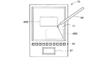
次に、本発明の第3の実施の形態による表示装置について、図面を参照しつつ説明を行う。図7は、本実施の形態による表示装置は、携帯端末装置、例えばPDAである。図7に示すように、本実施の形態によるPDA51は、情報を表示する表示部53と、種々の操作を行う操作ボタン55と、選択を確定する確定ボタン57と、手入力を行うためのスタイラスペン60と、を有している。さらに、本実施の形態によるPDAは、例えば図8にその原理を示すタッチパネル機能を有している。図8に示すアクチィブマトリックス型液晶ディスプレイパネル61は、ガラス基板62、64および偏光板61、65で液晶63を挟んだ構造を有している。また、図8において、符号71、73、75は、それぞれの液晶セルに対応する表示画素電極である。符号80は共通電極である。スタイラスペン60により圧力によって発生する電圧は、偏光板61およびガラス基板62を介して、液晶セルの表示画素電極(ここでは、表示画素電極71、73)に印加される。以上、ペン60により押下圧力を印加する液晶ディスプレイパネル61上の位置に基づいて、表示画面上における座標位置又はこれにより確定される領域を指定することができる。以上のように、公知のタッチパネル機能を用いることで、ペン入力により表示領域などの指定もすることができる。或いは、ペン入力を用いないで操作者が直接指タッチで指定してもよい。
Next, a display device according to a third embodiment of the present invention will be described with reference to the drawings. In FIG. 7, the display device according to the present embodiment is a portable terminal device, for example, a PDA. As shown in FIG. 7, a
図7において、表示部53内のテレビ映像などが表示されている画面内に、ユーザがスタイラスペン60により画定した領域AR1内に、例えば図2に示すEPGなどの文字データを表示させることもできる。このEPG表示に基づいて、視聴したい番組を指定又は予約することができる。尚、この場合、EPGはインターネットによりダウンロードしたデータに基づいて表示させても良い。操作ボタン55と確定ボタン57とを用いて、EPG表示と映像表示とを切り替えて表示させることができるように構成しても良い。或いは、図9に示すように、表示中のEPG画面をスタイラスペンによりドラッグすることで(AR2からAR3)、EPGの表示位置を変更することも可能である。また、スタイラスペン60で画定された領域の、解像度や表示位置、表示対象(映像、EPG)をスタイラスペン操作により切り換えることも可能である。
In FIG. 7, for example, character data such as EPG shown in FIG. 2 can be displayed in the area AR <b> 1 defined by the user with the
以上に説明したように、タッチパネルを用いると、簡単に拡大・縮小表示が可能であるため、素早い操作が可能となる。尚、大きな画面の表示装置においいぇは、必ずしも全画面をタッチパネル領域とする必要はなく、一部の領域内において拡大縮小が可能であっても良い。 As described above, when a touch panel is used, it is possible to easily perform enlargement / reduction display, and thus quick operation is possible. Note that in a large-screen display device, the entire screen does not necessarily have to be a touch panel area, and may be enlarged or reduced in a part of the area.
次に、本発明の第4の実施の形態による表示装置について図面を参照しつつ説明を行う。本実施の形態による表示装置は、表示装置と関連付けされている種々のセンサによるセンシング結果に基づいて、第1の表示画面と第2の表示画面との表示領域又は解像度を変更させる点を特徴とする。図10に示すように、本実施の形態による表示装置は、図7に示すPDA51と同様の構成のPDA71に加えて、表示制御と関連付けされたセンサ73を有している。センサ73は、例えば加速度センサであり、ユーザがPDA71の表示画面75を見ながら移動している場合に、加速度センサ73においてユーザ、すなわちPDA71の移動速度をセンシングする。加速度センサ73においてセンシングした加速度(移動速度に換算できる)に基づいて、表示領域が大きくなるように調整することにより(座標(x0,y0)から(x1,y1)のように、移動中においても文字データ(EPG)を見やすくすることができる。あるいは、例えばPDA71を手に持って振るなどの特定の動作を加速度センサによりセンシングさせて、表示領域を調整することもできる。また、表示領域の変化に応じて解像度も変更されるように制御しても良い。例えばセンサにより検知される変化の度合いと直線(x0,y0)−(x1,y1)の傾きが対応するようにすれば良い。
Next, a display device according to a fourth embodiment of the present invention will be described with reference to the drawings. The display device according to the present embodiment is characterized in that the display area or resolution between the first display screen and the second display screen is changed based on the sensing results of various sensors associated with the display device. To do. As shown in FIG. 10, the display device according to the present embodiment has a
センサとしては、その他、光量センサ(フォトダイオード)、照度センサなども利用できる。例えば光量センサにより周囲が明るいことがわかればEPG表示領域は小さくても見やすいが、光量センサにより周囲が暗いことを検知すると、EPG表示領域を大きくして見やすくするようにすることも可能である。或いは、時計機能を利用して設定されたある時刻になると自動的に表示画面が変更されるようにしても良い。 As the sensor, a light amount sensor (photodiode), an illuminance sensor, and the like can also be used. For example, if the surrounding area is bright by the light amount sensor, it is easy to see even if the EPG display area is small. However, if the surrounding area is dark by the light amount sensor, the EPG display area can be enlarged for easy viewing. Alternatively, the display screen may be automatically changed at a certain time set using the clock function.
次に、本発明の第5の実施の形態による表示装置について図面を参照しつつ説明を行う。本実施の形態による表示装置は、例えば携帯電話機などの通信機能を具備する携帯端末である。図11は、本実施の形態による携帯電話機の正面図である。図11に示すように、本実施の形態による携帯電話機80は、通信機能81(アンテナ及び図示しない無線送受信ユニットで代表させる)と、表示画面83と、操作ボタン82と、表示画面83中において、EPGなどの文字データを表示するための表示領域85の大きさ、表示位置、又は解像度などを変更するための変更ボタン87を有している。この変更ボタンは、例えば、操作の仕方又は操作時間によって変更の度合いを調整できるようになっていても良い。図11の右図は、表示領域の一部領域のEPG表示を表示領域全体に拡大表示させる例を示す図である。
Next, a display device according to a fifth embodiment of the present invention will be described with reference to the drawings. The display device according to the present embodiment is a mobile terminal having a communication function such as a mobile phone. FIG. 11 is a front view of the mobile phone according to the present embodiment. As shown in FIG. 11, the
本実施の形態による携帯電話機によれば、通信機能81により受信した映像データとEPGデータとを表示する際の、表示特性(解像度を含む)を、変更ボタン87により変更することができる。この際、例えば、携帯電話機を把持した方の指のうちの一本のみによって上記変更操作することができるという利点がある。
According to the mobile phone according to the present embodiment, display characteristics (including resolution) when displaying video data and EPG data received by
次に、本発明の第5の実施の形態の第1変形例による携帯電話機について図12を参照しつつ説明を行う。図12は、本実施の形態の第1変形例による携帯電話機であって、携帯電話機の正面図(図12(A))と裏面図(図12(B))とを示した図である。図12(A)、(B)に示すように、本実施の形態の第1変形例による携帯電話機80は、正面側(図12(A))に第1表示画面83が、裏面側(図12(B))に第2表示画面83aが設けられている。携帯電話機80には、図11と同様の構成と機能とを有する変更ボタン87が設けられており、この変更ボタン87を操作することにより、映像表示とEPG表示とを正面側の第1表示画面83と裏面側の第2表示画面83aとのいずれかに択一的に表示させる切り替えを行うことができる。これにより、EPG表示などの文字データ表示の視認性を上げることも可能である。
Next, a mobile phone according to a first modification of the fifth embodiment of the present invention will be described with reference to FIG. FIG. 12 shows a mobile phone according to a first modification of the present embodiment, and shows a front view (FIG. 12A) and a back view (FIG. 12B) of the mobile phone. As shown in FIGS. 12A and 12B, the
次に、本実施の形態の第2変形例による携帯電話機について図13を参照しつつ説明を行う。本変形例による携帯電話機80は、通信機能81の受信状況によってEPG表示領域を変更させることができる調整部86を有している。調整部86は、例えば、新しいEPGデータなどの文字データを検知した際に、文字データの表示が大きくなるように表示の調整を行う。これにより、モニタ情報に基づいて文字データの内容が更新された際に、ユーザに更新された旨とその更新内容とを、表示領域を変更することおよびその表示内容により知らせることができる。連続的に解像度を変更できる操作ボタンを設けても良いし、表示領域の大きさの変化やモニタリングに応じて連続的に解像度が変化するようにしても良い。
Next, a mobile phone according to a second modification of the present embodiment will be described with reference to FIG. The
次に、本発明の第6の実施の形態による表示装置について、図面を参照しつつ説明を行う。図14は図1に対応する図であり、同じ構成については符号を援用する。図14に示すように、本実施の形態による表示装置に設けられた表示制御部1は、メモリコントローラ5に、例えば操作部12の操作又はモニタの検出結果に基づいて変更される表示領域の大きさの変化に対応して、モニタの解像度を自動的に変更する解像度自動変更機構5aを有している。解像度自動変更機構5aは、表示パネルの最大解像度の範囲内において、表示領域の変更に応じて自動的に表示に適した又はそれに近い解像度に変更する。或いは、全体のメモリ中において表示用の表示メモリの量を変更するか又は第1表示と第2表示とに対する表示メモリの割当てを調整するようにしても良い。例えば、EPG表示画面の大きさを4倍(縦横2倍)に変更した場合に、EPG表示領域の解像度を640×480から、1024×768に自動的に変更するか、或いは表示メモリの割当てを通常の32Mbitから128Mbitに変更する。これにより、例えばEPG表示を大きくして見ようとした場合に、解像度又は表示メモリを変更して対応し、見やすい表示を得ることができる。
Next, a display device according to a sixth embodiment of the present invention will be described with reference to the drawings. FIG. 14 is a diagram corresponding to FIG. 1, and reference numerals are used for the same configuration. As illustrated in FIG. 14, the display control unit 1 provided in the display device according to the present embodiment causes the memory controller 5 to change the size of the display area that is changed based on, for example, the operation of the
尚、上記本発明の各実施の形態による表示装置に適用可能な一技術について、図15を参照して以下に説明する。この技術は、出願人が開発してLCフォントという技術であり(特開2001−100725号公報参照)、1つの文字を構成するベクトルデータを基に、文字の滑らかさを損なうことなく大小様々なサイズのフォントを自動生成する技術である。ベクトルデータとして表される文字の交点や端点など、文字を構成するポイントとして重要なポイントを、座標データに置き換えている。これにより、文字データを表示する際に必要なメモリ容量を少なくすることができるとともに、同じメモリ容量で比べると従来よりも鮮明な文字を表示させることができる。さらに、図15に示すように、文字の拡大・縮小操作時には、ポイント間隔を変更(例えば、P1−P2間隔L1を、P1’−P2’間隔L2に変更)することで、必要なメモリ容量の増大を防止することができる。このLCフォント技術を用いると、表示メモリの容量が限られている場合であっても、表示領域の拡大・縮小に応じてポイント間隔を変更することで、鮮明な文字を表示させることができる。 One technique applicable to the display device according to each embodiment of the present invention will be described below with reference to FIG. This technology is an LC font technology developed by the applicant (see Japanese Patent Application Laid-Open No. 2001-100725). Based on vector data constituting one character, the technology can be used in various sizes without sacrificing the smoothness of the character. This technology automatically generates fonts of a size. Points important as points constituting a character, such as intersections and end points of characters represented as vector data, are replaced with coordinate data. As a result, it is possible to reduce the memory capacity required for displaying character data, and it is possible to display characters that are clearer than before when compared with the same memory capacity. Further, as shown in FIG. 15, when the character is enlarged or reduced, the point interval is changed (for example, the P1-P2 interval L1 is changed to the P1′-P2 ′ interval L2). An increase can be prevented. When this LC font technology is used, even if the capacity of the display memory is limited, clear characters can be displayed by changing the point interval according to the enlargement / reduction of the display area.
以上、本発明の各実施の形態について説明したが、本発明は、EPG以外の文字データの表示にも適用可能である。例えば、音楽プレーヤに用いられる楽曲名リストなどのデータ情報や、携帯電話機の住所録、電話番号帳、電子メールの受信データなどが含まれる。 Although the embodiments of the present invention have been described above, the present invention can also be applied to display of character data other than EPG. For example, data information such as a music name list used for a music player, an address book of a mobile phone, a telephone number book, and e-mail received data are included.
本発明による表示装置の対象としては、パーソナルコンピュータや音楽用の携帯型視聴装置などにも適用できる。 The display device according to the present invention can be applied to a personal computer, a portable viewing device for music, and the like.
1…表示制御部、3…フレームバッファ、7…画素密度変換部、11…映像ラインメモリ、15…色空間変換部、17…γ補正ルックアップテーブル(LUT)。 DESCRIPTION OF SYMBOLS 1 ... Display control part, 3 ... Frame buffer, 7 ... Pixel density conversion part, 11 ... Video line memory, 15 ... Color space conversion part, 17 ... Gamma correction look-up table (LUT).
Claims (7)
該表示部の表示に関する制御を行う表示制御部であって、前記表示部における表示特性を変化させる制御を行う表示制御部と、
前記表示部に表示される第1の表示領域の拡大・縮小を操作する操作部とを備え、
前記表示制御部は、前記表示部に表示される前記第1の表示領域の前記操作部からの操作指示による拡大・縮小および/または縦横比の変更に応じて、前記第1の表示領域の表示の解像度を調節し、
前記表示部は、前記第1の表示領域と異なる表示画面に第2の表示領域を表示し、
前記表示制御部は、前記第1の表示領域の表示と前記第2の表示領域の表示の切り替えに応じて、前記第1および第2の表示領域の表示の解像度を調節することを特徴とする表示装置。 A display unit;
A display control unit that performs control related to display of the display unit, the display control unit performing control to change display characteristics in the display unit;
An operation unit for operating enlargement / reduction of the first display area displayed on the display unit,
The display control unit displays the first display area in response to an enlargement / reduction and / or a change in aspect ratio of the first display area displayed on the display unit according to an operation instruction from the operation unit. Adjust the resolution of
The display unit displays a second display area on a display screen different from the first display area;
The display control unit adjusts the display resolution of the first and second display areas in accordance with switching between the display of the first display area and the display of the second display area. Display device.
Priority Applications (1)
| Application Number | Priority Date | Filing Date | Title |
|---|---|---|---|
| JP2004024402A JP4349927B2 (en) | 2004-01-30 | 2004-01-30 | Display device |
Applications Claiming Priority (1)
| Application Number | Priority Date | Filing Date | Title |
|---|---|---|---|
| JP2004024402A JP4349927B2 (en) | 2004-01-30 | 2004-01-30 | Display device |
Publications (2)
| Publication Number | Publication Date |
|---|---|
| JP2005215523A JP2005215523A (en) | 2005-08-11 |
| JP4349927B2 true JP4349927B2 (en) | 2009-10-21 |
Family
ID=34907094
Family Applications (1)
| Application Number | Title | Priority Date | Filing Date |
|---|---|---|---|
| JP2004024402A Expired - Fee Related JP4349927B2 (en) | 2004-01-30 | 2004-01-30 | Display device |
Country Status (1)
| Country | Link |
|---|---|
| JP (1) | JP4349927B2 (en) |
Families Citing this family (3)
| Publication number | Priority date | Publication date | Assignee | Title |
|---|---|---|---|---|
| US8555167B2 (en) * | 2009-03-11 | 2013-10-08 | Sony Corporation | Interactive access to media or other content related to a currently viewed program |
| KR101739406B1 (en) * | 2010-01-08 | 2017-05-24 | 엘지전자 주식회사 | Apparatus for displaying image and method for operating the same |
| US20130021349A1 (en) * | 2010-03-29 | 2013-01-24 | Sharp Kabushiki Kaisha | Display device, liquid crystal module, and image display system |
Family Cites Families (10)
| Publication number | Priority date | Publication date | Assignee | Title |
|---|---|---|---|---|
| JPH07271505A (en) * | 1994-03-29 | 1995-10-20 | Toshiba Corp | Image display controller |
| JPH11196345A (en) * | 1997-10-07 | 1999-07-21 | Masanobu Kujirada | Display system |
| JPH11136595A (en) * | 1997-10-28 | 1999-05-21 | Victor Co Of Japan Ltd | Multi-screen display device |
| JP2000138905A (en) * | 1998-10-31 | 2000-05-16 | Sony Corp | Display device and its method |
| JP4672856B2 (en) * | 2000-12-01 | 2011-04-20 | キヤノン株式会社 | Multi-screen display device and multi-screen display method |
| JP2002232802A (en) * | 2001-01-31 | 2002-08-16 | Mitsubishi Electric Corp | Video display device |
| JP2002300481A (en) * | 2001-03-29 | 2002-10-11 | Sanyo Electric Co Ltd | Digital broadcasting receiver |
| JP2003169125A (en) * | 2001-11-30 | 2003-06-13 | Nec Saitama Ltd | Mobile telephone set |
| JP4192476B2 (en) * | 2002-02-27 | 2008-12-10 | 株式会社日立製作所 | Video conversion apparatus and video conversion method |
| JP2003345320A (en) * | 2002-05-23 | 2003-12-03 | Sony Corp | Device and method for displaying object and broadcasting signal receiver |
-
2004
- 2004-01-30 JP JP2004024402A patent/JP4349927B2/en not_active Expired - Fee Related
Also Published As
| Publication number | Publication date |
|---|---|
| JP2005215523A (en) | 2005-08-11 |
Similar Documents
| Publication | Publication Date | Title |
|---|---|---|
| KR100499845B1 (en) | Active matrix display device and control apparatus thereof | |
| KR102370442B1 (en) | Image display apparatus | |
| KR20030097310A (en) | method and system for adjusting image size of display apparatus and recording media for computer program therefor | |
| RU2656729C2 (en) | Liquid crystal display method and apparatus | |
| US10825420B2 (en) | Image display apparatus | |
| JP2004334058A (en) | Display device and display control method | |
| KR20060123033A (en) | Display system and display apparatus and control method for video source and display apparatus | |
| KR102431503B1 (en) | Image display apparatus | |
| EP3889952A1 (en) | Display device and operating method thereof | |
| KR20200032584A (en) | Image display apparatus | |
| JP4349927B2 (en) | Display device | |
| US10366662B2 (en) | Image display apparatus capable of improving contrast | |
| JP5458524B2 (en) | Mobile device | |
| KR102570381B1 (en) | organic light emitting diode display | |
| US20210264831A1 (en) | Display device and image display method | |
| JP2008209711A (en) | Electronic paper | |
| KR102603620B1 (en) | Image display apparatus | |
| KR101545292B1 (en) | On screen display generator and method thereof | |
| KR20200081174A (en) | Organic light emitting diode display device | |
| KR102287512B1 (en) | Transparent image display apparatus | |
| KR102661825B1 (en) | Signal processing device and image display apparatus including the same | |
| KR100632736B1 (en) | Display Apparatus And Control Method Thereof | |
| WO2022199492A1 (en) | Display device, and image processing method and apparatus | |
| KR100949435B1 (en) | Apparatus and method driving liquid crystal display device | |
| KR20230158762A (en) | Image display apparatus and method thereof |
Legal Events
| Date | Code | Title | Description |
|---|---|---|---|
| A621 | Written request for application examination |
Free format text: JAPANESE INTERMEDIATE CODE: A621 Effective date: 20060125 |
|
| A977 | Report on retrieval |
Free format text: JAPANESE INTERMEDIATE CODE: A971007 Effective date: 20080409 |
|
| A131 | Notification of reasons for refusal |
Free format text: JAPANESE INTERMEDIATE CODE: A131 Effective date: 20080909 |
|
| A521 | Request for written amendment filed |
Free format text: JAPANESE INTERMEDIATE CODE: A523 Effective date: 20081110 |
|
| A02 | Decision of refusal |
Free format text: JAPANESE INTERMEDIATE CODE: A02 Effective date: 20081216 |
|
| A521 | Request for written amendment filed |
Free format text: JAPANESE INTERMEDIATE CODE: A523 Effective date: 20090216 |
|
| A911 | Transfer to examiner for re-examination before appeal (zenchi) |
Free format text: JAPANESE INTERMEDIATE CODE: A911 Effective date: 20090406 |
|
| A131 | Notification of reasons for refusal |
Free format text: JAPANESE INTERMEDIATE CODE: A131 Effective date: 20090616 |
|
| A521 | Request for written amendment filed |
Free format text: JAPANESE INTERMEDIATE CODE: A523 Effective date: 20090622 |
|
| TRDD | Decision of grant or rejection written | ||
| A01 | Written decision to grant a patent or to grant a registration (utility model) |
Free format text: JAPANESE INTERMEDIATE CODE: A01 Effective date: 20090714 |
|
| A01 | Written decision to grant a patent or to grant a registration (utility model) |
Free format text: JAPANESE INTERMEDIATE CODE: A01 |
|
| A61 | First payment of annual fees (during grant procedure) |
Free format text: JAPANESE INTERMEDIATE CODE: A61 Effective date: 20090721 |
|
| FPAY | Renewal fee payment (event date is renewal date of database) |
Free format text: PAYMENT UNTIL: 20120731 Year of fee payment: 3 |
|
| R150 | Certificate of patent or registration of utility model |
Ref document number: 4349927 Country of ref document: JP Free format text: JAPANESE INTERMEDIATE CODE: R150 Free format text: JAPANESE INTERMEDIATE CODE: R150 |
|
| FPAY | Renewal fee payment (event date is renewal date of database) |
Free format text: PAYMENT UNTIL: 20120731 Year of fee payment: 3 |
|
| FPAY | Renewal fee payment (event date is renewal date of database) |
Free format text: PAYMENT UNTIL: 20130731 Year of fee payment: 4 |
|
| LAPS | Cancellation because of no payment of annual fees |