JP4344976B2 - Apparatus, membrane and method for removing organic compounds from biological fluids - Google Patents
Apparatus, membrane and method for removing organic compounds from biological fluids Download PDFInfo
- Publication number
- JP4344976B2 JP4344976B2 JP2000558905A JP2000558905A JP4344976B2 JP 4344976 B2 JP4344976 B2 JP 4344976B2 JP 2000558905 A JP2000558905 A JP 2000558905A JP 2000558905 A JP2000558905 A JP 2000558905A JP 4344976 B2 JP4344976 B2 JP 4344976B2
- Authority
- JP
- Japan
- Prior art keywords
- membrane
- biological fluid
- activated carbon
- polymer
- blood
- Prior art date
- Legal status (The legal status is an assumption and is not a legal conclusion. Google has not performed a legal analysis and makes no representation as to the accuracy of the status listed.)
- Expired - Lifetime
Links
Images


Classifications
-
- B—PERFORMING OPERATIONS; TRANSPORTING
- B01—PHYSICAL OR CHEMICAL PROCESSES OR APPARATUS IN GENERAL
- B01D—SEPARATION
- B01D69/00—Semi-permeable membranes for separation processes or apparatus characterised by their form, structure or properties; Manufacturing processes specially adapted therefor
- B01D69/14—Dynamic membranes
- B01D69/141—Heterogeneous membranes, e.g. containing dispersed material; Mixed matrix membranes
- B01D69/148—Organic/inorganic mixed matrix membranes
-
- A—HUMAN NECESSITIES
- A61—MEDICAL OR VETERINARY SCIENCE; HYGIENE
- A61M—DEVICES FOR INTRODUCING MEDIA INTO, OR ONTO, THE BODY; DEVICES FOR TRANSDUCING BODY MEDIA OR FOR TAKING MEDIA FROM THE BODY; DEVICES FOR PRODUCING OR ENDING SLEEP OR STUPOR
- A61M1/00—Suction or pumping devices for medical purposes; Devices for carrying-off, for treatment of, or for carrying-over, body-liquids; Drainage systems
- A61M1/36—Other treatment of blood in a by-pass of the natural circulatory system, e.g. temperature adaptation, irradiation ; Extra-corporeal blood circuits
- A61M1/3681—Other treatment of blood in a by-pass of the natural circulatory system, e.g. temperature adaptation, irradiation ; Extra-corporeal blood circuits by irradiation
- A61M1/3683—Other treatment of blood in a by-pass of the natural circulatory system, e.g. temperature adaptation, irradiation ; Extra-corporeal blood circuits by irradiation using photoactive agents
- A61M1/3686—Other treatment of blood in a by-pass of the natural circulatory system, e.g. temperature adaptation, irradiation ; Extra-corporeal blood circuits by irradiation using photoactive agents by removing photoactive agents after irradiation
-
- B—PERFORMING OPERATIONS; TRANSPORTING
- B01—PHYSICAL OR CHEMICAL PROCESSES OR APPARATUS IN GENERAL
- B01D—SEPARATION
- B01D63/00—Apparatus in general for separation processes using semi-permeable membranes
- B01D63/08—Flat membrane modules
- B01D63/087—Single membrane modules
-
- B—PERFORMING OPERATIONS; TRANSPORTING
- B01—PHYSICAL OR CHEMICAL PROCESSES OR APPARATUS IN GENERAL
- B01D—SEPARATION
- B01D63/00—Apparatus in general for separation processes using semi-permeable membranes
- B01D63/14—Pleat-type membrane modules
-
- B—PERFORMING OPERATIONS; TRANSPORTING
- B01—PHYSICAL OR CHEMICAL PROCESSES OR APPARATUS IN GENERAL
- B01D—SEPARATION
- B01D65/00—Accessories or auxiliary operations, in general, for separation processes or apparatus using semi-permeable membranes
- B01D65/02—Membrane cleaning or sterilisation ; Membrane regeneration
- B01D65/022—Membrane sterilisation
-
- B—PERFORMING OPERATIONS; TRANSPORTING
- B01—PHYSICAL OR CHEMICAL PROCESSES OR APPARATUS IN GENERAL
- B01D—SEPARATION
- B01D67/00—Processes specially adapted for manufacturing semi-permeable membranes for separation processes or apparatus
- B01D67/0002—Organic membrane manufacture
- B01D67/0009—Organic membrane manufacture by phase separation, sol-gel transition, evaporation or solvent quenching
-
- B—PERFORMING OPERATIONS; TRANSPORTING
- B01—PHYSICAL OR CHEMICAL PROCESSES OR APPARATUS IN GENERAL
- B01D—SEPARATION
- B01D67/00—Processes specially adapted for manufacturing semi-permeable membranes for separation processes or apparatus
- B01D67/0081—After-treatment of organic or inorganic membranes
- B01D67/0086—Mechanical after-treatment
-
- B—PERFORMING OPERATIONS; TRANSPORTING
- B01—PHYSICAL OR CHEMICAL PROCESSES OR APPARATUS IN GENERAL
- B01D—SEPARATION
- B01D69/00—Semi-permeable membranes for separation processes or apparatus characterised by their form, structure or properties; Manufacturing processes specially adapted therefor
- B01D69/02—Semi-permeable membranes for separation processes or apparatus characterised by their form, structure or properties; Manufacturing processes specially adapted therefor characterised by their properties
-
- B—PERFORMING OPERATIONS; TRANSPORTING
- B01—PHYSICAL OR CHEMICAL PROCESSES OR APPARATUS IN GENERAL
- B01D—SEPARATION
- B01D69/00—Semi-permeable membranes for separation processes or apparatus characterised by their form, structure or properties; Manufacturing processes specially adapted therefor
- B01D69/10—Supported membranes; Membrane supports
- B01D69/107—Organic support material
- B01D69/1071—Woven, non-woven or net mesh
-
- B—PERFORMING OPERATIONS; TRANSPORTING
- B01—PHYSICAL OR CHEMICAL PROCESSES OR APPARATUS IN GENERAL
- B01D—SEPARATION
- B01D69/00—Semi-permeable membranes for separation processes or apparatus characterised by their form, structure or properties; Manufacturing processes specially adapted therefor
- B01D69/14—Dynamic membranes
- B01D69/141—Heterogeneous membranes, e.g. containing dispersed material; Mixed matrix membranes
- B01D69/147—Heterogeneous membranes, e.g. containing dispersed material; Mixed matrix membranes containing embedded adsorbents
-
- B—PERFORMING OPERATIONS; TRANSPORTING
- B01—PHYSICAL OR CHEMICAL PROCESSES OR APPARATUS IN GENERAL
- B01D—SEPARATION
- B01D71/00—Semi-permeable membranes for separation processes or apparatus characterised by the material; Manufacturing processes specially adapted therefor
- B01D71/06—Organic material
- B01D71/08—Polysaccharides
- B01D71/12—Cellulose derivatives
- B01D71/14—Esters of organic acids
- B01D71/16—Cellulose acetate
-
- B—PERFORMING OPERATIONS; TRANSPORTING
- B01—PHYSICAL OR CHEMICAL PROCESSES OR APPARATUS IN GENERAL
- B01D—SEPARATION
- B01D71/00—Semi-permeable membranes for separation processes or apparatus characterised by the material; Manufacturing processes specially adapted therefor
- B01D71/06—Organic material
- B01D71/30—Polyalkenyl halides
- B01D71/301—Polyvinylchloride
-
- B—PERFORMING OPERATIONS; TRANSPORTING
- B01—PHYSICAL OR CHEMICAL PROCESSES OR APPARATUS IN GENERAL
- B01D—SEPARATION
- B01D71/00—Semi-permeable membranes for separation processes or apparatus characterised by the material; Manufacturing processes specially adapted therefor
- B01D71/06—Organic material
- B01D71/30—Polyalkenyl halides
- B01D71/32—Polyalkenyl halides containing fluorine atoms
- B01D71/34—Polyvinylidene fluoride
-
- B—PERFORMING OPERATIONS; TRANSPORTING
- B01—PHYSICAL OR CHEMICAL PROCESSES OR APPARATUS IN GENERAL
- B01D—SEPARATION
- B01D71/00—Semi-permeable membranes for separation processes or apparatus characterised by the material; Manufacturing processes specially adapted therefor
- B01D71/06—Organic material
- B01D71/54—Polyureas; Polyurethanes
-
- A—HUMAN NECESSITIES
- A61—MEDICAL OR VETERINARY SCIENCE; HYGIENE
- A61M—DEVICES FOR INTRODUCING MEDIA INTO, OR ONTO, THE BODY; DEVICES FOR TRANSDUCING BODY MEDIA OR FOR TAKING MEDIA FROM THE BODY; DEVICES FOR PRODUCING OR ENDING SLEEP OR STUPOR
- A61M1/00—Suction or pumping devices for medical purposes; Devices for carrying-off, for treatment of, or for carrying-over, body-liquids; Drainage systems
- A61M1/02—Blood transfusion apparatus
-
- B—PERFORMING OPERATIONS; TRANSPORTING
- B01—PHYSICAL OR CHEMICAL PROCESSES OR APPARATUS IN GENERAL
- B01D—SEPARATION
- B01D2321/00—Details relating to membrane cleaning, regeneration, sterilization or to the prevention of fouling
- B01D2321/34—Details relating to membrane cleaning, regeneration, sterilization or to the prevention of fouling by radiation
- B01D2321/346—Details relating to membrane cleaning, regeneration, sterilization or to the prevention of fouling by radiation by gamma radiation
-
- B—PERFORMING OPERATIONS; TRANSPORTING
- B01—PHYSICAL OR CHEMICAL PROCESSES OR APPARATUS IN GENERAL
- B01D—SEPARATION
- B01D2323/00—Details relating to membrane preparation
- B01D2323/42—Details of membrane preparation apparatus
-
- B—PERFORMING OPERATIONS; TRANSPORTING
- B01—PHYSICAL OR CHEMICAL PROCESSES OR APPARATUS IN GENERAL
- B01D—SEPARATION
- B01D2325/00—Details relating to properties of membranes
- B01D2325/38—Hydrophobic membranes
Landscapes
- Chemical & Material Sciences (AREA)
- Chemical Kinetics & Catalysis (AREA)
- Health & Medical Sciences (AREA)
- Dispersion Chemistry (AREA)
- Engineering & Computer Science (AREA)
- Heart & Thoracic Surgery (AREA)
- Manufacturing & Machinery (AREA)
- Inorganic Chemistry (AREA)
- Vascular Medicine (AREA)
- Anesthesiology (AREA)
- Cardiology (AREA)
- Biomedical Technology (AREA)
- Hematology (AREA)
- Life Sciences & Earth Sciences (AREA)
- Animal Behavior & Ethology (AREA)
- General Health & Medical Sciences (AREA)
- Public Health (AREA)
- Veterinary Medicine (AREA)
- Separation Using Semi-Permeable Membranes (AREA)
- External Artificial Organs (AREA)
Description
【0001】
本発明は、複合膜および複合膜を作製するための方法に関する。より詳細には、本発明は、ポリマーマトリックス内に固定化された粒子材料を含む新規な複合膜、およびこのような膜を作製するための方法に関する。このような膜を使用する方法および装置は、病原体不活化処置の一部として、生物学的流体(例えば、血液)に添加された有機化合物を除去するために特に有用である。
【0002】
(発明の背景)
ヒト血液は、細胞成分および非細胞成分の両方を含む。血液中の細胞成分としては、赤血球(RBC)、白血球(WBC)および血小板が挙げられる。血漿は、血液の非細胞成分であり、そして細胞成分が懸濁されている液体媒体である。血漿はまた、種々の他の成分(例えば、タンパク質、血液凝固を補助する化合物(凝固因子)、電解質および代謝産物)を含む。
【0003】
採取中または採取後、ヒト全血は、通常、その種々の細胞成分(RBC、WBC、血小板、血漿)に分離される。典型的には、この分離された成分は、いくらかの期間にわたり保存され得、そして特定の血液成分が必要な患者に輸液され得る。例えば、採取された血漿を患者に輸液して、血漿タンパク質および凝固因子を提供し得るか、または失われた血液容積を置換し得る。血小板は、化学療法および/または放射線処置により血小板を生成する能力が損なわれた癌患者に投与され得る。RBCは、急激な血液損失を経験した患者に、または貧血などを患っている患者における血液の酸素運搬能力を改善するために投与され得る。
【0004】
今や、ウイルス(例えば、B型肝炎ウイルス、C型肝炎ウイルス、ヒト免疫不全症ウイルス(HIV)、ヒトサイトメガロウイルスおよびヒトT細胞リンパ増殖性ウイルス(T−cell lymphotrophic virus)(HTLV))がヒトの血液内および血液成分内に存在し得ることは周知である。特定の細菌(例えば、Yersinia enterocolitica)もまた、ヒトの血液内に存在し得る。血流におけるウイルスおよび/または細菌(本明細書中以降、総称して「病原体」という)の存在は、宿主のみならず、血液を扱う医療従事者にまでも感染および疾患の危険性を引き起こし、そして/または採取血液もしくは血液成分が輸液される場合に、このような血液または血液成分のレシピエントに感染および疾患の危険牲を引き起こす。従って、医療業界は、血液成分に見出される病原体を除去または不活化させるための方法および装置を開発することにより、このような病原体を含む血液を輸液するという危険性を低減することを試みてきた。本明細書中で使用される場合「病原体不活化(およびその変化形(form))」は、一般に、病原体を生存生物に対して無害にすることを意味する。病原体不活化としては、病原体(ウイルスまたは細菌いずれでも)の殺傷、破壊、もしくは根絶、または病原体が複製する能力を直接的もしくは間接的いずれかで阻害することが挙げられる。「病原体を不活化する化合物」とは、病原体不活化(このような化合物の分解産物を含む)において使用される化合物をいう。
【0005】
血液からウイルスを除去するという1つの初期の試みは、例えば、白血球細胞中に混入した細胞内ウイルスを除去するための血液および血液成分の濾過を含んだ(Rawalら「Reduction of Human Immunodeficiency Virus−Infected Cells From Donor Blood by Leukocyte Filtration」Transfusion、第460−462頁(1989))。
【0006】
ウイルス、および特に血液中の細胞外ウイルスを不活化するための他の先行方法としては、血漿の蒸気滅菌、血液または血液成分から病原体を浄化するために「界面活性剤」の使用が挙げられる。
【0007】
光化学薬剤および光で血液または血液成分を処理することによる病原体不活化(光活性化といわれる)がまた、考えられた。適切な波長の光により活性化される場合、この光化学薬剤は、ウイルスを直接殺傷するか、またはウイルスが複製する能力を間接的に阻害するかのいずれかである。従って、いずれかの場合にウイルスを「不活化」する。以下を含むいくつかの公知の光化学薬剤は、血液中のウイルスを不活化させることにおける使用のために使用されるか、または開示された:ソラレン(米国特許第5,459,030号に記載される)、フタロシアニン(pthalocyanine)(例えば、Rywkin,S.ら、Photochem.Photobiol.60:165−170(1994));ならびにトルイジンブルーO、アズールA、アズールB、アズールC、チオニン、メチレンブルーおよびジメチルメチレンブルーが挙げられるが、これらに限定されないフェノチアジン色素。例えば、米国特許第5,527,704号(本明細書中に参考として援用される)は、生物学的流体中のウイルスを不活化するための方法および装置を開示する。ここで、生物学的流体(例えば、血漿)がメチレンブルーと合わされ、そして一定期間にわたりメチレンブルーを活性化するに適切な強度および波長の光に供される。
【0008】
生物学的流体(血液または血液成分)を処置するための、光活性化を含まない他の方法もまた、公知である。例えば、国際公開番号WO98/070674が、アジリジンに結合させたマスタードを記載する。米国特許第5,691,132号および同第5,559,250号(これらは、本明細書中に参考として援用される)は、RBCと、核酸結合リガンドおよびマスタード基を有する化合物とを接触させることにより、RBCを含む生物学的流体を処置するための方法を記載する。このような成分は、病原体(ウイルスおよび細菌の両方)の核酸と反応して、この病原体の複製を阻害する共有結合複合体を形成すると考えられる。アクリジン化合物の例としては、例えば、N1,N1−ビス(2−クロルエチル)−N4−(6−クロロ−2−メトキシ−9−アクリジニル)−1,4ペンタンジアミンが挙げられるがこれらに限定されない。
【0009】
病原体不活化化合物の潜在的な副作用を低減または「終息させる(quench)」ことにより病原体不活化化合物の有効性を増強するために、上記の処置系において特定の他の有機化合物を含むことがまた所望され得る。例えば、特定の天然に存在するトリペプチド(限定されないが、例えば、還元L−グルタチオン)を含めることは、潜在的な副作用を終息させ、そして病原体不活化化合物による最大の病原体不活化を可能にする。病原体不活化プロセスにおいて有用なクエンチャーの他の例としては、メルカプトエタノールのようなスルフヒドリル(Rywkin,S.ら、Transfusion 35:414−20(1995)に記載される)、システイン、クエルセチン(Ben−Hurら、Photochem.Photobiol 57:984−8(1993)に記載される)およびルチン(Margolis−Nunno、Transfusion 35:852−862(1995)に記載される)が挙げられ得る。
【0010】
今日までに知られている病原体不活化方法の多くが、(1)血液中に通常は存在しない化合物(例えば、光化学色素、マスタード基を有する核酸結合剤)または(2)ヒト血液中で見られる代表的な濃度より過剰な濃度の化合物(例えば、L−グルタチオン)のいずれかの添加を含む場合、患者もしくは他のレシピエントに輸液する前に、処置した生物学的流体からできるだけ多くの添加化合物を実質的に除去することが望ましい。
【0011】
例えば、病原体不活化において使用される光活性化薬剤を分離するための方法および装置が米国特許第5,660,731号に記載される。その特許においては、メチレンブルーのような光化学薬剤は、この光化学薬剤と、例えば、活性化炭素繊維を含む多孔性媒体とを接触させることにより血液から分離される。この多孔性媒体は、ウェブ状、シート状、円筒状の形態にあり得るか、または生物学的流体が通過し、従ってこの多孔性媒体と接触する、入り口および出口を備えるフィルターに備えられ得る。
【0012】
同様のアプローチが米国特許第5,639,376号に記載され、これは、白血球およびメチレンブルーのようなウイルス不活化剤、その代謝産物ならびに光分解産物を、血漿または他の血液画分から除去するフィルターを開示する。米国特許第5,660,731号におけるように、抗ウイルス薬剤の除去は、血液と、例えば、白血球および抗ウイルス薬剤の両方の除去に適合したフィルターとを接触させることにより達成される。このフィルターは、メチレンブルーのための吸着剤としての活性炭が挙げられる。
【0013】
米国特許第4,728,432号は、より一般には、血液中に含まれる毒性物質を吸着により除去するための方法およびデバイスを記載する。そのような特許において記載される吸着剤は、例えば、支持体部材に固定された活性炭を含む。この活性炭は、ポリマーと結合している。
【0014】
有機化合物を生物学的流体から除去するための方法およびデバイスの他の例は、「Methods and Devices for the Reduction of Small Organic Compounds from Blood Products」と題される米国特許出願第09/003,113号(本明細書中に参考として援用される)に記載される。その出願は、例えば、血液製剤中のアクリジン、アクリジン誘導体、メチレンブルーまたはチオールの除去のために、支持体に適用される活性炭ビーズのような吸着剤粒子を使用することを記載する。活性炭ビーズは、パウチもしくは上包装内に含まれ得るか、繊維化したマトリックス内に捕捉され得るか、または、繊維化したマトリックス内に捕捉され得かつパウチもしくは上包装内に含まれ得る。
【0015】
(発明の要旨)
本発明は、医療分野において、より詳細には、病原体不活性化の分野において特定の適用を見出し得る。したがって、本発明は、生物学的流体内の選択された有機化合物の濃度を低減する装置に関する。本発明の一つの局面では、この装置は、生体適合性の容器およびこの容器の内部に配置された膜を含む。この膜は、選択された量の繊維化されていないポリマー材料および選択された量の吸着材料を含む。
【0016】
本発明はまた、生物学的流体中の選択された有機化合部を除去するための方法に関する。本発明の一つの局面では、この方法は、選択された有機化合物を含むある量の生物学的流体を提供する工程を包含し得る。この方法はさらに、生物学的流体を膜(これは、選択された量の繊維化されていないポリマー材料およびこのポリマー材料内に固定化された選択された量の吸着材料を含む)と接触させる工程を包含する。
【0017】
本発明はまた、生物学的流体内の選択された有機化合物の濃度を低減させるための可撓性の複合膜に関する。この膜は、選択された量のポリマー材料および選択された量の活性炭を含む。この活性炭は、ポリマーマトリックス内に実質的に固定化されている。この膜は、膜の外側表面上に選択的に透過性のスキンを含む。
【0018】
(図面の詳細な説明)
ここで図面を参照すると、本発明は、病原体不活化化合物(病原体不活化プロセスにおいて使用される病原体不活化薬剤、それらの副生成物および/または他の添加される有機化合物を含む)の除去に関連して、例示のみの目的で示される。以下により十分に記載されるように、本発明の特定の局面(例えば、膜および膜を作製するための方法)は、生物学的生成物の病原体不活化の分野を越えた適用を有する。例えば、膜およびこの膜を作製する方法は、粒子材料がポリマーマトリックスによりまたはポリマーマトリックス内に固定化された装置(例えば、膜、チューブ、ロッドなど)を有することが所望される、任意の他の分野および産業における適用を有し得る。従って、本発明の詳細な説明は、一般に、生物学的流体(例えば、血液成分)の病原体不活化の状況にあるが、本発明の範囲は、添付の特許請求の範囲に記載される。
【0019】
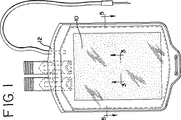
図1は、生物学的流体(例えば、血液および血液成分(これらに限定されない))を保持するに適切なプラスチック容器12の内部に本発明に従って作製された膜10を示す。図1に示すように、膜10は、平坦なシート形状、あるいは、図2および6に示されるようにひだ付き形状、または図13に示されるように波型形状にあり得る。ひだ付け加工シートまたは波型シートは、膜表面と除去される化合物との接触を増大させる。図1および2に具体的に示される膜10は、容器内部の断面積の大部分を占有するが、この膜シートのサイズおよび寸法が本発明の範囲から逸脱することなく変更され得ることは理解されるべきである。また、本発明は、シート状膜(平坦、ひだ付きまたは波型)に限定されず、繊維、ロッド、チューブなどのような他の形態にも具体化され得ることが理解される。また、本発明に従って作製される膜は、フロー入口およびフロー出口を有するデバイス中に収納され得る。このデバイスは、流体のフローが膜表面に対して横切る実質的に平坦な膜を備え得るか、あるいは波型またはひだ付き膜を備え得、それによって波形間またはひだ間の領域に流体の軸方向のフローのためのフローチャネルを提供する。
【0020】
容器の議論を簡単に参照すると、容器12は、生物医学的容器を作製するために典型的に使用される任意のポリマー材料から作製され得る。例えば、この容器は、可塑剤(例えば、DEHP、TEHTM、クエン酸エステルまたは他の公知の生体適合性可塑剤)を用いて可塑化されたポリ塩化ビニル(PVC)から作製され得る。あるいは、この容器は、可塑剤ありまたはなしのポリオレフィンのような非PVCプラスチックから作製され得る。生物学的流体を貯蔵するために適切な生体適合性容器の例としては、米国特許第5,167,657号、同第5,100,401号、および同第5,026,347号に記載される容器が挙げられる。
【0021】
ここで膜10の説明に戻ると、概して図3および4に示されるように、膜10は、この膜のポリマーマトリックス16内のポリマー材料と粒子材料(拡大されて(as specs)示される)との複合物である。膜10は、必要に応じて、支持体18を含んでいてもよいし(図3)、支持体なしで作製されていてもよい(図4)。図3に示されるように、例えば、支持体18は、膜10のコアを形成し、そしてこの膜の連続マトリックス16内の実質的開放構造(open structure)を提供する。膜10の外表面は、「スキン」19をさらに備え得る(以下により詳細に記載される)。図3および図18に示されるように、スキン19は、ランダムに間隔を空けた表面孔21を備え得る。
【0022】
別の代替において、例えば、図7に示されるように、この膜10は、容器壁12の内部によって直接支持され得る(すなわち、容器壁が支持体として働く)。なお別の代替において、膜10の縁部は、図7Aに示されるように、容器12のシールされた壁13により保持され得る。
【0023】
支持体18は、ポリマー材料がそこに接着する任意の材料から作製され得、これらの材料としては、例えば、ポリマー、ガラス、布地(cloth)、または他の繊維性材料(例えば、図3に示され、ここでは、繊維18aが認められ得る)が挙げられる。1つの実施態様において、この支持体は、ポリエステルメッシュ材料であり得る。このような材料は、Mount Holly Springs,PAのAhlstrom Corp.からのHollytex 3257として入手可能である。
【0024】
上記のように、膜10は、ポリマー材料(例えば、ポリマーまたはコポリマー)およびポリマー材料内に固定化された、選択された量の粒子材料から作製され得る。このポリマー材料は、ポリマー(エラストマーを含む)、コポリマー、ポリマーの混合物、コポリマーの混合物、またはポリマーとコポリマーとの混合物であり得る。膜10が、生物学的流体とともに使用される場合、このポリマー材料は、これが接触する生物学的流体に悪影響を与えないべきである。ポリマー材料はまた、粒子材料と実質的に混和性であるべきである。典型的には、このポリマー材料は、親水性であり得るが、親水化され得る疎水性ポリマー材料でもあり得る。本発明の膜における使用のために適切なポリマー材料の例としては、以下が挙げられるが、それらに限定されない:ポリウレタン、酢酸セルロース、ポリビニリデンフルオリド(PVDF)、ポリ塩化ビニル(PVC)、熱可塑性エラストマー(例えば、Hytrelの名称で販売されているもの)およびエチレンビニルアルコールコポリマー。本出願において特に有用なのは、ポリウレタンである。ポリウレタンは、種々の供給元(例えば、Morton International Inc.)から入手可能である。ポリウレタンであるMorthane PNO3およびMorthane PB355が現在のところ好ましい。
【0025】
同様に、粒子材料は、選択されたポリマーと合わせられ得るべきである。膜10を使用して、選択された有機化合物を生物学的流体から吸収する場合、粒子材料が吸着剤であり得る。この膜がより滑らかな表面を有し、従ってそれが接触する流体およびその中の成分に対して荒くないように、粉末化形態における吸着剤が好ましくあり得る(例えば、ビーズまたは他のより大きな粒子よりも)。さらに、粉末化吸着剤は、ポリマーによって、より効率的に固定化され得る。もちろん、吸着剤の選択はまた、特定の吸着剤に対する、除去される化合物の親和性に一部依存し得る。
【0026】
活性炭は、吸着剤として公知であり、そして本発明のために好ましい吸着剤である。活性炭は、ビーズ形態で入手可能であるが、上記の理由のために、粉末化活性炭が好適であり得る。活性炭はまた、種々の供給源から入手可能である。活性炭の例としては、Marshall,TexasのNorit(登録商標)Americas Inc.から入手可能な活性炭粉末(例えば、Norit Pac 200、Darco S51FF、Darco KB−B、Norit SX Ultra、G−60 Norit(登録商標)A Supra、Norit(登録商標)B SupraおよびNorit E(登録商標) Supra)が挙げられる。典型的には、活性炭粒子は多孔性であり、そして約20μ未満または10μ未満ですらある直径を有し、そして約1000m2/gを超える総表面積を有する。本出願の膜を作製するにおいて特に有用なのは、Norit(登録商標) A Supra活性炭粉末である。例えば、Norit(登録商標) A Supraにおいて、この粒子の大部分が、約20μ未満の直径を有し、そしてかなりの数が約10μ未満の直径を有する。Norit(登録商標) A Supraは、約2000m2/gの典型的な総表面積を有する。もちろん、他の活性炭もまた使用され得る。本発明における使用のために適切な粒子材料の他の例としては、細孔性ポリスチレン吸着剤ビーズが挙げられ、このビーズは、好ましくは、約20μm以下の直径を有するより小さな粒子を提供するように粉砕され得る。
【0027】
以下でより詳細に議論されるように、上記のポリマー材料および粒子材料を合わせて、膜10を作製するために使用されるスラリー様ブレンドを形成する。このブレンドは、(1)溶媒中に溶解されたポリマー材料から誘導されるポリマー溶液および(2)粒子を含む。あるいは、このブレンドは、溶融ポリマー(すなわち、溶媒なし)および粒子を含み得る。本明細書中で使用される場合、「ブレンド」とは、ポリマー材料(ポリマー溶液または溶融ポリマーのいずれかとして)および粒子材料をいう。本発明に従い、ブレンド中の固体の量(すなわち、溶媒を除く)は、概して、約40重量%〜90重量%の間の粒子材料、および約10重量%〜60重量%の間のポリマー材料を含むことが望ましい。1つの実施態様において、ブレンド中の粒子の量(重量で)は、(固体の)50%を超えるべきである。好ましくは、ブレンド中の固体は、約70%の粒子材料、および約30%のポリマー材料を含み得る。
【0028】
上記の型の膜(および、特にポリマー溶液と粒子とのブレンドから誘導されるもの)は、例えば、概して図8に記載される装置20を使用する、支持体18上でこのブレンドをフローキャストまたは押し出し成形することにより作製され得る。図8に示されるように、装置20は、支持体18のロールシートを備え得る。支持体は、支持体シートおよびブレンドを受け入れるV字型チャンバー24へ(ディスペンサー22から)配置される。このブレンドは、チャンバー内の支持体18の外表面に塗布される(図9に示すように)。その上にブレンドが塗布されている支持体は、チャンバー24の底部の開口部からチャンバーの外に出る。もちろん、本発明の膜はまた、例えば、ブレンドをドラムに塗布した後にドラムの表面からこの膜を剥がすこと(そして以下に記載のようにこの膜をさらに加工すること)により一体化した支持体なしで作製され得る。いずれにしても、膜10が、支持体ありで作製されも、支持体なしで作製されても、装置20は、この膜を作製するプロセスにおいて使用される溶液を含む1つ以上の浴26および28を備え得る。装置20はまた、乾燥オーブン30を備え得る。必要に応じて、装置20は、さらなる浴32およびオーブン34を、膜10のさらなる乾燥後処理のために備え得る。典型的には、装置20は、概して図8において示されるように、膜が上に縫うように進められる一連のローラー36を備える。ローラー36の回転は、ディスペンサー22から一連の浴26、28、32ならびにオーブン30および34を縫うように進む膜の移動をもたらす。最終的に、所望であれば、巻き取りのための装置38および膜10のその所望の幅への切断のための装置もまた備えられ得る。
【0029】
本発明の膜を作製するための1つの方法に従って、このポリマー材料および粒子材料は、概して上記に記載の比率で合わせられる。具体的には、ポリマー材料は、最初に適切な溶媒中に溶解され得る。異なるポリマー材料のための種々の溶媒が使用され得る。例示目的のみのために、ポリマーがポリウレタンまたは酢酸セルロースである場合、適切な溶媒は、N−メチルピロリドン(NMP)であり得る。PVCに適切な溶媒は、テトラヒドロフランであり得る一方で、PVDFに適切な溶媒は、ジメチルアセトアミド(DMAC)であり得る。もちろん、他の溶媒もまた使用され得ることは当業者に理解される。
【0030】
次いで、選択された量の粒子材料を、溶解されたポリマー材料(ポリマー溶液)に添加して、スラリー様ブレンドを提供し得る。次いで、このブレンドは、支持体18が縫うように進められたチャンバー24に導入される。図9および10により詳細に示されるように、チャンバー24は、ほぼV字型であり、底部に間隙40を備え、これを通って支持体18が外に出る。間隙40の幅は、支持体18の種々の厚さに適合し、かつまた部分的には支持体18上にコーティングされるブレンドの厚さを制御するように調節され得る。
【0031】
図10に示されるように、チャンバー24の下部は、下向きに延びる壁(またはランド)43によって規定される狭い通路41を備える。ブレンドが通路41を流れるとき、壁43と支持体18との間に生じる剪断力は、壁43から離して膜の中心へとブレンド内の粒子を進め得る。従って、現在では、多くの粒子が外表面またはその付近より膜の内部に分布され得、従って(例えば、概して図3および4に示されるように)、膜(およびより詳細にはポリマーマトリックス)の内部の上に「スキン」部分を有する膜を提供すると考えられる。スキン中もしくはその付近より膜の内部内に多くの粒子が配置されるので、粒子が膜から外れ、そして膜10が使用の間に接触している流体中に入ってしまうことはあまりないようである。例えば、約20μmを超える直径を有するより大きな粒子が通路41に入ることを妨げられ、従って、膜内に含まれないともまた考えられる。このことは、より大きな粒子がポリマーマトリックスにより、またはその内部に効率的に固定化されないかもしれないという観点から望ましくあり得る。従って、より大きな粒子を排除することは、粒子がポリマーから外れ、そして膜10が使用の間に接触している液体に入ってしまうという可能性を低減させる。
【0032】
さらに、壁43はまた、確実に支持体18が間隙40内で適切に中心合わせされることにより、支持体18の両方の側面上のブレンドの厚さが対称的かつ均質であることを示すことを補助し得る。支持体18が間隙40内に適切に中心合わせされなければ、通路41内の支持体の両方の側面に対する剪断力は等しくない。支持体18の一方の面に対する圧力がより大きいことにより、支持体が位置を変えて間隙40の中央に返ってき得る。従って、本発明の装置は、ブレンドの均質なコーティングを受ける「セルフセンタリング」膜を提供する。1つの実施態様において、通路の長さ(壁43により規定される)は0.5〜3cmの間の長さであり得る。
【0033】
本発明の代替実施態様において、第2のV字型チャンバー(図8においてチャンバー25として破線で示される)を用いて、(例えば、保護コーティングを提供するように、そして膜の表面付近の粒子材料が外れることをさらに防止するように)この膜に対してさらなるポリマー材料を塗布し得る。この第2のチャンバーは、チャンバー24を出てすぐに、ブレンドが塗布された支持体が、第2のチャンバー25に入るように、チャンバー24と連続して、かつその下に配置され得る。第2のチャンバーは、例えば、異なるポリマー材料またはブレンドを作製するために使用されるより希釈された濃度のポリマー材料(これは、より低濃度の粒子材料を含んでもよく、または全く粒子材料を含まなくてもよい)を含み得る。
【0034】
図9および10に示されるように、このブレンドは、支持体18の両側面に塗布され得る。しかし、必要に応じて支持体18の一方の側面のみがこのブレンドでコーティングされてもよいことが理解される。いずれにしても、コーティングされた支持体は、第1の凝固浴26に誘導される。典型的には、第1の凝固浴26において、このブレンドは、ポリマー溶液のポリマー部分に対しては非溶媒であるが、ポリマー溶液の溶媒部分とは自由に混和性である液体または溶液と接触される。この液体または溶液との接触により、固体(ポリマーおよび粒子)を凝固させ、そして浴26を出てすぐに、ポリマー材料/粒子ブレンドが2つの連続するが分離している相を備えるように、液体部分を交換する。一方の相は、包埋粒子を有するポリマー材料を含有し、そして他の相は、非溶媒液体を含有する。
【0035】
ローラー36の回転は、凝固浴26から1つ以上の抽出浴28へと、膜10を前進させる。典型的には、抽出浴28は、ポリマーを溶解するために使用される残りの任意の溶媒を膜から抽出する溶液を含む。溶媒の型および強度に依存して、膜は、一連の洗浄工程を受け得、各浴は、さらに膜を洗浄して溶媒を除去する。例示のみの目的で、3つの抽出浴28を図8に示す。
【0036】
一旦溶媒が膜から実質的に抽出されると、この膜は乾燥され得る。図8に示されるように、最後の抽出浴の後に、膜はオーブン30(例えば、空気循環オーブン)へと導入され得る。もちろん、他の形態の乾燥工程もまた、使用され得、それらとしては、風乾工程または加熱表面に膜を接触させる工程が挙げられる。
【0037】
乾燥前または乾燥後に、膜10は、例えば、膜10を親水性にするために、(乾燥工程の結果としての)湿潤性の喪失を防ぐために、または乾燥工程の結果として喪失または低減されているかもしれない膜の湿潤性を回復するために、界面活性剤または他の薬剤でさらに処理され得る。従って、図8に示されるように、この膜は、湿潤剤もしくは親水化コーティング剤(hydrophilizing coating agent)を含む別の浴32に導入され得る。界面活性剤を塗布する方法は、浴32中でこの界面活性剤を浸す工程に限定はされないが、噴霧工程、または他の形態の、膜に界面活性剤を塗布する工程も含まれ得る。処理剤で処理されると、オーブン34でのさらなる乾燥工程が所望され得る。次いで、この膜は、(その所望の幅に)切断され得、そして装置38に巻き取られ得る。膜10は、容器12に収容するためのより小さな長さにさらに切断され得る。切断された膜10の縁部は、エポキシまたは他のシーラントで封入されてもよいし、処理されてもよい。
【0038】
上記のように、膜は、さらに外形をつけられて、ひだ付きシートまたは波型シートにされ得る。波型膜を形成する装置44は図11〜12に示され、そして得られた膜10は図13に示される。図11〜12に示されるように、装置44は一連の積み重ねられたロッド46を備え得、ロッドの端は支持部材50のスロット48内に保持される。膜10は、図12に実質的に示されるように、ロッド44間を織るように進められる。装置44は、織り込まれた膜10と共に、約10〜30分間、そのポリマーに適切な温度にてヒートセットされる。例えば、ポリマーがポリウレタンである場合、代表的な温度は約100℃であり得、そして代表的な加熱時間は約15分であり得る。加熱後、膜は図13に示すような波型の形状を保持する。当然のことながら、膜に外形をつける(すなわち、波型にする、ひだをつける)他の方法もまた、本発明を逸脱することなく可能であることが理解される。次いで、仕上がった膜10は、例えば、γ線照射により滅菌され得る。
【0039】
特定の実施態様において、膜10はポリウレタンおよび活性炭粉から作製される。例えば、ポリウレタンはN−メチルピロリドン(NMP)のような溶媒に溶解される。ほぼ5重量%〜20重量%の間のポリマーは、このポリマーを溶解するために、約80重量%〜95重量%の溶媒と合わせられ得る。好ましくは、ポリマーがポリウレタンである場合、ポリマーの量は、総ポリマー/溶媒重量の約6%〜15%の間である。本明細書において使用する場合、ポリマー溶液は、溶媒中のポリマーの百分率(重量%)として表される。したがって、例えば、10グラムのポリウレタンは、90グラムのNMPと合わせられて、10%のポリマー溶液を提供し得る。次いで、得られたポリマー溶液は、粒子材料と合わせられてブレンドを形成する。
【0040】
本明細書において使用される場合、ブレンドの組成は、粒子およびポリマー(固体)の合わせた量における粒子材料(例えば、活性炭)の重量百分率として表現される。したがって、例えば、10グラムのポリマーおよび90グラムの溶媒を含むポリマー溶液に添加された10グラムの活性炭(または他の粒子)は、50%の活性炭および50%のポリマーを有する膜を提供する。同様に、10グラムのポリマー(ポリウレタン)を有するポリマー溶液に添加された30グラムの活性炭(粒子)は、75%「荷重(loading)」の活性炭(または他の粒子)および25%のポリウレタンを有する膜を生じる(すなわち、ポリマーおよび粒子(40(10+30)グラム)中の30グラムの粒子は、75%荷重の粒子である)。いずれにせよ、活性炭の量は、少なくとも10重量%、好ましくは70重量%であるべきである。
【0041】
活性炭をポリマー溶液とブレンド後、そのブレンドは、次いで、上記のようにチャンバー24中に導入され、そしてディスペンサーロール22から供給されるポリエステルメッシュ材料に適用され得る。好ましい実施態様において、このブレンドは、図9および10に示されるように、ポリエステル支持体の両側に適用されて、250マイクロメートルと1000マイクロメートルとのほぼ間、そして好ましくは400〜1000マイクロメートル、の総膜厚(フィルムおよび支持体)44を達成する。ほぼ400〜1000マイクロメートルの膜厚を達成するために、チャンバー24中の間隙40は、その膜の所望の厚さより僅かに広くあるべきであり、そして例えば、約600マイクロメートル〜1200マイクロメートルの間の寸法であり得ることが観察された。より詳細には、70%活性炭粉末を含み、約500μmの厚さを有するポリウレタン膜を提供するためには、間隙40は約705μmであるべきであり、そして70%活性炭粉末を含み、1000μmの厚さを有するポリウレタン膜を提供するためには、間隙40は約1105μmであるべきことが観察された。次いで、膜10は凝固浴26中に導入され、上記のポリウレタン/活性炭ブレンドの場合には、この凝固浴は水のみを含み得る。現在理解されるように、このブレンドを水に曝すことにより、そのポリマーブレンドの凝固が引き起こされる(なぜなら、ポリウレタンは水と混和性でないからである)。ポリマーの凝固が進むにつれて、溶媒NMPは、水と交換されてそのポリマーから去る。膜が、連続的に、一連の抽出浴28に導入され、そしてそれらの浴から取り出されるにつれて、膜からの溶媒のさらなる除去が生じる。
【0042】
凝固浴26、抽出浴28ならびにオーブン30および34を通過する膜10の移動速度は、ローラー30の回転速度を調整することによって、(例えば、ヒトオペレーターにより)制御され得る。例えば、膜が10%ポリウレタン溶液中の70%活性炭を含む1つの実施態様において、膜は、1ft/分〜4ft/分のほぼ間で、代表的には1ft/分で、凝固浴、抽出浴、および乾燥オーブンを通って進む。このことにより、例えば、溶媒(NMP)が膜から実質的に抽出され、好ましい範囲内の膜厚を生じ、十分な乾燥を提供することが確実となり、そして膜が界面活性剤で十分に処理される(そのような処理が所望であれば)ことが確実となる。当然のことながら、ポリウレタン以外のポリマーについて、凝固/抽出のための異なる溶液、凝固浴および抽出浴における膜の滞留時間を短くするかまたは長くするかのいずれかのための異なるライン速度が所望され得るかまたは要求さえされ得る。例えば、ポリマーがPVDFである場合、凝固浴はメタノールを含み得る。
【0043】
NMP溶媒の抽出後、膜10は、オーブン30において、10分と30分との間の任意の時間、少なくとも40℃、代表的には50℃の温度にて乾燥され得る。
【0044】
膜10は、浴32において、湿潤剤または親水性化コーティング剤(以下「処理剤」)で処理されて、膜10の吸着特性を増強し得るか、乾燥後の湿潤性の損失を予防し得るか、または乾燥により引き起こされる膜の喪失もしくは減少した湿潤性を回復し得る。処理剤は、膜10を親水性化し得る化合物(適切な溶媒に溶解された)であり得る。例えば、処理剤は、イソプロピルアルコール/水溶液中に溶解したポリビニルアルコール(PVOH)であり得る。詳細には、ポリマーがポリウレタンと活性炭とから作製される場合、親水性化浴は、約50/50の水/イソプロピルアルコール溶液中に約0.20%〜約1.5%の間のPVOHを含み得る。ポリウレタンおよび活性炭から作製される膜については、0.25%〜約1%までのPVOH溶液が好ましくあり得る。
【0045】
他の溶液もまた、膜10を処理し、そして膜をより親水性にするために使用され得る。詳細には、塩化ナトリウムを含む溶液が適切であり、これには、0.45%NaClまたは0.9%NaClを含む溶液が挙げられる。これは、例えば、赤血球の貯蔵に一般に使用される溶液(例えば、Adsol(登録商標);本明細書中に参考として援用される米国特許第4,267,269号に記載される)を含み得る。膜を処理するために使用され得るなお他の溶液は、イソプロピルアルコール、ポリエチレンオキシド(PEO)および/または70/30、50/50、30/70のイソプロピルアルコール/水溶液中のPEOおよびポリウレタンのブレンド中1〜10%グリセロールを含む。膜が生物学的流体(例えば、血液)と使用される場合、膜10はまた、特定の化合物または生物学的成分に関して膜の血液適合性をさらに向上させる薬剤で処理され得る。1つのそのような薬剤は、ポリヒドロキシエチルメタクリレートまたはpHEMAである。いずれにせよ、膜10は、乾燥の前または後に上記の溶液で処理され得る。
【0046】
本発明に従って作製された膜は、代表的には取り扱いが困難であり、かつ流失(shedding)し易い微細粒子粉末を固定化する、独特で費用効率の高い方法を提供する。これは、外来粒子を血液中または他の生物学的流体中に導入することが望ましくないと考えられる場合の血液治療の分野において特に有利である。本発明に従って作製された膜はまた、ある程度、独特である。なぜならば、粒子が、病原体不活化処置において使用される有機化合物のための吸着剤として作用する粉末の能力を弱めることなく、ポリマーマトリックスにより実質的に捕捉されるからである。今や理解されるように、微細粉末は、ポリマーマトリックスにわたって広く分散され、したがって有機化合物の分子のための多くの吸着部位を提供する。この粉末の広範な分散はまた、有機化合物の分子が吸着剤粉末によって捕捉される前に移動しなければならない距離が、より短いことをも意味し得る。
【0047】
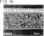
本発明に従って作製された実際の膜は図14〜20に示される。詳細には、図14〜20は、10%ポリウレタン溶液(PNO3)に由来するブレンドから作製された膜を示す。10%ウレタン溶液に、Norit(登録商標)A Supra活性炭粉末が添加され、約70%の炭荷重を得る(すなわち、この固体は70%の活性炭および30%のポリウレタンを含む)。膜を、図8(単一チャンバー24を使用する)に一般的に示され、そして本明細書に記載される装置を使用して調製した。ポリエステルメッシュを支持体として使用した。
【0048】
得られた膜は、図14中でスポンジ様構造の列として見えるポリマーマトリックスを含む。図14にさらにみられるように、このポリマーマトリックスは、ポリエステルメッシュ支持体の部分を横切ってさえ、膜全体に実質的に連続する。ポリエステルメッシュ支持体は、断面において、膜の中心近くの大きい方の円または楕円構造としてみられる。ポリマーマトリックスの上面および下面は、薄い「スキン」層を含む。図15〜17に見られるように、半球の粒状体が、ポリマーマトリックス内に固定化された活性炭の粒子であり得ると考えられる。
【0049】
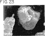
図18は、膜の表面およびより詳細にはスキンの写真である。図18および19に見られるように、スキンは、完全には連続しておらず、膜を横切ってランダムに間隔を置いて配置された空隙を含む。拡大すると、膜の表面近くのポリマー物質により保持された炭粒子が見られ得る(図19および20)。図20において見られるように、ポリマー物質でコートされた活性炭粒子は、活性炭粒子単独の写真では見られない(図23〜25)、織られたような外見を有する。ポリマーマトリックスのスキン層は、粒子がはずれることの予防を補助すると考えられる。重要なことは、この保護機能を提供しながら、スキン層は、質量輸送を妨げず、除去されるべき有機化合物の特定の分子に対して透過性のままである。病原体不活化プロセスにおいて使用される場合、膜スキンは、特定の病原体不活化化合物に対して透過性であるが、例えば、血液中に見出される細胞成分にも他の成分に対しても透過性ではない。
【0050】
本発明の膜の有効性を試験するため、調製された膜のサンプルを、病原体不活化手順において一般的に使用される種々の化合物を含む溶液と接触させた。試験手順および結果を下記に示す。
【0051】
ポリウレタンおよび活性炭の膜を、実質的に上記のように調製した。ポリウレタン/活性炭ブレンドは、90%NMP溶媒と組合せた10%のポリウレタンPNO3を含んでいた。活性炭を加えて、70%の活性炭荷重を得た。実質的に上記のように、このブレンドをポリエステルメッシュ支持体に適用して、膜を形成した。2つの膜を乾燥させ、1)50/50の水/イソプロピルアルコール溶液中0.25%のPVOH、または2)0.9%NaCl溶液のいずれかで処理した。他の膜を対照として供し、そして乾燥だけさせる(そして、いずれの溶液でも処理しない)かまたは全く乾燥させないかのいずれかであった。
【0052】
(実施例1)
50μMメチレンブルーリン酸緩衝化生理食塩水を含む溶液を調製し、そして試験管に分配した。上記のように調製した膜のサンプルを、各試験管中に置いた。膜表面の流体に対する比率は、約2.0cm2/mlであった。次いで、決められた間隔で、サンプルを試験管から取り出した。メチレンブルーの吸収の程度を、分光光度手段により測定した(630nmにて)。結果を図24に示す。
【0053】
(実施例2)
リン酸緩衝化生理食塩水中の6mM還元L−グルタチオンを含む溶液を調製し、そして試験管に分配した。上記のように調製した膜のサンプルを、各試験管中に置いた。膜表面の流体に対する比率は約2.0cm2/mlであった。次いで、決められた間隔で、サンプルを試験管から取り出し、吸収の程度を、高速液体クロマトグラフィー(HPLC)により決定した。結果を図25に示す。
【0054】
(実施例3)
10%ポリウレタン(PNO3)溶液中70%荷重の活性炭を有する膜を、実質的に上記のように調製した。膜を、22.7×10.7cm2の2片のシートに切り取り、そして2つの別々の1リットル血液バッグの中に置いた。2ユニット(それぞれ約300ml)のパックされたRBCを、標準的な血液貯蔵手順により調製し、そして実施例3のアクリジン誘導体(5−(β−カルボキシエチル)アミノ)アクリジン(ADと略す)およびL−グルタチオンをこれらユニットのそれぞれに加えた。アクリジン誘導体およびL−グルタチオンの初期濃度を測定した。そしてそれらの濃度を下記の表1に報告する(時間0)。各ユニットのパックされたRBCを、サンプル膜(上記)を含む容器に移した。膜表面の流体に対する比率は、約2.5cm2/mlであった。容器を軌道振盪機上に置き、そして室温で攪拌した。1、4および24時間にて、分析のためにサンプルを取り出した。パックされたRBCサンプルを、微小遠心機において最大RPMで遠心分離し、そしてHPLCによるL−グルタチオン(GSH)およびアクリジン誘導体の分析のために、血漿上清を別のバイアルに移した。パックされたRBCのサンプルをまたSysmex細胞計数器で分析して、種々のサンプルにおける溶血の程度を決定した。結果を下記の表1にまとめる。
【0055】
【表1】

これらの実施例から示されるように、約2.0cm2/ml〜2.5cm2/mlの間の、膜表面の流体に対する比率は、病原体不活化化合物の濃度を減少させるに効果的である。このような比率は、図1および2に示された実施態様(すなわち、生物学的流体の容器内の膜シート)に関して特に有効であるが、1.0〜5.0cm2/mlの間の任意の比率もまた、これらまたは他の実施態様において、病原体不活化化合物を除去するために有効であり得る。
【0057】
(実施例4)
5つの異なる膜(すべて本発明に従って作製)がパックされた赤血球から病原体不活化処理剤を除去する能力もまた評価した。評価した膜は、10%ポリウレタン(PNO3)溶液(上記のような)中70%荷重の活性炭を含んでいた。サンプル膜を、ある場合には(例えば、試験品2〜5)、処理剤で処理し、そして下記のように形付けた(平坦またはひだ付き)。比較のため、試験品6(対照)は、吸着剤は全く含まない、パックされそして処理された(下記のように)RBCの容器であった。
【0058】
【表2】
ABOに適合する全血を、7ユニット得た。各ユニットを、5,000×Gで5分間、Sorval RC−3B遠心分離機で、4150rpmで遠心分離した。上澄みの血漿を圧搾し、約25mMのクエン酸ナトリウム二水和物、4.4mMの酸性リン酸ナトリウム二水和物(sodium acid phosphate dihydrate)、16mMのリン酸ナトリウム二水和物、1.5mMのアデニンおよび39.9mMのマンニトールを含む溶液94ml(約7.3のpHを有する)を、各ユニットに添加した。次いで、パックした赤血球を、3リットル容器にプールした。ヘマトクリットの測定値は64%であった。次いで、パックしたRBCを、7つの別個の容器に分配し、各容器が約280mlのパック赤血球を含んだ。次いで、パック赤血球をプラスチック容器に分配し、4℃で約4時間維持した。
【0060】
次に、冷却した容器を室温まで昇温させた。20mlの30mMグルタチオン溶液(4.1%デキストロース中)を、アクリジン化合物である[N,N−ビス(2−クロロエチル)]−2−アミノエチル3[(アクリジニル−3−イル)アミノ]プロピオネートジヒドロクロリドを約30mg含むパウチに入れた。この粉末を溶解し、そしてこの溶液を、パックした赤血球に添加し、混合して、パックした赤血球中約200μMのアクリジン化合物および2mMのL−グルタチオンの最終濃度を得た。第二の容器に移した後に、投薬したパック赤血球を、室温で約8時間、静置した。
【0061】
8時間のインキュベーション期間に続いて、処置したパック赤血球を、上述のように作製した膜を含む容器に滅菌的に接続した。パック赤血球および膜を含む容器を、室温で8時間、軌道振とう機(72サイクル/分)に載せた。8時間後、これらのユニットを4℃の貯臓器に移し、ここで、4時間ごとに2分間の持続時間で、プレートレットシェーカーで撹拌した。膜を含む容器にサンプルを入れてから最初の8時間は、2時間ごとにサンプルを回収した。サンプルを、HPLC分析のために調製し、アクリジン誘導体である5−[(β−カルボキシエチル)アミノ]アクリジン(ADと略す)および全L−グルタチオン(酸化型(GSH)および還元型(GSSH))の濃度を決定した。サンプルをまた、%ヘマトクリット、%溶血、ヘモグロビン、ATP濃度、pHおよびカリウム(K+漏出)について分析した。サンプルを、この膜に4℃で1週間および2週間曝した後にもまた、回収し分析した。この膜への8時間の暴露の後の結果を、表2、および図26〜28にもまとめる。この膜への1週間および2週間の暴露の後の結果を、表4および表5にまとめる。
【0062】
【表3】
【表4】
【表5】
上述のことおよび図26に示されるように、アクリジン誘導体の相当な吸収が、5時間以内で得られた。L−グルタチオン(酸化型および還元型)の実質的な吸収もまた、24時間以内で達成された(図27)。溶血およびATPのレベルは、RBCのレシピエントへの輸血に受容可能なままであった(図28)。
【0066】
本発明を、例示のみの目的で、選択した実施態様および方法に関して記載した。しかし、本明細書中に記載された実施態様および方法の様々な改変が、添付の特許請求の範囲に従って、可能であることが、理解される。
【図面の簡単な説明】
【図1】 図1は、本発明を具体化する膜を含む容器の斜視図である。
【図2】 図2は、本発明を具体化する膜の代替的な実施態様を含む容器の斜視図である。
【図3】 図3は、図1の3−3に沿ってとらえた、本発明に従って作製された膜(支持体を伴う)の拡大部分側面断面図である。
【図4】 図4は、本発明に従って作製された膜(支持体なし)の拡大部分側面断面図である。
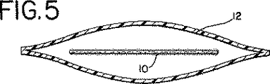
【図5】 図5は、5−5に沿ってとらえた、図1の容器および膜の側面断面図である。
【図6】 図6は、6−6に沿ってとらえた、図2の容器および膜の側面断面図である。
【図7】 図7は、本発明を具体化する容器および膜の代替実施態様の側面断面図である。
【図7A】 図7Aは、本発明を具体化する容器および膜の代替実施態様の側面断面図である。
【図8】 図8は、本発明に従う膜を作製するために使用された装置および方法の模式図である。
【図9】 図9は、図8に示される装置および方法の1段階の拡大斜視図である。ここで、ポリマー溶液/粒子ブレンドが支持体に塗布される。
【図10】 図10は、図9の線10−10に沿ってとらえた、図9の装置の拡大側面断面図である。
【図11】 図11は、本発明の膜を作製する方法において有用な装置の斜視図である。
【図12】 図12は、12−12に沿ってとらえられた、図11の装置の側面断面図である。
【図13】 図13は、本発明に従って作製される膜の別の実施態様の側面図である。
【図14】 図14は、走査型電子顕微鏡を用いた、本発明を具体化する実際の膜の断面図写真(倍率約100倍)である。
【図15】 図15は、走査型電子顕微鏡を用いた、本発明を具体化する実際の膜の断面図写真(倍率約3300倍)である。
【図16】 図16は、走査型電子顕微鏡を用いた、支持体付近でとらえた、本発明を具体化する実際の膜の断面図写真(倍率約1500倍)である。
【図17】 図17は、走査型電子顕微鏡を用いた、膜の外表面付近でとらえた、本発明を具体化する実際の膜の断面図写真(倍率約1600倍)である。
【図18】 図18は、走査型電子顕微鏡を用いた、本発明を具体化する実際の膜の表面写真(倍率約270倍)である。
【図19】 図19は、走査型電子顕微鏡を用いた、本発明を具体化する実際の膜の表面写真(倍率約5500倍)である。
【図20】 図20は、走査型電子顕微鏡を用いた、本発明を具体化する実際の膜の表面写真(倍率約37,000倍)である。
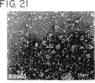
【図21】 図21は、走査型電子顕微鏡を用いた、活性炭粉末粒子の写真(倍率約400倍)である。
【図22】 図22は、走査型電子顕微鏡を用いた、活性炭粉末粒子の写真(倍率約3300倍)である。
【図23】 図23は、走査型電子顕微鏡を用いた、活性炭粉末粒子の写真(倍率約37,000倍)である。
【図24】 図24は、本発明に従って作製された膜による、メチレンブルーの吸収の速度を示すグラフである。
【図25】 図25は、本発明に従って作製された膜による、L−グルタチオンの吸収の速度を示すグラフである。
【図26】 図26は、本発明に従って作製された膜による、パックされたRBCにおけるアクリジン誘導体の吸収の速度を示すグラフである。
【図27】 図27は、本発明に従って作製された膜による、パックされたRBCにおけるグルタチオンの吸収の速度を示すグラフである。
【図28】 図28は、アクリジン化合物およびL−グルタチオンで処置し、そして本発明に従って作製された膜と接触された、パックされたRBCにおける%溶血を示すグラフである。[0001]
The present invention relates to composite membranes and methods for making composite membranes. More particularly, the present invention relates to novel composite membranes comprising particulate material immobilized within a polymer matrix and methods for making such membranes. Methods and devices that use such membranes are particularly useful for removing organic compounds added to biological fluids (eg, blood) as part of a pathogen inactivation procedure.
[0002]
(Background of the Invention)
Human blood contains both cellular and non-cellular components. Examples of cellular components in blood include red blood cells (RBC), white blood cells (WBC), and platelets. Plasma is a non-cellular component of blood and a liquid medium in which cellular components are suspended. Plasma also contains various other components such as proteins, compounds that aid blood clotting (coagulation factors), electrolytes and metabolites.
[0003]
During or after collection, human whole blood is usually separated into its various cellular components (RBC, WBC, platelets, plasma). Typically, this separated component can be stored for some period of time and infused to a patient in need of a particular blood component. For example, collected plasma can be infused into a patient to provide plasma proteins and clotting factors, or to replace lost blood volume. Platelets can be administered to cancer patients whose ability to generate platelets has been impaired by chemotherapy and / or radiation treatment. RBCs can be administered to patients who have experienced rapid blood loss or to improve blood oxygen carrying capacity in patients suffering from anemia and the like.
[0004]
Viruses (eg, hepatitis B virus, hepatitis C virus, human immunodeficiency virus (HIV), human cytomegalovirus and human T-cell lymphoproliferative virus (HTLV)) are now human. It is well known that it can be present in blood and blood components. Certain bacteria (eg, Yersinia enterocolitica) may also be present in human blood. The presence of viruses and / or bacteria in the bloodstream (hereinafter collectively referred to as “pathogens”) poses a risk of infection and disease not only to the host, but also to health care workers who handle blood, And / or when the collected blood or blood component is infused, it poses a risk of infection and disease to recipients of such blood or blood component. Accordingly, the medical industry has attempted to reduce the risk of transfusing blood containing such pathogens by developing methods and devices for removing or inactivating pathogens found in blood components. . As used herein, “pathogen inactivation (and forms thereof)” generally means rendering the pathogen harmless to living organisms. Pathogen inactivation includes killing, destroying, or eradicating the pathogen (either virus or bacteria) or inhibiting the ability of the pathogen to replicate, either directly or indirectly. A “compound that inactivates pathogens” refers to a compound used in pathogen inactivation (including degradation products of such compounds).
[0005]
One initial attempt to remove viruses from blood, for example, included filtration of blood and blood components to remove intracellular viruses contaminated in white blood cells (Rawal et al., “Reduction of Human Immunofluency Virus-Infected”. Cells From Donor Blood by Leukocyte Filtration "Transfusion, 460-462 (1989)).
[0006]
Other prior methods for inactivating viruses, and particularly extracellular viruses in blood, include the use of “surfactants” to purify pathogens from steam sterilization of blood plasma or blood components.
[0007]
Pathogen inactivation (referred to as photoactivation) by treating blood or blood components with photochemicals and light was also considered. When activated by light of the appropriate wavelength, the photochemical agent either kills the virus directly or indirectly inhibits the ability of the virus to replicate. Thus, in either case, the virus is “inactivated”. Several known photochemicals have been used or disclosed for use in inactivating viruses in the blood including: psoralen (described in US Pat. No. 5,459,030). ), Phthalocyanine (eg, Rywkin, S. et al., Photochem. Photobiol. 60: 165-170 (1994)); and toluidine blue O, Azure A, Azure B, Azure C, thionine, methylene blue and dimethylmethylene blue. Phenothiazine dyes, including but not limited to. For example, US Pat. No. 5,527,704 (incorporated herein by reference) discloses a method and apparatus for inactivating viruses in biological fluids. Here, a biological fluid (eg, plasma) is combined with methylene blue and subjected to light of an intensity and wavelength appropriate to activate methylene blue over a period of time.
[0008]
Other methods for treating biological fluids (blood or blood components) that do not involve photoactivation are also known. For example, International Publication No. WO 98/070674 describes mustard conjugated to aziridine. US Pat. Nos. 5,691,132 and 5,559,250, which are incorporated herein by reference, contact RBCs with compounds having nucleic acid binding ligands and mustard groups. A method for treating a biological fluid containing RBCs. Such components are believed to react with the nucleic acid of the pathogen (both virus and bacteria) to form a covalent complex that inhibits replication of the pathogen. Examples of acridine compounds include, but are not limited to, N1, N1-bis (2-chloroethyl) -N4- (6-chloro-2-methoxy-9-acridinyl) -1,4pentanediamine.
[0009]
It may also include certain other organic compounds in the treatment system described above to enhance the effectiveness of the pathogen inactivating compound by reducing or “quenching” the potential side effects of the pathogen inactivating compound. May be desired. For example, inclusion of certain naturally occurring tripeptides (including but not limited to reduced L-glutathione) terminates potential side effects and allows maximum pathogen inactivation by pathogen inactivating compounds. . Other examples of quenchers useful in the pathogen inactivation process include sulfhydryls such as mercaptoethanol (described in Rywkin, S. et al., Transfusion 35: 414-20 (1995)), cysteine, quercetin (Ben- Hur et al., Photochem. Photobiol 57: 984-8 (1993)) and rutin (described in Margollis-Nunno, Transfusion 35: 852-862 (1995)).
[0010]
Many of the pathogen inactivation methods known to date are found in (1) compounds that are not normally present in blood (eg, photochemical dyes, nucleic acid binding agents with mustard groups) or (2) in human blood When including the addition of any compound in excess of the typical concentration (eg, L-glutathione), as many additive compounds as possible from the treated biological fluid prior to infusion to the patient or other recipient It is desirable to remove substantially.
[0011]
For example, a method and apparatus for separating photoactivatable agents used in pathogen inactivation is described in US Pat. No. 5,660,731. In that patent, a photochemical agent such as methylene blue is separated from blood by contacting the photochemical agent with a porous medium containing, for example, activated carbon fibers. The porous medium can be in the form of a web, sheet, cylinder, or can be provided in a filter with an inlet and outlet through which biological fluid passes and thus contacts the porous medium.
[0012]
A similar approach is described in US Pat. No. 5,639,376, which is a filter that removes virus inactivators such as leukocytes and methylene blue, their metabolites and photolysis products from plasma or other blood fractions. Is disclosed. As in US Pat. No. 5,660,731, removal of the antiviral agent is accomplished by contacting the blood with a filter adapted for removal of both, for example, white blood cells and antiviral agents. This filter includes activated carbon as an adsorbent for methylene blue.
[0013]
U.S. Pat. No. 4,728,432 more generally describes a method and device for removing toxic substances contained in blood by adsorption. The adsorbents described in such patents include, for example, activated carbon fixed to a support member. This activated carbon is bound to a polymer.
[0014]
Another example of a method and device for removing organic compounds from biological fluids is US patent application Ser. No. 09 / 003,113 entitled “Methods and Devices for the Reduction of Small Organic Compounds from Brood Products”. (Incorporated herein by reference). The application describes the use of adsorbent particles such as activated carbon beads applied to a support for the removal of acridine, acridine derivatives, methylene blue or thiols in blood products, for example. The activated carbon beads can be contained within a pouch or top package, can be captured within a fiberized matrix, or can be captured within a fiberized matrix and included within a pouch or top package.
[0015]
(Summary of the Invention)
The present invention may find particular application in the medical field, more particularly in the field of pathogen inactivation. Thus, the present invention relates to an apparatus for reducing the concentration of selected organic compounds in a biological fluid. In one aspect of the invention, the device includes a biocompatible container and a membrane disposed within the container. The membrane includes a selected amount of non-fibrotic polymer material and a selected amount of adsorbent material.
[0016]
The present invention also relates to a method for removing selected organic compounds in a biological fluid. In one aspect of the invention, the method can include providing an amount of a biological fluid comprising a selected organic compound. The method further contacts the biological fluid with a membrane, which includes a selected amount of non-fibrotic polymer material and a selected amount of adsorbent material immobilized within the polymer material. Process.
[0017]
The present invention also relates to a flexible composite membrane for reducing the concentration of selected organic compounds in a biological fluid. The membrane includes a selected amount of polymeric material and a selected amount of activated carbon. The activated carbon is substantially immobilized within the polymer matrix. The membrane includes a selectively permeable skin on the outer surface of the membrane.
[0018]
(Detailed description of the drawings)
Referring now to the drawings, the present invention provides for the removal of pathogen inactivating compounds (including pathogen inactivating agents, their by-products and / or other added organic compounds used in the pathogen inactivation process). In relation, it is shown for illustrative purposes only. As described more fully below, certain aspects of the present invention (eg, membranes and methods for making membranes) have applications beyond the field of pathogen inactivation of biological products. For example, the membrane and method of making the membrane may be any other where it is desired that the particulate material have a device (eg, membrane, tube, rod, etc.) that is immobilized by or within the polymer matrix. Can have application in fields and industries. Accordingly, while the detailed description of the invention is generally in the context of pathogen inactivation of biological fluids (eg, blood components), the scope of the invention is set forth in the appended claims.
[0019]
FIG. 1 shows a
[0020]
Briefly referring to the container discussion, the
[0021]
Returning now to the description of the
[0022]
In another alternative, for example, as shown in FIG. 7, the
[0023]
The
[0024]
As described above, the
[0025]
Similarly, the particulate material should be able to be combined with the selected polymer. When the
[0026]
Activated carbon is known as an adsorbent and is a preferred adsorbent for the present invention. Activated carbon is available in bead form, but for the reasons described above, powdered activated carbon may be preferred. Activated carbon is also available from various sources. Examples of activated carbon include Norit (R) Americas Inc. of Marshall, Texas. Activated carbon powders available from Norit Pac 200, Darco S51FF, Darco KB-B, Norit SX Ultra, G-60 Norit (R) A Supra, Norit (R) B Supra and Norit E (R) Supra). Typically, the activated carbon particles are porous and have a diameter of less than about 20μ or even less than 10μ and about 1000m 2 Having a total surface area greater than / g. Particularly useful in making the membranes of the present application is Norit® A Supra activated carbon powder. For example, in Norit® A Supra, the majority of the particles have a diameter of less than about 20 microns and a significant number has a diameter of less than about 10 microns. Norit (registered trademark) A Supra is approximately 2000 m 2 A typical total surface area of / g. Of course, other activated carbons can also be used. Other examples of particulate materials suitable for use in the present invention include porous polystyrene adsorbent beads, which preferably provide smaller particles having a diameter of about 20 μm or less. Can be crushed.
[0027]
As discussed in more detail below, the polymeric and particulate materials described above are combined to form a slurry-like blend that is used to make the
[0028]
Membranes of the type described above (and particularly those derived from polymer solution and particle blends) can be flow cast or blended on a
[0029]
In accordance with one method for making the membrane of the present invention, the polymeric material and particulate material are generally combined in the proportions described above. Specifically, the polymeric material can be first dissolved in a suitable solvent. Various solvents for different polymeric materials can be used. For illustrative purposes only, when the polymer is polyurethane or cellulose acetate, a suitable solvent may be N-methylpyrrolidone (NMP). A suitable solvent for PVC can be tetrahydrofuran, while a suitable solvent for PVDF can be dimethylacetamide (DMAC). Of course, those skilled in the art will appreciate that other solvents may also be used.
[0030]
A selected amount of particulate material can then be added to the dissolved polymer material (polymer solution) to provide a slurry-like blend. This blend is then introduced into the
[0031]
As shown in FIG. 10, the lower portion of the
[0032]
Furthermore, the
[0033]
In an alternative embodiment of the present invention, a second V-shaped chamber (shown in phantom as
[0034]
As shown in FIGS. 9 and 10, this blend can be applied to both sides of the
[0035]
The rotation of
[0036]
Once the solvent is substantially extracted from the membrane, the membrane can be dried. As shown in FIG. 8, after the last extraction bath, the membrane can be introduced into an oven 30 (eg, an air circulation oven). Of course, other forms of drying steps can also be used, including air drying steps or contacting the membrane with a heated surface.
[0037]
Before or after drying, the
[0038]
As described above, the membrane can be further contoured to a pleated or corrugated sheet. An
[0039]
In certain embodiments, the
[0040]
As used herein, the composition of a blend is expressed as the weight percentage of particulate material (eg, activated carbon) in the combined amount of particles and polymer (solid). Thus, for example, 10 grams of activated carbon (or other particles) added to a polymer solution containing 10 grams of polymer and 90 grams of solvent provides a membrane with 50% activated carbon and 50% polymer. Similarly, 30 grams of activated carbon (particles) added to a polymer solution having 10 grams of polymer (polyurethane) has 75% “loading” activated carbon (or other particles) and 25% polyurethane. A film is formed (ie, 30 grams of particles in polymer and particles (40 (10 + 30) grams) are 75% loaded particles). In any case, the amount of activated carbon should be at least 10% by weight, preferably 70% by weight.
[0041]
After blending the activated carbon with the polymer solution, the blend can then be introduced into the
[0042]
The speed of movement of the
[0043]
After extraction of the NMP solvent, the
[0044]
The
[0045]
Other solutions can also be used to treat the
[0046]
Membranes made in accordance with the present invention provide a unique and cost effective method of immobilizing fine particle powders that are typically difficult to handle and prone to shedding. This is particularly advantageous in the field of blood therapy where it is considered undesirable to introduce foreign particles into the blood or other biological fluid. Membranes made according to the present invention are also somewhat unique. This is because the particles are substantially trapped by the polymer matrix without compromising the ability of the powder to act as an adsorbent for organic compounds used in pathogen inactivation treatments. As now understood, the fine powder is widely dispersed throughout the polymer matrix and thus provides many adsorption sites for the molecules of the organic compound. This wide dispersion of powder may also mean that the distance that the organic compound molecules must travel before being captured by the adsorbent powder is shorter.
[0047]
Actual membranes made in accordance with the present invention are shown in FIGS. Specifically, FIGS. 14-20 show membranes made from a blend derived from 10% polyurethane solution (PNO3). To a 10% urethane solution, Norit® A Supra activated carbon powder is added to obtain about 70% charcoal loading (ie, this solid contains 70% activated carbon and 30% polyurethane). Membranes were prepared using the apparatus shown generally in FIG. 8 (using a single chamber 24) and described herein. Polyester mesh was used as a support.
[0048]
The resulting membrane comprises a polymer matrix that appears as a row of sponge-like structures in FIG. As further seen in FIG. 14, the polymer matrix is substantially continuous throughout the membrane, even across a portion of the polyester mesh support. The polyester mesh support appears in cross section as a larger circle or ellipse structure near the center of the membrane. The top and bottom surfaces of the polymer matrix include thin “skin” layers. As seen in FIGS. 15-17, it is believed that the hemispherical granules may be activated carbon particles immobilized within a polymer matrix.
[0049]
FIG. 18 is a photograph of the surface of the membrane and more specifically the skin. As can be seen in FIGS. 18 and 19, the skin is not completely continuous and includes randomly spaced voids across the membrane. When enlarged, charcoal particles retained by the polymer material near the surface of the membrane can be seen (FIGS. 19 and 20). As can be seen in FIG. 20, the activated carbon particles coated with the polymeric material have a woven appearance that is not seen in photographs of the activated carbon particles alone (FIGS. 23-25). The skin layer of the polymer matrix is believed to help prevent the particles from coming off. Importantly, while providing this protective function, the skin layer does not interfere with mass transport and remains permeable to the specific molecules of the organic compound to be removed. When used in a pathogen inactivation process, the membrane skin is permeable to certain pathogen inactivating compounds, but not permeable to, for example, cellular components or other components found in the blood. Absent.
[0050]
To test the effectiveness of the membranes of the present invention, prepared membrane samples were contacted with solutions containing various compounds commonly used in pathogen inactivation procedures. The test procedure and results are shown below.
[0051]
Polyurethane and activated carbon membranes were prepared substantially as described above. The polyurethane / activated carbon blend contained 10% polyurethane PNO3 in combination with 90% NMP solvent. Activated carbon was added to obtain a 70% activated carbon load. This blend was applied to a polyester mesh support substantially as described above to form a membrane. The two membranes were dried and treated with either 1) 0.25% PVOH in a 50/50 water / isopropyl alcohol solution, or 2) a 0.9% NaCl solution. The other membrane served as a control and was either dried only (and not treated with any solution) or not dried at all.
[0052]
Example 1
A solution containing 50 μM methylene blue phosphate buffered saline was prepared and dispensed into test tubes. Membrane samples prepared as described above were placed in each test tube. The ratio of membrane surface to fluid is about 2.0 cm. 2 / Ml. Samples were then removed from the test tubes at defined intervals. The extent of methylene blue absorption was measured by spectrophotometric means (at 630 nm). The results are shown in FIG.
[0053]
(Example 2)
A solution containing 6 mM reduced L-glutathione in phosphate buffered saline was prepared and dispensed into test tubes. Membrane samples prepared as described above were placed in each test tube. The ratio of membrane surface to fluid is about 2.0 cm 2 / Ml. Samples were then removed from the tubes at defined intervals and the extent of absorption was determined by high performance liquid chromatography (HPLC). The results are shown in FIG.
[0054]
(Example 3)
A membrane with 70% loaded activated carbon in a 10% polyurethane (PNO3) solution was prepared essentially as described above. The membrane is 22.7 x 10.7 cm 2 Were cut into two sheets and placed in two separate 1 liter blood bags. Two units (each about 300 ml) of packed RBCs were prepared by standard blood storage procedures, and the acridine derivative of Example 3 (5- (β-carboxyethyl) amino) acridine (abbreviated AD) and L -Glutathione was added to each of these units. Initial concentrations of acridine derivative and L-glutathione were measured. Their concentrations are reported in Table 1 below (time 0). The packed RBC of each unit was transferred to a container containing the sample membrane (above). The ratio of membrane surface to fluid is about 2.5 cm. 2 / Ml. The container was placed on an orbital shaker and stirred at room temperature. Samples were removed for analysis at 1, 4 and 24 hours. The packed RBC samples were centrifuged at maximum RPM in a microcentrifuge, and the plasma supernatant was transferred to another vial for analysis of L-glutathione (GSH) and acridine derivatives by HPLC. Packed RBC samples were also analyzed with a Sysmex cell counter to determine the extent of hemolysis in the various samples. The results are summarized in Table 1 below.
[0055]
[Table 1]
As shown from these examples, about 2.0 cm 2 /Ml-2.5cm 2 A ratio of membrane surface to fluid between / ml is effective in reducing the concentration of pathogen inactivating compounds. Such a ratio is particularly effective for the embodiment shown in FIGS. 1 and 2 (ie, a membrane sheet in a biological fluid container), but 1.0-5.0 cm. 2 Any ratio between / ml may also be effective in these or other embodiments to remove pathogen inactivating compounds.
[0057]
(Example 4)
The ability to remove pathogen inactivation treatment agents from packed red blood cells with five different membranes (all made according to the present invention) was also evaluated. The evaluated membranes contained 70% loaded activated carbon in a 10% polyurethane (PNO3) solution (as described above). Sample membranes were treated with treatment agents in some cases (eg, test articles 2-5) and shaped as follows (flat or pleated). For comparison, test article 6 (control) was a packed and treated RBC container (as described below) without any adsorbent.
[0058]
[Table 2]
Seven units of whole blood compatible with ABO were obtained. Each unit was centrifuged at 4150 rpm in a Sorval RC-3B centrifuge at 5,000 × G for 5 minutes. The supernatant plasma is squeezed to about 25 mM sodium citrate dihydrate, 4.4 mM sodium phosphate dihydrate, 16 mM sodium phosphate dihydrate, 1.5 mM 94 ml of a solution containing adenine and 39.9 mM mannitol (having a pH of about 7.3) was added to each unit. The packed red blood cells were then pooled in a 3 liter container. The measured value of hematocrit was 64%. The packed RBCs were then distributed into 7 separate containers, each container containing approximately 280 ml packed red blood cells. The packed red blood cells were then dispensed into plastic containers and maintained at 4 ° C. for about 4 hours.
[0060]
Next, the cooled container was heated to room temperature. 20 ml of 30 mM glutathione solution (in 4.1% dextrose) was added to the acridine compound [N, N-bis (2-chloroethyl)]-2-aminoethyl 3 [(acridinyl-3-yl) amino] propionate. A pouch containing about 30 mg of dihydrochloride was placed. The powder was lysed and the solution was added to the packed red blood cells and mixed to obtain a final concentration of about 200 μM acridine compound and 2 mM L-glutathione in the packed red blood cells. After transfer to the second container, the dosed packed red blood cells were allowed to stand at room temperature for about 8 hours.
[0061]
Following the 8 hour incubation period, the treated packed red blood cells were aseptically connected to a container containing a membrane made as described above. The container containing packed red blood cells and membranes was placed on an orbital shaker (72 cycles / min) for 8 hours at room temperature. After 8 hours, these units were transferred to a 4 ° C. reservoir where they were agitated on a platelet shaker with a duration of 2 minutes every 4 hours. Samples were collected every 2 hours for the first 8 hours after placing the sample in the container containing the membrane. Samples were prepared for HPLC analysis and the acridine derivatives 5-[(β-carboxyethyl) amino] acridine (abbreviated AD) and total L-glutathione (oxidized (GSH) and reduced (GSSH)) The concentration of was determined. Samples were also analyzed for% hematocrit,% hemolysis, hemoglobin, ATP concentration, pH and potassium (K + leakage). Samples were also collected and analyzed after exposure to this membrane at 4 ° C. for 1 and 2 weeks. The results after 8 hours of exposure to this membrane are also summarized in Table 2 and FIGS. The results after 1 and 2 weeks exposure to this membrane are summarized in Tables 4 and 5.
[0062]
[Table 3]
[Table 4]
[Table 5]
As noted above and shown in FIG. 26, substantial absorption of the acridine derivative was obtained within 5 hours. Substantial absorption of L-glutathione (oxidized and reduced) was also achieved within 24 hours (FIG. 27). Hemolysis and ATP levels remained acceptable for transfusion into RBC recipients (FIG. 28).
[0066]
The invention has been described with respect to selected embodiments and methods for purposes of illustration only. However, it is understood that various modifications of the embodiments and methods described herein are possible in accordance with the appended claims.
[Brief description of the drawings]
FIG. 1 is a perspective view of a container containing a membrane embodying the present invention.
FIG. 2 is a perspective view of a container containing an alternative embodiment of a membrane embodying the present invention.
FIG. 3 is an enlarged partial side cross-sectional view of a membrane (with a support) made in accordance with the present invention, taken along 3-3 in FIG.
FIG. 4 is an enlarged partial side cross-sectional view of a membrane (without a support) made in accordance with the present invention.
FIG. 5 is a side cross-sectional view of the container and membrane of FIG. 1 taken along line 5-5.
FIG. 6 is a side cross-sectional view of the container and membrane of FIG. 2 taken along 6-6.
FIG. 7 is a side cross-sectional view of an alternative embodiment of a container and membrane embodying the present invention.
FIG. 7A is a side cross-sectional view of an alternative embodiment of a container and membrane embodying the present invention.
FIG. 8 is a schematic diagram of an apparatus and method used to make a membrane according to the present invention.
9 is an enlarged perspective view of one stage of the apparatus and method shown in FIG. Here, the polymer solution / particle blend is applied to the support.
FIG. 10 is an enlarged side cross-sectional view of the device of FIG. 9 taken along line 10-10 of FIG.
FIG. 11 is a perspective view of an apparatus useful in the method of making a film of the present invention.
12 is a side cross-sectional view of the apparatus of FIG. 11, taken along 12-12. FIG.
FIG. 13 is a side view of another embodiment of a membrane made in accordance with the present invention.
FIG. 14 is a cross-sectional photograph (approximately 100 times magnification) of an actual film embodying the present invention using a scanning electron microscope.
FIG. 15 is a cross-sectional photograph (magnification of about 3300 times) of an actual film embodying the present invention using a scanning electron microscope.
FIG. 16 is a cross-sectional photograph (magnification of about 1500 times) of an actual film embodying the present invention, taken in the vicinity of a support, using a scanning electron microscope.
FIG. 17 is a cross-sectional photograph (approximately 1600 times magnification) of an actual film embodying the present invention, taken near the outer surface of the film, using a scanning electron microscope.
FIG. 18 is a surface photograph (magnification of about 270 times) of an actual film embodying the present invention using a scanning electron microscope.
FIG. 19 is a photograph of the surface of an actual film embodying the present invention using a scanning electron microscope (magnification approximately 5500 times).
FIG. 20 is a surface photograph (magnification of about 37,000 times) of an actual film embodying the present invention using a scanning electron microscope.
FIG. 21 is a photograph (magnification of about 400 times) of activated carbon powder particles using a scanning electron microscope.
FIG. 22 is a photograph of activated carbon powder particles (magnification approximately 3300 times) using a scanning electron microscope.
FIG. 23 is a photograph (magnification of about 37,000 times) of activated carbon powder particles using a scanning electron microscope.
FIG. 24 is a graph showing the rate of absorption of methylene blue by a membrane made in accordance with the present invention.
FIG. 25 is a graph showing the rate of L-glutathione absorption by membranes made in accordance with the present invention.
FIG. 26 is a graph showing the rate of absorption of acridine derivatives in packed RBCs by membranes made in accordance with the present invention.
FIG. 27 is a graph showing the rate of glutathione absorption in packed RBCs by membranes made in accordance with the present invention.
FIG. 28 is a graph showing% hemolysis in packed RBCs treated with acridine compound and L-glutathione and contacted with membranes made in accordance with the present invention.
Claims (28)
生体適合性容器;
該容器の内部に配置された複合膜であって、該膜が、選択された量の粒子性吸着材料とブレンドされた選択された量の繊維化していないポリマー材料を含み、そして該膜は該膜の外側面上に選択的に透過性のスキンをさらに含む、膜;
を含む、装置。An apparatus for reducing the concentration of a selected organic compound in a biological fluid, the apparatus comprising:
Biocompatible containers;
A composite membrane disposed within the container, the membrane comprising a selected amount of non-fibrotic polymer material blended with a selected amount of particulate adsorbent material, and the membrane comprising the membrane A membrane further comprising a selectively permeable skin on the outer surface of the membrane;
Including the device.
該生物学的流体を複合膜と接触させるための手段であって、ここで該生物学的流体が、選択された有機化合物を含み、該膜が、ポリマー材料内に実質的に固定化された選択された量の活性炭とブレンドされた選択された量の繊維化していない該ポリマー材料を含み、そして該膜が該膜の表面上に選択的に透過性のスキンを含む、手段;
を備える、システム。A system for selectively removing selected organic compounds from a biological fluid, the system comprising:
Means for contacting the biological fluid with a composite membrane, wherein the biological fluid comprises a selected organic compound and the membrane is substantially immobilized within a polymeric material. It includes not fiberizing activated carbon blended with selected amounts of selected amount the polymer material, and the membrane comprises a selectively permeable skin on the surface of the film, means;
A system comprising:
選択された量のポリマー材料および該ポリマー材料内に実質的に固定化された選択された量の活性炭粒子;
を含み、ここで該活性炭粒子は、該膜に内側部分および該膜の外側面上に選択的に透過性のスキンを提供するように、該ポリマー材料にわたって不均質に分散されている、
複合膜。A flexible composite membrane for reducing the concentration of selected organic compounds in a biological fluid, the membrane comprising:
A selected amount of polymer material and a selected amount of activated carbon particles substantially immobilized within the polymer material;
Wherein the activated carbon particles are heterogeneously dispersed across the polymeric material to provide the membrane with a selectively permeable skin on the inner portion and the outer surface of the membrane .
Composite membrane.
Applications Claiming Priority (3)
| Application Number | Priority Date | Filing Date | Title |
|---|---|---|---|
| US09/111,655 | 1998-07-08 | ||
| US09/111,655 US6099734A (en) | 1998-07-08 | 1998-07-08 | Apparatus, membranes and methods for removing organic compounds from a biological fluid |
| PCT/US1999/014474 WO2000002649A1 (en) | 1998-07-08 | 1999-06-25 | Apparatus, membranes and methods for removing organic compounds from a biological fluid |
Publications (3)
| Publication Number | Publication Date |
|---|---|
| JP2002520137A JP2002520137A (en) | 2002-07-09 |
| JP2002520137A5 JP2002520137A5 (en) | 2006-08-17 |
| JP4344976B2 true JP4344976B2 (en) | 2009-10-14 |
Family
ID=22339728
Family Applications (1)
| Application Number | Title | Priority Date | Filing Date |
|---|---|---|---|
| JP2000558905A Expired - Lifetime JP4344976B2 (en) | 1998-07-08 | 1999-06-25 | Apparatus, membrane and method for removing organic compounds from biological fluids |
Country Status (7)
| Country | Link |
|---|---|
| US (1) | US6099734A (en) |
| EP (1) | EP1094883A4 (en) |
| JP (1) | JP4344976B2 (en) |
| AU (1) | AU748068B2 (en) |
| BR (1) | BR9912523A (en) |
| CA (1) | CA2336580A1 (en) |
| WO (1) | WO2000002649A1 (en) |
Families Citing this family (31)
| Publication number | Priority date | Publication date | Assignee | Title |
|---|---|---|---|---|
| AU749358B2 (en) * | 1998-01-23 | 2002-06-27 | Pall Corporation | Biological fluid treatment system |
| US6099734A (en) * | 1998-07-08 | 2000-08-08 | Baxter International Inc. | Apparatus, membranes and methods for removing organic compounds from a biological fluid |
| US6908553B1 (en) * | 1998-07-08 | 2005-06-21 | Baxter International Inc. | Composite membrane with particulate matter substantially immobilized therein |
| US6969367B2 (en) * | 2000-02-02 | 2005-11-29 | Xepmed, Inc. | Extracorporeal pathogen reduction system |
| KR20020014281A (en) * | 2000-08-17 | 2002-02-25 | 윤정석 | A virus-immunoadsorbent composition and an apparatus for removing a virus using it |
| US20020131958A1 (en) * | 2001-01-22 | 2002-09-19 | John Chapman | Method for purifying a biological composition |
| WO2003053348A2 (en) * | 2001-12-12 | 2003-07-03 | Hydration Technologies, Inc. | Direct osmotic hydration devices |
| WO2004052270A1 (en) * | 2002-12-12 | 2004-06-24 | Asahi Kasei Kabushiki Kaisha | Virus-removing bag and virus-removing method using the same |
| SE525177C2 (en) * | 2003-03-26 | 2004-12-14 | Addsafe Techology Ab | Apparatus for a body fluid bag comprising a filtration member and a retransfusion member mechanically connected to a single unit, and a transfusion unit |
| EP1685852A1 (en) * | 2005-02-01 | 2006-08-02 | Fondation pour la Recherche Diagnostique | Set of disposable bags for viral inactivation of biological fluids |
| US8603805B2 (en) | 2005-04-22 | 2013-12-10 | Hyclone Laboratories, Inc. | Gas spargers and related container systems |
| FR2941385B1 (en) | 2009-01-23 | 2011-04-01 | Millipore Corp | METHOD FOR PROVIDING A CIRCUIT FOR BIOLOGICAL LIQUID AND CIRCUIT OBTAINED |
| AU2010286628B8 (en) * | 2009-08-26 | 2015-11-19 | Global Life Sciences Solutions Usa Llc | Continuous recovery harvest bag |
| FR2955119B1 (en) | 2010-01-13 | 2012-12-28 | Millipore Corp | CIRCUIT FOR BIOLOGICAL LIQUID |
| FR2960795B1 (en) | 2010-06-08 | 2012-07-27 | Millipore Corp | DEVICE FOR A PLANT FOR TREATING BIOLOGICAL LIQUID |
| FR2960794B1 (en) | 2010-06-08 | 2012-07-27 | Millipore Corp | DEVICE FOR A PLANT FOR TREATING BIOLOGICAL LIQUID |
| FR2960796B1 (en) | 2010-06-08 | 2014-01-24 | Millipore Corp | DEVICE FOR A PLANT FOR TREATING BIOLOGICAL LIQUID |
| FR2961713B1 (en) | 2010-06-23 | 2012-08-10 | Millipore Corp | POCKET FOR CIRCUIT OF A BIOLOGICAL LIQUID TREATMENT FACILITY |
| FR2961711B1 (en) | 2010-06-23 | 2012-08-17 | Millipore Corp | POCKET FOR CIRCUIT OF A BIOLOGICAL LIQUID TREATMENT FACILITY |
| US9376655B2 (en) | 2011-09-29 | 2016-06-28 | Life Technologies Corporation | Filter systems for separating microcarriers from cell culture solutions |
| IN2014DN02477A (en) | 2011-09-30 | 2015-05-15 | Life Technologies Corp | |
| MX355832B (en) * | 2012-07-09 | 2018-05-02 | Fosmo Med Inc | Devices using membrane mediated forward osmosis. |
| FR2993572B1 (en) | 2012-07-23 | 2016-04-15 | Emd Millipore Corp | CIRCUIT FOR BIOLOGICAL LIQUID COMPRISING A PINCH VALVE |
| US9079690B1 (en) | 2014-06-26 | 2015-07-14 | Advanced Scientifics, Inc. | Freezer bag, storage system, and method of freezing |
| CN108135936A (en) | 2015-06-26 | 2018-06-08 | 塞鲁斯公司 | Cryoprecipitate composition and preparation method thereof |
| US10799533B2 (en) | 2015-10-23 | 2020-10-13 | Cerus Corporation | Plasma compositions and methods of use thereof |
| CN208684945U (en) | 2016-12-01 | 2019-04-02 | 生命科技股份有限公司 | Filter bag assembly and filtration system |
| US11235090B2 (en) | 2017-03-03 | 2022-02-01 | Cerus Corporation | Kits and methods for preparing pathogen-inactivated platelet compositions |
| EP3691775A1 (en) | 2017-10-05 | 2020-08-12 | Fresenius Medical Care Holdings, Inc. | Polysulfone-urethane copolymer, membranes and products incorporating same, and methods for making and using same |
| RU2699971C1 (en) * | 2018-06-28 | 2019-09-11 | Николай Николаевич Петухов | Membrane polyfunctional device for biological fluid treatment |
| RU2727691C1 (en) * | 2019-09-09 | 2020-07-22 | Николай Николаевич Петухов | Device for sorption treatment of biological fluid and method of use thereof (embodiments) |
Family Cites Families (30)
| Publication number | Priority date | Publication date | Assignee | Title |
|---|---|---|---|---|
| GB1000038A (en) * | 1960-12-06 | |||
| NL287283A (en) * | 1961-03-27 | |||
| CA944226A (en) * | 1970-10-13 | 1974-03-26 | Abitibi Paper Company Ltd. | Apparatus and method for coating a web |
| US3996131A (en) * | 1971-06-16 | 1976-12-07 | Universal Oil Products Company | Precoat for permeability separation systems |
| GB1478971A (en) * | 1973-07-05 | 1977-07-06 | Univ Strathclyde | Solute-adsorptive material |
| GB1577714A (en) * | 1975-10-29 | 1980-10-29 | Univ Strathclyde | Blood purification module |
| SE441143B (en) * | 1976-09-02 | 1985-09-16 | Hoechst Ag | MEMBRANE UNIT AND DEVICE FOR DISPOSAL OF BLOOD METABOLITES |
| JPS5928972A (en) * | 1982-08-10 | 1984-02-15 | 株式会社日本メデイカル・サブライ | Adsorbing body for purifying blood and production thereof |
| US4748120A (en) * | 1983-05-02 | 1988-05-31 | Diamond Scientific Co. | Photochemical decontamination treatment of whole blood or blood components |
| US4693981A (en) * | 1983-12-20 | 1987-09-15 | Advanced Genetics Research Institute | Preparation of inactivated viral vaccines |
| US4610792A (en) * | 1985-01-14 | 1986-09-09 | Memtek Corporation | Membrane filtration process |
| SE452854B (en) * | 1985-01-17 | 1987-12-21 | Gedevelop Ab | FLUIDUM PERMEABLE FIBER MATRIX AND SET FOR ITS PREPARATION |
| US4735193A (en) * | 1985-02-08 | 1988-04-05 | Uop Inc. | Separation of a monosaccharide with mixed matrix membranes |
| US4957943A (en) * | 1988-10-14 | 1990-09-18 | Minnesota Mining And Manufacturing Company | Particle-filled microporous materials |
| JP2805709B2 (en) * | 1989-04-04 | 1998-09-30 | 株式会社アイアイシー | Water purifier |
| US5071610A (en) * | 1990-02-23 | 1991-12-10 | Minnesota Mining And Manufacturing Company | Method of making a controlled pore composite polytetrafluoroethylene |
| US5197208A (en) * | 1991-02-06 | 1993-03-30 | Combe Incorporated | Odor-adsorbent activated charcoal |
| US5505841A (en) * | 1991-03-11 | 1996-04-09 | Pirbazari; Massoud | Microfiltration and adsorbent particle suspension for removing contaminants from water |
| US5312576B1 (en) * | 1991-05-24 | 2000-04-18 | World Properties Inc | Method for making particulate filled composite film |
| US5277820A (en) * | 1992-02-06 | 1994-01-11 | Hemocleanse, Inc. | Device and method for extracorporeal blood treatment |
| US5472607A (en) * | 1993-12-20 | 1995-12-05 | Zenon Environmental Inc. | Hollow fiber semipermeable membrane of tubular braid |
| US5639376A (en) * | 1994-01-10 | 1997-06-17 | Hemasure, Inc. | Process for simultaneously removing leukocytes and methylene blue from plasma |
| US5647985A (en) * | 1994-10-17 | 1997-07-15 | Baxter International Inc. | Whole blood leukodepletion and platelet filter |
| US5660731A (en) * | 1994-11-08 | 1997-08-26 | Pall Corporation | Filter for separating photoactive agent |
| US5691132A (en) * | 1994-11-14 | 1997-11-25 | Cerus Corporation | Method for inactivating pathogens in red cell compositions using quinacrine mustard |
| US6114108A (en) * | 1995-08-29 | 2000-09-05 | V.I. Technologies, Inc. | Methods and compositions for the selective modification of viral nucleic acids |
| US6228995B1 (en) * | 1996-04-09 | 2001-05-08 | Therakos, Inc. | Method for removal of psoralens from biological fluids |
| EP0954374B1 (en) * | 1997-01-06 | 2004-11-24 | Cerus Corporation | Adsorbens and devices for the reduction of small organic compounds from blood products |
| US5914039A (en) * | 1997-07-01 | 1999-06-22 | Zenon Environmental Inc. | Filtration membrane with calcined α-alumina particles therein |
| US6099734A (en) * | 1998-07-08 | 2000-08-08 | Baxter International Inc. | Apparatus, membranes and methods for removing organic compounds from a biological fluid |
-
1998
- 1998-07-08 US US09/111,655 patent/US6099734A/en not_active Expired - Lifetime
-
1999
- 1999-06-25 BR BR9912523-4A patent/BR9912523A/en not_active IP Right Cessation
- 1999-06-25 EP EP99931936A patent/EP1094883A4/en not_active Withdrawn
- 1999-06-25 CA CA002336580A patent/CA2336580A1/en not_active Abandoned
- 1999-06-25 WO PCT/US1999/014474 patent/WO2000002649A1/en active IP Right Grant
- 1999-06-25 JP JP2000558905A patent/JP4344976B2/en not_active Expired - Lifetime
- 1999-06-25 AU AU48344/99A patent/AU748068B2/en not_active Expired
Also Published As
| Publication number | Publication date |
|---|---|
| EP1094883A1 (en) | 2001-05-02 |
| AU4834499A (en) | 2000-02-01 |
| JP2002520137A (en) | 2002-07-09 |
| EP1094883A4 (en) | 2003-03-19 |
| WO2000002649A1 (en) | 2000-01-20 |
| US6099734A (en) | 2000-08-08 |
| AU748068B2 (en) | 2002-05-30 |
| BR9912523A (en) | 2001-09-18 |
| CA2336580A1 (en) | 2000-01-20 |
Similar Documents
| Publication | Publication Date | Title |
|---|---|---|
| JP4344976B2 (en) | Apparatus, membrane and method for removing organic compounds from biological fluids | |
| US6908553B1 (en) | Composite membrane with particulate matter substantially immobilized therein | |
| CA2153010C (en) | Filter for separating photoactive agent | |
| US5547576A (en) | Pathogenic substance removing material and a blood filter containing the material | |
| EP2461847B1 (en) | Device for eliminating biologically harmful substances from bodily fluids | |
| JP4453248B2 (en) | Method for producing hollow fiber membrane and hollow fiber membrane module | |
| EP0569229A1 (en) | High efficiency removal of low density lipoprotein-cholesterol from whole blood | |
| KR0129797B1 (en) | Fitermaterial, apparatus and method for removing leukocytes | |
| AU2002228363B2 (en) | Filter for processing blood and process for producing the same | |
| EP0488095A1 (en) | High efficiency removal of low density lipoprotein-cholesterol from whole blood | |
| JPH08508047A (en) | Method and apparatus for treating body fluids | |
| JP2003527230A (en) | Flow devices for the reduction of compounds from biological compositions and methods of use thereof | |
| JP2003512093A (en) | Filtration unit for virucidal substances | |
| JP3741320B2 (en) | Leukocyte selective removal filter material | |
| JP2804055B2 (en) | Preparation method of non-infectious substance containing virus antigen or antibody | |
| JPH06510455A (en) | Gas plasma treated porous medium and separation method using the same | |
| JP3992185B2 (en) | Method for producing hollow fiber membrane | |
| JPH04338223A (en) | Treatment of permselective membrane | |
| JPH11267199A (en) | Blood treatment method and device | |
| EP0570232A2 (en) | Microporous polysulfone supports suitable for removal of low density lipoprotein-cholesterol | |
| JP2003175321A (en) | Method for manufacturing hollow fiber membrane | |
| JP4678063B2 (en) | Hollow fiber membrane module | |
| JP4533706B2 (en) | Filtration method and system | |
| JP3992187B2 (en) | Method for producing hollow fiber membrane | |
| Davankov et al. | Hypercrosslinked Polystyrene as Hemosorbents |
Legal Events
| Date | Code | Title | Description |
|---|---|---|---|
| A521 | Request for written amendment filed |
Free format text: JAPANESE INTERMEDIATE CODE: A523 Effective date: 20060614 |
|
| A621 | Written request for application examination |
Free format text: JAPANESE INTERMEDIATE CODE: A621 Effective date: 20060614 |
|
| RD04 | Notification of resignation of power of attorney |
Free format text: JAPANESE INTERMEDIATE CODE: A7424 Effective date: 20070531 |
|
| RD02 | Notification of acceptance of power of attorney |
Free format text: JAPANESE INTERMEDIATE CODE: A7422 Effective date: 20070605 |
|
| A521 | Request for written amendment filed |
Free format text: JAPANESE INTERMEDIATE CODE: A523 Effective date: 20070615 |
|
| A977 | Report on retrieval |
Free format text: JAPANESE INTERMEDIATE CODE: A971007 Effective date: 20070726 |
|
| A131 | Notification of reasons for refusal |
Free format text: JAPANESE INTERMEDIATE CODE: A131 Effective date: 20070807 |
|
| A601 | Written request for extension of time |
Free format text: JAPANESE INTERMEDIATE CODE: A601 Effective date: 20071107 |
|
| A602 | Written permission of extension of time |
Free format text: JAPANESE INTERMEDIATE CODE: A602 Effective date: 20071114 |
|
| A521 | Request for written amendment filed |
Free format text: JAPANESE INTERMEDIATE CODE: A523 Effective date: 20071225 |
|
| A521 | Request for written amendment filed |
Free format text: JAPANESE INTERMEDIATE CODE: A523 Effective date: 20080123 |
|
| A711 | Notification of change in applicant |
Free format text: JAPANESE INTERMEDIATE CODE: A711 Effective date: 20080626 |
|
| A521 | Request for written amendment filed |
Free format text: JAPANESE INTERMEDIATE CODE: A821 Effective date: 20080626 |
|
| TRDD | Decision of grant or rejection written | ||
| A01 | Written decision to grant a patent or to grant a registration (utility model) |
Free format text: JAPANESE INTERMEDIATE CODE: A01 Effective date: 20090630 |
|
| A01 | Written decision to grant a patent or to grant a registration (utility model) |
Free format text: JAPANESE INTERMEDIATE CODE: A01 |
|
| A61 | First payment of annual fees (during grant procedure) |
Free format text: JAPANESE INTERMEDIATE CODE: A61 Effective date: 20090701 |
|
| R150 | Certificate of patent or registration of utility model |
Ref document number: 4344976 Country of ref document: JP Free format text: JAPANESE INTERMEDIATE CODE: R150 Free format text: JAPANESE INTERMEDIATE CODE: R150 |
|
| FPAY | Renewal fee payment (event date is renewal date of database) |
Free format text: PAYMENT UNTIL: 20120724 Year of fee payment: 3 |
|
| FPAY | Renewal fee payment (event date is renewal date of database) |
Free format text: PAYMENT UNTIL: 20120724 Year of fee payment: 3 |
|
| FPAY | Renewal fee payment (event date is renewal date of database) |
Free format text: PAYMENT UNTIL: 20130724 Year of fee payment: 4 |
|
| R250 | Receipt of annual fees |
Free format text: JAPANESE INTERMEDIATE CODE: R250 |
|
| R250 | Receipt of annual fees |
Free format text: JAPANESE INTERMEDIATE CODE: R250 |
|
| R250 | Receipt of annual fees |
Free format text: JAPANESE INTERMEDIATE CODE: R250 |
|
| R250 | Receipt of annual fees |
Free format text: JAPANESE INTERMEDIATE CODE: R250 |
|
| R250 | Receipt of annual fees |
Free format text: JAPANESE INTERMEDIATE CODE: R250 |
|
| R250 | Receipt of annual fees |
Free format text: JAPANESE INTERMEDIATE CODE: R250 |
|
| R250 | Receipt of annual fees |
Free format text: JAPANESE INTERMEDIATE CODE: R250 |
|
| EXPY | Cancellation because of completion of term |