JP4344923B2 - Form fixture for concrete buried hardware and concrete buried hardware unit - Google Patents
Form fixture for concrete buried hardware and concrete buried hardware unit Download PDFInfo
- Publication number
- JP4344923B2 JP4344923B2 JP2003343260A JP2003343260A JP4344923B2 JP 4344923 B2 JP4344923 B2 JP 4344923B2 JP 2003343260 A JP2003343260 A JP 2003343260A JP 2003343260 A JP2003343260 A JP 2003343260A JP 4344923 B2 JP4344923 B2 JP 4344923B2
- Authority
- JP
- Japan
- Prior art keywords
- concrete
- turnbuckle
- mold
- fixing
- hardware
- Prior art date
- Legal status (The legal status is an assumption and is not a legal conclusion. Google has not performed a legal analysis and makes no representation as to the accuracy of the status listed.)
- Expired - Fee Related
Links
Images


Description
本発明は、鉄筋受け等のコンクリート埋設金物を型枠板に固定する固定具、及び該固定具とコンクリート埋設金物との組み合わせユニットに関する。 The present invention relates to a fixture for fixing a concrete buried hardware such as a reinforcing bar receiver to a formwork plate, and a combination unit of the fixture and the concrete buried hardware.
従来、この種の固定具としては、型枠に形成した固定穴に、型枠の裏からボルト等を挿して固定する方法が知られている(例えば、特許文献1〜5参照)。
Conventionally, as this type of fixture, a method is known in which a bolt or the like is inserted into a fixing hole formed in the mold from the back of the mold and fixed (for example, see
しかしながら、型枠の裏からボルト等による固定作業は、少なくとも2人の共同作業となり、しかも、作業しにくいという問題があった。 However, the fixing work using bolts or the like from the back of the formwork is a joint work of at least two people, and there is a problem that the work is difficult.
そのような問題を解消し作業性を向上させた浮き止め金具として、寸法調整回転バックル部の一方側に螺着したボルトにフックを設けるとともに他方側に螺着したボルトに拡開型の固定金具を設け、拡開型の固定金具を、型枠の表側から型枠の固定穴に通し、型枠裏面に係止させて抜け止めとし、寸法調整回転バックル部によって引き締め固定する、一方向差し込み式の金具が知られている(例えば、特許文献6参照)。 As a floating bracket that eliminates such problems and improves workability, a hook is provided on the bolt that is screwed to one side of the dimension-adjusting rotating buckle, and the fixing bracket that is open to the bolt that is screwed to the other side A one-way plug-in type in which an expansion-type fixing bracket is passed from the front side of the formwork through the fixing hole of the formwork, locked to the back of the formwork to prevent it from coming off, and tightened and fixed by the dimension-adjusting rotating buckle (See, for example, Patent Document 6).
従来のコンクリート埋設金物用型枠固定具の一例について、図13〜図18を参照して説明する。 An example of a conventional form fixture for concrete embedded hardware will be described with reference to FIGS.
コンクリート埋設金物用型枠固定具100は、両側に互いに逆向きの雄螺子部101,102が形成されたターンバックルネジロッド103と、ターンバックルネジロッド103の一方の雄螺子部102に螺合する雌ねじ部を有し、型枠104に形成された固定穴105に通して型枠裏面に係止させる抜け止め部材106と、ターンバックルネジロッド103に摺動自在に外嵌されたノロ止めコーン107と、ターンバックルネジロッド103に周面に突設されたアンカー片108と、を有している。抜け止め部材106は、トグルボルトの拡開脚片に相当するものであり、図14に示すように脚片106aを閉じたまま型枠の固定穴に通すと、図15,16に示すように通過した後に脚片106aが抜けなくなるものである。
A concrete embedded metal
一方、コンクリート埋設金物110には、ターンバックルネジロッド103の他方の雄螺子部101に螺合する雌ねじ部111が取り付けられている。図示例のコンクリート埋設金物110は、所謂ボイド工法に用いられるボイドブロックを受ける金物である。
On the other hand, a female threaded
施工手順に従い説明すると、図13〜15に示すように、抜け止め部材106を型枠104の固定穴105に通し、図16に示すようにターンバックルネジロッド103を軸回りに回してコンクリート埋設金物110と抜け止め部材106とを相引き寄せることによって、コンクリート埋設金物110の脚部110aを型枠104に当接させてしっかりと固定する。このとき、ノロ止めコーン107は、図16に示すように、自重によって型枠104に当接している。
Explaining according to the construction procedure, as shown in FIGS. 13 to 15, the
次に、図17に示すように、ボイドブロック120をコンクリート埋設金物110に載せて結束する。コンクリート(不図示)を打設し、固化させた後、図18に示すように、型枠104の裏面に突き出たターンバックルネジロッド103をひねって、弱点切り欠き部103a(図13参照)でねじ切る。
しかしながら、上記従来の一方向差し込み型の浮き止め金具では、固定の際に型枠の裏側(スラブ型枠の場合は、下の階の側)からの作業が不要になるが、コンクリートを打設しそれが固化した後に型枠裏面に突き出したボルトを除去する際に、拡開型の固定金具が設けられているボルトは、コンクリート内部においてはコンクリートと接触して固化しているため、型枠から突き出している部分を、トルクレンチ等を用いて叩き折って除去する必要がある。 However, with the conventional one-way insertion type metal fitting, the work from the back side of the formwork (in the case of a slab formwork, the lower floor side) is not required for fixing, but concrete is placed. However, when removing the bolt protruding from the back of the mold after it has solidified, the bolt with the expansion-type fixing bracket is solidified in contact with the concrete inside the concrete. It is necessary to remove the portion protruding from the surface by tapping with a torque wrench or the like.
このような型枠裏面に突き出たボルト等を折る作業は、従来一般的に行われているが、かなり腕力を要する作業であり、作業者の疲労を伴う作業であった。 Such a work of folding a bolt or the like protruding from the rear surface of the formwork has been generally performed, but is a work that requires a considerable amount of arm force, and is a work that involves worker fatigue.
さらに、前記ボルト等を折った後、折った残りの部分が露出しているとその露出部分から金属の腐食が進行するため、折った後にモルタルで埋める作業が必要であり、作業能率の低下を招いていた。 In addition, if the remaining part is exposed after folding the bolt, etc., the corrosion of the metal proceeds from the exposed part, so it is necessary to fill it with mortar after it is folded, reducing the work efficiency. I was invited.
本発明は、上記従来技術に鑑みて、コンクリート埋設金物のコンクリート内に固定した後の作業を軽減し得るコンクリート金物用型枠固定具を提供することを目的とする。 In view of the above prior art, an object of the present invention is to provide a form fixture for a concrete hardware that can reduce the work after the concrete embedded hardware is fixed in the concrete.
上記目的を達成するため、本発明に係るコンクリート埋設金物用型枠固定具は、第1の手段として、固定用の雄螺子部を有するコンクリート埋設金物を型枠に固定するコンクリート埋設金物用型枠固定具であって、両側に互いに逆向きの雌螺子が形成された一対の連通又は有底の螺子孔を有し、一方側の螺子孔が前記コンクリート埋設金物の雄螺子部を螺合し得る螺子孔とされ、他方側の螺子孔周囲にノロ止め用の型枠当接面が形成されているターンバックル胴と、前記コンクリート埋設金物の雄螺子部と逆向きの雄螺子部を一端側に有し、前記ターンバックル胴の前記他方側の螺子孔に螺着されるターンバックルボルトと、該ターンバックルボルトの他端側に設けられ、型枠に形成された固定穴に通して型枠裏面に係止させる抜け止め部材と、を有することを特徴とする。 In order to achieve the above-mentioned object, a concrete embedded metal mold fixture according to the present invention, as a first means, is a concrete embedded metal mold for fixing a concrete embedded metal having a fixing male screw part to the mold. It is a fixture and has a pair of communicating or bottomed screw holes in which female screws opposite to each other are formed on both sides, and one screw hole can screw the male screw portion of the concrete-embedded hardware. A turnbuckle body, which is a screw hole, and has a mold contact surface for fixing the slot around the screw hole on the other side, and a male screw part opposite to the male screw part of the concrete-embedded hardware on one end side A turnbuckle bolt that is screwed into the screw hole on the other side of the turnbuckle body, and is provided on the other end side of the turnbuckle bolt, and is passed through a fixing hole formed in the mold, and the back of the mold Retaining member to be locked to , Characterized by having a.
また、上記目的を達成するため、本発明に係るコンクリート埋設金物用型枠固定具は、第2の手段として、固定用の雄螺子部を有するコンクリート埋設金物を型枠に固定するコンクリート埋設金物用型枠固定具であって、両側に互いに逆向きの雌螺子が形成された一対の連通又は有底の螺子孔を有し、一方側の螺子孔が前記コンクリート埋設金物の雄螺子部を螺合し得る螺子孔とされ、他方側の螺子孔周囲に該螺子孔を囲み且つ型枠固定穴に嵌入可能なノロ止め用の筒状部が突設されているターンバックル胴と、前記コンクリート埋設金物の雄螺子部と逆向きの雄螺子部を一端側に有し、前記ターンバックル胴の前記他方側の螺子孔に螺着されるターンバックルボルトと、該ターンバックルボルトの他端側に設けられ、型枠に形成された固定穴に通して型枠裏面に係止させる抜け止め部材と、を有することを特徴とする。 Moreover, in order to achieve the said objective, the mold fixing tool for concrete embedments according to the present invention is used as a second means for a concrete embedment for fixing a concrete embedment having a fixing male screw part to a formwork. A mold fixing tool having a pair of communicating or bottomed screw holes formed with female screws opposite to each other on both sides, and the screw holes on one side screw the male screw parts of the concrete-embedded hardware. A turnbuckle body that is formed into a screw hole that can be inserted into the mold fixing hole and surrounds the screw hole around the other screw hole; A turnbuckle bolt having a male screw portion opposite to the male screw portion on one end side and screwed into a screw hole on the other side of the turnbuckle barrel, and provided on the other end side of the turnbuckle bolt. Fixed on the formwork And having a retaining member engaged in a mold back surface, the through.
また、上記目的を達成するため、本発明に係るコンクリート埋設金物用型枠固定具は、第3の手段として、固定用の雄螺子部を有するコンクリート埋設金物を型枠に固定するコンクリート埋設金物用型枠固定具であって、両側に互いに逆向きの雌螺子が形成された一対の連通又は有底の螺子孔を有し、一方側の前記螺子孔が前記コンクリート埋設金物の雄螺子部を螺合し得る螺子孔とされているターンバックル胴と、前記コンクリート埋設金物の雄螺子部と逆向きの雄螺子部を一端側に有し、前記ターンバックル胴の他方側の螺子孔に螺着されるターンバックルボルトと、該ターンバックルボルトの他端側に設けられ、型枠に形成された固定穴に通して型枠裏面に係止させる抜け止め部材と、該ターンバックル胴に摺動自在に外嵌するノロ止め用の環状部材と、を有することを特徴とする。 Moreover, in order to achieve the said objective, the form-fixing tool for concrete embedment according to the present invention is a third means for concrete embedment for fixing a concrete embedment having a fixing male screw part to a formwork as a third means. It is a mold fixture, and has a pair of communicating or bottomed screw holes formed with female screws opposite to each other on both sides, and the screw holes on one side screw the male screw parts of the concrete-embedded hardware. A turnbuckle cylinder that is a screw hole that can be combined, and a male screw part that is opposite to the male screw part of the concrete-embedded hardware is provided on one end side, and is screwed into a screw hole on the other side of the turnbuckle cylinder. Turnbuckle bolts, a retaining member provided on the other end of the turnbuckle bolts, which is secured to the back of the mold through a fixing hole formed in the mold, and slidable on the turnbuckle cylinder Noro fit And having an annular member of use, the.
前記第3の手段において、第4の手段として、前記環状部材を前記抜け止め部材の側へ弾性付勢する弾性体が、前記ターンバックル胴の外周部に設けられていることが好ましい。 In the third means, as a fourth means, it is preferable that an elastic body for elastically urging the annular member toward the retaining member is provided on an outer peripheral portion of the turnbuckle body.
前記第3又は第4の手段において、第5の手段として、前記環状部材の内周面に形成された内向きフランジと、前記ターンバックル胴の外周面に形成されて前記内向きフランジと係合可能な外向きフランジと、を更に有することが好ましい。
前記第1〜第5の何れかの手段において、第6の手段として、前記ターンバックル胴を耐腐食性材料又は防錆処理された金属材料で形成し、且つ、該ターンバックル胴に形成されている前記螺子孔を有底とすることが好ましい。なお、本明細書において「耐腐食性材料」とは、純化学的反応または電気化学的反応によって変質破壊される現象に対する耐性を有する材料を意味し、硬質プラスチックス、セラミックスのほか、ステンレス鋼等の不銹鋼、その他の耐食性合金を含む。
In the third or fourth means, as fifth means, an inward flange formed on the inner peripheral surface of the annular member and an inward flange formed on the outer peripheral surface of the turnbuckle cylinder are engaged. Preferably, it further has a possible outward flange.
In any one of the first to fifth means, as a sixth means, the turnbuckle cylinder is formed of a corrosion-resistant material or a rust-proof metal material, and is formed on the turnbuckle cylinder. It is preferable that the screw hole is bottomed. In the present specification, the term “corrosion resistant material” means a material having resistance to a phenomenon that is altered and destroyed by a pure chemical reaction or an electrochemical reaction. In addition to hard plastics, ceramics, stainless steel, etc. Including stainless steel and other corrosion resistant alloys.
前記第1〜第6の何れかの手段において、第7の手段として、前記ターンバックル胴の外周面に、軸線方向に延在するフィン又はリブを形成することが好ましい。 In any one of the first to sixth means, as a seventh means, a fin or rib extending in the axial direction is preferably formed on the outer peripheral surface of the turnbuckle barrel.
また、本発明の上記目的は、前記第1〜第7の手段の何れかに記載の型枠固定具と、コンクリート埋設金物とを有することを特徴とするコンクリート埋設金物ユニットによって達成される。 Moreover, the said objective of this invention is achieved by the concrete embedment hardware unit characterized by having the mold fixing tool in any one of the said 1st-7th means, and a concrete embedment.
本発明によれば、ターンバックル胴は、それに設けられた型枠当接面、筒状部、或いは、環状部材によって、型枠に形成された固定穴へのノロの進入を阻止する一方、ターンバックル胴の螺子孔が連通又は有底であるため、ターンバックルボルトがコンクリートと接触しないので、コンクリート固化後において、型枠裏面に突き出たターンバックルボルトを螺脱させるだけで、抜け止め部材とともに取り外しでき、斯かる螺脱操作は電動ドライバー等の電動工具を用いて容易になし得るので、作業性が良くなる。 According to the present invention, the turnbuckle cylinder prevents the entry of the slot into the fixing hole formed in the mold frame by the mold frame contact surface, the cylindrical part, or the annular member provided on the turn buckle cylinder. Since the screw hole of the buckle body is in communication or has a bottom, the turnbuckle bolt does not come into contact with the concrete. After solidifying the concrete, just remove the turnbuckle bolt protruding from the back of the formwork and remove it together with the retaining member. The screwing operation can be easily performed using an electric tool such as an electric screwdriver, so that workability is improved.
また、ターバンバックル胴を耐腐食性材料又は防錆処理された金属材料によって形成し、ターンバックル胴の両側に形成されている雌螺子孔を有底の螺子孔とすることにより、型枠裏面に突き出たターンバックルボルトを螺脱した後には、耐腐食性材又は防錆処理された金属材料のターンバックル胴しか露出せず、防錆処理されていない鉄等のように腐食する畏れが無いから、従来のようなモルタル埋め作業が不要となり、作業性が良くなる。 In addition, the turban buckle cylinder is made of a corrosion-resistant material or a rust-proof metal material, and the female screw holes formed on both sides of the turn buckle cylinder are made into bottomed screw holes, so that After unscrewing the protruding turnbuckle bolt, only the turnbuckle body of corrosion-resistant material or rust-proof metal material is exposed, and there is no possibility of corrosion like iron that has not been rust-proofed. The conventional mortar filling work becomes unnecessary and the workability is improved.
本発明に係るコンクリート埋設金物用型枠固定具の第1実施形態について、図1〜6を参照して説明する。図1〜図4は、第1実施例のコンクリート埋設金物用型枠固定具を型枠に固定する手順を順に示し、図5及び図6は構成部品を拡大して示している。なお、全実施形態及び全図を通し、同様の構成部分には同符号を付した。 A first embodiment of a form fixture for a concrete embedded hardware according to the present invention will be described with reference to FIGS. 1 to 4 sequentially show the procedure for fixing the form-fixing tool for concrete embedded hardware according to the first embodiment to the form, and FIGS. 5 and 6 show enlarged components. In addition, the same code | symbol was attached | subjected to the same component through all embodiment and all the figures.
コンクリート埋設金物用固定具1は、互いに逆向きの一対の螺子孔2a、2bを有するターンバックル胴2と、ターンバックル胴2の螺子孔2bに螺着されたターンバックルボルト3と、ターンバックルボルト3に取り付けた抜け止め部材4とを有している。
The concrete embedded
ターンバックル胴2の螺子孔2aには、コンクリート埋設金物の雄螺子部5が螺着され、第1実施形態のコンクリート埋設金物は、ボイドブロック受け金物を例示している。ボイドブロック受け金物6は、いわゆる中空スラブ工法においてボイドブロックB(図4参照)を支持する金物である。図示例のボイドブロック受け金物6は、受け部6aと、脚部6bと、雄螺子部5が形成された連結部6cとが、溶接されて一体となっている。
A
ターンバックル胴2は、硬質塩化ビニル等の腐食に強いプラスチック材料によって形成されるが、ステンレス鋼等のような耐腐食性金属材料によって形成することもできる。ターンバックル胴2は、図5に良く表れているように、略円柱状をしていて、その両端に形成された互いに逆向きの螺子孔2a、2bは有底孔とされおり、これらの螺子孔2a、2bに雄螺子部5及びターンバックルボルト3の螺入された部分が外部に露出しない構成となっている。なお、螺入されたターンバックルボルト3の螺入部分が露出しないようにするためには、螺子孔2a、2bが連通するものであっても良いが、ターンバックルボルト3を取り外した後に、雄螺子部5が露出するので、錆び防止のために螺子孔2bをコンクリート等で埋める必要がある。
The
抜け止め部材4は、それを型枠7の固定穴7aに挿通し、貫通させることにより、ターンバックルボルト3が抜けないように、型枠7の裏面に係止することによって抜け止め作用をなす部材である。
The retaining
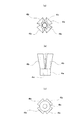
第1実施形態の抜け止め部材4は、図6に良く表れているように、ターンバックルボルト3が挿通された筒状基部4aに、筒状基部4aを基端として斜め放射状に延びる円周配置された複数の拡開片4bを有し、拡開片4bは、ターンバックル胴2の側を向く自由端が、その保有弾性によって半径方向に弾性的に拡開しており、型枠7の固定穴7aに通す際には、図6(b)に一点鎖線で示すようにして拡開片4bが弾性的に縮閉し、固定穴7a通過後にその保有弾性によって再び拡開して抜け止めをなす。抜け止め部材4は、硬質プラスチック材料或いは金属材料により形成することができる。
As shown in FIG. 6, the retaining
なお、拡開片4bが固定穴7a通過後に拡開するためには、図2に示すように、固定穴7a通過後に拡開片4bの先端と型枠7との間に隙間Xが生じていることが必要であり、そのような調節が抜け止め部材4の固定穴7aへの差し込み前になされていることが必要である。
In order to expand the expanded
また、ターンバックル胴2を回して引き締める際にターンバックルボルト3が空回りしないように、図3に示すように、ターンバックル胴2を型枠7から離反する方向に引張り、拡開片4bの先端を木製の型枠7に当接させその摩擦抵抗による回り止め作用をなさせた状態でターンバックル胴2を回す。図示しないが、拡開片4bの先端に型枠7に食い込むような突起を形成しておいて、回り止め機能を高めることができる。ターンバックル胴2を回して、ターンバックルボルト3と雄螺子部5とを引き寄せれば、脚部6bと拡開片4bとによって型枠7を挟み付けにより締め付け、それによってボイドブロック受け金物6が型枠7にしっかりと固定される。
Also, as shown in FIG. 3, the
抜け止め部材4は、ターンバックルボルト3と供回りし、抜け止め部材4がターンバックルボルト3から独立して回転しないように取り付けられている。図示例では、筒状基部4aに雌ねじ4cを形成し、該雌ねじにターンバックルボルト3を螺入し、ターンバックルボルト3の六角ヘッド3aを筒状基部4aに圧締して固定しているが、その他、接着材で固定する等の公知の固定手段を採用し得る。
The retaining
ターンバックル胴2の他方側の螺子孔2b周囲には、螺子孔2bを囲み且つ固定穴7aに嵌入可能なノロ止め用筒状部8が螺子孔2bの軸線方向に突設されている。型枠7は繰り返して再利用されることが多く、固定穴7aの径寸法もほぼ決まっているから、筒状部8の外径を、固定穴7aの内径とほぼ等しいか、僅かに小さくしておくことにより、筒状部8を固定穴7aに嵌入すれば、筒状部8がコンクリート打設の際のノロ止めとなる。
Around the
ターンバックル胴2の外周面に、軸線方向に延在するフィン又はリブ2cが形成されている。これらのフィン又はリブ2cは、コンクリートに埋設されることで、ターンバックル胴2の回り止め作用をなすとともに、取り付け時の回転作業を容易にする。
Fins or
上記第1実施形態のコンクリート埋設金物用型枠固定具1は、型枠7の固定穴7aに抜け止め部材4を通し、拡開片4bを拡開させることによって拡開片4が型枠7の裏面に係止するので、拡開片4がターンバックルボルト3の抜け止めとなる。そして、ターンバックル胴2を引っ張って拡開片4bによる回り止めをしつつターンバックル胴2を回すことにより、型枠7に固定することができる。
In the
コンクリート埋設金物用型枠固定具1が型枠7に取り付けられると、筒状部8が固定穴7aを塞ぐので、コンクリートを打設した際にコンクリートノロが固定穴7aから漏出するのを防ぐことができる。
When the concrete-embedded
コンクリートが固化した後、ターンバックルボルト3を螺子孔2bから螺脱させ、型枠7はスラブから取り外される。ターンバックルボルト3は、そのボルトヘッドを通常の六角ヘッドとしておくことで電動ドリルを用いて簡単に螺脱することができる。
After the concrete is solidified, the
ターンバックルボルト3を螺脱した後、ターンバックル胴2は抜脱されずにコンクリートスラブ中に埋設されているが、ターンバックル胴2をプラスチック材料により形成するとともに螺子孔2bを有底としておくことにより、コンクリート埋設金物を構成しているボイドスラブ受け金物6は、コンクリート及びターンバックル胴2に覆われ、外部の湿気と接触することが無いため、腐食が防がれる。
After the
次に、本発明に係るコンクリート埋設金物用型枠固定具の第2実施形態について、以下に図7を参照して説明する。 Next, a second embodiment of the form fixture for a concrete buried hardware according to the present invention will be described below with reference to FIG.
第2実施形態は、コンクリート埋設金物が鉄筋浮き止めフックの例である。鉄筋浮き止めフック10は、一端にフック10aが形成され、他端に雄螺子部5が形成されている。
The second embodiment is an example in which the concrete embedded hardware is a reinforcing bar floating hook. The reinforcing
コンクリート埋設金物用型枠固定具1は、ターンバックル胴2と、ターンバックル胴2に螺着されたターンバックルボルト3と、ターンバックルボルト3に形成された抜け止め部材4とを有する。ターンバックル胴2は、上記第1実施形態と同様である。
A concrete embedded
第2実施形態では、抜け止め部材4は、ターンバックルボルト3の後部をL字状に折り曲げて形成されている。斯かる構成の抜け止め部材4は、型枠7の固定穴7aに通して引っ掛けるだけで、抜け止めとなる。
In the second embodiment, the retaining
セットする際は、先ず抜け止め部材4を型枠7の固定穴7aに通し、鉄筋11にフック10aを引っ掛けてから、ターンバックル胴2を回して引き締める。なお、ターンバックル胴2を回すとターンバックル胴2が型枠7から離れるが、筒状部8は固定穴7aから抜けないように、予めターンバックルボルト3及び雄螺子部5の螺入度合いを予備調節しておくことが必要である。
When setting, first, the retaining
次に、本発明に係るコンクリート埋設金物用型枠固定具の第3実施形態について、以下に図8に示した施工手順を参照しつつ説明する。 Next, a third embodiment of a concrete fixture for a concrete embedding hardware according to the present invention will be described with reference to a construction procedure shown in FIG.
第3実施形態のコンクリート埋設金物用型枠固定具1は、後述するようにノロ止め用の構成部材が上記第1、第2実施形態と相違し、抜け止め部材は上記第1実施形態と同様であり、コンクリート埋設金物は上記第2実施形態と同様である。
As will be described later, the
コンクリート埋設金物用型枠固定具1は、ターンバックル胴2に摺動自在に外嵌するノロ止め用の環状部材12と 、環状部材12を抜け止め部材4の側へ弾性付勢する弾性体13と、を有する。
The
環状部材12は、ターンバックル胴2と同様にプラスチック材料等の耐腐食性材料によって形成され、ターンバックル胴2の摺動可能に外嵌し得る通孔を有し、且つ、少なくとも抜け止め部材4の側の面が型枠7に当接し得る平坦面を備えている。
The
弾性体13は、図示の例ではコイルバネを採用し、ターンバックル胴2に一体成型された鍔状の座部14に支持されている。弾性体13は、コイルバネに限らず、スポンジゴム、板バネ等種々の弾性体を採用でき、また、ターンバックル胴2への支持も座部によらずに、ターンバックル胴2に形成した孔への差し込み等、公知の支持手段を採用し得る。
In the illustrated example, the
第3実施形態のコンクリート埋設金物用型枠固定具では、抜け止め部材4を型枠7の固定穴7aに差し込めば、弾性体13を構成するコイルバネが環状部材12を押圧するため、その反作用によってターンバックル胴2及びこれに螺着されているコンクリート埋設金物としての鉄筋浮き止めフック10が型枠7から離反する側へ付勢される。
In the mold fixing tool for concrete embedded hardware according to the third embodiment, when the retaining
従って、弾性体13の働きによって、抜け止め部材4の拡開片4bが型枠7の裏面に接触するから、上記第1実施形態の場合のように、拡開片4bを型枠7に接触させるためにコンクリート埋設金物を構成している鉄筋浮き止めフック10を型枠7から離反する側へ引っ張る必要が無くなるか、又は引っ張る力が軽減され得る。
Accordingly, the
即ち、抜け止め部材4を型枠7の固定穴7aに通し、拡開片4bを拡開させた後は、拡開片4bは、弾性体13の付勢力によって型枠7に当接する。拡開片4bが型枠7に当接するため、拡開片4bが木製の型枠7に摩擦係合し、ターンバックル胴2を回転させても、抜け止め部材4に固定のターンバックルボルト3は、型枠7に対して回らない。
That is, after the retaining
また、環状部材12は、弾性体13によって型枠7に当接し、型枠7の固定穴7aを完全に塞ぐことができる。従って、コンクリート打設時にコンクリートノロが固定穴7aに進入することが無い。さらに、弾性体13によって環状部材12を型枠7に付勢するため、上記第2実施形態のように筒状部8が固定穴7aから抜けないように予備調節する必要がない。
Further, the
次に本発明に係るコンクリート埋設金物用型枠固定具の第4実施形態について、以下に図9を参照しつつ説明する。 Next, a fourth embodiment of a form fixture for a concrete embedded hardware according to the present invention will be described below with reference to FIG.
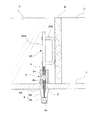
第4実施形態は、コンクリート埋設金物がスリット材支持金物である例を示している。スリット材支持金物20は、スラブC,C間に隙間を形成するために用いられるコンパネ板等のスリット材Sを支えておくための金具である。図示例では、スリット材支持金物20は、雄螺子部5が形成された逆螺子のターンバックルロッド部20aにコ字状金具20bが溶着されている。
4th Embodiment has shown the example whose concrete embedment metal fitting is a slit material support metal fitting. The slit
第4実施形態のターンバックル胴2は、ターンバックル胴2の型枠当接面2dを有している。型枠等接面2dは、螺子孔2bの周囲を形成された平坦面であって、螺子孔2bの軸線に略直交する面によって形成される。第4実施形態のコンクリート埋設金物用型枠固定具1は、上記第1〜第3実施形態と異なり、ターンバックル胴2と抜け止め部材4とが型枠7を挟むことによって、締め付け固定する。
The
従って、第4実施形態では、ターンバックル胴2の型枠当接面2dを型枠7に圧接させ、型枠7の固定穴7a周囲を密閉することができるので、コンクリート打設時にコンクリートノロが固定穴7aに進入することがない。
Therefore, in the fourth embodiment, the
次に、本発明に係るコンクリート埋設金物用型枠固定具の第5実施形態について、図10を参照しつつ説明する。 Next, a fifth embodiment of a concrete fixture for a buried concrete object according to the present invention will be described with reference to FIG.
第5実施形態のコンクリート埋設金物は、手摺り支柱30のアンカー30aを固定するための手摺りアンカー固定金物31である。手摺りアンカー固定金物31は、雄螺子部5が両端に形成された逆U字状部分31aと脚部31bとを有している。
The concrete-embedded hardware of the fifth embodiment is a handrail
第5実施形態の抜け止め部材4は、いわゆるフリップアンカーである。即ち、ターンバックルボルト3の先端に、爪4eが回転自在に支持されている。爪4eは、型枠7の固定穴7aに通す時は、ターンバックルボルト3の溝3aに嵌るので、ターンバックルボルト3の軸幅に収まっているが、固定穴7aを通過すれば、回転して軸幅から飛び出して型枠7の裏面に係止することができるので、抜け止めとなる。
The retaining
次に本発明に係るコンクリート埋設金物用型枠固定具の第6実施形態について図11及び図12を参照しつつ説明する。 Next, a description will be given of a sixth embodiment of the concrete fixture for a buried concrete according to the present invention with reference to FIGS. 11 and 12.
第6実施形態は、ノロ止め部分が上記第1実施形態と相違し、その他の構成は上記第1実施形態と同様である。 The sixth embodiment is different from the first embodiment in the slot stop portion, and the other configurations are the same as those in the first embodiment.
ターンバックル胴2に摺動自在に外嵌された環状部材12’がノロ止め作用をなす。環状部材12’は、図示例において円錐台状の外観形状を有し、ターンバックル胴2が内嵌されている貫通穴12aの内周面に、内向きフランジ12bを有している。一方、ターンバックル胴2の外周面には、内向きフランジ12bが係合し得る外向きフランジ2eが形成されている。外向きフランジ2eに内向きフランジ12aが係合するので、環状部材12’がターンバックル胴2から脱落しない。
An
上記第6実施形態のコンクリート埋設金物用型枠固定具1は、型枠7の固定孔7aに抜け止め部材4を拡開片4bが拡開するまで通し(図11(イ)→(ロ))、ターンバックル胴2を引き上げて拡開片4bを木製型枠7の裏面に係止させつつ、図12(イ)の矢印方向に回転させることで、ボイドブロック受け金物6とターンバックルボルト3とが引き寄せられ、ボイドブロック受け金物6が型枠7にしっかりと固定される。その後、ボイドブロック受け金物6にボイドブロックBを支持させ、ワイヤーにて固定し(図12(ロ))、コンクリートを打設する。環状部材12’は、ターンバックル胴2の外周面に沿ってスライドし、型枠7に当接しており、環状部材12’がターンバックル胴2と型枠7との隙間を埋めるので、コンクリートノロが型枠7の固定孔7aに進入することが防がれる。
In the above-described sixth embodiment, the
なお、上記第1〜第5実施形態を含め本発明に係るコンクリート埋設金物用型枠固定具において、コンクリート固化後にターンバックル胴2から螺脱したターンバックルボルト3は、再利用することができる。
また、本発明に係るコンクリート埋設金物用型枠固定具は、上記したコンクリート埋設金物に限らず、鉄筋受け金物、電源ボックス固定金物、或いは、手摺埋設用貫通管やスラブ開孔を設けるための貫通管等の貫通管部材を固定するための貫通管部材固定金物等、種々のコンクリート埋設金物を固定するのに使用できる。
In addition, in the form-fixing tool for concrete embedded hardware according to the present invention including the first to fifth embodiments, the
Moreover, the form fixture for concrete buried hardware according to the present invention is not limited to the above-mentioned concrete buried hardware, but a reinforcing bar receiving metal, a power box fixing hardware, or a through hole for providing a handrail-embedded through pipe or slab opening. It can be used to fix various concrete-embedded hardware such as a through-tube member fixing hardware for fixing a through-tube member such as a pipe.
1 コンクリート埋設金物用型枠固定具
2 ターンバックル胴
3 ターンバックルボルト
4 抜け止め部材
5 雄螺子部
6 ボイドブロック受け金物
7 型枠
8 筒状部
10 鉄筋浮き止めフック
12,12’ 環状部材
13 弾性体
14 座部
20 スリット材支持金物
31 手摺りアンカー固定金物
DESCRIPTION OF
Claims (9)
両側に互いに逆向きの雌螺子が形成された一対の連通又は有底の螺子孔を有し、一方側の螺子孔が前記コンクリート埋設金物の雄螺子部を螺合し得る螺子孔とされ、他方側の螺子孔周囲にノロ止め用の型枠当接面が形成されているターンバックル胴と、
前記コンクリート埋設金物の雄螺子部と逆向きの雄螺子部を一端側に有し、前記ターンバックル胴の前記他方側の螺子孔に螺着されるターンバックルボルトと、
該ターンバックルボルトの他端側に設けられ、型枠に形成された固定穴に通して型枠裏面に係止させる抜け止め部材と、を有することを特徴とするコンクリート埋設金物用型枠固定具。 A concrete-embedded mold fixing tool for fixing a concrete-embedded hardware having a male screw portion for fixing to a mold,
It has a pair of communicating or bottomed screw holes in which female screws opposite to each other are formed on both sides, and one screw hole is a screw hole that can screw the male screw part of the concrete-embedded hardware, A turnbuckle barrel in which a form contact surface for fixing the slot is formed around the screw hole on the side;
A turnbuckle bolt that has a male screw portion opposite to the male screw portion of the concrete embedded hardware on one end side and is screwed into the screw hole on the other side of the turnbuckle barrel;
A mold fixing tool for concrete embedded hardware, comprising: a retaining member provided on the other end side of the turnbuckle bolt, and having a retaining member that passes through a fixing hole formed in the mold and is locked to the back surface of the mold .
両側に互いに逆向きの雌螺子が形成された一対の連通又は有底の螺子孔を有し、一方側の螺子孔が前記コンクリート埋設金物の雄螺子部を螺合し得る螺子孔とされ、他方側の螺子孔周囲に該螺子孔を囲み且つ型枠固定穴に嵌入可能なノロ止め用の筒状部が突設されているターンバックル胴と、
前記コンクリート埋設金物の雄螺子部と逆向きの雄螺子部を一端側に有し、前記ターンバックル胴の前記他方側の螺子孔に螺着されるターンバックルボルトと、
該ターンバックルボルトの他端側に設けられ、型枠に形成された固定穴に通して型枠裏面に係止させる抜け止め部材と、
を有することを特徴とするコンクリート埋設金物用型枠固定具。 A concrete-embedded mold fixing tool for fixing a concrete-embedded hardware having a male screw portion for fixing to a mold,
It has a pair of communicating or bottomed screw holes in which female screws opposite to each other are formed on both sides, and one screw hole is a screw hole that can be screwed with the male screw portion of the concrete-embedded hardware, A turnbuckle body that is provided with a cylindrical portion for fixing a screw that surrounds the screw hole around the side screw hole and can be fitted into the mold fixing hole;
A turnbuckle bolt that has a male screw portion opposite to the male screw portion of the concrete embedded hardware on one end side and is screwed into the screw hole on the other side of the turnbuckle barrel;
A retaining member provided on the other end side of the turnbuckle bolt, which is passed through a fixing hole formed in the mold and locked to the back of the mold,
A mold fixing tool for concrete embedded hardware characterized by comprising:
両側に互いに逆向きの雌螺子が形成された一対の連通又は有底の螺子孔を有し、一方側の前記螺子孔が前記コンクリート埋設金物の雄螺子部を螺合し得る螺子孔とされているターンバックル胴と、
前記コンクリート埋設金物の雄螺子部と逆向きの雄螺子部を一端側に有し、前記ターンバックル胴の他方側の螺子孔に螺着されるターンバックルボルトと、
該ターンバックルボルトの他端側に設けられ、型枠に形成された固定穴に通して型枠裏面に係止させる抜け止め部材と、
該ターンバックル胴に摺動自在に外嵌するノロ止め用の環状部材と、を有することを特徴とするコンクリート埋設金物用型枠固定具。 A concrete-embedded mold fixing tool for fixing a concrete-embedded hardware having a male screw portion for fixing to a mold,
There are a pair of communicating or bottomed screw holes in which female screws opposite to each other are formed on both sides, and the screw holes on one side are screw holes that can be screwed with the male screw portions of the concrete-embedded hardware. The turnbuckle body,
A turnbuckle bolt having a male screw portion opposite to the male screw portion of the concrete-embedded hardware on one end side, and screwed into a screw hole on the other side of the turnbuckle barrel;
A retaining member provided on the other end side of the turnbuckle bolt, which is passed through a fixing hole formed in the mold and locked to the back of the mold,
A mold fixing tool for concrete embedded hardware, comprising: an annular member for slidably fitting externally to the turnbuckle body.
9. The concrete according to claim 8, wherein the concrete-embedded hardware is a reinforcing bar floating hook, a reinforcing bar receiving hardware, a slit material supporting hardware, a power box fixing hardware, a handrail anchor fixing hardware, or a void block receiving hardware. Embedded hardware unit.
Priority Applications (1)
| Application Number | Priority Date | Filing Date | Title |
|---|---|---|---|
| JP2003343260A JP4344923B2 (en) | 2003-10-01 | 2003-10-01 | Form fixture for concrete buried hardware and concrete buried hardware unit |
Applications Claiming Priority (1)
| Application Number | Priority Date | Filing Date | Title |
|---|---|---|---|
| JP2003343260A JP4344923B2 (en) | 2003-10-01 | 2003-10-01 | Form fixture for concrete buried hardware and concrete buried hardware unit |
Publications (2)
| Publication Number | Publication Date |
|---|---|
| JP2005105738A JP2005105738A (en) | 2005-04-21 |
| JP4344923B2 true JP4344923B2 (en) | 2009-10-14 |
Family
ID=34537288
Family Applications (1)
| Application Number | Title | Priority Date | Filing Date |
|---|---|---|---|
| JP2003343260A Expired - Fee Related JP4344923B2 (en) | 2003-10-01 | 2003-10-01 | Form fixture for concrete buried hardware and concrete buried hardware unit |
Country Status (1)
| Country | Link |
|---|---|
| JP (1) | JP4344923B2 (en) |
Families Citing this family (2)
| Publication number | Priority date | Publication date | Assignee | Title |
|---|---|---|---|---|
| JP5413712B2 (en) * | 2008-09-03 | 2014-02-12 | 株式会社栗本鐵工所 | Cradle |
| KR101301062B1 (en) * | 2013-01-08 | 2013-08-28 | 이세동 | Insert assembly |
-
2003
- 2003-10-01 JP JP2003343260A patent/JP4344923B2/en not_active Expired - Fee Related
Also Published As
| Publication number | Publication date |
|---|---|
| JP2005105738A (en) | 2005-04-21 |
Similar Documents
| Publication | Publication Date | Title |
|---|---|---|
| JP5620112B2 (en) | Anchor and its anchor nut | |
| JP2006022953A (en) | Component for fixing accessory to metal window or door | |
| US4195547A (en) | Anchor bolt assembly | |
| US4966511A (en) | Expansion bolt unit for repeated use | |
| JP2019070249A (en) | Anchor bolt and fixing method using anchor bolt | |
| JP4344923B2 (en) | Form fixture for concrete buried hardware and concrete buried hardware unit | |
| US4537541A (en) | Anchor bolt assembly | |
| KR20090036835A (en) | Set anchor bolt | |
| JP2007239804A (en) | Anchor bolt | |
| JP2010203097A (en) | Member for fixing bolt on wall surface, and method for mounting the same | |
| JP4235667B2 (en) | Metal extension anchor for soft or porous building materials | |
| JPH06193151A (en) | Widening anchor | |
| KR200406105Y1 (en) | A Set Anchor | |
| JP5916182B1 (en) | Bracket | |
| JP2017057940A (en) | Anchor bolt with reverse rotation prevention mechanism | |
| JP2004100952A (en) | Locking tool for bolt and nut, and fastener for bolt | |
| JP2021060095A (en) | Double nut mechanism, and fastening screw mechanism and metallic anchor comprising the same | |
| JP2021071147A (en) | Expandable anchor | |
| JP2021025276A (en) | Post-construction anchor and post-construction anchor bushing | |
| JP2008240790A (en) | Stopper wire connecting member and stopper wire connecting method using same | |
| JP2005194832A (en) | Anchor | |
| JPS6325366Y2 (en) | ||
| JP2001182167A (en) | Burying metal anchor for concrete structure | |
| JP3683205B2 (en) | Connecting wire rope member and method of connecting building pillar and foundation using connecting wire rope member | |
| JP2005299129A (en) | Hole-in anchor bolt |
Legal Events
| Date | Code | Title | Description |
|---|---|---|---|
| A621 | Written request for application examination |
Free format text: JAPANESE INTERMEDIATE CODE: A621 Effective date: 20060908 |
|
| A977 | Report on retrieval |
Free format text: JAPANESE INTERMEDIATE CODE: A971007 Effective date: 20080401 |
|
| TRDD | Decision of grant or rejection written | ||
| A01 | Written decision to grant a patent or to grant a registration (utility model) |
Free format text: JAPANESE INTERMEDIATE CODE: A01 Effective date: 20090610 |
|
| A01 | Written decision to grant a patent or to grant a registration (utility model) |
Free format text: JAPANESE INTERMEDIATE CODE: A01 |
|
| A61 | First payment of annual fees (during grant procedure) |
Free format text: JAPANESE INTERMEDIATE CODE: A61 Effective date: 20090630 |
|
| R150 | Certificate of patent or registration of utility model |
Free format text: JAPANESE INTERMEDIATE CODE: R150 |
|
| FPAY | Renewal fee payment (event date is renewal date of database) |
Free format text: PAYMENT UNTIL: 20120724 Year of fee payment: 3 |
|
| FPAY | Renewal fee payment (event date is renewal date of database) |
Free format text: PAYMENT UNTIL: 20130724 Year of fee payment: 4 |
|
| FPAY | Renewal fee payment (event date is renewal date of database) |
Free format text: PAYMENT UNTIL: 20130724 Year of fee payment: 4 |
|
| S111 | Request for change of ownership or part of ownership |
Free format text: JAPANESE INTERMEDIATE CODE: R313113 |
|
| FPAY | Renewal fee payment (event date is renewal date of database) |
Free format text: PAYMENT UNTIL: 20130724 Year of fee payment: 4 |
|
| R350 | Written notification of registration of transfer |
Free format text: JAPANESE INTERMEDIATE CODE: R350 |
|
| LAPS | Cancellation because of no payment of annual fees |