JP4343862B2 - Image encoding apparatus, image decoding apparatus, control method thereof, computer program, and computer-readable storage medium - Google Patents
Image encoding apparatus, image decoding apparatus, control method thereof, computer program, and computer-readable storage medium Download PDFInfo
- Publication number
- JP4343862B2 JP4343862B2 JP2005059361A JP2005059361A JP4343862B2 JP 4343862 B2 JP4343862 B2 JP 4343862B2 JP 2005059361 A JP2005059361 A JP 2005059361A JP 2005059361 A JP2005059361 A JP 2005059361A JP 4343862 B2 JP4343862 B2 JP 4343862B2
- Authority
- JP
- Japan
- Prior art keywords
- pixel
- data
- color
- vector information
- decoding
- Prior art date
- Legal status (The legal status is an assumption and is not a legal conclusion. Google has not performed a legal analysis and makes no representation as to the accuracy of the status listed.)
- Expired - Fee Related
Links
Images


Description
本発明は画像の可逆符号化/復号する技術に関するものである。 The present invention relates to a technique for lossless encoding / decoding of an image.
従来より、画像の可逆符号化、復号を行う画像処理装置を構成する一手法として予測符号化をベースとするものがある。予測符号化装置は、画像データを予測変換によって予測誤差へと変換する系列変換部と、系列変換部から出力される予測誤差を、ハフマン符号化等のエントロピー符号化を用いて、より冗長性の少ない符号化データへと変換するエントロピー符号化部とによって構成されるのが一般的である。 2. Description of the Related Art Conventionally, there is a technique based on predictive coding as one method for configuring an image processing apparatus that performs lossless encoding and decoding of an image. The predictive encoding device uses a series conversion unit that converts image data into a prediction error by predictive conversion, and a prediction error output from the series conversion unit by using entropy coding such as Huffman coding. Generally, it is configured by an entropy encoding unit that converts data into a small amount of encoded data.
ISOとITU−Tから国際標準の静止画像符号化方式として勧告されるJPEG(ITU-T T.81 | ISO/IEC10918−1)では、Independent Functionとして予測符号化をベースとした可逆符号化方式が規定されている。以下、これをJPEG可逆符号化モードと呼ぶ。JPEG可逆符号化モードでは、近傍画素から着目画素の値を予測する方法として7つの予測式を規定しており、画像に応じて予測方法を選択できるようになっている。 In JPEG (ITU-T T.81 | ISO / IEC10918-1) recommended as an international standard still image coding method by ISO and ITU-T, a lossless coding method based on predictive coding is used as an independent function. It is prescribed. Hereinafter, this is referred to as a JPEG lossless encoding mode. In the JPEG lossless encoding mode, seven prediction formulas are defined as methods for predicting the value of the pixel of interest from neighboring pixels, and the prediction method can be selected according to the image.
図2に従来の画像処理装置のブロック図を示す。同図は上述のJPEG可逆符号化モードにより画像を可逆圧縮する装置の一例である。同図に於いて、201はバッファ、202は成分値予測部、203は減算器、204はハフマンテーブル用メモリ、205は予測誤差符号化部、209は符号列形成部、206,207,208は信号線である。 FIG. 2 shows a block diagram of a conventional image processing apparatus. The figure is an example of an apparatus for reversibly compressing an image using the above-described JPEG lossless encoding mode. In the figure, 201 is a buffer, 202 is a component value prediction unit, 203 is a subtracter, 204 is a Huffman table memory, 205 is a prediction error encoding unit, 209 is a code string forming unit, and 206, 207 and 208 are It is a signal line.
ハフマンテーブル用メモリ204には予測誤差符号化部205において使用されるハフマンテーブルが格納される。ここでは、図6に示すハフマンテーブルが格納されているものとする。
The Huffman
同図を用いて従来の画像処理装置により、RGB各成分が8ビットで表現されたカラー画像を符号化する処理の流れを説明する。 The flow of processing for encoding a color image in which each RGB component is represented by 8 bits by the conventional image processing apparatus will be described with reference to FIG.
まず、信号線208から成分値予測部202において用いる予測方法を選択する予測選択信号mが入力される。予測選択信号mは0〜7までの整数値であり、それぞれに異なる予測式が対応付けられる。使用される予測式と予測選択信号mの対応は図4の通りである。なお、予測選択信号mが0の場合には予測式なしとなっているが、これは予測変換を行わず、各成分をそのまま符号化することを意味する。図中、の記号p,a,b,cについては後述する。
First, a prediction selection signal m for selecting a prediction method used in the component
次に、信号線206から画像データが順に入力される。画素データの入力順序はラスタースキャン順とし、各画素でR,G,Bの順番で成分データが入力されるものとする。R,G,Bをそれぞれ成分番号0,1,2と定義し、画像の左上隅を座標(0,0)として水平右方向画素位置x、垂直下方向画素位置yにある画素の成分番号Cの値をP(x,y,C)と表すこととする。例えば、位置(x、y)=(3,4)である画素が(R,G,B)=(255,128,0)という値を持つ場合、P(3,4,0)=255、P(3,4,1)=128、P(3,4,2)=0と表現する。
Next, image data is sequentially input from the
バッファ201は信号線206から入力される画像データを2ライン分格納する。
The
成分値予測部202はバッファ201から着目する画素の成分値x=P(x,y,C)について直前の画素の同一成分の値a=P(x−1,y,C)、1ライン前の画素の同一成分の値b=P(x,y−1、C)、および斜め左上の画素の同一成分の値c=P(x−1,y−1,C)を取り出し、予測方式選択信号mに従って予測値pを生成する。着目する画素の成分値xとa,b,cの位置関係を図3に示す。なお、着目画素が画像の端部(最上位ライン、左端)に位置する場合、a,b,cは存在しないので、これらa,b,cは“0”と見なして処理を行なう。なお、画像データの入力順は、先に説明した通りであるので、画素a、b、cそれぞれの位置は、既に符号化済みの画素位置となる。
The component
減算器203は符号化対象となる成分値xと予測値pとの差分値を求め、予測誤差eとして出力する。
The
予測誤差符号化部205は、まず、減算器203から入力される予測誤差eを複数のグループに分類して、グループ番号SSSSと、グループごとに定められるビット長の付加ビットを生成する。図5に予測誤差eとグループ番号SSSSの関係を示す。付加ビットはグループ内で予測誤差を特定するための情報であり、ビット長はグループ番号SSSSで与えられる。なお、SSSS=16である場合には例外的にビット長は0である(但し、各成分の精度が8ビットである場合にはSSSS=16は発生しない)。予測誤差eが正であるならば予測誤差eの下位SSSSビットが付加ビットとなり、負である場合にはe−1の下位SSSSビットが付加ビットとなる。付加ビットの最上位ビットは予測誤差eが正であれば1、負であれば0でなる。符号化処理は、まず、メモリ204に格納されているハフマンテーブルを参照して、グループ番号SSSSに対応する符号化データを出力し、SSSSが0または16でない場合には続いてグループ番号により定まるビット長で付加ビットを出力するという順序で行われる。
The prediction
符号列形成部209は信号線208を介して入力される予測選択信号mや、画像の水平方向/垂直方向の画素数、画素を構成する成分の数、各成分の精度などの付加情報と、予測誤差符号化部205から出力される符号化データから、JPEGの規格書に準拠したフォーマットの符号列を形成し、信号線207に出力する。
The code
上述の従来方式による画像処理装置で、CG画像や限定色画像等、各成分の輝度の頻度分布に偏りのある様な画像データを符号化する場合には、上述した系列変換後の予測誤差の発生頻度も、いくつかの特定の予測誤差値に偏ったものとなることがある。 When the image processing apparatus according to the conventional method described above encodes image data having a biased frequency distribution of the luminance of each component, such as a CG image or a limited color image, the prediction error after the above-described series conversion is reduced. The frequency of occurrence may also be biased towards some specific prediction error value.
このような場合、エントロピー符号化による符号長として短い符号長が割り当てられているにも関わらず、殆どもしくは全く発生しない予測誤差が存在することがあり、圧縮率が良くならない。 In such a case, although a short code length is assigned as a code length by entropy coding, there may be a prediction error that hardly or not occurs, and the compression rate does not improve.
このような問題に対して従来から、予測誤差の発生頻度分布が離散的かどうか判別し、判別の結果に応じて予測誤差に対応する符号化データを変更してエントロピー符号化する手法(例えば特許文献1を参照)や、符号化対象画像が離散的な画素値で構成されているかどうか判別し、判別の結果に応じて予測値を修正する手法(例えば特許文献2を参照)などが提案されている。また、画素毎の符号化において、近傍の画素との一致情報が符号化する方法も知られている(例えば特許文献3)。また、複数の予測符号化方法を切替える方法が知られている(特許文献4)。
特許文献1或いは2では、各画素の成分値の発生状況、あるいは予測誤差の発生状況を把握する必要があり、処理の負荷が増える。また、ハフマン符号のようなブロック符号を用いて各成分を予測符号化する場合には、少なくとも1成分当たり最低でも1ビットが必要になる。更に、上記予測符号化技術は、自然画(例えばデジタルカメラで自然界を撮像した画像)については高い圧縮率が期待できるが、文字、線画、CG画像などエントロピの低い画像データでは符号化効率の面でもなお改善の余地がある。かかる点は、特許文献3、4でも同様である。
In
本願発明は、上述の問題点に鑑みてなされたものであり、写真画像等の自然画は勿論のこと、比較的出現する色数が限られたコンピュータグラフィクスや、文書画像に対しも効率良く符号化する技術及びその復号技術を提供しようとするものである。 The present invention has been made in view of the above-mentioned problems, and can efficiently code not only natural images such as photographic images but also computer graphics with a relatively limited number of colors and document images. It is an object of the present invention to provide a technique for decoding and a decoding technique thereof.
かかる課題を解決するため、例えば本発明の画像符号化装置は以下の構成を備える。すなわち、
1画素が複数の色成分データで構成されている画像データを入力し、可逆符号化する画像符号化装置であって、
入力した着目画素データを構成する複数の色成分データそれぞれについて、前記着目画素の近傍の、符号化済みの画素の色成分データを参照して予測値を求め、予測符号化データを生成する予測符号化手段と、
前記着目画素の近傍にあって、符号化済み画素位置にある複数の画素が表わす色数を計数し、色数情報を生成する色数計数手段と、
前記着目画素データと、前記着目画素の近傍にあって符号化済み画素位置にある複数の画素データどうしとを比較し、前記着目画素と同じ色の近傍画素が存在するか否か、及び、存在する場合には前記着目画素に対する該当近傍画素の相対位置を特定するベクトル情報を生成するベクトル情報生成手段と、
前記ベクトル情報を符号化するベクトル情報符号化手段と、
前記色数計数手段より得られた色数情報、及び、前記ベクトル情報生成手段で得られたベクトル情報に基づき、前記予測符号化手段、前記ベクトル情報符号化手段で得られた符号化データから出力用の符号化データを生成する符号化データ生成手段とを備え、
当該符号化データ生成手段は、
前記色数情報で示される色数が所定閾値以下で、且つ、前記ベクトル情報が前記着目画素と同じ色を持つ近傍画素の存在を示す場合、前記ベクトル情報符号化手段で生成された符号化データを、前記着目画素の符号化データとして出力し、
前記色数計数手段で計数された色数が前記所定閾値以下で、且つ、前記ベクトル情報が前記着目画素と同じ色を持つ近傍画素の非存在を示す場合、前記ベクトル情報符号化手段で生成された符号化データと前記予測符号化手段で生成された予測符号化データを、前記着目画素の符号化データとして出力し、
前記色数計数手段で計数された色数が前記所定閾値を超える場合、前記予測符号化手段で生成された予測符号化データを、前記着目画素の符号化データとして出力することを特徴とする。
In order to solve this problem, for example, an image encoding device of the present invention has the following configuration. That is,
An image encoding device that inputs image data in which one pixel is composed of a plurality of color component data and performs lossless encoding,
For each of a plurality of color component data constituting the input pixel-of-interest data, a prediction code that obtains a prediction value by referring to the color component data of an encoded pixel in the vicinity of the pixel of interest and generates predictive encoded data And
Color number counting means for counting the number of colors represented by a plurality of pixels at the encoded pixel position in the vicinity of the target pixel and generating color number information;
Wherein the target pixel data, wherein there in the vicinity of the target pixel is compared with the plurality of pixel data each other in the encoded pixel position, whether neighboring pixels of the same color as the target pixel is present, and the presence a vector information generating means for generating a vector information specifying the relative positions of the corresponding neighboring pixels for the target pixel in the case of,
Vector information encoding means for encoding the vector information;
Based on the color number information obtained from the color number counting means and the vector information obtained by the vector information generation means, output from the encoded data obtained by the predictive coding means and the vector information coding means. Encoded data generation means for generating encoded data for use,
The encoded data generation means includes
Number of colors represented by the color number information is equal to or less than a predetermined threshold value, and, if the vector information indicates the presence of a neighboring pixel having the same color as the target pixel, the generated vector information encoding means encodes data and then output as encoded data of the target pixel,
In the counted number of colors than the predetermined threshold value by the number of colors counting means, and, if the vector information indicates absence of neighboring pixels having the same color as the target pixel, generated by the vector information encoding means predictive coded data and coded data said generated by predictive coding means, and output as coded data of the target pixel,
If the number of colors that are counted in the number of colors counting means exceeds the predetermined threshold, the predictive coding data generated by said prediction encoding means, and outputs the encoded data of the target pixel.
本発明の構成によれば、自然画像等の画像データについての符号化効率は、実質的にこれまでの効率を維持しつつ、且つ、CG画像やテキスト文書等の出現色数が少ない画像については、更なる圧縮率で可逆符号化することが可能になる。 According to the configuration of the present invention, the coding efficiency for image data such as a natural image is substantially the same as that of an image data such as a CG image or a text document while maintaining the conventional efficiency. It becomes possible to perform lossless encoding at a further compression rate.
また、他の発明によれば、上記のような符号化データから可逆復号し、オリジナル画像に完全に復元することが可能になる。 Further, according to another invention, it is possible to perform lossless decoding from the encoded data as described above and to completely restore the original image.
以下添付図面を参照して、本発明に係る実施の形態について詳細に説明する。 Embodiments according to the present invention will be described below in detail with reference to the accompanying drawings.
<第1の実施形態>
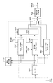
図1は実施形態における画像処理装置のブロック構成図である。
<First Embodiment>
FIG. 1 is a block diagram of an image processing apparatus according to the embodiment.
図1に示すように、本実施形態に係る画像処理装置は、近傍一致判定部101、一致画素位置符号化部102、符号生成部103、符号形成部104、バッファ201、成分値予測部202、減算器203、ハフマンテーブル用メモリ204、予測誤差符号化部205、画素一致検出部107とを備える。同図において206、207、105、106、108は信号線を示す。なお、背景技術で述べた図2の従来の画像処理装置の処理ブロックと同じ動作をするブロックについては同じ番号を付し、説明を省略する。
As shown in FIG. 1, the image processing apparatus according to the present embodiment includes a neighborhood
以下、図1を参照して、本実施形態に係る画像処理装置が行う画像符号化処理について説明する。 Hereinafter, with reference to FIG. 1, an image encoding process performed by the image processing apparatus according to the present embodiment will be described.
本実施形態に係る画像処理装置の符号化対象とする画像データは、RGBカラー画像データであり、各コンポーネント(色成分)は8ビットで0〜255の範囲の輝度値を表現した画素データにより構成されるものとする。符号化対象の画像データは水平方向W画素、垂直方向H画素のサイズとする。従って、入力される画像データはW×H×3バイトのデータ量である。また、水平右方向がX座標の正方向、垂直下方向がY座標の正方向と定義する。また、入力する画像データの入力順序はラスター順とし、各画素はR,G,Bの順番でデータを並べて構成されるものとする。 The image data to be encoded by the image processing apparatus according to the present embodiment is RGB color image data, and each component (color component) is configured by pixel data representing a luminance value in the range of 0 to 255 in 8 bits. Shall be. The image data to be encoded has a size of W pixels in the horizontal direction and H pixels in the vertical direction. Therefore, the input image data has a data amount of W × H × 3 bytes. The horizontal right direction is defined as the positive direction of the X coordinate, and the vertical downward direction is defined as the positive direction of the Y coordinate. The input order of the input image data is a raster order, and each pixel is configured by arranging data in the order of R, G, and B.
さて、符号化対象画像データは信号線206から順に入力される。入力する画像データの供給元は、イメージスキャナでもよいし、所定の記憶装置に格納された画像データでも良く、入力元の種類は問わない。
Now, the encoding target image data is sequentially input from the
画素データの入力順序は既に説明したように、ラスタースキャン順とし、各画素でR,G,Bの順番で成分データが入力される。画素の各成分の輝度値は、R,G,Bをそれぞれ成分番号Cで表現し、C=0はR、C=1はG、C=2はBの各色成分を示すこととする。また、入力する画像の左上隅を座標(0,0)として水平方向画素位置x、垂直方向画素位置yにある画素の成分番号Cの値(実施形態では輝度)をP(x,y,C)と表す。従って、水平方向画素位置「10」、垂直方向画素位置「25」の画素のR、G、B各成分の値はそれぞれP(10,25,0)、P(10,25,1)、P(10,25,2)と表して表わされる。また、成分のまとまりとして画素値を表現する場合にはR,G,Bの各成分値を要素とするベクトルXとして表現する。例えば、R、G、B各成分の値がr、g、bである画素についてはX=(r,g,b)と記述する。 As described above, the input order of the pixel data is the raster scan order, and the component data is input in the order of R, G, and B for each pixel. As for the luminance value of each component of the pixel, R, G, and B are expressed by component number C, C = 0 indicates R, C = 1 indicates G, and C = 2 indicates B. Further, with the upper left corner of the input image as the coordinates (0, 0), the value of the component number C (luminance in the embodiment) of the pixel at the horizontal pixel position x and the vertical pixel position y is set to P (x, y, C). ). Accordingly, the values of the R, G, and B components of the pixel at the horizontal pixel position “10” and the vertical pixel position “25” are P (10, 25, 0), P (10, 25, 1), P, respectively. It is expressed as (10, 25, 2). When pixel values are expressed as a group of components, they are expressed as a vector X having R, G, and B component values as elements. For example, a pixel whose R, G, and B component values are r, g, and b is described as X = (r, g, b).
本画像処理装置は、信号線206から順次入力される画像データの1画素ごとに、符号列形成部104から対応する符号を出力する。
The image processing apparatus outputs a corresponding code from the code
バッファ201は画像データを2ライン分格納する領域を持ち、信号線206から入力される画素データを順次格納し、2ライン分の画素データを記憶保持する。先に述べたように、画像データは各画素がラスター順に、そして各画素ではR,G,Bの順番で成分値が入力される。バッファ201からは、図3の着目画素xの周囲の3画素a,b,cの同一成分値が読み出され、近傍一致判定部101、成分値予測部202に出力される。着目する成分値をP(x,y,C)とするとき、a=P(x−1,y,C)、b=P(x,y−1、C)、c=P(x−1,y−1,C)である。なお、画像の最初のラインや各ラインの先頭/末尾などで、a,b,cが画像の外側となる場合には符号化側と復号側で共通の値を持つよう仮定する。本実施形態ではa,b,c=0とする。また、着目画素xは符号化対象位置であり、周囲画素a,b,cの位置は既に符号化済みの位置になる点に注意されたい。
The
さて、近傍一致判定部101は着目する画素の成分値x=P(x,y,C)と、バッファ201から読み出されるa,b,cを比較して、着目画素と同一画素値を持つ近傍画素の存在の有無を示す情報(以下、一致画素存在情報)105を後段の符号生成部103に、着目画素に一致する近傍画素の相対方向を示す情報(以下、ベクトル情報)106を後段の一致画素位置符号化部102にそれぞれ出力する。
Now, the neighborhood
ここで一致画素存在情報105を生成する場合における2つの画素が同一であるという意味は、2つの画素X1=(r1、g1、b1)と、X2=(r2、g2、b2)があるとき、r1=r2、g1=g2、b1=b2というように全ての成分値が同じである場合を意味する。着目画素の近傍画素a,b,cの中で、着目画素に一致するものが1つでも存在する場合には一致画素存在情報105は“0”、1つも存在しない場合には“1”となる。
Here, when the coincidence
また、ベクトル情報106については次の通りである。
The
着目画素値(色)をXとして直前の画素値をXa、x座標が同じで1ライン前の画素値をXb、斜め左上の画素値をXcとするとき、
X=Xaである場合(Xb、Xcは問わない)、ベクトル情報106は“0”、
X≠Xa、かつ、X=Xbである場合(Xcは問わない)、ベクトル情報106は“1”、
X≠Xa、かつ、X≠Xb、かつ、X=Xcである場合、ベクトル情報106は“2”、
上記以外の場合、ベクトル情報106は“3”とする。
When the pixel value of interest (color) is X, the previous pixel value is Xa, the x coordinate is the same, the pixel value of the previous line is Xb, and the pixel value diagonally upper left is Xc.
When X = Xa (Xb and Xc do not matter), the
When X ≠ Xa and X = Xb (Xc does not matter), the
When X ≠ Xa, X ≠ Xb, and X = Xc, the
In other cases, the
上記の一致画素存在情報105及びベクトル情報106を得るための着目画素の位置を(x、y)とし、これを用いてX,Xa,Xb,Xcを表現したとき、以下の情報を用いれば良いのは明らかである。
X=(P(x,y,0)、P(x,y,1)、P(x,y,2))
Xa=(P(x−1、y、0)、P(x−1,y,1)、P(x−1、y、2))
Xb=(P(x、y−1,0)、P(x,y−1,1),P(x,y−1,2))
Xc=(P(x−1,y−1,0)、P(x−1,y−1,1)、P(x−1,y−1,2))
上記の通りなので、ベクトル情報106が“3”になる場合には、一致画素存在情報105は必ず“1”となる。逆に、一致画素存在情報105が“1”になる場合には、ベクトル情報106は必ず“3”になる。従って、一致画素存在情報105は、ベクトル情報106から得られるものであるが、実施形態では便宜的に別信号として示した。
When the position of the pixel of interest for obtaining the matching
X = (P (x, y, 0), P (x, y, 1), P (x, y, 2))
Xa = (P (x-1, y, 0), P (x-1, y, 1), P (x-1, y, 2))
Xb = (P (x, y-1, 0), P (x, y-1, 1), P (x, y-1, 2))
Xc = (P (x-1, y-1,0), P (x-1, y-1,1), P (x-1, y-1,2))
As described above, when the
一致画素位置符号化部102は、近傍一致判定部101からのベクトル情報106を符号化し、その結果である符号語を符号生成部103へと出力する。本実施形態では図7に示す符号テーブルを用いてベクトル情報106から符号語を生成する(ベクトル情報を符号化する)。
The matching pixel
画素一致検出部107はバッファ201から読み出される着目画素の周囲のa,b,cの3つの画素値を比較して、それら周囲3画素(Xa、Xb、Xc)の間で同一の画素値のペアが存在するか否かを調べ、同一の画素値のペアが検出された場合には“1”、検出されなかった場合には“0”を、周辺画素状態情報108として出力する。
The pixel coincidence detection unit 107 compares the three pixel values a, b, and c around the pixel of interest read from the
即ち、画素一致検出部107は、着目画素Xの周囲の3画素Xa、Xb、Xc間において、「Xa=Xb」、または「Xa=Xc」、または「Xb=Xc」の場合には“1”、それ以外に場合には“0”の周辺画素状態情報108を出力する。なお、周囲3画素内に同一の画素値のペアが少なくとも1つ存在するというのは、周囲3画素間に含まれる色数が2色以下であることと等価である。すなわち、上記は、着目画素の周辺3画素内に存在する色の種類が2種類以下であるか否かの判定結果と考えることができる。
That is, the pixel coincidence detection unit 107 sets “1” when “Xa = Xb”, “Xa = Xc”, or “Xb = Xc” between the three pixels Xa, Xb, and Xc around the pixel of interest X. In other cases, peripheral
因に、画像の先頭ラインを符号化する際、少なくとも近傍画素b、cは画像領域外であるため“0”として扱われることになる。すなわち、少なくともXb=Xcであるので、先頭ラインの符号化する際の周辺画素状態情報108は“1”となる。
For this reason, when encoding the first line of the image, at least the neighboring pixels b and c are outside the image area and are treated as “0”. That is, since at least Xb = Xc, the peripheral
一方、画素の各成分は先に説明した従来方式と同様にして、成分値予測部202、減算器203、予測誤差符号化部205によって、信号線208から入力される予測選択信号mに応じて、各成分毎の予測符号化処理が行われる。なお、この予測選択信号mは、装置の設定によって任意に決めることができる信号であって、少なくとも符号化対象となる全画像データの符号化中は固定である。
On the other hand, each component of the pixel is determined in accordance with the prediction selection signal m input from the
符号生成部103では一致画素位置符号化部102から出力されるベクトル情報の符号語と、予測誤差符号化部205から出力される着目画素の各成分の予測符号化データを一時的に格納する。そして、符号生成部103は、一致画素存在情報105と、周辺画素状態情報108に応じて着目画素に対する符号データを形成し、出力する。具体的には、次の通りである。
i)周辺画素状態情報108が“0”である場合、すなわち、着目画素Xの周辺の3画素Xa、Xb、Xc間で同じ色がペアが1つも存在しない場合、予測誤差符号化部205から出力される各成分の予測符号化データを選択し、出力する。これは、通常の符号化に相当する処理である。
ii)周辺画素状態情報108が“1”(着目画素Xの周辺の3画素Xa、Xb、Xc間で少なくとも同じ色のペアが1つ存在する場合)であり、且つ、一致画素存在情報105が“0”(着目画素の色が、周辺3画素Xa,Xb,Xcのいずれかと同じ場合)の場合、一致画素位置符号化部102から出力されるベクトル情報(ここでは必ず0乃至2のいずれかになる)の符号化データを選択し、出力する。
iii)周辺画素状態情報108が“1”であり、且つ、一致画素存在情報105が“1”(着目画素の色が、周辺3画素Xa,Xb,Xcのいずれとも一致しない場合)の場合、一致画素位置符号化部102から出力されるベクトル情報(必ず“3”)の符号化データを出力し、その後に、予測誤差符号化部205から出力される各成分の予測符号化データを出力する。
The
i) When the surrounding
ii) The peripheral
iii) When the surrounding
図8(a)乃至(c)は、上記3通りの符号化データの符号の構成である。同図(a)は、上記条件i、すなわち、周辺画素状態情報108が“0”である場合の着目画素の符号データを示している。同図(b)は、条件iiの周辺画素状態情報108が“1”であり、且つ、一致画素存在情報105が“0”の場合の着目画素の符号データを示し、同図(c)は条件iiiの周辺画素状態情報108が“1”であり、且つ、一致画素存在情報105が“1”の場合の着目画素の符号データである。
FIGS. 8A to 8C show code configurations of the above three encoded data. FIG. 5A shows the code data of the pixel of interest when the condition i, that is, the peripheral
図8(a)乃至(c)において注目すべき点は、図8(b)の符号化データである。この符号化データが生成される条件は、要するに、着目画素近傍の色数が所定数以下であり、尚且つ、着目画素Xの色が近傍画素Xa,Xb,Xcのいずれかと一致している場合である。同図(b)と、同図(a)或いは(c)と比較すると、もはや各色成分毎の符号化データを不要になり、その符号長は図7に示すように最大でも3ビットで表現でき、更なる圧縮効率が望まれることを意味する。以下に、更に詳しく説明する。 The points to be noted in FIGS. 8A to 8C are the encoded data in FIG. 8B. The condition for generating the encoded data is that the number of colors in the vicinity of the target pixel is equal to or less than the predetermined number and the color of the target pixel X matches any of the neighboring pixels Xa, Xb, and Xc. It is. Compared with FIG. 7B, FIG. 7A or FIG. 9C, the encoded data for each color component is no longer necessary, and the code length can be expressed by 3 bits at the maximum as shown in FIG. This means that further compression efficiency is desired. This will be described in more detail below.
一般に自然画(デジタルカメラで撮像した画像(特に風景画)等)では、近傍の画素がほぼ同じ色になる傾向が高いことが知られている。しかし、これは、近傍の画素の色が完全に一致することを意味するものではないし、むしろ微小な差を有している確率が高い。以下、かかる点を踏まえて、一例を説明する。 In general, it is known that in a natural image (an image (especially a landscape image) taken by a digital camera), neighboring pixels tend to have substantially the same color. However, this does not mean that the colors of neighboring pixels completely match each other, but rather has a high probability of having a minute difference. Hereinafter, an example will be described based on such points.
今、R成分の予測誤差が−31乃至−16、或いは16乃至31の範囲にあるものとする。この場合の予測誤差のグループ番号SSSSは、図5を参照すると、“5”となる。グループ番号「5」の符号語は図6によると“110(B)”(Bは2進数を意味する)であり、図5から付加ビット長は“5”と判明するので、最終的に求めるR成分の予測符号化データは、
“110XXXXX(B)”
となる(Xは、0または1のビット)。
Assume that the R component prediction error is in the range of −31 to −16 or 16 to 31. In this case, the prediction error group number SSSS is “5” with reference to FIG. According to FIG. 6, the code word of the group number “5” is “110 (B)” (B means a binary number), and the additional bit length is found to be “5” from FIG. The prediction encoded data of the R component is
“110XXXX (B)”
(X is a bit of 0 or 1).
一方、ベクトル情報105が“2”の場合の符号語は図7を参照すると、“110(B)”(Bは2進数を意味する)となり、上記R成分の符号化データの先頭3ビットと同じになってしまう。つまり、復号側の処理では、この符号語だけを参照する限りは、“110(B)”がベクトル情報“2”の符号語を意味するのか、グループ番号SSSSが“5”の符号語であるのか区別できない。
On the other hand, referring to FIG. 7, the code word when the
しかし、復号する際、着目画素の近傍画素a,b,cは既に復号済みである点に注意されたい。すなわち、着目画素を復号する際に、近傍画素a,b,c間に、少なくとも同じ色のペアが1つでも存在するか否かは容易に検出できる。近傍画素a,b,cに同じ色のペアが存在する(色数が2以下の場合)場合、符号化データは図8(b)または(c)のいずれかであることが約束され、“110”がベクトル情報の符号語であることが判明する。逆に、近傍画素a,b,cに同じ色のペアが1つも存在しない(色数が3)の場合には、符号化データは、図8(a)に示すように、予測誤差符号化データのみで構成されることが判明する。これはベクトル情報の他の符号語についても同様である。 However, when decoding, it should be noted that neighboring pixels a, b, and c of the pixel of interest have already been decoded. That is, when decoding the pixel of interest, it can be easily detected whether at least one pair of the same color exists between the neighboring pixels a, b, and c. When the same color pair exists in the neighboring pixels a, b, and c (when the number of colors is 2 or less), it is promised that the encoded data is one of FIGS. It turns out that 110 "is a code word of vector information. On the other hand, when there is no pair of the same color in the neighboring pixels a, b, and c (the number of colors is 3), the encoded data is encoded by prediction error encoding as shown in FIG. It turns out that it consists only of data. The same applies to other code words of vector information.
一方、図8(c)の符号化データは、予測誤差符号化データに先立って、ベクトル情報が“3”の符号語“111(B)”が付加される分だけ、同図(a)の符号化データより冗長であると言える。つまり、予測符号化データを採用する場合には、図8(c)のような符号語が発生する確率を低くすることが望まれる。かかる点、本実施形態によれば、同図(c)の符号化データの発生する条件とは、近傍画素a,b,c間に少なくとも同一色のペアが存在する場合(色数が2色以下)としている。換言すれば、近傍画素a,b,cが全て異なる色(色数が3)の場合には、同図(a)の符号化データを生成することになるので、自然画等の場合には必然的に同図(a)の符号化データとなる確率を高めることに成功する。 On the other hand, the encoded data of FIG. 8C is the same as the encoded error data of FIG. 8A in that the code word “111 (B)” with vector information “3” is added prior to the prediction error encoded data. It can be said that the data is more redundant than the encoded data. That is, when predictive encoded data is employed, it is desirable to reduce the probability that a code word as shown in FIG. In this respect, according to the present embodiment, the condition for generating the encoded data in FIG. 5C is that at least a pair of the same color exists between the neighboring pixels a, b, c (the number of colors is two colors). The following). In other words, when the neighboring pixels a, b, and c are all different colors (number of colors is 3), the encoded data of FIG. Inevitably, the probability that the encoded data shown in FIG.
コンピュータグラフィックスの場合、コンピュータ上で人工的に生成した色でペイントすることがほとんどである。従って、コンピュータグラフィクスで、見かけ上、自然画を模した画像を生成したとした場合に利用される色数は自然画よりは少ない。換言すれば、近傍画素間で色が完全に一致する割合は自然画より格段に多くなるので、同図(b)の符号化データが生成される確率は高くなり、従来の可逆符号化である予測符号化よりも、数段優れた圧縮率が期待できる。特に、通常の文字で構成されるテキスト文書画像の場合には、色数は2色(黒と白)しか存在しないので、図8(a)のような符号化データが生成される確率を高めることができる。 In the case of computer graphics, painting is usually performed with colors artificially generated on a computer. Therefore, the number of colors used when an image imitating a natural image is generated by computer graphics is smaller than that of a natural image. In other words, since the proportion of colors that completely match between neighboring pixels is significantly higher than that of a natural image, the probability that the encoded data of FIG. 5B is generated is increased, which is the conventional lossless encoding. A compression rate that is several stages better than predictive coding can be expected. In particular, in the case of a text document image composed of ordinary characters, there are only two colors (black and white), so the probability of generating encoded data as shown in FIG. 8A is increased. be able to.
一方、デジタルカメラで撮像した画像等においては、図8(a)に示す符号化データが多く生成されることになり、自然画についても従来と同じ符号量を維持することが可能になる。 On the other hand, a large amount of encoded data shown in FIG. 8A is generated in an image captured by a digital camera, and the same code amount as that of the conventional image can be maintained for a natural image.
図1の説明に戻る。符号列形成部104では信号線208を介して入力される予測選択信号m、画像の水平方向/垂直方向の画素数、画素を構成する成分の数、各成分の精度などの付加情報と、符号生成部103から出力される符号化データから、所定のフォーマットの符号列を形成し、信号線207を介して出力する。出力先は、記憶装置でも良いし、通信回線でも良い。記憶装置に出力する場合にはファイルとして格納することになろう。
Returning to the description of FIG. In the code
図9に符号列形成部104から出力される符号列の構成の一例を示す。先頭のHeader部分に付加情報(予測選択信号m、画像の水平、垂直方向の画素数情報を含む)が格納され、続いてラスタースキャン順の各画素の符号化データが並ぶ。同図の各画素符号化データは図8(a)、(b)、(c)のいずれかの構造を持つことになる。
FIG. 9 shows an example of the configuration of the code string output from the code
以上の説明のように、本実施形態に係る画像処理装置では、符号化対象の画素Xの周囲にある符号化済みの画素Xa、Xb、Xcを調べ、Xa,Xb,Xc間に同一色のペアが存在する場合(2色以下の場合)には、画素Xと、画素Xa,Xb,Xcとの一致/不一致、及び、一致する場合にはその一致する近傍画素の相対位置を特定するベクトル情報を符号化する。そして、着目画素Xと、Xa、Xb、Xc間で同じ色が存在しない場合には、後続して、着目画素の各成分を予測符号化データを生成することで、文字、線画、CG画像など、着目画素の周囲に同じ色の画素が存在する可能性の高い画像データの可逆圧縮性能を大幅に改善することができる。 As described above, in the image processing apparatus according to the present embodiment, the encoded pixels Xa, Xb, and Xc around the encoding target pixel X are checked, and the same color is obtained between Xa, Xb, and Xc. When a pair exists (when there are two colors or less), a vector that specifies the match / mismatch between the pixel X and the pixels Xa, Xb, and Xc, and, if they match, the relative position of the matching neighboring pixels Encode information. If the same color does not exist between the pixel of interest X and Xa, Xb, and Xc, then by generating predictive encoded data for each component of the pixel of interest, characters, line drawings, CG images, etc. The reversible compression performance of image data that is likely to have pixels of the same color around the pixel of interest can be greatly improved.
また、Xa,Xb,Xc間で同一色のペアが1つも存在しなかった場合には、ベクトル情報の符号化を行わずに、着目画素の各成分を予測符号化する。この結果、自然画像など、周囲画素値との完全一致の確率の低い画像データを符号化する場合においてもベクトル情報の符号化データの付加を避けることができる。これまでの予測符号化技術と同等の符号量を維持することができるようになる。 If there is no pair of the same color among Xa, Xb, and Xc, each component of the pixel of interest is predictively encoded without encoding the vector information. As a result, addition of encoded data of vector information can be avoided even when encoding image data such as a natural image that has a low probability of complete matching with surrounding pixel values. It becomes possible to maintain a code amount equivalent to the conventional predictive coding technique.
<第1の実施形態の変形例>
上記実施形態をソフトウェアでもって実現しても構わない。そこで、本変形例では、ソフトウェアで実現する例を説明する。
<Modification of First Embodiment>
The above embodiment may be realized by software. Therefore, in this modification, an example realized by software will be described.
ソフトウェアでもって実現する場合、図1に示した近傍一致判定部101に代表される各種構成要素に相当する処理は、ソフトウェア上では関数、サブルーチン等で実現するが、本変形例でも、便宜的に、図11の各処理部の名前をそのまま使用するものとする。なお、バッファ1201や符号バッファ1103については、処理を開始するに先立って、CPU1401がRAM1402に確保することになる。
When implemented by software, the processing corresponding to the various components represented by the proximity
図14はソフトウェアで実現する場合の装置の基本構成を示す図である。 FIG. 14 is a diagram showing a basic configuration of an apparatus when realized by software.
図中、1401はCPUで、RAM1402やROM1403に記憶されているプログラムやデータを用いて本装置全体の制御を行うと共に、後述する画像符号化処理、復号処理を実行する。
In the figure,
1402はRAMで、外部記憶装置1407や記憶媒体ドライブ1408、若しくはI/F1409を介して外部装置からダウンロードされたプログラムやデータを記憶するため、及び、CPU1401が各種の処理を実行する際のワークエリアとして使用される。図1に示されるバッファ1201、ハフマンテーブル204等も、このRAM1402に確保されるものである。
A
1403はROMで、ブートプログラムや本装置の設定プログラムやデータを格納する。
1404、1405は夫々キーボード、マウス(登録商標)等のポインティングデバイスで、CPU1401に対して各種の指示を入力することができる。
1406は表示装置で、CRTや液晶画面などにより構成されており、画像や文字などの情報を表示することができる。
A
1407は外部記憶装置で、ハードディスクドライブ装置等の大容量情報記憶装置であって、ここにOSや後述する画像符号化、復号処理の為のプログラム、符号化対象の画像データ、復号対象画像の符号化データなどが保存されており、CPU1401による制御によって、これらのプログラムやデータはRAM1402上の所定のエリアにロードされる。
1408は記憶媒体ドライブで、CD−ROMやDVD−ROMなどの記憶媒体に記録されたプログラムやデータを読み出してRAM1402や外部記憶装置1407に出力するものである。なお、この記憶媒体に後述する画像符号化、復号処理の為のプログラム、符号化対象の画像データ、復号対象の画像の符号化データなどを記録しておいても良く、その場合、記憶媒体ドライブ1408は、CPU1401による制御によって、これらのプログラムやデータをRAM1402上の所定のエリアにロードする。
A
1409はI/Fで、このI/F1409によって外部装置を本装置に接続し、本装置と外部装置との間でデータ通信を可能にするものである。例えは符号化対象の画像データや、復号対象の画像の符号化データなどを本装置のRAM1402や外部記憶装置1407、あるいは記憶媒体ドライブ1408に入力することもできる。1410は上述の各部を繋ぐバスである。
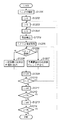
図10は、本変形例に係る画像処理装置による画像符号化アプリケーションの符号化処理の流れを示すフローチャートである。なお、同図に従ったプログラムはRAM1402にロードされており、CPU1401がこれを実行することで、図10に示したフローチャートに従った処理を行うことができる。また、図1に示す各種処理部に相当する処理は、ソフトウェア上では関数、サブルーチン等で実現することになるが、本変形例では、便宜的に、図1の各処理部の名前をそのまま使用するものとする。以下、同図を参照して、本変形例に係る画像処理装置が行う画像符号化処理の全体的な流れについて説明する。
FIG. 10 is a flowchart showing the flow of the encoding process of the image encoding application by the image processing apparatus according to this modification. Note that the program according to the figure is loaded in the
まず、装置外部から信号線208を介して予測選択信号mが入力される(ステップS1000)。続いて符号列形成部104において、予測選択信号mなど、符号化対象画像の付加情報を含めたヘッダが生成され、出力される(ステップS1001)。
First, the prediction selection signal m is input from the outside of the apparatus via the signal line 208 (step S1000). Subsequently, the code
次いで、着目する画素の垂直方向位置を保持するカウンタyを0に設定し(ステップS1002)、さらに着目する画素の水平方向位置を保持するカウンタxを0に設定する(ステップS1003)。同様に着目する成分番号を保持するカウンタCを0に設定する(ステップ1004)。 Next, a counter y that holds the vertical position of the pixel of interest is set to 0 (step S1002), and a counter x that holds the horizontal position of the pixel of interest is set to 0 (step S1003). Similarly, the counter C holding the component number of interest is set to 0 (step 1004).
信号線206から着目画素の成分値P(x,y,C)が入力され、バッファ1201に格納される。成分値P(x,y,C)は成分値予測部202、減算器203、予測誤差符号化部205により予測符号化されると同時に、近傍一致判定部101において周囲画素の同一成分値との比較が行われる(ステップS1005)。
The component value P (x, y, C) of the target pixel is input from the
着目する成分番号Cに1を加え(ステップS1006)、RGB画像の色成分の数である3と比較してC<3であればステップS1005に処理を戻し、次の成分について同様に処理を行い、そうでない場合にはステップS1014へと処理を移す。 1 is added to the component number C of interest (step S1006). If C <3 as compared with 3, which is the number of color components of the RGB image, the process returns to step S1005, and the next component is similarly processed. If not, the process proceeds to step S1014.
ステップS1014では画素一致検出部107により周辺3画素間で同一の画素値が存在するか否かを判定し、存在する場合(YES)にはステップS1008へ、存在しない場合(NO)にはステップS1009へと処理を移す。ステップS1008では近傍一致判定部101で得られるベクトル情報105を一致画素位置符号化部102で符号化する。
In step S1014, the pixel match detection unit 107 determines whether or not the same pixel value exists between the three neighboring pixels. If it exists (YES), the process proceeds to step S1008. If not (NO), the process proceeds to step S1009. Move on to In step S1008, the
ステップS1009では、近傍一致判定部101で得られる一致画素存在情報105と、画素一致検出部107からの周辺画素状態情報108、並びに、一致画素位置符号化部102からのベクトル情報の符号化データに従って、着目する画素についての符号を形成し、符号列形成部104を介して出力する(ステップS1009)。
In step S1009, according to the matching
この後、着目する画素の水平方向位置を保持するカウンタxに1を加え(ステップS1010)、画像の水平方向画素数Wと比較してx<Wであれば処理をステップS1004へと戻し、次の画素の符号化処理を行う。また、x=Wであると判断した場合には、着目する画素の垂直方向位置を保持するカウンタyに1を加える(ステップS1012)。そして、着目画素のy座標と垂直方向画素数Hと比較してy<Hであるか否かを判定する(ステップS1013)。y<Hである場合、符号化処理は未完であるとので、処理をステップS1003へと戻し、次のラインの画素について同様に処理を行う。また、y=Hである場合には、1つの画像についての符号化処理が終了したことになるので、本符号化処理を終了する。 Thereafter, 1 is added to the counter x that holds the horizontal position of the pixel of interest (step S1010). If x <W compared with the horizontal pixel count W of the image, the process returns to step S1004, and the next step The pixel is encoded. If it is determined that x = W, 1 is added to the counter y that holds the vertical position of the pixel of interest (step S1012). Then, it is determined whether or not y <H by comparing the y coordinate of the target pixel with the number of vertical pixels H (step S1013). If y <H, the encoding process is incomplete, so the process returns to step S1003, and the same process is performed for the pixels on the next line. When y = H, the encoding process for one image has been completed, and thus the present encoding process ends.
以上説明したように、ソフトウェアでもっても、上記第1の実施形態と同様の作用効果を奏することが可能になる。 As described above, even with software, it is possible to achieve the same operational effects as the first embodiment.
<第2の実施形態>
次に、上記第1の実施形態(或いはその変形例)で生成された符号化データの復号する例を第2の実施形態として説明する。復号処理は、基本的には、第1の実施形態の画像処理装置での符号化処理の逆の手順で実行すればよい。
<Second Embodiment>
Next, an example in which the encoded data generated in the first embodiment (or a modification thereof) is decoded will be described as a second embodiment. The decoding process may basically be executed in the reverse procedure of the encoding process in the image processing apparatus of the first embodiment.
図11は、本第2の実施形態に係る符号化画像データを復号する画像処理装置のブロック構成図である。 FIG. 11 is a block diagram of an image processing apparatus that decodes encoded image data according to the second embodiment.
図11に示すように、本実施形態に係る画像処理装置は、符号バッファ1101、ヘッダ解析部1102、一致画素位置復号部1103、予測誤差復号部1104、セレクタ1105、スイッチ1106、バッファ1201、成分値予測部1202、加算器1111、画素一致検出部1107とを備える。同図において1107、1108、1109、1110、1112は信号線である。
As shown in FIG. 11, the image processing apparatus according to the present embodiment includes a
以下、図11を参照して、本実施形態に係る画像処理装置が行う処理について説明する。
信号線1107を介して復号対象となる符号化データが本画像処理装置の符号バッファ1101に入力される。
Hereinafter, processing performed by the image processing apparatus according to the present embodiment will be described with reference to FIG.
The encoded data to be decoded is input to the
ヘッダ解析部1102は符号バッファ1101に格納される符号化データのヘッダ部分を解析し、予測選択信号mや、画像の水平方向/垂直方向の画素数、画素を構成する成分の数、各成分の精度などの付加情報を得る。これら付加情報は復号の過程で利用されるとするが、特に、予測選択信号mは成分値予測部202へと出力される。
The
最終的に、復号して得られた画素データは、スイッチ1106から出力されるが、この復号画素データはバッファ1201(2ライン分の復号画素データを格納する容量を有する)にも格納する。
Finally, pixel data obtained by decoding is output from the
画素一致検出部1107は第1の実施形態の画素一致検出部107と同様に、着目画素の周囲3画素(Xa、Xb、Xc)内に同一色のペアが存在するか否かを調べ、検出結果を周辺画素状態情報1112として、一致画素位置復号部1103に出力する。符号化処理と同じにするため、復号対象となる着目画素が画像の先頭ラインに位置する場合には、Xb=Xc=0として扱う。また、着目画素が各ラインの先頭位置にある場合にはXa=0として扱う。
Similar to the pixel match detection unit 107 of the first embodiment, the pixel
周辺画素状態情報1112が“1”である場合、すなわち、復号しようとしている画素Xの周辺の既復号画素データXa,Xb,Xc間に少なくとも同一色のペアがある場合、入力した符号化データ構造は、図8(b)、(c)のいずれかである。従って、一致画素位置復号部1103は、復号対象の符号化データは、ベクトル情報符の号化データであることが約束されるので、図7に示すテーブルを参照してベクトル情報1109として復号し、セレクタ1105へ出力する。このとき、復号したベクトル情報が“3”である場合、信号線1108を介して、予測誤差復号部1104及びスイッチ1106を制御する信号1108を“1”にして出力し、それ以外の場合には“0”を出力する。
When the surrounding
一方、周辺画素状態情報1112が“0”である場合には、符号化データは図8(a)の符号化データであることになる。従って、一致画素位置復号部1103では、復号処理を行なわず、信号線1108として“1”を出力する。
On the other hand, when the surrounding
予測誤差復号部1104は、一致画素位置復号部1103からの制御信号1108が“1”である場合に、ハフマンテーブル用メモリ204に格納されるハフマンテーブルを参照して、着目する画素の各成分の予測誤差を復号する。
When the control signal 1108 from the coincidence pixel
成分値予測部202では符号化時と同様にして、予測方式選択信号mによって選択された予測式を用いて着目する成分値に対する予測値pを生成し、出力する。
The component
加算器1111は成分値予測部202から出力される予測値pに、予測誤差復号部1104で復号した予測誤差eを加え、着目する成分値を復元して出力する。
The
セレクタ1105は一致画素位置復号部1103からのベクトル情報1109に従って、バッファ201から読み出される着目画素Xの周囲画素Xa、Xb、Xcの各成分値の何れかを選択して出力する。より詳しくは、ベクトル情報が“0”である場合には、セレクタ1105はXaの各成分値を選択する。また、“1”である場合にはXb、“2”である場合にはXcの各成分値を選択して出力する。なお、ベクトル情報が“3”である場合にはセレクタ1105からの出力は無効とするが、何を出力しても構わない。なぜなら、スイッチ1106ではそのデータが選択されることはないからである。
The
スイッチ1106は一致画素位置復号部1103から信号線1108が“1”の場合には、入力端子a、すなわち、予測復号して得られた画素データを選択し出力する。また、信号1108が“0”である場合には、入力端子b、すなわち、ベクトル情報に従って生成された画素データを選択し、出力する。
When the signal line 1108 from the coincidence pixel
信号線1110から復号された各画素の各成分の値が出力されるが、先に説明したように、復号結果の2ライン分の画素データは、バッファ1201にも格納され、以降の画素の復号において周囲の画素値として利用される。
Although the value of each component of each pixel decoded from the
以上の処理により、符号化データから完全に元の画像データを復元(可逆復号)することが可能になる。 Through the above processing, the original image data can be completely restored (reversible decoding) from the encoded data.
<第2の実施形態の変形例>
上記第2の実施形態は、ソフトウェアでもって実現しても構わない。その例を以下に説明する。ソフトウェアで実現する場合の装置構成は、第1の実施形態の変形例を参照した図14と同じであるのでその説明は省略し、その装置上で実行する復号アプリケーションの処理手順を図12のフローチャートに従って説明する。なお、図11に示す各種処理部に相当する処理は、ソフトウェア上では関数、サブルーチン等で実現することになるが、本変形例でも、便宜的に、図11の各処理部の名前をそのまま使用するものとする。そして、各部の処理内容は、上記第2の実施形態で説明した処理を行なうものとする。また、当然のことながら、バッファ1201や符号バッファ1103については、処理を開始するに先立って、CPU1401がRAM1402に確保することになる。
<Modification of Second Embodiment>
The second embodiment may be realized by software. An example of this will be described below. Since the apparatus configuration when realized by software is the same as that of FIG. 14 referring to the modification of the first embodiment, description thereof is omitted, and the processing procedure of the decryption application executed on the apparatus is shown in the flowchart of FIG. It explains according to. The processing corresponding to the various processing units shown in FIG. 11 is realized by functions, subroutines, etc. on the software, but in this modification as well, the names of the processing units in FIG. 11 are used as they are for convenience. It shall be. And the processing content of each part shall perform the process demonstrated in the said 2nd Embodiment. As a matter of course, the
信号線1107から復号対象となる符号化データが符号バッファに入力され、ヘッダ解析部1102で符号化データのヘッダを解析して復号に必要な付加情報(予測選択信号mや、画像の水平方向/垂直方向の画素数、画素を構成する成分の数、各成分の精度など)を取り出す(ステップS1201)。
The encoded data to be decoded is input from the
次いで、着目する画素の垂直方向位置を保持するカウンタyを0に設定し(ステップS1202)、同水平方向位置を保持するカウンタxを0に設定する(ステップS1203)。さらに、着目する成分番号を保持するカウンタCを0に設定する(ステップS1204)。 Next, a counter y that holds the vertical position of the pixel of interest is set to 0 (step S1202), and a counter x that holds the horizontal position is set to 0 (step S1203). Further, the counter C holding the component number of interest is set to 0 (step S1204).
各画素の復号では、まず、画素一致検出部107において周辺3画素間で同一の色のペアが存在するか否かを判定する。そのようなペアが存在する場合(YES)にはステップS1205へ、存在しない場合(NO)にはステップS1216へと処理を移す。 In the decoding of each pixel, first, the pixel match detection unit 107 determines whether there is a pair of the same color among the three neighboring pixels. If such a pair exists (YES), the process proceeds to step S1205. If not (NO), the process proceeds to step S1216.
ステップS1205では一致画素位置復号部1103によりベクトル情報が復号されて信号線1109から出力されるとともに、予測誤差復号部1104とスイッチ1106を制御する制御信号1108を出力する。また、ステップS1206では、復号して得られたベクトル情報が“3”であるかを判定する。この判定がYESならばステップS1207へ、NOならばステップ1208へと処理を移す。
In step S1205, the coincidence pixel
ステップS1206でYesと判定された場合(このとき信号線1108は“1”である点に注意されたい)、スイッチ1106に対して端子aを選択させる。この結果、成分値予測部202、予測誤差復号部1104、加算器1111により着目する成分値P(x,y,C)が復号され、出力する(ステップS1207)。一方、ステップS1206の判定がNoである場合(このとき信号線1108は“0”である点に注意されたい)、スイッチ1106に対して端子bを接続させる。この結果、一致画素位置復号部1103で復号した近傍一致情報に基づいてバッファ201から読み出される周辺画素の何れか1つの成分値をセレクタ1105で選択し、これを着目する画素の復号結果の成分値P(x,y,C)として出力する(ステップS1208)。
If it is determined Yes in step S1206 (note that the signal line 1108 is “1” at this time), the
ステップS1207、あるいはステップS1208で出力される成分値P(x,y,C)は信号線1110から装置外部へと出力されるとともに、バッファ201に格納される。
The component value P (x, y, C) output in step S1207 or step S1208 is output from the
ステップS1209では、着目する成分番号を保持するカウンタCに1を加え、RGB画像の色成分の数である3と比較する。C<3であればステップS1206に処理を戻し、次の成分について同様に処理を行い、そうでない場合にはステップS1211へと処理を移す。 In step S1209, 1 is added to the counter C holding the component number of interest, and compared with 3, which is the number of color components of the RGB image. If C <3, the process returns to step S1206, the same process is performed for the next component, and if not, the process proceeds to step S1211.
一方、ステップS1215の分岐によりステップS1216へと処理が移された場合、画素一致検出部107から出力される検出結果は“0”、一致画素位置復号部1103から出力される制御信号は“1”となり、スイッチ1106が端子aに接続され、成分値予測部202、予測誤差復号部1104、加算器1111により着目する成分値P(x,y,0)が復号される(ステップS1216)。
On the other hand, when the process proceeds to step S1216 due to the branch of step S1215, the detection result output from the pixel match detection unit 107 is “0”, and the control signal output from the match pixel
続いて同様に成分値予測部202、予測誤差復号部1104、加算器1111により成分値P(x,y,1)が復号され(ステップS1217)、さらに成分値P(x,y,2)が復号される(ステップS1218)。
Subsequently, similarly, the component
ステップS1211では、着目する画素の水平方向位置を保持するカウンタxに1を加え、ステップS1212でxとWとを比較し、復号した着目画素が1ラインの終端位置の画素であるか否かを判定する。x<Wである場合には、1ライン分の復号処理が未完であることになるので、処理をステップS1204へと戻し、次の画素の復号処理を行う。また、x=Wである場合には、ステップS1213に進み、着目する画素の垂直方向位置を保持するカウンタyに1を加える。 In step S1211, 1 is added to the counter x that holds the horizontal position of the pixel of interest, x is compared with W in step S1212, and it is determined whether or not the decoded pixel of interest is a pixel at the end position of one line. judge. If x <W, the decoding process for one line is incomplete, so the process returns to step S1204 to perform the decoding process for the next pixel. If x = W, the process advances to step S1213 to add 1 to the counter y that holds the vertical position of the pixel of interest.
ステップS1214では、着目画素の垂直方向座標yと画像の垂直方向の画素数Hと比較する。y<Hであれば処理をステップS1203へと戻し、次のラインの各画素について同様に処理を行い、y=Hである場合には、画像全体の復号処理が完了したことになるので、本復号処理を終了する。 In step S1214, the vertical coordinate y of the pixel of interest is compared with the number H of pixels in the vertical direction of the image. If y <H, the process returns to step S1203, and the same process is performed for each pixel of the next line. If y = H, the decoding process for the entire image has been completed. The decryption process ends.
以上の結果、第2の実施形態と同様に、可逆復号が可能になる。 As a result, lossless decoding is possible as in the second embodiment.
<第3の実施形態>
上記第1の実施形態及びその変形例では、単一の符号表を用いてベクトル情報を符号化する構成とした。この構成は、簡易である反面、冗長性が残る。また、周囲の色数が少ない場合には着目画素値と周囲画素値のいずれかが同一である可能性も高く、反対に色数が多い場合には低くなる傾向にある。そこで、第3の実施形態として、周囲画素の色数に応じて適応的にベクトル情報を符号化するか否かを切り替え、さらに色数に応じてベクトル情報の符号化方法を変更することにより、符号の冗長性を除き、さらに圧縮効率を高めることを目指す技術を説明する。
<Third Embodiment>
In the said 1st Embodiment and its modification, it was set as the structure which encodes vector information using a single code table. Although this configuration is simple, redundancy remains. In addition, when the number of surrounding colors is small, there is a high possibility that either the target pixel value and the surrounding pixel value are the same, and conversely, when the number of colors is large, the pixel value tends to be low. Therefore, as a third embodiment, by switching whether to adaptively encode vector information according to the number of colors of surrounding pixels, and further changing the encoding method of vector information according to the number of colors, A technique aimed at further improving the compression efficiency by removing the code redundancy will be described.
本第3の実施形態における画像符号化を行なう画像処理装置のブロック構成図を図13に示す。 FIG. 13 shows a block diagram of an image processing apparatus that performs image coding in the third embodiment.
図13に示すように、本第3の実施形態に係る画像データの符号化を行なう画像処理装置は、色数判定部1301、近傍一致判定部1302、一致画素位置符号化部1303、予測誤差符号化部1304、符号生成部1305、バッファ201、成分値予測部202、減算器203とを備える。同図において105、106、206、207は信号線である。なお、第1の実施形態の画像処理装置の処理部と同じ動作をする処理部については同参照番号を付し、説明を省略する。
As shown in FIG. 13, the image processing apparatus for encoding image data according to the third embodiment includes a color
以下、図13を参照して、本第3の実施形態に係る画像処理装置が行う画像符号化処理について説明する。
本実施形態に係る画像処理装置の符号化対象とする画像データは、第1の実施形態と同じとする。すなわち、RGBカラー画像データであり、各コンポーネント(色成分)8ビットで0〜255の範囲の輝度値を表現した画素データにより構成されるものとする。符号化対象の画像データの並びは点順次、即ち、ラスタースキャン順に各画素を並べ、その各画素はR、G、Bの順番でデータを並べて構成されるものとする。また、画像は水平方向W画素、垂直方向H画素により構成されるものとする。
Hereinafter, an image encoding process performed by the image processing apparatus according to the third embodiment will be described with reference to FIG.
The image data to be encoded by the image processing apparatus according to the present embodiment is the same as that of the first embodiment. That is, it is RGB color image data, and is composed of pixel data expressing luminance values in the range of 0 to 255 with 8 bits of each component (color component). The image data to be encoded is arranged in dot order, that is, in the raster scan order, and the pixels are arranged in the order of R, G, and B. The image is assumed to be composed of horizontal W pixels and vertical H pixels.
第1の実施形態の画像処理装置では装置外部から成分値予測部202で使用する予測方式を選択する予測選択信号mが入力され、これによって予測方式が切り替わる構成としたが、本第3の実施形態の画像処理装置では、成分値予測部202に設定する予測選択信号mは“4”の固定であるものとする。
In the image processing apparatus according to the first embodiment, the prediction selection signal m for selecting the prediction method used by the component
色数判定部1301は着目する画素Xの各成分について、バッファ201から図3のa,b,c、dに示す周囲4画素の同一成分値を読み出し、画素Xa、Xb、Xc、Xdを得る。着目する画素の位置を(x、y)としたとき、Xa、Xb、Xcについては先に説明したと通りである。画素Xdは、以下の通りである。
Xd=(P(x+1,y−1,0)、P(x+1,y−1,1)、P(x+1,y−1,2))
For each component of the pixel X of interest, the color
Xd = (P (x + 1, y-1, 0), P (x + 1, y-1, 1), P (x + 1, y-1, 2))
色数判定部1301は、これら画素データXa、Xb、Xc、Xdの集合中に何種類の色が存在するか検出して、その色数情報Ncを出力する。具体的には、4画素から2画素を取り出す6通りの組み合わせ、すなわち、XaとXb、XaとXc、XaとXd、XbとXc、XbとXd、XcとXdの各ペアについて一致しているか否かを判定し、一致しているペアの数をカウントする。すなわち、一致するペアの数が0であれば4色、1であれば3色、2か3であれば2色、6であれば1色と判断し、その色数を色数情報Ncとして出力する。
The color
近傍一致判定部1302は着目画素Xと同一の色を持つ画素がその周囲4画素(Xa,Xb,Xc,Xd)に存在するか否かを表す一致画素存在情報105と、ベクトル情報106を生成し、出力する。
The neighborhood
先に説明した第1の実施形態での近傍一致判定部101では周囲3画素を参照したが、本第3の実施形態では画素データXdを含めた周囲4画素との比較を行う点に注意されたい。
In the neighborhood
また、本第3の実施形態での近傍一致判定部1302、色数判定部1301から出力される色数情報Ncに依存したベクトル情報106を生成し、出力する。色数Ncの値(1乃至4)の場合に分けて近傍一致判定部1302の処理は次の通りである。
i).色数情報Ncが4である場合、即ち、Xa,Xb,Xc,Xdが全て異なる色である場合、近傍一致判定部1302は、近傍画素Xa乃至Xd内での一致不一致によらず、ベクトル情報106として“4”を出力する。
ii)色数Ncが1の場合、即ち、近傍画素Xa乃至Xdが全画素値(同一色)である場合には、着目画素XとXaを比較してX=Xaならば“0”、X≠Xaならば“1”をベクトル情報106として出力する。
iii)色数Ncが2の場合、すなわち、近傍画素Xa乃至Xd内に2種類の色が存在する場合、Xa、Xb,Xc,Xdの順番で第1画素値(色)X1と第2の画素値X2を求め、着目画素X=X1ならば“0”、X=X2ならば“1”、X≠X1かつX≠X2ならば“2”をベクトル情報106として出力する。ここで、第1、第2画素値の定義であるが、Xa、Xb,Xc,Xdの順番で見た場合、第1の画素X1は無条件でXaである。また、第2の画素値はXaと異なる値(色)を持つXb,Xc,Xdのいずれかである。例えば、Xa=Xb=Xcであり、XdがXa乃至Xcのいずれとも一致しない場合、第1画素値X1はXa、第2画素値X2はXdとなる。
iv).色数Ncが3の場合、すなわち、近傍画素Xa乃至Xd内に3種類の色が存在する場合、Xa、Xb,Xc,Xdの順番で第1の画素値X1、第2の画素値X2、第3の画素値X3を求め、X=X1ならば“0”、X=X2ならば“1”、X=X3ならば“2”、X≠X1かつX≠X2かつX≠X3ならば“3”をベクトル情報106として出力する。
Further, the
i). When the number-of-colors information Nc is 4, that is, when Xa, Xb, Xc, and Xd are all different colors, the neighborhood
ii) When the number of colors Nc is 1, that is, when the neighboring pixels Xa to Xd are all pixel values (same color), the pixel of interest X and Xa are compared, and if X = Xa, “0”, X If ≠ Xa, “1” is output as the
iii) When the number of colors Nc is 2, that is, when there are two types of colors in the neighboring pixels Xa to Xd, the first pixel value (color) X1 and the second pixel value in the order of Xa, Xb, Xc, Xd The pixel value X2 is obtained, and “0” is output as the
iv). When the number of colors Nc is 3, that is, when three types of colors exist in the neighboring pixels Xa to Xd, the first pixel value X1, the second pixel value X2, and the like in the order of Xa, Xb, Xc, Xd, The third pixel value X3 is obtained. If X = X1, “0”, X = X2 is “1”, X = X3 is “2”, X ≠ X1, X ≠ X2, and X ≠ X3 are “ 3 ″ is output as the
また、近傍一致判定部1302が一致画素存在情報105を出力する際の処理は次の通りである。
Further, the process when the neighborhood
近傍一致判定部1302は、ベクトル情報106として出力する情報と、色数判定部1301から得られる色数Ncとを比較し、両者が等しい場合には信号線105として“1”を出力し、それ以外の場合には“0”を出力する。従って、色数Nc=4である場合、一致画素存在情報105は常に“1”となる。また、色数Ncが4以外の場合であり、尚且つ、着目画素Xが周囲4画素Xa,Xb,Xc,Xdのいずれとも不一致ならば“1”、着目画素Xは少なくとも周囲4画素の何れか1つの一致する場合には“0”を出力する。
The neighborhood
一致画素位置符号化部1303では、近傍一致判定部1302からのベクトル106を符号化し、その符号化結果である符号語を符号生成部1305へ出力する。本第3の実施形態における一致画素位置符号化部1303は、色数判定部1301から出力される色数Ncによって、図15(a)乃至(c)の符号テーブルを切り替えて使用する。色数Ncが4である場合には一致画素位置符号化部1303からの符号出力は行われない。
The coincidence pixel
なお、図15(a)乃至(c)における符号語中、例えば「1(バイナリ)」はNc=1,2,3の場合に存在する。しかし、復号する装置(後述)では、着目画素の符号化データがこの符号であったとしても、既復号済みの周辺画素の色数Ncから同図(a)乃至(c)のいずれの符号であるかが特定できるので、正しく復号することが約束される。 In the code words in FIGS. 15A to 15C, for example, “1 (binary)” exists when Nc = 1, 2, 3. However, in the decoding apparatus (described later), even if the encoded data of the pixel of interest is this code, any of the codes (a) to (c) in FIG. Since it can be identified, it is promised to decode correctly.
一方、第1の実施形態と同様にして、着目画素の各成分は成分値予測部202、減算器203、予測誤差符号化部1304によって予測符号化される。本実施形態では予測選択信号mを固定値4としているので、全ての成分値に対して「a+b−c」の式により予測値を求めることになる。
On the other hand, as in the first embodiment, each component of the pixel of interest is predictively encoded by the component
なお、第1の実施形態では予測符号化部205において図6の符号表を用いたハフマン符号化を行ったが、本実施形態ではGolomb符号を用いる例について説明する。
In the first embodiment, the
Golomb符号は非負の整数値を符号化対象とし、パラメータ変数kによって異なる複数の確率モデルによる符号化が可能であるという特徴を持つ。また、Golomb符号は、符号化対象シンボルとパラメータ変数kから符号語を導出することができるため、符号表が不要という利点がある。Golomb符号の一形態がISOとITU-Tから国際標準勧告されるJPEG-LS(ISO/IEC 14495−1|ITU-T Recommendation T.87)において予測誤差の符号化方式として採用されている。ここでは減算器203から出力される予測誤差eを次式により非負の整数値(Vとする)に変換した後に,これを選択したkパラメータでGolomb符号化する。
e≧0の場合、V=2×e
e<0の場合、V=−2×e−1
The Golomb code has a feature that a non-negative integer value can be encoded, and encoding can be performed using a plurality of probability models that differ depending on the parameter variable k. In addition, the Golomb code has an advantage that a code table is unnecessary because a code word can be derived from a symbol to be encoded and a parameter variable k. One form of Golomb code is adopted as a prediction error encoding method in JPEG-LS (ISO / IEC 14495-1 | ITU-T Recommendation T.87), which is an international standard recommendation from ISO and ITU-T. Here, the prediction error e output from the
When e ≧ 0, V = 2 × e
When e <0, V = −2 × e−1
符号化対象の非負の整数値Vを符号化パラメータkでGolomb符号化する手順は次の通りである。 The procedure for Golomb encoding the non-negative integer value V to be encoded with the encoding parameter k is as follows.
まず、Vをkビット右シフトして整数値mを求める。Vに対する符号はm個の「0」に続く「1」(可変長部)とVの下位kビット(固定長部)の組み合わせにて構成する。図16にk=0、1、2におけるGolomb符号の例を示しておく。ここに述べた符号の構成方法は一例であり、固定長部と可変長部の順序が逆にしても一意復号可能な符号を構成することができる。また、0と1を反対にして符号を構成することもできる。符号化パラメータkの選択方法としては所定の単位で最適なkパラメータの選択して符号列に含める方法など様々な手法が考えられるが、本実施形態ではJPEG−LSと同様の手法により符号化の過程で更新していく方法を用いる。以下、符号化パラメータkの選択方法について述べる。 First, V is shifted right by k bits to obtain an integer value m. The code for V is composed of a combination of “1” (variable length portion) following m “0” and lower k bits (fixed length portion) of V. FIG. 16 shows an example of Golomb codes at k = 0, 1, and 2. The code configuration method described here is merely an example, and a uniquely decodable code can be configured even if the order of the fixed-length part and the variable-length part is reversed. Also, the code can be configured by reversing 0 and 1. Various methods such as a method of selecting an optimal k parameter in a predetermined unit and including it in the code string can be considered as a method of selecting the encoding parameter k. In this embodiment, encoding is performed by a method similar to JPEG-LS. Use a method of updating in the process. Hereinafter, a method for selecting the encoding parameter k will be described.
予測誤差符号化部1304には、符号化済みの画素の数を保持するカウンタNと、各成分毎に符号化済みの予測誤差の絶対値の合計を保持するカウンタA[C](Cは成分番号であり、0〜2)を備える。符号化の開始時点でカウンタNに1を、カウンタA[0]〜A[2]に2を設定する。符号化対象の成分値ごとにN×2^k(x^yはxのy乗を意味する)がA[C]を超えない最大のkを求め、これを用いて先に説明した手順にて予測誤差eをGolomb符号化し、符号語を出力する。近傍一致判定部1302からの情報105が“1”である場合(着目画素Xと同一色が近傍画素a,b,c,dに存在しない場合)には、各成分の符号化処理後にA[C]に予測誤差の絶対値|e|を加算して更新する。またこの場合、全成分の符号化処理後に変数Nに1を加えて更新する。なお、A[C]とNを所定の範囲内に限定するためにはNが一定値(例えば32)に達したタイミングでA[C]とNを1/2にするといった処理を適用すれば良い。
The prediction
符号生成部1305は、一致画素存在情報105に従って、一致画素位置符号化部1303から出力される符号語と予測誤差符号化部1304から出力される各成分の予測符号化データから着目する画素に対する符号化データを生成する。一致画素存在情報105が“0”である場合には、図8(b)のように一致画素位置符号化部1303から出力される符号語のみを着目画素の符号化データとする。一方、一致画素存在情報105が“1”である場合には同図(c)のように一致画素位置符号化部1303から出力される符号語に、予測誤差符号化部1304から出力される各成分値の予測符号化データを連結させて着目画素の符号化データとする。なお、色数判定部1301により検出された色数Ncが4であった場合には一致画素位置符号化部1303から出力される符号語は無い(即ち、近傍一致情報の符号語長は0である)点に注意されたい。
In accordance with the matching
符号列形成部104では予測選択信号mや、画像の水平方向/垂直方向の画素数、画素を構成する成分の数、各成分の精度などの付加情報と、符号生成部1305から出力される符号化データから、所定のフォーマットの符号列を形成し、信号線207に出力する。本第3の実施形態においても第1の実施形態と同様に図9に示す構成の符号列を生成することができる。なお、本第3の実施形態の画像処理装置では予測選択信号mを固定値としている。従って、復号側装置での予測選択信号mも固定するとするなら、ヘッダには予測選択信号mを格納する必要はない。
In the code
以上の説明のように、本第3の実施形態に係る画像処理装置では、符号化対象となる画素Xの周囲にある符号化済みの画素Xa,Xb,Xc,Xdの色数に応じてベクトル情報の符号語の有無、および、ベクトル情報の符号化における符号の割り当てを変更している。これにより、文字、線画、CG画像など、着目画素の周囲に同じ色の画素が存在する可能性の高い画像データの可逆圧縮性能を更に向上させるとともに、自然画像など、着目画素の周囲に同じ色の画素が存在する可能性の低い画像データにおいても余分な付加を発生することなく、効率的な符号化を行うことができる。 As described above, in the image processing apparatus according to the third embodiment, a vector corresponding to the number of encoded pixels Xa, Xb, Xc, and Xd around the pixel X to be encoded is used. The presence / absence of an information codeword and the code assignment in vector information encoding are changed. This further improves the reversible compression performance of image data that is likely to have pixels of the same color around the pixel of interest, such as characters, line drawings, and CG images, and the same color around the pixel of interest, such as a natural image. It is possible to perform efficient encoding without generating extra addition even in image data in which there is a low possibility of the presence of pixels.
<第3の実施形態の変形例>
上記第3の実施形態をソフトウェアでもって実現しても構わない。その例を以下に説明する。ソフトウェアで実現する場合の装置構成は、第1の実施形態の変形例を参照した図14と同じであるのでその説明は省略し、その装置上で実行する符号化アプリケーションの処理手順を説明する。
<Modification of Third Embodiment>
The third embodiment may be realized by software. An example of this will be described below. Since the apparatus configuration when implemented by software is the same as that of FIG. 14 with reference to the modification of the first embodiment, the description thereof will be omitted, and the processing procedure of the encoding application executed on the apparatus will be described.
本第3の実施形態における符号化処理手順を図22に示す。図示の様に、先に説明した第1の実施形態おける符号化処理の流れとして示した図10のフローチャートとほぼ同様の流れにになるので、同処理については同符号を付した。異なる点としては図10でのステップS1000に示した予測選択信号mの入力が不要となり、ステップS1015における色数判定部1301による色数Ncを求める処理が追加された点である。以下、本第3の実施形態の変形例を説明する。なお、各種バッファについては、処理を開始するに先立って、CPU1401がRAM1402に確保することになる。
The encoding processing procedure in the third embodiment is shown in FIG. As shown in the figure, the flow is substantially the same as the flowchart of FIG. 10 shown as the flow of the encoding process in the first embodiment described above, and thus the same reference numerals are given to the same processes. The difference is that the input of the prediction selection signal m shown in step S1000 in FIG. 10 is not necessary, and a process of obtaining the color number Nc by the color
まず、符号列形成部104において、符号化対象画像の付加情報を含めたヘッダが生成され、出力される(ステップS1001)。次いで、着目する画素の垂直方向位置を保持するカウンタyを0に設定し(ステップS1002)、さらに着目する画素の水平方向位置を保持するカウンタxを0に設定する(ステップS1003)。同様に着目する成分番号を保持するカウンタCを0に設定する(ステップS1004)。
First, the code
信号線206から着目画素の成分値P(x,y,C)を入力し、バッファ201に格納する。成分値P(x,y,C)は成分値予測部202、減算器203、予測誤差符号化部1304により予測符号化されると同時に、近傍一致判定部1302において周囲画素の同一成分値との比較が行われる(ステップS1005)。着目する成分番号Cに1を加え(ステップS1006)、RGB画像の色成分の数である3と比較してC<3であればステップS1005に処理を戻し、次の成分について同様に処理を行い、そうでない場合にはステップS1008へと処理を移す。
The component value P (x, y, C) of the target pixel is input from the
着目画素について全ての成分が入力されると色数判定部1301において色数Ncが求められる(ステップS1015)。これを用いて近傍一致判定部1302はベクトル情報106と一致画素存在情報105を生成する。但し、Ncが4である場合にはベクトル情報の符号化は行われない(ステップS1008)。
When all the components are input for the pixel of interest, the color
一致画素位置符号化部1303から出力される近傍一致情報の符号語と、予測誤差符号化部1304から出力される各成分の予測符号化データに基づき、符号生成部1305に対して、一致画素存在情報105に従って着目する画素についての符号を形成を生成させ、その結果を符号列形成部104を介して出力させる(ステップS1009)。
Based on the code word of the neighborhood matching information output from the matching pixel
次いで、着目する画素の水平方向位置を保持するカウンタxに1を加え(ステップS1010)、画像の水平方向画素数Wと比較してx<Wであれば処理をステップS1004へと戻し、次の画素の符号化処理を行う。また、x=Wである場合には、ステップS1012へと処理を進め、着目する画素の垂直方向位置を保持するカウンタyに1を加える。そそて、着目画素の垂直方向の位置を示すyと画像の垂直方向画素数Hと比較してy<Hであれば処理をステップS1003へと戻し、次のラインの画素について同様に処理を行。また、y=Hである場合には、画像全体に対する符号化が完了したことになるので、本符号化処理を終了する。 Next, 1 is added to the counter x that holds the horizontal position of the pixel of interest (step S1010). If x <W compared to the horizontal pixel count W of the image, the process returns to step S1004, and the next step Pixel encoding processing is performed. If x = W, the process advances to step S1012 to add 1 to the counter y that holds the vertical position of the pixel of interest. Therefore, if y <H compared with y indicating the vertical position of the pixel of interest and the number H of vertical pixels in the image, the process returns to step S1003, and the same process is performed for the pixels on the next line. . If y = H, the encoding for the entire image is complete, and the encoding process is terminated.
以上の説明のように、本変形例によっても第3の実施形態と同様の作用効果を奏することが可能になる。 As described above, this modification can also provide the same operational effects as those of the third embodiment.
[第4の実施形態]
次に、上記第3の実施形態及びその変形例にて生成された符号化画像データを復号する例を第4の実施形態として説明する。基本的には、上記第3の実施形態の符号化処理の逆の手順で処理を行なえばよい。
[Fourth Embodiment]
Next, an example of decoding the encoded image data generated in the third embodiment and its modification will be described as a fourth embodiment. Basically, the process may be performed in the reverse order of the encoding process of the third embodiment.
図17は、本第4の実施形態に係る画像データの復号を行なう画像処理装置の機能構成を示すブロック図である。図17に示すように、本実施形態に係る画像処理装置は、一致画素位置復号部1701、予測誤差復号部1702、セレクタ1703、色数判定部1301、符号バッファ1101、ヘッダ解析部1102、スイッチ1106、バッファ201、成分値予測部202、加算器1111とを備える。同図において1107、1108、1109、1110は信号線である。第1から第3の実施形態の画像処理装置の処理ブロックと同じ動作をするブロックについては同じ参照符号を付し、説明を省略する。
FIG. 17 is a block diagram illustrating a functional configuration of an image processing apparatus that decodes image data according to the fourth embodiment. As shown in FIG. 17, the image processing apparatus according to the present embodiment includes a matching pixel
以下、図17を参照して、本第4の実施形態に係る画像処理装置が行う処理について、第2の実施形態で説明した画像処理装置との差異を説明する。
第2の実施形態と同様に、復号対象となる符号化データが信号線1107を介して本画像処理装置に入力され、符号バッファ1101に適宜格納され、ヘッダ解析部1102により付加情報の取得が行われる。
Hereinafter, with reference to FIG. 17, the difference between the processing performed by the image processing apparatus according to the fourth embodiment and the image processing apparatus described in the second embodiment will be described.
As in the second embodiment, the encoded data to be decoded is input to the image processing apparatus via the
本第4の実施形態でも、最終的に復号して得られた画素データは、スイッチ1106より出力されるが、そのうちの2ライン分の画像データはバッファ201に格納される(復号処理を開始する際に零クリアされている)。
Also in the fourth embodiment, the pixel data finally obtained by decoding is output from the
色数判定部1301では第3の実施形態で説明した処理により、着目画素の近傍画素a,b,c,d内の色数Ncを求めて出力する。
The number-of-
一致画素位置復号部1701は、色数判定部1301から出力される色数Ncが1から3である場合に、各画素の符号化データについて、まず、図15(a)乃至(c)のいずれのテーブルを利用するかを決定し、符号語からベクトル情報に復号する。復号したベクトル情報は、信号線1109を介してセレクタ1703へ出力する。
When the number of colors Nc output from the number-of-
また、一致画素位置復号部1701は、復号したベクトル情報と色数Ncを比較して、両者が等しい場合、予測誤差復号部1702とスイッチ1106を制御する信号1108として“1”を出力し、異なる場合には“0”を出力する。一方、色数Ncが4である場合には信号線1108から制御信号“1”を出力し、ベクトル情報として信号線1109に“4”を出力する。
Also, the coincidence pixel
予測誤差復号部1702は、一致画素位置復号部1701からの制御信号1108が“1”である場合に、第3の実施形態で説明した予測誤差符号化部1304の符号化処理と対をなす復号手順により着目する画素の各成分の予測誤差を復号する。この予測誤差復号部1702には、予測誤差符号化部1304と同様、符号化済みの画素の数を保持するカウンタNと、各成分毎に符号化済みの予測誤差の絶対値の合計を保持するカウンタA[C](Cは成分番号であり、0〜2)とを備え、復号の開始時点でカウンタNを1に、カウンタA[0]〜A[2]を2に設定する。着目画素の着目する成分値の復号においては符号化時と同様の方法により、NとA[0]〜A[2]から符号化時に用いたkパラメータと同じ値を導出し、これを用いて非負の整数値Vを復号する。Golomb符号の復号は符号化と逆の手順で行われ、まず、復号開始点から「0」の連続数を調べ、整数値mに保持する。「0」の連続を終端させた「1」のすぐ後からkビット取り出し、mをkビット左シフトした後、取り出したkビットとのOR演算を行うことにより非負の整数値Vを復号する。この非負の整数値Vから以下の演算により予測誤差eを復号する。
Vが奇数の場合、e=−(V+1)/2
Vが偶数の場合、e=V/2
第2の実施形態と同様にして成分値予測部202は予測値pを生成し、加算器1111で、予測値pと上記予測誤差eとを加算することで、着目画素の着目色成分を復元して出力する。各成分の復号後、カウンタN[C]に復号した予測誤差の絶対値|e|を加算して更新し、着目する画素について全成分の復号が終了した時点でカウンタNに1を加えて更新する。なお、A[C]とNを所定の範囲内に限定するためにはNが一定値(例えば32)に達したタイミングでA[C]とNを1/2にするといった処理を適用すれば良い。但し、同じkパラメータを得るためには、この処理は符号化側と復号側で共通に行わなければならない。
When the control signal 1108 from the matching pixel
When V is an odd number, e = − (V + 1) / 2
When V is an even number, e = V / 2
Similar to the second embodiment, the component
セレクタ1703は一致画素位置復号部1701からのベクトル情報1109に従って、バッファ201から読み出される着目画素Xの周囲画素Xa、Xb、Xc、Xdの各成分値の何れかを選択して出力する。すなわち、ベクトル情報1109が“0”である場合には、Xaの各成分値を選択し、“1”である場合にはXa,Xb,Xc,Xdの順番に見てXaとは異なる第2の画素値(色)を持つ画素の各成分値を選択する。同様に“2”である場合にはXa,Xb,Xc,Xdの順番で見て、第1の画素値(Xa)および第2の画素値と異なる第3の画素値の各成分値を選択して出力する。なお、ベクトル情報1109が“3”、または“4”である場合、セレクタ1703からの出力は無効である。なお、この場合、スイッチ1106が端子a側に接続されることになるので、セレクタ1703からの出力は何であっても構わない。
The
スイッチ1106は一致画素位置復号部1701から信号線1108が“1”である場合には端子aを選択して予測復号して得られた画素データを出力する。また、信号1108が“0”である場合には端子bを選択し、ベクトル情報に基づいて得られた画素データを復号結果として出力する。スイッチ1106から出力された画素データは、先に説明したように、バッファ1201に格納され、後続して入力する符号化データを復号する際の周囲画素として利用される。
When the signal line 1108 is “1” from the matching pixel
以上の説明したように、符号化データから完全に元の画像データを復元することができる。 As described above, the original image data can be completely restored from the encoded data.
<第4の実施形態の変形例>
上記第3の実施形態は、ソフトウェアでもって実現しても構わない。その例を以下に説明する。
<Modification of Fourth Embodiment>
The third embodiment may be realized by software. An example of this will be described below.
なお、図17に示す各種処理部に相当する処理は、ソフトウェア上では関数、サブルーチン等で実現することになるが、本変形例でも、便宜的に、図17の各処理部の名前をそのまま使用するものとする。装置構成は、図14と同じであるので、その説明は省略し、その装置上で実行する復号アプリケーションの処理手順を図23のフローチャートに従って説明する。 Note that the processes corresponding to the various processing units shown in FIG. 17 are realized by functions, subroutines, etc. on the software, but in this modification as well, the names of the respective processing units in FIG. 17 are used as they are for convenience. It shall be. Since the apparatus configuration is the same as in FIG. 14, the description thereof is omitted, and the processing procedure of the decryption application executed on the apparatus will be described with reference to the flowchart of FIG.
図23に示すように、第2の実施形態の復号処理の流れとして説明した図12のフローチャートとほぼ同様の処理手順で行われる。それ故、図12のフローチャートと同じ処理については同参照符号を示す。また、特に異なる点としては、ステップS1219の色数Ncを検出する処理が追加され、ステップS1205では色数Ncに応じてベクトル情報を復号する点と、ステップS1206に代わって、ステップS1220で復号して得られたベクトル情報と色数Ncが等しいかどうかを判定することである。なお、同図に従ったプログラムはRAM1402にロードされており、CPU1401がこれを実行することになる。
As shown in FIG. 23, the processing procedure is almost the same as the flowchart of FIG. 12 described as the flow of the decoding processing of the second embodiment. Therefore, the same processes as those in the flowchart of FIG. Further, as a particularly different point, a process for detecting the number of colors Nc in step S1219 is added. In step S1205, vector information is decoded according to the number of colors Nc, and in step S1206, decoding is performed in step S1220. It is determined whether or not the vector information obtained in this way and the number of colors Nc are equal. Note that the program according to the figure is loaded in the
先ず、信号線1107から復号対象となる符号化データを符号バッファ1101に格納し、ヘッダ解析部1102で符号化データのヘッダを解析して復号に必要な付加情報を取り出す(ステップS1201)。着目する画素の垂直方向位置を保持するカウンタyを0に設定し(ステップS1202)、同水平方向位置を保持するカウンタxを0に設定する(ステップS1203)。さらに、着目する成分番号を保持するカウンタCを0に設定する(ステップS1204)。
First, encoded data to be decoded is stored in the
各画素の復号では、まず、色数判定部1301により周囲画素の色数Ncを求め、Ncの値に応じたベクトル情報1109を一致画素位置復号部1701で復号させる。また、このとき、一致画素存在情報1108も生成し、予測誤差復号部1702とスイッチ1106に制御信号として出力する(ステップS1205)。
In decoding each pixel, first, the color
次に、復号して得られたベクトル情報と色数Ncと等しいか否かを判定し(ステップS1220)、等しい(YES)ならばステップS1207へ、等しくない(NO)ならばステップS1208へと処理を移す。 Next, it is determined whether or not the vector information obtained by decoding is equal to the number of colors Nc (step S1220). If they are equal (YES), the process proceeds to step S1207, and if they are not equal (NO), the process proceeds to step S1208. Move.
ステップS1207に処理が移った場合(このとき信号線1108は“1”)、スイッチ1106の端子aを選択し、成分値予測部202、予測誤差復号部1702、加算器1111により着目する成分値P(x,y,C)が復号する。一方、ステップS1220でNOと判定した場合(このとき信号線1108は“0”)、処理はステップS1208に進み、スイッチ1106の端子bを選択し、一致画素位置復号部1701で復号したベクトル情報に基づいてバッファ1201から読み出される周辺画素の何れか1つの成分値をセレクタ1703で選択させ、この結果を、着目する画素の成分値P(x,y,C)として出力する。このようにして、ステップS1207、あるいはステップS1208で出力される成分値P(x,y,C)は信号線1110から装置外部へと出力されるとともに、バッファ201に格納される。
When the process moves to step S1207 (at this time, the signal line 1108 is “1”), the terminal a of the
ステップS1209では着目する成分番号を保持するカウンタCに1を加え、RGB画像の色成分の数である3と比較してC<3であればステップS1206に処理を戻り、次の成分について復号処理を行なう。また、C=3であると判断した場合には、ステップS1211へと処理を移し、着目する画素の水平方向位置を保持するカウンタxに1を加える。そして、ステップS1212で、x<Wであれると判断した場合には、ステップS1204へと戻し、次の画素の復号処理を行う。また、x=Wであると判断した場合には、ステップS1213へ処理を移し、着目する画素の垂直方向位置を保持するカウンタyに1を加える。次いで、画像の垂直方向画素数Hと比較してy<Hであれば処理をステップS1203へと戻り、次のラインの各画素について同様に処理を行う。また。y=Hであると判断した場合には、画像全体に対する復号処理が完了したことを意味するので、本復号処理を終了する。 In step S1209, 1 is added to the counter C that holds the component number of interest, and if C <3 as compared with 3, which is the number of color components of the RGB image, the process returns to step S1206 to decode the next component. To do. If it is determined that C = 3, the process proceeds to step S1211, and 1 is added to the counter x that holds the horizontal position of the pixel of interest. If it is determined in step S1212 that x <W, the process returns to step S1204, and the next pixel is decoded. If it is determined that x = W, the process proceeds to step S1213, and 1 is added to the counter y that holds the vertical position of the pixel of interest. Next, if y <H compared with the number H of vertical pixels of the image, the process returns to step S1203, and the same process is performed for each pixel of the next line. Also. If it is determined that y = H, it means that the decoding process for the entire image has been completed, and thus this decoding process ends.
以上の動作により、符号化データから完全に元の画像データを復元することができることになる。 With the above operation, the original image data can be completely restored from the encoded data.
<第5の実施形態>
第3の実施形態の画像処理装置では、着目画素に対して、符号化済みの周囲画素群の色数に応じてベクトル情報の符号化を行うか否か、及び、符号化する際のテーブルを切り替えた。これにより、自然画像など、着目画素値と同一の画素値(色)を持つ周囲画素が存在する可能性の低い画像に対しても、ベクトル情報の符号化による符号量の増加を抑制することができた。また、着目画素値と同一の画素値(色)を持つ近傍画素が存在する可能性の高いコンピュータグラフィックスの画像等については、更なる圧縮効率が期待できるものであった。更なる圧縮率を実現するためには、ランレングス符号化と組み合わせることも効果的である。そこで、本第5の実施形態として、第3の実施形態にランレングス符号化を組み合わせた例について説明する。
<Fifth Embodiment>
In the image processing apparatus according to the third embodiment, whether or not to encode vector information according to the number of colors of the encoded surrounding pixel group for the pixel of interest, and a table for encoding are displayed. Switched. As a result, an increase in the amount of code due to encoding of vector information can be suppressed even for an image that is unlikely to have surrounding pixels having the same pixel value (color) as the target pixel value, such as a natural image. did it. Further, for computer graphics images and the like that are likely to have neighboring pixels having the same pixel value (color) as the target pixel value, further compression efficiency can be expected. In order to realize a further compression rate, it is also effective to combine with run length coding. Therefore, as the fifth embodiment, an example in which run-length encoding is combined with the third embodiment will be described.
図18は本第5の実施形態に係る画像符号化を行なう画像処理装置の機能構成を示すブロック図である。図18に示すように、本第5の実施形態に係る画像処理装置は、ランレングス符号化部1801、スイッチ1802、色数判定部1301、近傍一致情報符号化部1306、成分値予測符号化部1307、符号生成部1305、バッファ201、符号列形成部104から構成される。なお、105、206、207は信号線である。第1の実施形態の画像処理装置の処理ブロックと同じ動作をするブロックについては同じ番号を付し、説明を省略する。
FIG. 18 is a block diagram showing a functional configuration of an image processing apparatus that performs image coding according to the fifth embodiment. As illustrated in FIG. 18, the image processing apparatus according to the fifth embodiment includes a run
以下、図18を参照して、本第5の実施形態に係る画像処理装置における画像符号化処理について説明する。 Hereinafter, with reference to FIG. 18, an image encoding process in the image processing apparatus according to the fifth embodiment will be described.
本第5の実施形態の画像処理装置は、図13に示した第3の実施形態の画像処理装置に、ランレングス符号化部1801、スイッチ1802を追加した構成と成っている。近傍一致情報符号化部1306は、図13において近傍一致判定部1302と一致画素位置符号化部1303を内部に含む破線部分を一纏めにしたものであり、また、成分値予測符号化部1307は同図の成分値予測部202、減算器203、予測誤差符号化部1304を含む破線部分を一纏めにしたものである。
The image processing apparatus of the fifth embodiment has a configuration in which a run-
また、本第5の実施形態では、符号化対象とする画像データは、CMYKカラー画像データであり、各コンポーネント(色成分)8ビットで0〜255の範囲の濃度値を表現した画素データにより構成されるものとする。符号化対象の画像データの並びは点順次、即ち、ラスタースキャン順に各画素を並べ、その各画素はC,M,Y,Kの順番でデータを並べて構成されるものとする。また、画像は水平方向W画素、垂直方向H画素により構成されるものとする。なお、色空間としてC(シアン)M(マゼンタ)Y(イエロー)K(ブラック)にしたのは、これまでの実施形態では符号化対象画像がRGBカラー画像データであり、それ以外の一例を示すためのものである。 In the fifth embodiment, the image data to be encoded is CMYK color image data, and is composed of pixel data expressing a density value in the range of 0 to 255 with 8 bits of each component (color component). Shall be. Assume that the image data to be encoded is arranged in the order of dots, that is, in the raster scan order, and the pixels are arranged in the order of C, M, Y, and K. The image is assumed to be composed of horizontal W pixels and vertical H pixels. Note that C (cyan), M (magenta), Y (yellow), and K (black) are used as the color space in the embodiments so far, the encoding target image is RGB color image data, and other examples are shown. Is for.
次に、本第5の実施形態の画像処理装置での各部の動作について説明する。先に説明した第3の実施形態と同じく、成分値予測部202(成分値予測符号化部1307の内部)で用いる予測方式は固定であるとし、常に予測選択信号m=4が入力されているものとする。 Next, the operation of each unit in the image processing apparatus according to the fifth embodiment will be described. As in the third embodiment described above, the prediction method used in the component value prediction unit 202 (inside the component value prediction encoding unit 1307) is assumed to be fixed, and the prediction selection signal m = 4 is always input. Shall.
符号化対象画像データは信号線206から順に入力される。画素データの入力順序はラスタースキャン順とし、各画素でC,M,Y,Kの順番で成分データが入力される。画素の各成分の濃度値は、C,M,Y,Kをそれぞれ成分番号0,1,2,3と定義し、画像の左上隅を座標(0,0)として水平方向画素位置x、垂直方向画素位置yにある画素の成分番号Cの値をP(x,y,C)と表す。例えば、水平方向画素位置104、垂直方向画素位置335の画素のC,M,Y,K各成分の値はそれぞれP(104,335,0)、P(104,335,1)、P(104,335,2)、P(104,335,3)と表す。また、成分のまとまりとして画素値を表現する場合にはC,M,Y,Kの各成分値を要素とするベクトルXとして表現する。例えば、C,M,Y,K各成分の値がc、m、y、kである画素についてはX=(c、m、y、k)と記述する。
The encoding target image data is sequentially input from the
本画像処理装置では、基本的には信号線206から順次入力される画像データの1画素ごとに、符号列形成部104から対応する符号が出力されるが、ランレングス符号化が適用される部分では画素のラン(連続数)に対して符号が出力される。
In this image processing apparatus, a code corresponding to the run length encoding is basically output from the code
バッファ201は画像データを2ライン分格納する領域を持ち、信号線206から入力される画像データを順次格納していく。先に述べたように、画像データは各画素がラスター順に、そして各画素ではC,M,Y,Kの順番で成分値が入力されるが、バッファ201からは、図3のa,b,c,dに示す周囲3画素の同一成分値が読み出され、色数判定部1301、近傍一致情報符号化部1306、成分値予測符号化部1307へと供給される。着目する画素の成分値をP(x,y,C)とするとき、a=P(x−1,y,C)、b=P(x,y−1、C)、c=P(x−1,y−1,C)、d=P(x+1,y+1,C)である。なお、画像の最初のラインや各ラインの先頭/末尾などで、a,b,c,dが画像の外側となる場合には符号化側と復号側で共通の値を仮定する。本実施形態では0とする。
The
色数判定部1301は着目する画素Xの各成分について、バッファ201から図3のa,b,c、dに示す周囲4画素の同一成分値を読み出し、画素Xa,Xb,Xc,Xdを得る。着目する画素の位置を(x、y)とし、これを用いてXa,Xb,Xc,Xdを表現すると以下の通りである。
Xa= (P(x-1,y,0), P(x-1,y,1), P(x-1,y,2), P(x-1,y,3))
Xb= (P(x,y-1,0), P(x,y-1,1), P(x,y-1,2), P(x,y-1,3))
Xc= (P(x-1,y-1,0), P(x-1,y-1,1), P(x-1,y-1,2), P(x-1,y-1,3))
Xd= (P(x+1,y-1,0), P(x+1,y-1,1), P(x+1,y-1,2), P(x+1,y-1,3))
For each component of the pixel X of interest, the color
Xa = (P (x-1, y, 0), P (x-1, y, 1), P (x-1, y, 2), P (x-1, y, 3))
Xb = (P (x, y-1,0), P (x, y-1,1), P (x, y-1,2), P (x, y-1,3))
Xc = (P (x-1, y-1,0), P (x-1, y-1,1), P (x-1, y-1,2), P (x-1, y- 1,3))
Xd = (P (x + 1, y-1,0), P (x + 1, y-1,1), P (x + 1, y-1,2), P (x + 1, y- 1,3))
色数判定部1301は、これらXa,Xb,Xc,Xdの集合中に何種類の色が存在するかを検出して、その色数Ncを出力する。具体的には4画素から2画素を取り出す6通りの組み合わせについて、取り出した2画素が同一である数をカウントし、0であれば4色、1であれば3色、2か3であれば2色、6であれば1色と判断し、その色数Ncを出力する。これは第3の実施形態と同じである。
The number-of-
近傍一致情報符号化部1306は色数判定部1301から出力される周囲4画素の色数Ncが1から3の場合に、第3の実施形態と同様にして、着目画素Xとその周囲4画素(Xa,Xb,Xc,Xd)との一致/不一致、及び、一致する場合の近傍画素を特定するベクトル情報を符号化し、その符号語を出力する。また、信号線105には周囲4画素に同一色を持つペアが存在するか否かを表す周辺画素状態情報を出力する。
When the number of colors Nc of the surrounding four pixels output from the color
一方、第3の実施形態と同様にして、着目画素のC,M,Y,Kの各成分が成分値予測符号化部1307により符号される。なお、成分値予測符号化部1307における各成分の予測符号化には国際標準方式JPEG−LSにおけるregular modeの符号化手法などを適用しても良い。
On the other hand, as in the third embodiment, the C, M, Y, and K components of the pixel of interest are encoded by the component value
符号生成部1305は、信号線105の周辺画素状態情報に従って、近傍一致情報符号化部1306から出力されるベクトル情報の符号語と成分値予測符号化部1307から出力される各成分の予測符号化データから、着目する画素に対する符号化データを生成する。符号生成部1305の動作は第3の実施形態で説明の通りである。
The
ランレングス符号化部1801は内部に同じ画素値の連続数を計測するカウンタRLを保持し、色数判定部1301から出力される色数Ncが1になった場合に計測を開始及び継続する。但し、着目する画素Xが直前の画素値Xaと異なる値となるか、1ラインの最後の画素に到達した場合には、それまでのカウンタRLに保持されているランレングスを符号化して出力する。ランレングスの符号化には、例えば、様々な方法を適用することが可能であるが、ここでは国際標準方式JPEG−LSにおけるrun modeによるランレングスの符号化と同じ手法を用いることとし、詳細については省略する。なお、ここでは説明を簡単にするために色数判定部1301から出力される色数Ncに基づいて画素の連続数を計測開始するものとして説明したが、符号化側と復号側で同様にラン(画素値の連続)の発生が予想できる条件であれば良い。例えば、Xaの直前の画素をXeとしてXa=Xeである場合にランの計測を開始するといった方法を用いても良い。
The run-
スイッチ1802は色数判定部1301から出力される色数Ncが1である場合に端子b側に接続し、ランレングス符号化部1801によりランレングスのカウントが行われている間はb側に固定する。ランレングスが終端し、ランレングス符号化部1801から符号が出力された後、端子aに切り替える。
The
以上の説明のように、本第5の実施形態に係る画像処理装置では、近傍一致情報符号化部1306、成分値予測符号化部1307、ランレングス符号化部1801を備えて、符号化対象となる画素Xの周囲にある符号化済みの画素Xa,Xb,Xc,Xdの色数に応じてこれらの符号化方式を選択的に動作させて符号化を行っている。これらの選択は符号化済みの画素によって行われるため、符号化方式の切り替えのための情報を伝送する必要はない。第3の実施形態と同様の効果に加えて、ランレングス符号化を導入することで、文字、線画、CG画像など可逆圧縮性能を更に向上させることができる。
As described above, the image processing apparatus according to the fifth embodiment includes the neighborhood match
<第5の実施形態の変形例>
上記第5の実施形態をソフトウェアでもって実現しても構わない。その例を以下に説明する。ソフトウェアで実現する場合の装置構成は、第1の実施形態の変形例を参照した図14と同じであるのでその説明は省略し、その装置上で実行する符号化アプリケーションの処理手順を説明する。
<Modification of Fifth Embodiment>
The fifth embodiment may be realized by software. An example of this will be described below. Since the apparatus configuration when implemented by software is the same as that of FIG. 14 with reference to the modification of the first embodiment, the description thereof will be omitted, and the processing procedure of the encoding application executed on the apparatus will be described.
本第5の実施形態における符号化処理手順を図19のフローチャートに示す。図19は本実施形態の画像処理装置による符号化処理の流れを示すフローチャートである。なお、同図に従ったプログラムはRAM1402にロードされており、CPU1401がこれを実行するものである。ソフトウェアでもって実現する場合、図18に示した各処理部に相当する処理は、ソフトウェア上では関数、サブルーチン等で実現するが、本変形例でも、便宜的に、図11の各処理部の名前をそのまま使用する。
An encoding process procedure according to the fifth embodiment is shown in a flowchart of FIG. FIG. 19 is a flowchart showing the flow of encoding processing by the image processing apparatus of this embodiment. The program according to the figure is loaded into the
まず、符号列形成部104において、符号化対象画像の付加情報を含めたヘッダが生成され、出力される(ステップS1901)。次いで、着目する画素の垂直方向位置を保持するカウンタyを0に設定し、ランレングス符号化部1801の内部に保持されるカウンタRLを0に設定する(ステップS1902)。さらに着目する画素の水平方向位置を保持するカウンタxを0に設定する(ステップS1903)。
First, the code
次に、座標(x、y)座標に位置する着目画素Xの周辺の4画素について、色数判定部1301により色数Ncを求める(ステップS1904)。色数Ncが1、もしくはカウンタRLが0以外の値である場合(YES)にはステップS1914へと処理を移し、それ以外の場合(NO)にはステップS1906へと処理を移す(ステップS1905)。このステップS1905での判定がYESの場合にはスイッチ1802は端子bを選択し、NOの場合には端子aを選択することになる。
Next, for the four pixels around the pixel of interest X located at the coordinates (x, y) coordinates, the color
ステップS1906では近傍一致情報符号化部1306により、周囲4画素との一致/不一致、及び、一致する場合には一致する周辺画素位置を特定するベクトル情報を生成して符号化すると共に、周囲4画素内に同じ色のペアが存在するか否かを示す近傍画素状態情報を生成し、信号線105として出力する。
In step S1906, the neighborhood coincidence
次いで、この制御信号105が“1”であるか否かを判断し(ステップS1907)、“1”である場合(YES)には成分値予測符号化部1307における成分値の予測符号化処理をC,M,Y,Kの各成分に対して行い、符号を生成する(ステップS1908)。続いて符号生成部1305において信号線105からの制御信号に応じて着目画素に対する符号が生成され、スイッチ1802を介して符号列形成部104へと出力され、符号列形成部104で所定のフォーマットの符号列が形成される(ステップS1909)。
Next, it is determined whether or not the
この後、着目する画素の水平方向位置を保持するカウンタxに1を加え(ステップS1910)、画像の水平方向画素数Wと比較してx<Wであれば(YES)処理をステップS1904へと戻し、次の画素の符号化処理を行う。x=Wである場合には、ステップS1912へと処理を移す(ステップS1911)。 Thereafter, 1 is added to the counter x that holds the horizontal position of the pixel of interest (step S1910). If x <W as compared with the number of horizontal pixels W of the image (YES), the process proceeds to step S1904. Then, the next pixel is encoded. If x = W, the process proceeds to step S1912 (step S1911).
一方、ステップS1905からステップS1914に処理が進んだ場合には、着目する画素値Xと直前の画素値Xaを比較する。X≠Xaである場合(NO)、処理はステップS1920へ移り、X=Xaである場合(YES)、処理はステップS1915に進む。 On the other hand, when the processing proceeds from step S1905 to step S1914, the pixel value X of interest is compared with the immediately preceding pixel value Xa. If X ≠ Xa (NO), the process proceeds to step S1920. If X = Xa (YES), the process proceeds to step S1915.
ステップS1915に処理が進むと、ランレングス符号化部1801の内部に保持するカウンタRLを1だけ増加させ(ステップS1915)、続いて着目画素の水平方向位置を保持するカウンタxに1を加える(ステップS1916)。次いで、画像の水平方向画素数Wと比較してx<Wであれば処理をステップS1904へと戻し、次の画素の符号化処理を行う。また、x=Wであると判定した場合には、ランが画像の右端まで至ったため、この時点でランレングスを確定させ、ランレングス符号化部1801によりカウンタRLに保持されるランレングスを符号化して符号を出力する。ランレングス符号化部1801から出力される符号は、スイッチ1802を介して符号列形成部104へと送られて所定のフォーマットの符号列が形成される(ステップS1918)。ランレングスの符号化を終了すると、カウンタRLが0に戻される(ステップS1919)。このとき、スイッチ1802は端子a側に接続変更される。この後、ステップS1912へと処理を移し次のラインへと符号化処理の対象を移す。
When the processing proceeds to step S1915, the counter RL held in the run-
また、ステップS1914からステップS1920に処理が進んだ場合、直前の画素値Xaと異なる画素値Xの出現によりランが終端された場合を意味するので、ランレングス符号化部1801によりカウンタRLに保持されるランレングスを符号化して符号を出力する。ランレングス符号化部1801から出力される符号はスイッチ1802を介して符号列形成部104へと送られて所定のフォーマットの符号列が形成される。ランレングスの符号化を終了すると、カウンタRLが0に戻される(ステップS1921)。このとき、スイッチ1802は端子a側に接続変更される。続いてステップS1906へと処理を移し、ランを終端させた着目画素Xについての符号化処理を継続する。
Further, when the process proceeds from step S1914 to step S1920, it means that the run is terminated due to the appearance of a pixel value X different from the immediately preceding pixel value Xa, and therefore the run
こうして、1ラインの画像データの符号化が完了すると、処理はステップS1912に進み、着目する画素の垂直方向位置を保持するカウンタyに1を加え、続いて、画像の垂直方向画素数Hと比較してy<Hであれば(YES)処理をステップS1903へと戻し、次のラインの画素について同様に処理を行うことになる。また、y=Hであると判断した場合には、符号化対象とする画像データの全ての符号化が完了したことを意味するお出、本符号化処理を終了する(ステップS1913)。 When the encoding of one line of image data is thus completed, the process advances to step S1912 to add 1 to the counter y that holds the vertical position of the pixel of interest, and then compare it with the number of vertical pixels H of the image. If y <H (YES), the process returns to step S1903, and the same process is performed for pixels on the next line. If it is determined that y = H, this means that all the encoding of the image data to be encoded has been completed, and the encoding process is terminated (step S1913).
以上説明したように、本変形例(ソフトウェアで実現する例)によっても、第5の実施形態と同様の作用効果を奏することが可能になる。 As described above, the present modification (example realized by software) can achieve the same effects as those of the fifth embodiment.
<第6の実施形態>
上記第5の実施形態(及びその変形例)で生成された符号化データを復号する装置を第6の実施形態として説明する。
<Sixth Embodiment>
An apparatus for decoding the encoded data generated in the fifth embodiment (and its modifications) will be described as a sixth embodiment.
図20は、本第6の実施形態に係る符号化画像データを復号する画像処理装置のブロック構成図である。図20に示すように、本第6の実施形態に係る画像処理装置は、色数判定部1301、符号バッファ1101、ヘッダ解析部1102、スイッチ1106、バッファ201、成分値予測符号化データ復号部1704、近傍一致情報復号部1705、ランレングス復号部2001、スイッチ2002とを備える。同図において1107、1108、1110は信号線である。従来の画像処理装置、および第1から第5の実施形態の画像処理装置の処理ブロックと同じ動作をするブロックについては同じ番号を付し、説明を省略する。
FIG. 20 is a block diagram of an image processing apparatus that decodes encoded image data according to the sixth embodiment. As illustrated in FIG. 20, the image processing apparatus according to the sixth embodiment includes a color
以下、図20を参照して、本実施形態に係る画像処理装置が行う画像復号処理について説明する。本第6の実施形態の画像処理装置は、図17に示した第4の実施形態の画像処理装置に、ランレングス復号部2001、スイッチ2002を追加した構成と成っている。近傍一致情報復号部1705は図17において一致画素位置復号部1701とセレクタ1703を内部に含む破線部分を一纏めにしたものであり、また、成分値予測符号化データ復号部1704は同図の成分値予測部202、予測誤差復号部1702、加算器1111を含む破線部分を一纏めにしたものである。
The image decoding process performed by the image processing apparatus according to this embodiment will be described below with reference to FIG. The image processing apparatus of the sixth embodiment has a configuration in which a run-
第4の実施形態と同様に、復号対象となる符号化データが信号線1107を介して本画像処理装置に入力され、符号バッファ1101に適宜格納される。ヘッダ解析部1102は符号化データの先頭のヘッダ部分を解析し、復号処理に必要な情報を取得する。
Similar to the fourth embodiment, encoded data to be decoded is input to the image processing apparatus via a
色数判定部1301では第3の実施形態で説明した処理により、色数Ncを求めて出力する。
The color
近傍一致情報復号部1705は色数判定部1301から出力される周囲4が素の色数Ncが1から3の場合に、第4の実施形態と同様にして、着目画素Xとその周囲4画素(Xa,Xb,Xc,Xd)との一致/不一致、一致していれば着目画素と同じ色を持つ周辺画素を特定するベクトル情報を復号する。そして、復号して得られたベクトル情報が色数Ncと異なれば、ベクトル情報に従ってXa,Xb,Xc,Xdのいずれかを出力する。近傍一致情報復号部1705は、着目画素の周囲の4画素内に、同一色を持つペアが存在するか否か、すなわち、即ちベクトル情報とNcが等しいか否かを表す近傍画素状態情報を信号線1108に出力する。
When the surrounding color number Nc output from the color
成分値予測符号化データ復号部1704では第4の実施形態と同様にして、符号バッファ1101から符号化データを読み込み、画素のC,M,Y,Kの各成分を復号する。
The component value predictive encoded
一方、ランレングス復号部2001は色数判定部1301から出力される色数Ncが1である場合に、符号バッファ1101から符号化データを読み込み、直前の画素Xaと同じ画素値の連続数RLを復号し、復号画素値としてXaをRL個連続して出力する。ランレングス復号部2001の復号処理は第5の実施形態におけるランレングス符号化部1801での符号化処理と対をなすものである。
On the other hand, the run-
スイッチ2002は色数判定部1301から出力される色数Ncが1である場合に端子b側に接続する。このとき、ランレングス復号部1801で復号したRL個のXaの出力が行われている間はb側に維持し、RL個のXaを出力し終えると、端子aに接続する。
The
<第6の実施形態の変形例>
図21は上記第6の実施形態の処理をソフトウェアで実現する場合の処理手順を示すフローチャートである。ソフトウェアで実現する場合の装置構成は、第1の実施形態の変形例を参照した図14と同じであるのでその説明は省略し、その装置上で実行する復号アプリケーションの処理手順を説明する。
<Modification of Sixth Embodiment>
FIG. 21 is a flowchart showing a processing procedure when the processing of the sixth embodiment is realized by software. Since the apparatus configuration when implemented by software is the same as that of FIG. 14 referring to the modification of the first embodiment, description thereof will be omitted, and the processing procedure of the decryption application executed on the apparatus will be described.
なお、同図に従ったプログラムはRAM1402にロードされており、CPU1401がこれを実行するものである。ソフトウェアでもって実現する場合、図20に示した各処理部に相当する処理は、ソフトウェア上では関数、サブルーチン等で実現するが、本変形例でも、便宜的に、図20の各処理部の名前をそのまま使用する。
The program according to the figure is loaded into the
信号線1107から復号対象となる符号化データが符号バッファ1101に入力されると、ヘッダ解析部1102は符号化データのヘッダを解析して復号に必要な付加情報を取り出す(ステップS2101)。次いで、着目する画素の垂直方向位置を保持するカウンタyを0に設定し(ステップS2102)、さらに着目する画素の水平方向位置を保持するカウンタxを0に設定する(ステップS2103)。(x、y)座標に位置する画素に着目し、色数判定部1301により復号済みの周囲画素Xa乃至Xdを参照して色数Ncを求める(ステップS2104)。色数Ncが1である場合(YES)にはステップS2114へと処理を移し、それ以外の場合(NO)にはステップS2106へと処理を移す(ステップS2105)。このステップS2105の判定がYESの場合にはスイッチ2002が端子bに接続され、NOの場合には端子aに接続される。
When encoded data to be decoded is input to the
ステップS2106では近傍一致情報復号部1705により、周囲4画素との一致/不一致、及び一致していればその近傍画素を特定するベクトル情報を復号する。そして、復号して得られたベクトル情報と色数Ncとは異なる値であればベクトル情報に応じてXa乃至Xdのいずれかを選択して出力する。また、ベクトル情報と色数Ncが等しいか否かを表す情報を近傍画素状態情報として信号線1108に出力する。この信号線1108が“1”であるか否かを判断し(ステップS2107)、“1”である場合(YES)には成分値予測符号化データ復号部1704により画素のC,M,Y,K各成分について予測符号化データからの成分値の復号処理を行う(ステップS2108)。また、信号線1108が“0”である場合にはスイッチ1106を端子aに接続し、“1”である場合には端子bに接続して、近傍一致情報復号部1705もしくは成分値予測符号化データ復号部1704から出力される画素値を、スイッチ1106、2002を介して信号線1110から位置(x、y)の復号画素値として出力する(ステップS2109)。
In step S <b> 2106, the neighborhood match
次に、着目する画素の水平方向位置を保持するカウンタxに1を加え(ステップS2110)、画像の水平方向画素数Wと比較してx<Wであれば(YES)処理をステップS2104へと戻し、次の画素の復号処理を行う。また、x=Wである場合には、ステップS2112へと処理を移す。 Next, 1 is added to the counter x that holds the horizontal position of the pixel of interest (step S2110), and if x <W compared with the number of horizontal pixels W of the image (YES), the process proceeds to step S2104. Then, the next pixel is decoded. If x = W, the process proceeds to step S2112.
一方、ステップS2114に処理が移ると、ランレングス復号部2001の内部にてランレングスRLが復号される。復号したRLを0と比較して(ステップS2115)、RL=0である場合(YES)にはステップS2106に処理を移す。この場合、スイッチ2002は端子bから端子aへと接続変更される。また、RL≠0である場合(NO)、スイッチ2002を介して信号線1110から、位置(x、y)の復号画素値としてXaを出力する(ステップS2116)。そして、カウンタRLから1を減じ(ステップS2117)、着目する画素の水平方向位置を保持するカウンタxに1を加える(ステップS2118)。そして、ステップS2119にて、カウンタxと画像の水平方向画素数Wと比較する。比較結果、x<Wであれば(YES)処理をステップS2115へと戻し、x=WであればステップS2112へと処理を移す。
On the other hand, when the processing moves to step S2114, the run length RL is decoded inside the run
上記のようにして、1ライン分の復号処理が終了すると、ステップS2112において、着目する画素の垂直方向位置を保持するカウンタyに1を加え、続いて、ステップS2113にて画像の垂直方向画素数Hと比較する。y<Hであれば(YES)処理をステップS2103へと戻し、次のラインの画素について同様に処理を行うことになる。また、y=Hである場合には、画像全体の復号処理が完了したことを意味するので、本復号処理を終了する。 When the decoding process for one line is completed as described above, in step S2112, 1 is added to the counter y that holds the vertical position of the pixel of interest, and in step S2113, the number of vertical pixels in the image is determined. Compare with H. If y <H (YES), the process returns to step S2103, and the same process is performed for the pixels on the next line. If y = H, it means that the decoding process for the entire image has been completed, and the decoding process is terminated.
以上の動作により、第6の実施形態と同様の作用効果を奏することが可能になる。 With the above operation, the same operational effects as in the sixth embodiment can be achieved.
本発明は、上述した各実施の形態に限定されるものではない。以下にその応用例を説明する。 The present invention is not limited to the embodiments described above. The application example will be described below.
第3から6の実施形態では周囲画素の色数Ncに応じて、Nc種類の画素値との一致不一致、並びに、一致する場合にはその近傍画素の位置を特定するベクトル情報を符号化した。従ってベクトル情報としてはNc+1値のシンボルの符号化を行った。例えば色数Ncが3であった場合には第1の画素値X1と一致する場合には0、第2の画素値X2と一致する場合には1、第3の画素値X3と一致する場合には2、X1〜X3のいずれとも一致しない場合には3というように4値のシンボルを図15(c)の符号表を用いて符号化した。しかしながら、Nc種類の画素値の全てを一致/不一致の判定対象とする必要はない。例えば、Nc=3の場合に、第1の画素値X1、第2の画素値X2と一致/不一致を判定し、X=X1の場合には0、X=X2の場合には1、X≠X1、X≠X2の場合には3というように0,1,3の3値を取るシンボル(ベクトル情報とNcを比較する処理を考慮し、あえて“2”を除いた)を符号化するようにしても良い。 In the third to sixth embodiments, according to the number of colors Nc of the surrounding pixels, the vector information for identifying the coincidence / non-coincidence with Nc types of pixel values and the position of the neighboring pixels when they coincide is encoded. Therefore, Nc + 1 value symbols are encoded as vector information. For example, if the number of colors Nc is 3, 0 if it matches the first pixel value X1, 1 if it matches the second pixel value X2, and 1 if it matches the third pixel value X3. In FIG. 15C, a quaternary symbol is encoded by using the code table of FIG. 15C, such as 3 when it does not match any of 2 and X1 to X3. However, it is not necessary to make all Nc types of pixel values subject to matching / mismatching. For example, when Nc = 3, it is determined whether the first pixel value X1 and the second pixel value X2 match or do not match. When X = X1, 0, when X = X2, 1, X ≠ When X1 and X ≠ X2, a symbol having three values of 0, 1, and 3 is coded such as 3 (in consideration of the process of comparing the vector information and Nc, “2” has been excluded). Anyway.
また、第1の画素値X1、第2の画素値X2、第3の画素値X3などの求め方についても上述の実施形態に限らず、例えば、Xb,Xa,Xc,Xdの順など、異なる順序で第1、第2、第3の画素値を取得しても良いし、Xa,Xb,Xc,Xd間の一致状況によって変えても良い。例えば、Xa,Xb,Xc,Xdの順序で第1、第2、第3の画素値を取得するが、Xa=Xbである場合には第2の画素値X2をXdとするといったやり方でも構わない。 Further, the method of obtaining the first pixel value X1, the second pixel value X2, the third pixel value X3, and the like is not limited to the above-described embodiment, and for example, the order of Xb, Xa, Xc, Xd is different. The first, second, and third pixel values may be acquired in order, or may be changed depending on the matching status among Xa, Xb, Xc, and Xd. For example, the first, second, and third pixel values are acquired in the order of Xa, Xb, Xc, and Xd. If Xa = Xb, the second pixel value X2 is set to Xd. Absent.
また、ベクトル情報の符号化として、あらかじめ確率分布を想定して定めた符号語を用いる方法を示したが、上述の例とは異なる符号語を用いても良いし、算術符号など、異なるアルゴリズムの符号化技術を適用しても構わない。 In addition, as a method of encoding vector information, a method using a code word determined in advance assuming a probability distribution has been shown. However, a code word different from the above example may be used, or a different algorithm such as an arithmetic code may be used. An encoding technique may be applied.
また、着目する成分値の予測方法としては、幾つかの予測方法を用意して、適応的に切り換えても構わないし、符号化済みの各成分値に発生した予測誤差の平均値を着目する成分の予測にフィードバックするなど、非線形な予測を用いても構わない。 In addition, as a prediction method of a component value to be focused on, several prediction methods may be prepared and switched adaptively, or a component that focuses on an average value of prediction errors generated in each encoded component value It is also possible to use non-linear prediction such as feedback to the prediction.
また、ここでは成分値の予測誤差のエントロピ符号化としてハフマン符号化やGolomb符号化を用いる例について示したが、これ以外のエントロピ符号化を用いも良い。 Although an example using Huffman coding or Golomb coding as the entropy coding of the component value prediction error is shown here, other entropy coding may be used.
また、着目画素Xの周囲画素値としてXa,Xb,Xc,Xdを参照する例について示したが、もっと多くの画素を参照しても良いし、XaとXbだけといったように参照画素数を減らしても構わない。 In addition, an example in which Xa, Xb, Xc, and Xd are referred to as the surrounding pixel values of the pixel of interest X has been described. However, more pixels may be referred to, or the number of reference pixels may be reduced such as only Xa and Xb. It doesn't matter.
また、カラー画像の表色空間としてRGB画像、CMYK画像の符号化を例に説明したが、Labや、YCrCb画像など、複数成分から成る画像データであれば適用可能であるので、上記実施形態によって本願発明が限定されるものでもない。また、画像データの入力順序としてラスタースキャン順に入力される例について説明したが、画像を所定のライン数からなるバンドに分解し、バンド単位で垂直方向を優先して走査するような方法に適用しても構わない。このような場合にはその走査方法に合わせて、符号化済みの画素から参照画素を設定するなど変更すればよい。 In addition, although description has been made by taking, as an example, encoding of an RGB image and a CMYK image as a color space of a color image, any image data composed of a plurality of components such as a Lab or a YCrCb image can be applied. The present invention is not limited. Further, the example in which the image data is input in the raster scan order has been described. However, the present invention is applied to a method in which an image is decomposed into bands each having a predetermined number of lines and the vertical direction is preferentially scanned in units of bands. It doesn't matter. In such a case, the reference pixel may be changed from the encoded pixel according to the scanning method.
また、上述の実施形態では、符号化装置と復号装置を別の実施例として説明したが、一つの機器にこれら2つの機能を備え、共通部分を統合しても構わないことは言うまでもない。 In the above-described embodiment, the encoding device and the decoding device have been described as different examples. However, it goes without saying that these two functions may be provided in one device and common portions may be integrated.
更に、本発明は、複数の機器(例えば、ホストコンピュータ、インタフェース機器、リーダ、プリンタ等)から構成されるシステムに適用しても、一つの機器からなる装置(例えば、複写機、ファクシミリ装置等)に適用してもよい。 Further, the present invention can be applied to a system constituted by a plurality of devices (for example, a host computer, an interface device, a reader, a printer, etc.), but an apparatus (for example, a copying machine, a facsimile machine, etc.) comprising a single device. You may apply to.
また、上記実施形態の説明からも明らかなように、本発明は、パーソナルコンピュータ等の汎用情報処理装置上で実行するソフトウェアにも適用可能である。また、通常、ソフトウェア(アプリケーションを含む)は、CD−ROM等のコンピュータ可読記憶媒体に格納されていて、その記憶媒体をコンピュータにセットし、システムにコピーもしくはインストールすることで実行可能になるから、当然、そのようなコンピュータ可読記憶媒体も本発明の範疇にあるのは明らかである。 As is clear from the description of the above embodiment, the present invention can also be applied to software executed on a general-purpose information processing apparatus such as a personal computer. In addition, software (including applications) is usually stored in a computer-readable storage medium such as a CD-ROM, and can be executed by setting the storage medium in a computer and copying or installing it in the system. Of course, such computer-readable storage media are clearly within the scope of the present invention.
Claims (12)
入力した着目画素データを構成する複数の色成分データそれぞれについて、前記着目画素の近傍の、符号化済みの画素の色成分データを参照して予測値を求め、予測符号化データを生成する予測符号化手段と、
前記着目画素の近傍にあって、符号化済み画素位置にある複数の画素が表わす色数を計数し、色数情報を生成する色数計数手段と、
前記着目画素データと、前記着目画素の近傍にあって符号化済み画素位置にある複数の画素データどうしとを比較し、前記着目画素と同じ色の近傍画素が存在するか否か、及び、存在する場合には前記着目画素に対する該当近傍画素の相対位置を特定するベクトル情報を生成するベクトル情報生成手段と、
前記ベクトル情報を符号化するベクトル情報符号化手段と、
前記色数計数手段より得られた色数情報、及び、前記ベクトル情報生成手段で得られたベクトル情報に基づき、前記予測符号化手段、前記ベクトル情報符号化手段で得られた符号化データから出力用の符号化データを生成する符号化データ生成手段とを備え、
当該符号化データ生成手段は、
前記色数情報で示される色数が所定閾値以下で、且つ、前記ベクトル情報が前記着目画素と同じ色を持つ近傍画素の存在を示す場合、前記ベクトル情報符号化手段で生成された符号化データを、前記着目画素の符号化データとして出力し、
前記色数計数手段で計数された色数が前記所定閾値以下で、且つ、前記ベクトル情報が前記着目画素と同じ色を持つ近傍画素の非存在を示す場合、前記ベクトル情報符号化手段で生成された符号化データと前記予測符号化手段で生成された予測符号化データを、前記着目画素の符号化データとして出力し、
前記色数計数手段で計数された色数が前記所定閾値を超える場合、前記予測符号化手段で生成された予測符号化データを、前記着目画素の符号化データとして出力する
ことを特徴とする画像符号化装置。 An image encoding device that inputs image data in which one pixel is composed of a plurality of color component data and performs lossless encoding,
For each of a plurality of color component data constituting the input pixel-of-interest data, a prediction code that obtains a prediction value by referring to the color component data of an encoded pixel in the vicinity of the pixel of interest and generates predictive encoded data And
A color number counting means for counting the number of colors represented by a plurality of pixels in the vicinity of the pixel of interest and at the encoded pixel position, and generating color number information;
Wherein the target pixel data, wherein there in the vicinity of the target pixel is compared with the plurality of pixel data each other in the encoded pixel position, whether neighboring pixels of the same color as the target pixel is present, and the presence a vector information generating means for generating a vector information specifying the relative positions of the corresponding neighboring pixels for the target pixel in the case of,
Vector information encoding means for encoding the vector information;
Based on the color number information obtained from the color number counting means and the vector information obtained by the vector information generation means, output from the encoded data obtained by the predictive coding means and the vector information coding means. Encoded data generation means for generating encoded data for use,
The encoded data generation means includes
Number of colors represented by the color number information is equal to or less than a predetermined threshold value, and, if the vector information indicates the presence of a neighboring pixel having the same color as the target pixel, the generated vector information encoding means encodes data and then output as encoded data of the target pixel,
In the counted number of colors than the predetermined threshold value by the number of colors counting means, and, if the vector information indicates absence of neighboring pixels having the same color as the target pixel, generated by the vector information encoding means predictive coded data and coded data said generated by predictive coding means, and output as coded data of the target pixel,
If the number of colors that are counted in the number of colors counting means exceeds a predetermined threshold value, image, characterized in that the predictive coding data generated by said prediction encoding means, and outputs it as coded data of the target pixel Encoding device.
前記ベクトル情報符号化手段は、前記色数情報で示される色数毎に想定される確率分布に応じて構成された符号を用いて、前記ベクトル情報の符号化データを生成することを特徴とする請求項1に記載の画像符号化装置。 The vector information generating means generates vector information corresponding to the number of colors indicated by the color number information obtained by the color number counting means,
The vector information encoding means generates encoded data of the vector information using a code configured according to a probability distribution assumed for each number of colors indicated by the color number information. The image encoding device according to claim 1.
前記ランレングス符号化手段で同一色の画素の連続性の符号化データが生成されるタイミングで、当該ランレングス符号化手段からの符号化データを選択して出力し、符号化済みの画素から同一色の画素の連続が予想されない場合には、前記符号化データ生成手段からの符号化データを選択し、出力する切り換え手段と
を更に備えることを特徴とする請求項1または2に記載の画像符号化装置。 When a sequence of pixels of the same color is expected from encoded pixels, the number of subsequent input pixels having the same color as a predetermined encoded pixel is counted, and the number of consecutive pixels of the same color counted Run-length encoding means for outputting encoded data;
At the timing when the continuity encoded data of the same color pixel is generated by the run-length encoding means, the encoded data from the run-length encoding means is selected and output, and the same from the encoded pixels. The image code according to claim 1, further comprising: a switching unit that selects and outputs the encoded data from the encoded data generation unit when continuation of color pixels is not expected. Device.
入力した着目画素データを構成する複数の色成分データそれぞれについて、前記着目画素の近傍の、符号化済みの画素の色成分データを参照して予測値を求め、予測符号化データを生成する予測符号化工程と、
前記着目画素の近傍にあって、符号化済み画素位置にある複数の画素が表わす色数を計数し、色数情報を生成する色数計数工程と、
前記着目画素データと、前記着目画素の近傍にあって符号化済み画素位置にある複数の画素データどうしとを比較し、前記着目画素と同じ色の近傍画素が存在するか否か、及び、存在する場合には前記着目画素に対する該当近傍画素の相対位置を特定するベクトル情報を生成するベクトル情報生成工程と、
前記ベクトル情報を符号化するベクトル情報符号化工程と、
前記色数計数工程より得られた色数情報、及び、前記ベクトル情報生成工程で得られたベクトル情報に基づき、前記予測符号化工程、前記ベクトル情報符号化工程で得られた符号化データの出力用の符号化データを生成する符号化データ生成工程とを備え、
当該符号化データ生成工程は、
前記色数情報で示される色数が所定閾値以下で、且つ、前記ベクトル情報が前記着目画素と同じ色を持つ近傍画素の存在を示す場合、前記ベクトル情報符号化工程で生成された符号化データを、前記着目画素の符号化データとして出力し、
前記色数計数工程で計数された色数が前記所定閾値以下で、且つ、前記ベクトル情報が前記着目画素と同じ色を持つ近傍画素の非存在を示す場合、前記ベクトル情報符号化工程で生成された符号化データと前記予測符号化工程で生成された予測符号化データを、前記着目画素の符号化データとして出力し、
前記色数計数工程で計数された色数が前記所定閾値を超える場合、前記予測符号化工程で生成された予測符号化データを、前記着目画素の符号化データとして出力する
ことを特徴とする画像符号化装置の制御方法。 A method of controlling an image encoding device that inputs image data in which one pixel is composed of a plurality of color component data and performs lossless encoding,
For each of a plurality of color component data constituting the input pixel-of-interest data, a prediction code that obtains a prediction value by referring to the color component data of an encoded pixel in the vicinity of the pixel of interest and generates predictive encoded data Conversion process,
A color number counting step of counting the number of colors represented by a plurality of pixels in the vicinity of the pixel of interest and at the encoded pixel position, and generating color number information;
Wherein the target pixel data, wherein there in the vicinity of the target pixel is compared with the plurality of pixel data each other in the encoded pixel position, whether neighboring pixels of the same color as the target pixel is present, and the presence a vector information generation step of generating vector information specifying the relative positions of the corresponding neighboring pixels for the target pixel in the case of,
A vector information encoding step for encoding the vector information;
Based on the color number information obtained in the color number counting step and the vector information obtained in the vector information generation step, output of the encoded data obtained in the predictive coding step and the vector information coding step and a coded data generating step of generating encoded data of use,
The encoded data generation process includes:
Number of colors represented by the color number information is equal to or less than a predetermined threshold value, and, when said vector information indicates the presence of a neighboring pixel having the same color as the target pixel, the generated vector information encoding step the coded data and then output as encoded data of the target pixel,
In the counted number of colors than the predetermined threshold value by the number of colors counting step, and, if the vector information indicates absence of neighboring pixels having the same color as the target pixel, generated by the vector information encoding step predictive encoded data generated by the encoded data and the predictive coding step, and outputs the encoded data of the target pixel,
If the number of colors that are counted in the number of colors counting step exceeds a predetermined threshold value, image, characterized in that the predictive coding data generated by the predictive coding process, and outputs it as coded data of the target pixel A method for controlling an encoding device.
入力した着目画素データを構成する複数の色成分データそれぞれについて、前記着目画素の近傍の、符号化済みの画素の色成分データを参照して予測値を求め、予測符号化データを生成する予測符号化手段と、
前記着目画素の近傍にあって、符号化済み画素位置にある複数の画素が表わす色数を計数し、色数情報を生成する色数計数手段と、
前記着目画素データと、前記着目画素の近傍にあって符号化済み画素位置にある複数の画素データどうしとを比較し、前記着目画素と同じ色の近傍画素が存在するか否か、及び、存在する場合には前記着目画素に対する該当近傍画素の相対位置を特定するベクトル情報を生成するベクトル情報生成手段と、
前記ベクトル情報を符号化するベクトル情報符号化手段と、
前記色数計数手段より得られた色数情報、及び、前記ベクトル情報生成手段で得られたベクトル情報に基づき、前記予測符号化手段、前記ベクトル情報符号化手段で得られた符号化データから出力用の符号化データを生成する符号化データ生成手段として機能させ、
当該符号化データ生成手段は、
前記色数情報で示される色数が所定閾値以下で、且つ、前記ベクトル情報が前記着目画素と同じ色を持つ近傍画素の存在を示す場合、前記ベクトル情報符号化手段で生成された符号化データを、前記着目画素の符号化データとして出力し、
前記色数計数手段で計数された色数が前記所定閾値以下で、且つ、前記ベクトル情報が前記着目画素と同じ色を持つ近傍画素の非存在を示す場合、前記ベクトル情報符号化手段で生成された符号化データと前記予測符号化手段で生成された予測符号化データを、前記着目画素の符号化データとして出力し、
前記色数計数手段で計数された色数が前記所定閾値を超える場合、前記予測符号化手段で生成された予測符号化データを、前記着目画素の符号化データとして出力する
として機能させることを特徴とするコンピュータプログラム。 By causing read Komase executed by a computer, the computer, one pixel receives image data that is composed of a plurality of color component data, a computer program that causes functions as an image coding apparatus for lossless encoding,
For each of a plurality of color component data constituting the input pixel-of-interest data, a prediction code that obtains a prediction value by referring to the color component data of an encoded pixel in the vicinity of the pixel of interest and generates predictive encoded data And
Color number counting means for counting the number of colors represented by a plurality of pixels at the encoded pixel position in the vicinity of the target pixel and generating color number information;
Wherein the target pixel data, wherein there in the vicinity of the target pixel is compared with the plurality of pixel data each other in the encoded pixel position, whether neighboring pixels of the same color as the target pixel is present, and the presence a vector information generating means for generating a vector information specifying the relative positions of the corresponding neighboring pixels for the target pixel in the case of,
Vector information encoding means for encoding the vector information;
Based on the color number information obtained from the color number counting means and the vector information obtained by the vector information generation means, output from the encoded data obtained by the predictive coding means and the vector information coding means. Function as encoded data generation means for generating encoded data for
The encoded data generation means includes
Number of colors represented by the color number information is equal to or less than a predetermined threshold value, and, if the vector information indicates the presence of a neighboring pixel having the same color as the target pixel, the generated vector information encoding means encodes data and then output as encoded data of the target pixel,
In the counted number of colors than the predetermined threshold value by the number of colors counting means, and, if the vector information indicates absence of neighboring pixels having the same color as the target pixel, generated by the vector information encoding means predictive coded data and coded data said generated by predictive coding means, and output as coded data of the target pixel,
If the number of colors that are counted in the number of colors counting means exceeds a predetermined threshold value, characterized in that makes function the predictive encoded data generated by said prediction encoding means, as output as coded data of the target pixel A computer program.
復号結果を所定ライン数分だけ記憶し、復号開始に先立って所定色のデータで初期化する記憶手段と、
入力した着目画素データの近傍の、復号済みの画素の色成分データを参照して予測値を求め、予測符号化データを復号する予測復号手段と、
前記着目画素の近傍にあって、復号済み画素位置にある複数の画素が表わす色数を計数し、色数情報を生成する色数計数手段と、
該色数計数手段で得られた色数情報による色数が所定数を超えることを示す場合、前記着目画素の符号化データは予測符号化データであるとして、前記予測復号手段によって得られた復号結果を、前記着目画素の復号データとして出力する第1の復号データ出力手段と、
前記色数計数手段で得られた色数情報による色数が前記所定数以下の場合、前記着目画素の符号化データは、ベクトル情報であると判定し、当該ベクトル情報を復号するベクトル情報復号手段と、
該ベクトル情報復号手段で得られたベクトル情報が、前記着目画素と同じ色を持つ、近傍の復号済み画素位置を示す場合、前記記憶手段中の該当する位置の画素データを選択し、前記着目画素の復号データとして出力する第2の復号データ出力手段と、
該ベクトル情報復号手段で得られたベクトル情報が、前記着目画素と同じ色を持つ近傍の画素位置が存在しないことを示す場合、前記ベクトル情報に後続して入力される符号化データを前記予測復号手段で復号させ、前記着目画素の復号データとして出力する第3の復号データ出力手段と
を備えることを特徴とする画像復号装置。 An image decoding apparatus that decodes encoded image data in which one pixel is composed of a plurality of color component data and is encoded in a predetermined pixel order,
Storage means for storing a predetermined number of decoding results and initializing with predetermined color data prior to starting decoding;
Predictive decoding means for obtaining prediction values with reference to color component data of decoded pixels in the vicinity of input pixel-of-interest data, and decoding predictive encoded data;
A color number counting means for counting the number of colors represented by a plurality of pixels in the vicinity of the pixel of interest and in the decoded pixel position, and generating color number information;
If the number of colors by the color count information obtained by the said color counting means indicates that more than a predetermined number, the coded data of the target pixel as a predictive coded data, decoding obtained by said prediction decoding unit the result, a first decoded data output means for outputting as the decoded data of the target pixel,
When the color count by the color count information obtained by the color number counting means is equal to or less than the predetermined number, the coded data of the target pixel, it is determined that the vector information, vector information decoding means for decoding the vector information When,
Vector information obtained by the vector information decoding means, has the same color as the target pixel, indicating decoded pixel position near, select the appropriate position of the pixel data in said storage means, said target pixel Second decoded data output means for outputting the decoded data as:
Vector information obtained by the vector information decoding means, indicating that the pixel position in the vicinity with the same color as the target pixel does not exist, the prediction decoding encoded data input subsequent to the vector information is decrypted by means, image decoding apparatus, characterized in that it comprises a third decoded data output means for outputting as the decoded data of the target pixel.
前記ランレングス復号手段で同一色の画素データが生成されるタイミングで、当該ランレングス復号手段からの復号データを出力し、復号済みの画素から同一色を持つ画素の連続が予想されない場合には、前記第1乃至第3の復号データ生成手段からの復号データを選択し、出力する切り換え手段と
を更に備えることを特徴とする請求項7または8に記載の画像復号装置。 Run-length decoding means for decoding the number of consecutive pixels having the same color as a predetermined encoded pixel when a sequence of pixels having the same color is expected from the decoded pixels;
When the pixel data of the same color is generated by the run-length decoding unit, the decoded data from the run-length decoding unit is output, and when the continuation of pixels having the same color is not expected from the decoded pixels, The image decoding apparatus according to claim 7, further comprising: a switching unit that selects and outputs decoded data from the first to third decoded data generation units.
入力した着目画素データの近傍の、復号済みの画素の色成分データを参照して予測値を求め、予測符号化データを復号する予測復号工程と、
前記着目画素の近傍にあって、復号済み画素位置にある複数の画素が表わす色数を計数し、色数情報を生成する色数計数工程と、
該色数計数工程で得られた色数情報による色数が所定数を超えることを示す場合、前記着目画素の符号化データは予測符号化データであるとして、前記予測復号工程によって得られた復号結果を、前記着目画素の復号データとして出力する第1の復号データ出力工程と、
前記色数計数工程で得られた色数情報による色数が所定数以下の場合、前記着目画素の符号化データは、ベクトル情報であると判定し、当該ベクトル情報を復号するベクトル情報復号工程と、
該ベクトル情報復号工程で得られたベクトル情報が、前記着目画素と同じ色を持つ、近傍の復号済み画素位置を示す場合、前記記憶手段中の該当する位置の画素データを選択し、前記着目画素の復号データとして出力する第2の復号データ出力工程と、
該ベクトル情報復号工程で得られたベクトル情報が、前記着目画素と同じ色を持つ近傍の画素位置が存在しないことを示す場合、前記ベクトル情報に後続して入力される符号化データを前記予測復号工程で復号させ、前記着目画素の復号データとして出力する第3の復号データ出力工程と
を備えることを特徴とする画像復号装置の制御方法。 A storage means for storing a predetermined number of lines of decoding results and initializing with data of a predetermined color prior to the start of decoding, and a code in which one pixel is composed of a plurality of color component data and is encoded in a predetermined pixel order A method of controlling an image decoding device for decoding digitized image data,
A predictive decoding step of obtaining predictive values with reference to color component data of decoded pixels in the vicinity of input pixel-of-interest data and decoding predictive encoded data;
A color number counting step of counting the number of colors represented by a plurality of pixels in the vicinity of the pixel of interest and in the decoded pixel position, and generating color number information;
If the number of colors by the color count information obtained by the said color number counting step indicates that more than a predetermined number, the coded data of the target pixel as a predictive coded data, decoding the obtained by predictive decoding process the result, a first decoded data output step of outputting as the decoded data of the target pixel,
When the color count by the color count information obtained by the color number counting step is equal to or less than a predetermined number, the coded data of the target pixel, it is determined that the vector information, and vector information decoding step of decoding the vector information ,
Vector information obtained by the vector information decoding step, with the same color as the target pixel, indicating decoded pixel position near, select the appropriate position of the pixel data in said storage means, said target pixel A second decoded data output step for outputting the decoded data as
Vector information obtained by the vector information decoding step, indicating that the pixel position in the vicinity with the same color as the target pixel does not exist, the prediction decoding encoded data input subsequent to the vector information is decoded in step, the control method of the image decoding device characterized by comprising a third decoded data output step of outputting as the decoded data of the target pixel.
復号結果を所定ライン数分だけ記憶し、復号開始に先立って所定色のデータで初期化するバッファメモリを確保する確保手段と、
入力した着目画素データの近傍の、復号済みの画素の色成分データを参照して予測値を求め、予測符号化データを復号する予測復号手段と、
前記着目画素の近傍にあって、復号済み画素位置にある複数の画素が表わす色数を計数し、色数情報を生成する色数計数手段と、
該色数計数手段で得られた色数情報による色数が所定数を超えることを示す場合、前記着目画素の符号化データは予測符号化データであるとして、前記予測復号手段によって得られた復号結果を、前記着目画素の復号データとして出力する第1の復号データ出力手段と、
前記色数計数手段で得られた色数情報による色数が前記所定数以下の場合、前記着目画素の符号化データは、ベクトル情報であると判定し、当該ベクトル情報を復号するベクトル情報復号手段と、
該ベクトル情報復号手段で得られたベクトル情報が、前記着目画素と同じ色を持つ、近傍の復号済み画素位置を示す場合、前記バッファメモリ中の該当する位置の画素データを選択し、前記着目画素の復号データとして出力する第2の復号データ出力手段と、
該ベクトル情報復号手段で得られたベクトル情報が、前記着目画素と同じ色を持つ近傍の画素位置が存在しないことを示す場合、前記ベクトル情報に後続して入力される符号化データを前記予測復号手段で復号させ、前記着目画素の復号データとして出力する第3の復号データ出力手段
として機能させることを特徴とするコンピュータプログラム。 By causing read Komase executed by a computer, the computer, one pixel is composed of a plurality of color component data, function causes a computer program as the image decoding apparatus for decoding a coded image data at a predetermined pixel order Because
Means for storing a decoding result for a predetermined number of lines and securing a buffer memory that is initialized with data of a predetermined color prior to the start of decoding;
Predictive decoding means for obtaining prediction values with reference to color component data of decoded pixels in the vicinity of input pixel-of-interest data, and decoding predictive encoded data;
A color number counting means for counting the number of colors represented by a plurality of pixels in the vicinity of the pixel of interest and in the decoded pixel position, and generating color number information;
If the number of colors by the color count information obtained by the said color counting means indicates that more than a predetermined number, the coded data of the target pixel as a predictive coded data, decoding obtained by said prediction decoding unit the result, a first decoded data output means for outputting as the decoded data of the target pixel,
When the color count by the color count information obtained by the color number counting means is equal to or less than the predetermined number, the coded data of the target pixel, it is determined that the vector information, vector information decoding means for decoding the vector information When,
Vector information obtained by the vector information decoding means, has the same color as the target pixel, indicating decoded pixel position near, select the appropriate position of the pixel data in the buffer memory, the pixel of interest Second decoded data output means for outputting the decoded data as:
Vector information obtained by the vector information decoding means, indicating that the pixel position in the vicinity with the same color as the target pixel does not exist, the prediction decoding encoded data input subsequent to the vector information is decrypted by means, third computer program characterized by causing functions as decoded data output means for outputting as the decoded data of the target pixel.
Priority Applications (2)
| Application Number | Priority Date | Filing Date | Title |
|---|---|---|---|
| JP2005059361A JP4343862B2 (en) | 2005-03-03 | 2005-03-03 | Image encoding apparatus, image decoding apparatus, control method thereof, computer program, and computer-readable storage medium |
| US11/366,666 US7650039B2 (en) | 2005-03-03 | 2006-03-03 | Image encoding apparatus, image decoding apparatus, control method therefor, computer program, and computer-readable storage medium |
Applications Claiming Priority (1)
| Application Number | Priority Date | Filing Date | Title |
|---|---|---|---|
| JP2005059361A JP4343862B2 (en) | 2005-03-03 | 2005-03-03 | Image encoding apparatus, image decoding apparatus, control method thereof, computer program, and computer-readable storage medium |
Publications (3)
| Publication Number | Publication Date |
|---|---|
| JP2006246061A JP2006246061A (en) | 2006-09-14 |
| JP2006246061A5 JP2006246061A5 (en) | 2008-04-10 |
| JP4343862B2 true JP4343862B2 (en) | 2009-10-14 |
Family
ID=37051988
Family Applications (1)
| Application Number | Title | Priority Date | Filing Date |
|---|---|---|---|
| JP2005059361A Expired - Fee Related JP4343862B2 (en) | 2005-03-03 | 2005-03-03 | Image encoding apparatus, image decoding apparatus, control method thereof, computer program, and computer-readable storage medium |
Country Status (1)
| Country | Link |
|---|---|
| JP (1) | JP4343862B2 (en) |
Families Citing this family (1)
| Publication number | Priority date | Publication date | Assignee | Title |
|---|---|---|---|---|
| CN113747167A (en) * | 2020-05-27 | 2021-12-03 | 深圳绿米联创科技有限公司 | Image compression coding method and device and electronic equipment |
-
2005
- 2005-03-03 JP JP2005059361A patent/JP4343862B2/en not_active Expired - Fee Related
Also Published As
| Publication number | Publication date |
|---|---|
| JP2006246061A (en) | 2006-09-14 |
Similar Documents
| Publication | Publication Date | Title |
|---|---|---|
| JP4587175B2 (en) | Image encoding apparatus and method, computer program, and computer-readable storage medium | |
| US7650039B2 (en) | Image encoding apparatus, image decoding apparatus, control method therefor, computer program, and computer-readable storage medium | |
| JP4418762B2 (en) | Image encoding apparatus, image decoding apparatus, control method thereof, computer program, and computer-readable storage medium | |
| US7783119B2 (en) | Image encoding apparatus, image decoding apparatus and control method therefor | |
| KR101490215B1 (en) | Image processing apparatus and processing method therefor | |
| US8331705B2 (en) | Image encoding apparatus and method of controlling the same | |
| JP5375372B2 (en) | Compression encoding apparatus and decoding apparatus | |
| JP5101962B2 (en) | Image coding apparatus, control method therefor, and computer program | |
| JP4871822B2 (en) | Image coding apparatus and control method thereof | |
| JP4633576B2 (en) | Data compression apparatus and data compression program | |
| JP4343862B2 (en) | Image encoding apparatus, image decoding apparatus, control method thereof, computer program, and computer-readable storage medium | |
| JP2008042683A (en) | Image processing apparatus and its control method, computer program and computer readable storage medium | |
| JP2008301373A (en) | Image encoding apparatus, image decoding apparatus, and control method thereof | |
| JP4343863B2 (en) | Image encoding device, image decoding device, and control method thereof | |
| JP2008109194A (en) | Image encoding device and image decoding device, control method thereof, computer program, and computer-readable storage medium | |
| JP4173498B2 (en) | Data compression apparatus and data compression program | |
| JP4377351B2 (en) | Data compression apparatus and data compression program | |
| JP4131970B2 (en) | Data compression apparatus and data compression program | |
| JP4131969B2 (en) | Data compression apparatus and data compression program | |
| JP4629512B2 (en) | Data compression apparatus and data compression program | |
| JP4699307B2 (en) | Data compression apparatus and data compression program | |
| JP4971881B2 (en) | Image encoding apparatus, image decoding apparatus, and control method thereof | |
| JP4795160B2 (en) | Image processing apparatus, control method therefor, computer program, and computer-readable storage medium | |
| JP2008211527A (en) | Image encoding device, image decoding device, and control method of them | |
| JP4377352B2 (en) | Data compression apparatus and data compression program |
Legal Events
| Date | Code | Title | Description |
|---|---|---|---|
| A521 | Request for written amendment filed |
Free format text: JAPANESE INTERMEDIATE CODE: A523 Effective date: 20080222 |
|
| A621 | Written request for application examination |
Free format text: JAPANESE INTERMEDIATE CODE: A621 Effective date: 20080222 |
|
| A977 | Report on retrieval |
Free format text: JAPANESE INTERMEDIATE CODE: A971007 Effective date: 20090623 |
|
| TRDD | Decision of grant or rejection written | ||
| A01 | Written decision to grant a patent or to grant a registration (utility model) |
Free format text: JAPANESE INTERMEDIATE CODE: A01 Effective date: 20090629 |
|
| A01 | Written decision to grant a patent or to grant a registration (utility model) |
Free format text: JAPANESE INTERMEDIATE CODE: A01 |
|
| A61 | First payment of annual fees (during grant procedure) |
Free format text: JAPANESE INTERMEDIATE CODE: A61 Effective date: 20090709 |
|
| FPAY | Renewal fee payment (event date is renewal date of database) |
Free format text: PAYMENT UNTIL: 20120717 Year of fee payment: 3 |
|
| R150 | Certificate of patent or registration of utility model |
Ref document number: 4343862 Country of ref document: JP Free format text: JAPANESE INTERMEDIATE CODE: R150 Free format text: JAPANESE INTERMEDIATE CODE: R150 |
|
| FPAY | Renewal fee payment (event date is renewal date of database) |
Free format text: PAYMENT UNTIL: 20120717 Year of fee payment: 3 |
|
| FPAY | Renewal fee payment (event date is renewal date of database) |
Free format text: PAYMENT UNTIL: 20130717 Year of fee payment: 4 |
|
| LAPS | Cancellation because of no payment of annual fees |