JP4342913B2 - Digital still camera - Google Patents
Digital still camera Download PDFInfo
- Publication number
- JP4342913B2 JP4342913B2 JP2003377275A JP2003377275A JP4342913B2 JP 4342913 B2 JP4342913 B2 JP 4342913B2 JP 2003377275 A JP2003377275 A JP 2003377275A JP 2003377275 A JP2003377275 A JP 2003377275A JP 4342913 B2 JP4342913 B2 JP 4342913B2
- Authority
- JP
- Japan
- Prior art keywords
- mode
- dsc
- control unit
- printer
- image
- Prior art date
- Legal status (The legal status is an assumption and is not a legal conclusion. Google has not performed a legal analysis and makes no representation as to the accuracy of the status listed.)
- Expired - Fee Related
Links
Images


Description
本発明は、デジタルスチルカメラに関する。 The present invention relates to a digital still camera.
デジタルスチルカメラ(以下、DSCという。)で画像を撮影するためには、モード切替スイッチを記録モードに設定していた。そして、記録された画像を印刷するためには、モード切替スイッチを記録モードから再生モードに切り替えた後、当該デジタルスチルカメラをプリンタまたはパソコンに接続していた。すなわち、記録された画像をプリンタから印刷するためには、モード切り替えスイッチを記録モードから転送モードに切り替えた後プリンタ等の外部機器に接続する必要があり手間がかかった。また、モード切り替えスイッチを切り替えることを忘れたまま外部機器に接続することがあり、印刷ができなくてユーザーはDSCの不具合を疑うこともあり、ユーザーにとって使いづらいものであった。そのような場合、一旦外部機器との接続を解除した後、転送モードに切り換え、その後再度外部機器への接続をする必要があった。このようなユーザーの手間を省くために、デジタルスチルカメラをパソコンに接続すると同時に、パソコンにデータを転送するモードに移行するデジタルスチルカメラが開発されている(例えば、特許文献1参照。)。 In order to take an image with a digital still camera (hereinafter referred to as DSC), the mode switch is set to the recording mode. In order to print the recorded image, the digital still camera is connected to a printer or a personal computer after the mode switch is switched from the recording mode to the reproduction mode. That is, in order to print the recorded image from the printer, it is necessary to connect the mode changeover switch from the recording mode to the transfer mode and then connect to an external device such as a printer. In addition, the user may forget to change the mode changeover switch and connect to an external device, cannot print, and the user may suspect a DSC defect, which is difficult for the user to use. In such a case, it was necessary to once disconnect from the external device, switch to the transfer mode, and then connect to the external device again. In order to save such a user's trouble, a digital still camera has been developed in which a digital still camera is connected to a personal computer, and at the same time, a mode for transferring data to the personal computer is entered (see, for example, Patent Document 1).
また、DSCには、電子ビューファインダー(以下、EVFという。)が装備され、EVFを見ながら、記録するべき画像、または記録した画像を視覚で確認することができる。 In addition, the DSC is equipped with an electronic viewfinder (hereinafter referred to as EVF), and an image to be recorded or a recorded image can be visually confirmed while viewing the EVF.
また、プリンタに直接接続できるタイプのデジタルスチルカメラにおいては、当該デジタルスチルカメラをプリンタまたはパソコンに接続したときには、液晶モニタに、プリンタまたはパソコンの接続を区別して示す表示がされていた(例えば、特許文献2参照。)。 Further, in a digital still camera of a type that can be directly connected to a printer, when the digital still camera is connected to a printer or a personal computer, a display showing the connection of the printer or the personal computer is displayed on the liquid crystal monitor (for example, a patent Reference 2).
また、プリンタの記録材に関するエラーを示す情報を受信した場合に、その旨を液晶モニタに表示することができる(例えば、特許文献3参照。)。 Further, when information indicating an error relating to the recording material of the printer is received, that fact can be displayed on the liquid crystal monitor (see, for example, Patent Document 3).
また、記録された画像を保存するための媒体として、DSC本体から脱着可能なメモリーカードが装備され、このメモリーカードの挿入口には、開閉可能な扉が設けられていた。このメモリーカードには、記録された画像とともに、上記のDPOF(Digital Print Order Format)情報が記録されていた。そして、メモリーカードを交換するためには、上記挿入口から使用済みのメモリーカードを取り出し、新たなメモリーカードを挿入していた。 In addition, a memory card that is removable from the DSC main body is installed as a medium for storing recorded images, and a door that can be opened and closed is provided at the insertion slot of the memory card. This is a memory card, along with the recorded image, the above DPOF (Digita l P rint Order Format ) information is recorded. In order to replace the memory card, the used memory card is taken out from the insertion slot, and a new memory card is inserted.
また、DSCをパソコンに接続して、メモリーカードを外部ストレージとして使用することができ、この場合、パソコンから画像データがDSCのメモリーカードに転送されていた。そして、メモリーカードに転送中はアクセス情報を表示部に表示していた(例えば、特許文献4参照。)。
しかしながら、ファインダを使用しながら撮影しているときに、DSCに外部機器を接続した場合、記録モードから転送モードに移行し、外部機器にデータ転送をする用意ができたとしても、ユーザーはファインダに表示される指示に基づいて、データ転送のための操作を行う必要があった。このような操作はユーザーにとって使い勝手の悪いものであった。 However, if an external device is connected to the DSC while shooting while using the viewfinder, the user will not be able to use the viewfinder even if the recording mode is changed to the transfer mode and data transfer to the external device is ready. It was necessary to perform an operation for data transfer based on the displayed instruction. Such an operation is inconvenient for the user.
また、EVFを使用しているモードで、DSCをプリンタ等に接続した場合、逐次印刷における画像や印刷に関する情報は、EVFに表示されるままで見づらく、液晶モニタに上記画像等を表示させるためには、液晶モニタ表示モードに変更する必要があり不便であった。 In addition, when the DSC is connected to a printer or the like in a mode that uses EVF, it is difficult to view the images and information regarding printing in the sequential printing as they are displayed on the EVF. It was inconvenient to change to the LCD monitor display mode.
また、DSCにプリンタまたはパソコンを接続した場合は、それらの接続を液晶モニタで確認した後、プリンタまたはパソコンにおいて、印刷条件等の設定を行う必要があり、面倒であった。 Further, when a printer or a personal computer is connected to the DSC, it is necessary to set printing conditions and the like on the printer or the personal computer after confirming the connection on the liquid crystal monitor.
また、プリンタにエラー等が発生すると、その旨を液晶モニタに表示するので、ユーザーは印刷状況を把握することができた。しかし、そのエラー等が発生したのが、どの画像を印刷しているときなのかを把握することが難しかった。特に、DPOFモードで画像を印刷する場合、設定した画像を自動的に印刷することはできるが、印刷状況をユーザーが把握することが困難であった。すなわち、印刷中の画像、印刷指示総枚数のうち印刷完了の枚数等を把握することができなかった。さらにプリンタがDSCおよびユーザーから遠隔にある場合不便であった。 When an error or the like occurs in the printer, the fact is displayed on the liquid crystal monitor, so that the user can grasp the printing status. However, it has been difficult to grasp which image is generated when the error or the like has occurred. In particular, when printing an image in the DPOF mode, the set image can be automatically printed, but it is difficult for the user to grasp the printing status. That is, it is impossible to grasp the number of print completions among the images being printed and the total number of print instructions. Furthermore, it is inconvenient if the printer is remote from the DSC and the user.
また、メモリーカードは、収納部の扉を開けた状態でも使用可能であり、メモリーカードに信号がアクセス中に、誤ってメモリーカードが取り出されると、データ転送に失敗する場合があった。 In addition, the memory card can be used even when the door of the storage unit is opened. If the memory card is mistakenly removed while a signal is being accessed to the memory card, data transfer may fail.
また、プリンタ等の外部機器と通信中にメモリーカードを装着すると、装着されたメモリーカードはアクセスされなかった。そして、交換されたメモリーカードから画像を転送するためには、一旦、接続ケーブルの接続を外して再度接続しなければならず手間がかかっていた。 Also, when a memory card was inserted during communication with an external device such as a printer, the inserted memory card was not accessed. In order to transfer an image from the replaced memory card, it is necessary to disconnect the connection cable and then connect it again.
また、DSCのメモリーカードをパソコンの外部ストレージとして利用する場合、パソコンからDSCへの画像データは、データブロック毎に送信されていた。すなわち、時間的に離散したデータブロックが転送されていた。その場合、1つのデータブロックが転送されている間は、DSC側には、アクセス情報としてデータが書込み中である旨の表示がされていた。そして、1つのデータブロックが転送され、次のデータブロックが転送されるまでの間、すなわち、FATが書き込まれている間(約10秒〜20秒)は、上記の表示がされていなかった。そのため、ユーザーは、データの転送が終了したものと誤認し、DSCとパソコンとの接続を解除し、その結果画像データのみならず、メモリーカード自体が破壊されることがあった。 When a DSC memory card is used as an external storage of a personal computer, image data from the personal computer to the DSC is transmitted for each data block. That is, data blocks that are discrete in time have been transferred. In that case, while one data block was transferred, the DSC side displayed that data was being written as access information. The above display is not performed until one data block is transferred and the next data block is transferred, that is, while the FAT is written (about 10 to 20 seconds). For this reason, the user misidentifies that the data transfer has been completed, and the connection between the DSC and the personal computer is released, and as a result, not only the image data but also the memory card itself may be destroyed.
上記課題を鑑みて、本発明は、外部機器が接続されたときのDSCにおける使い勝手を良くすることができる、DSCを提供することを目的とする。 In view of the above problems, an object of the present invention is to provide a DSC that can improve usability in the DSC when an external device is connected.
また、本発明は、外部機器を接続した際に、外部機器における操作を削減することができる、DSCを提供することを目的とする。 Another object of the present invention is to provide a DSC that can reduce operations in the external device when the external device is connected.
また、本発明は、DPOFモードなどの一括印刷モードにおいて、プリンタにおける印刷の進捗状況を表示させることができるDSCを提供することを目的とする。 It is another object of the present invention to provide a DSC that can display the progress of printing in a printer in a batch printing mode such as the DPOF mode.
また、本発明は、接続されているパソコンから時間的に離散したデータブロックが転送されているときに、誤って接続を解除する可能性が低いDSCを提供することを目的する。 Another object of the present invention is to provide a DSC that is less likely to be erroneously disconnected when a data block that is discrete in time is transferred from the connected personal computer.
上記課題を解決するために、
第1の本発明は、プリンタを接続する接続部と、
前記接続部に前記プリンタが接続されたこと、および接続が解除されたことを検出する接続検出部と、
記録されるべき画像または記録された画像を使用者が覗き見ることができる電子ビューファインダと、
記録されるべき画像または記録された画像を外部から見ることができる表示装置と、
複数のモードのうちいずれかを選択的に設定するためのモード操作部と、
前記モード操作部に応じて前記複数のモードのいずれかに移行させ、前記接続検出部によって前記接続されたことが検出されたときには、自動的に前記複数のモードのいずれかのモードから転送モードに移行させ、前記接続検出部によって前記接続が解除されたことが検出されたときには、自動的に前記転送モードから前記複数のモードのうちのいずれかのモードに移行させる制御部とを備え、
前記転送モードは、前記プリンタへの画像データの送信を可能にするモードであり、
前記制御部は、前記転送モードへ移行させるとき、前記電子ビューファインダに表示をしている場合、前記プリンタで印刷中の画像を表示させるため、前記電子ビューファインダから前記表示装置に自動的にその表示を切り替えさせ、
前記モード操作部は、前記転送モードのときに、前記接続検出部によって前記接続が解除されたことが検出されたときに前記制御部が移行させるモードを、前記使用者によってあらかじめ設定できるようになっている、デジタルスチルカメラである。
To solve the above problem,
A first aspect of the present invention is a connection unit for connecting a printer ;
A connection detection unit that detects that the printer is connected to the connection unit and that the connection is released;
An electronic viewfinder that allows a user to peek at an image to be recorded or a recorded image;
A display device capable of viewing the image to be recorded or the recorded image from the outside;
A mode operation unit for selectively setting one of a plurality of modes;
The mode is changed to one of the plurality of modes according to the mode operation unit, and when the connection detection unit detects that the connection is established, the mode is automatically changed from one of the plurality of modes to the transfer mode. is shifted, when said connecting by said connection detection section has been released is detected, and a control unit for automatically shift from the forward mode to any mode of the plurality of modes,
The transfer mode is a mode that enables transmission of image data to the printer,
The control unit automatically displays the image being printed on the printer from the electronic viewfinder to the display device when displaying the image on the electronic viewfinder when shifting to the transfer mode. Switch the display,
The mode operation unit can set in advance by the user a mode to be shifted by the control unit when the connection detection unit detects that the connection is released in the transfer mode. It is a digital still camera .
本発明によれば、外部機器が接続されたときのDSCにおける使い勝手を良くすることができる、DSCを提供することができる。 According to the present invention, it is possible to improve the usability in the DSC when the external device is connected, it is possible to provide a DS C.
また、本発明によれば、外部機器を接続した際に、外部機器における操作を削減することができる、DSCを提供することができる。 Furthermore, according to the present invention, it is possible to provide a DSC that can reduce operations in an external device when the external device is connected.
また、本発明によれば、DPOFモードなどの一括印刷モードにおいて、プリンタにおける印刷の進捗状況を表示させることができるDSCを提供することができる。 In addition, according to the present invention, it is possible to provide a DSC that can display the progress of printing in the printer in a batch print mode such as the DPOF mode.
また、本発明によれば、接続されているパソコンから時間的に離散したデータブロックが転送されているときに、誤って接続を解除する可能性が低いDSCを提供することができる。 Further, according to the present invention, it is possible to provide a DSC that is less likely to be erroneously released when a data block that is discrete in time is transferred from the connected personal computer.
(実施の形態1)
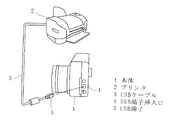
本発明の実施の形態1のデジタルスチルカメラ(以下DSCという。)を以下、図面を参照して説明する。図1は、本発明の実施の形態1のDSCの使用状況を示す斜視図である。DSCの本体1は、本発明の接続部の一例であるUSB端子挿入口4を有し、USB端子挿入口4には、USB端子5が挿入され、本体1とプリンタ2とがUSBケーブル3を介して接続される。USB端子挿入口4には、接続検出部(図示せず)が接続され、USB端子挿入口4にUSB端子5が挿入され、本発明のDSCはプリンタ2が接続されたことを検出することができる。
(Embodiment 1)
A digital still camera (hereinafter referred to as DSC) according to
図2は、実施の形態1のDSCの裏面斜視図を示す。本体1の上部には、記録、再生等の各種の複数のモードを切り替えるための、本発明のモード操作部の一例であるモードダイヤル14が設置されている。また、本体1の裏面には、記録されるべき画像または記録された画像を覗き見るためのEVF15、および上記の画像を外部から見ることができる、本発明の表示装置の一例である液晶モニタ16が装備されている。
FIG. 2 is a rear perspective view of the DSC according to the first embodiment. A
図3は、実施の形態1のDSCの構成を示すブロック図である。制御部13には、接続検出部12、USB端子挿入口4、モードダイヤル14、EVF15、液晶モニタ16が接続されている。接続検出部12は、USB端子挿入口4に接続されているプリンタ2からの電圧を検出することにより、プリンタ2の接続状態またはプリンタ2の接続解除状態を検出する機能を有している。制御部13は、記録モード、再生モード等の各種モードを有し、各モードを切り替える機能、およびプリンタ2が接続されたときプリンタ2へ画像データを送信する機能を有している。
FIG. 3 is a block diagram illustrating a configuration of the DSC according to the first embodiment . Are
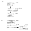
次に、上記の構成の本実施の形態のDSCの動作を図4(a)、(b)に示すフロー図に沿って説明する。USB端子挿入口4にプリンタ2に接続されたUSBケーブル3のUSB端子5が挿入されると、接続検出部12は、プリンタ2から印加される電圧を検出することにより、プリンタ2が接続されている状態を検出する(ステップ101)。そして、接続検出部12からの情報は、制御部13に伝えられ、制御部13は、モードダイヤル14により設定されているモードから、転送モードへと切り替える(ステップ102)。
Next, the operation of the DSC having the above-described configuration according to the present embodiment will be described with reference to the flowcharts shown in FIGS. When the
図5は、制御部13における転送モードへの切換動作を示す図である。モードダイヤル14は、記録モード、再生モード、転送モード等の各種モードを選択できるためのスイッチである。また、端子22は、選択されたモードからの信号を伝達するための端子である。接点17,18,19はb接点スイッチであり、接点20は、a接点スイッチである。また、接点17,18,19は接点20に連動する。今、仮に記録モードが選択されているものとすると、接点17は閉じ、接点20は開いている。そして、記録モードのラインは、接点17およびモードダイヤル14を介して端子22に接続されている。
FIG. 5 is a diagram illustrating the switching operation to the transfer mode in the
制御部13が接続検出部12からの外部機器の接続状態を判断する情報を受け取ると、制御部13は、接点17を開放し、接点20を閉鎖する。このような動作により、制御部13は、モードダイヤル14が記録モードに設定されていても、記録モードのラインを開放し、転送モードのラインを端子22に接続する。
When the
制御部13は、端子22が転送モードラインに接続されていることを確認すると、記録モードから転送モードに移行する。その後、制御部13は、プリンタ2へ画像情報を送信するよう制御を行なう(ステップ103)。
When the
このように、実施の形態1のDSCによれば、モードダイヤル14を記録モードのままで、プリンタ2に接続しても、内部の制御部13でモードを記録モードから転送モードに切り替えることができるので、ユーザーがモードダイヤル14の設定変更を忘れても、プリンタ2に画像を送信することができ、使い勝手のよいDSCを提供することができる。
As described above, according to the DSC of the first embodiment, even when the
なお、以上の説明では、外部機器は、プリンタ2であるとして説明してきたが、外部機器は、パソコンであってもよいし、携帯電話等他の機器であってもよい。
In the above description, the external device has been described as a
また、本発明の接続検出部は、USB端子挿入口4に接続されているプリンタ2等の外部機器からの電圧を検出することにより、外部機器の接続状態を検出する機能を有しているとして説明したが、本発明の接続検出部は、ケーブルが接続されたことにより接点が入り切りされる構成等、上記以外の方法で外部機器が接続されたことが検出される構成であってもよい。
The connection detection unit of the present invention has a function of detecting the connection state of the external device by detecting the voltage from the external device such as the
また上記では、モードダイヤル14が記録モードに設定されていても外部機器が接続されている状態が検出されたときに、自動的に転送モードに切り替わる構成を示したが、モードダイヤル14が他のモードに設定されている場合であっても、外部機器の接続が検出されると、自動的に転送モードに切り替わる。
In the above description, the configuration in which the
また、上記では、本発明の接続検出部から外部機器が接続されたことを検出して、モードダイヤル14において設定されているモードから転送モードに自動的に移行する構成、動作を説明したが、逆に外部機器の接続が解除されたときに、本発明の接続検出部が上記解除を検出する構成、動作も考えられる。
In the above description, the configuration and operation for detecting that the external device is connected from the connection detection unit of the present invention and automatically shifting from the mode set in the
その場合は、図4(b)に示すように、外部機器の接続が解除されたことが接続検出部12により検出された後(ステップ104)、あらかじめモードダイヤル14において設定されていたモードに自動的に戻る(ステップ105)構成であればよい。例えば、モードダイヤル14が記録モードに設定されていた場合(ステップ106)は、図5に示す回路において、接続検出部12が外部機器の接続解除を検出したとき、接点20が開放され、接点17が閉鎖されることにより、転送モードラインの代わりに記録モードラインが端子22に接続される動作となる。従って、外部機器が接続されていることを接続検出部12により検出されている間は、モードダイヤル14をどの設定にしても制御部13は転送モードで動作する一方、外部機器の接続が解除されたことを接続検出部12により検出されたときは、そのときにモードダイヤル14で設定されているモードで制御部13は動作する。すなわち、外部機器が接続されている状態で、モードダイヤル14を変更することができ、ユーザーは、外部機器の接続を外した後に使用されるべきモードをあらかじめ選択しておくことができる。
In this case, as shown in FIG. 4B, after the
また、記録された画像がEVFで表示されていた場合は、外部機器が接続されたときに制御部13は、画像の表示を本発明の表示装置の一例である液晶モニタ16に切り替えてもよい(ステップ102)。その場合は、外部機器に送信される画像の確認をEVFを覗き込むことなく、液晶モニタの画面で確認することができるので、さらに使い勝手のよいDSCを提供することができる。
When the recorded image is displayed in EVF, the
図6は、一般的なDSCのブロック構成を示す。ここで、上記の制御部13は、一例として図5に示す、モードダイヤル14によるモードの切り替えを認識する等の動作を行うUI制御部307、モード設定の処理等DSCの動作全体の制御を行うシステム制御部309等により構成され、接続検出部12が一例としてI/O制御部305等により構成されてもよい。
FIG. 6 shows a block configuration of a general DSC. Here, the
また、以上の説明では、制御部13の一部は図5に示す回路で構成されるとしたが、図5に示す回路以外であっても同様の動作をする回路であってもよく、またハード回路により構成されるのではなくソフトにより構成されてもよいことはいうまでもない。
Further, in the above description, a part of the
また、以上の説明では、USB端子挿入口4にUSB端子5が挿入されると、制御部13は転送モードへと切り替えるよう構成したが、制御部13は、再生モードをさらに有し、USB端子挿入口4にUSB端子5が挿入されると、再生モードへと切り替えるよう構成してもよい。ここで、再生モードとは記録済みの画像データを表示するときの動作モードである。その場合、本発明の転送モードとは、転送モードと再生モードとを1つの動作モードに併合したモードに対応する。または、本発明の転送モードは、転送モードと記録モードとを1つの動作モードに併合したモードであってもよい。
In the above description, when the
(実施の形態2)
図7は、本発明に関連する発明の実施の形態2のDSCの構成を示すブロック図である。本実施の形態において、実施の形態1と同様の構成要素については同じ参照番号を付し、その説明を省略する。
(Embodiment 2)
FIG. 7 is a block diagram showing a configuration of a DSC according to the second embodiment of the invention related to the present invention. In the present embodiment, the same components as those in the first embodiment are denoted by the same reference numerals, and the description thereof is omitted.
USB端子挿入口4には、USB端子挿入口4を介して接続される外部機器を判別することができる外部機器判別部21が接続され、外部機器判別部21には、制御部23が接続されている。そして、制御部23には、液晶モニタ16が接続されている。
The USB
次に上記の構成のDSCの動作を図8を参照しながら説明する。USB端子挿入口4に、USBケーブル3が接続されている状態で、制御部23は外部機器との間でネゴシエーションを開始し(ステップ201)、外部機器判別部21が、プリンタコードを受信しているかどうかを確認する(ステップ202)。外部機器判別部21がプリンタコードを受信していることを判断した場合は、制御部23は、プリンタ2に画像情報を送信するための直接プリントモードに移行し、その旨を液晶モニタ16に表示させる(ステップ203)。このとき、液晶モニタ16には、例えば、プリンタ2からの要求に応えるのに必要な項目が表示される。そして、ユーザは、液晶モニタ16に表示される項目を選択することにより、プリンタ2において本来必要な印刷条件等の設定をDSCの液晶モニタ16を介して行うことができる。
Next, the operation of the DSC having the above configuration will be described with reference to FIG. To the USB
外部機器判別部21は、プリンタコードを受信していないと判断している場合には、パソコンからのATAPIコードを受信していないかどうかを確認する(ステップ204)。外部機器判別部21がパソコンからのATAPIコードを受信していると判断した場合は、制御部23は、パソコンに画像情報を送信するためのマスストレージモードに移行し、その旨を液晶モニタ16に表示させる(ステップ205)。このとき、液晶モニタ16には、例えば、DSCからパソコンを介してプリンタの制御が可能である旨の表示がされる。そして、ユーザは、液晶モニタ16に表示される項目を選択することにより、パソコンにおいて本来必要な印刷条件等の設定をDSCの液晶モニタ16を介して行うことができる。
External
USB端子挿入口4にUSBケーブル3が接続されているにもかかわらず、外部機器判別部21が、プリンタコードもATAPIコードも受信していないと判断した場合は、制御部23は、その他の通信モードに移行し、その旨を液晶モニタ16に表示させる(ステップ206)。その他の通信モードにおいては、例えば製品製造時に内部パラメータを設定したり、製品の修理時に設定されたパラメータの変更を行ったりすることができる。
If the external
以上のように、本実施の形態のDSCによれば、液晶モニタ16において接続されている外部機器が表示されるため使い勝手がよく、ユーザーは、接続されている外部機器を容易に認識することができる。
As described above, according to the DSC of the present embodiment, since the connected external device is displayed on the
なお、本実施の形態における外部機器判別部21は、例えば図6に示す、通信処理部308、I/O制御部305等により構成され、制御部23がシステム制御部309等により実現することができる。
Note that the external
また、本実施の形態の上記の説明では、機器コードは、プリンタコードまたはATAPIコードであるとしたが、外部機器判別部21が判別することができるコードであれば、どのようなコードであってもよい。
In the above description of this embodiment, equipment code is set to a printer code or ATAPI code, if the code which can be external
さらに、外部機器判別部は、機器コードにより接続された外部機器を判別するのではなく、電圧信号、または接点信号など別の信号により、接続された外部機器を認識することができる構成であってもよく、その場合も上記と同様の効果を得ることができる。 Further, the external equipment discriminating unit, instead of determining the external device connected by equipment code, by another signal such as a voltage signal or a contact signal, a configuration that can recognize the connected external device In this case, the same effect as described above can be obtained.
また、以上の説明では、外部機器は、プリンタまたはパソコンであるとして説明してきたが、外部機器は、携帯電話等他の機器であってもよい。その場合も、外部機器判別部が判別することができれば上記と同様の効果がある。 In the above description, the external device has been described as a printer or a personal computer, external device may be a cellular phone or the like other equipment. Also in this case, there is the same effect if it is possible to external equipment discriminating portion discriminates.
(実施の形態3)
図9は、実施の形態3のDSCの構成を示すブロック図である。本実施の形態において、実施の形態1〜2における構成要素と同様の構成要素については、同じ参照番号を付し、その説明を省略する。
(Embodiment 3)
FIG. 9 is a block diagram showing the configuration of the DSC of the third embodiment. In the present embodiment, the same constituent elements as those in the first and second embodiments are denoted by the same reference numerals, and the description thereof is omitted.
実施の形態3のDSCは、USB端子挿入口4に接続された制御部33を備え、制御部33には、液晶モニタ16、RAM32、およびメモリーカード31が接続されている。そして、USB端子挿入口4には、外部機器としてプリンタ2が接続されている。制御部33は、記録された画像のうちの一部または全部を一括してプリンタ2に送信し、プリンタ2から印刷させるためのDPOFモードを有している。このDPOFモードは、モードダイヤル14等により選択することにより設定することができる。DPOFモードが選択されていると、記録された画像のうちの所望の画像のみをまとめてプリンタ2に印刷させることができる。そして選択された画像の情報は、メモリーカード31にDPOFファイルとして格納される。
DSC of the third embodiment is provided with a USB
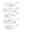
次に以上の構成の本実施の形態のDSCの動作を図10を参照しながら説明する。制御部33において、モードダイヤル14等によりDPOFモードが選択されているとき、DSCからプリンタ2へ送信された画像の印刷が開始されると、プリンタ2は印刷が開始された画像の情報を、DSCの制御部33に送信する。制御部33は、ファイル情報を取得し(ステップ301)、メモリーカード31に格納されているDPOFファイルから該当する情報を検索する(ステップ302)。制御部33は、次にDPOFファイルから検索された画像データをRAM32に展開し(ステップ303)、RAM32上の画像データを表示用のデータに変換する(ステップ304)。その後、制御部33は、変換された画像データを液晶モニタ16に表示させる(ステップ305)。
Next, the operation of the DSC of the present embodiment having the above configuration will be described with reference to FIG. In the
以上のような動作により、ユーザーは、プリンタ2により印刷されている画像を、DSCの液晶モニタ16を介して確認することができる。従って、プリンタ2がDSCから離れた場所にある場合においても容易に印刷中の画像を確認することができる。
Through the operation as described above, the user can check the image printed by the
なお、制御部33は、1つの画像につき、プリント開始情報に加えて、プリント終了情報を取得して、当該画像データに対応する表示用データを液晶モニタ16に表示させてもよい。その場合、制御部33は、プリント終了情報を得た画像が、正常に印刷が終了されたものと判断することができるので、このような情報をRAMに格納することにより、ユーザーは液晶モニタ16から正常に印刷が終了した画像の一覧を確認することもできる。
The
また、制御部33は、プリント終了情報に代えて、正常に印刷ができなかった画像のエラー情報を取得してもよい。これにより、正常に印刷が終了しなかった画像の一覧をユーザーは液晶モニタ16で確認することができる。
Further, the
プリンタ2がDSCの近くに存在する場合であっても、紙詰まり等の印刷エラーが発生し、画像の一部しか印刷されていない場合は、従来は、エラーが発生した画像を特定することが困難であった。しかし、上記のような動作により、どの画像が正常に印刷が終了し、どの画像にエラーが発生したかを、ユーザーはすぐに把握することができる。そして、その場合は、ユーザーは、再びDPOFモードにおいて、印刷ができなかった画像を選択し、当該画像の印刷の指示を出せばよい。
Even when the
また、以上の説明では液晶モニタ16に表示されるのは、画像データから変換された表示用データであるとして説明したが、表示用データとして、画像データのビット数を低減させたものや、何枚中何枚目等の画像データに対応する文字情報が表示されてもよい、また、それらの両方が表示されてもよい。例えば、図11は、印刷中の画像情報に加えて文字情報が表示される場合の液晶モニタの画面の一例を示す。図11(a)は、画像の印刷を1枚ずつ選択する選択画像モードとDPOFモードとの選択を表示する画面例であり、図11(b)は、印刷の開始の確認のための画面例であり、図11(c)は、印刷中の画像とDPOFモードで指定した残りの印刷すべき画像が5枚であることを示す画面例である。 In the above description, it has been described that what is displayed on the liquid crystal monitor 16 is display data converted from the image data. However, as the display data, the number of bits of the image data is reduced. Character information corresponding to image data such as the number of sheets may be displayed, or both of them may be displayed. For example, FIG. 11 shows an example of the screen of the liquid crystal monitor when character information is displayed in addition to the image information being printed. FIG. 11A shows an example of a screen that displays the selection of the selected image mode and DPOF mode for selecting image printing one by one, and FIG. 11B shows an example of a screen for confirming the start of printing. FIG. 11C shows an example of a screen indicating that there are five images to be printed and the remaining images to be printed specified in the DPOF mode.
また、本実施の形態の上記の説明において、記憶部は、メモリーカード31であるとしたが、記憶部は、画像情報、DPOF設定情報を記憶することができれば他の記憶部であってもよい。
Further, in the above description of this embodiment, serial憶部has been that the
また、本実施の形態の上記の説明では、一括印刷モードをDPOFモードとして説明してきたが、記録された画像の全部または一部をバッチ処理で印刷することができるモードであれば他のモードであってもよい。 In the above description of this embodiment, Batch is a print mode has been described as a DPOF mode, recorded other modes as long as all or a mode that can be printed partially in the batch processing of the image It may be.
また、制御部33は、図6に示す構成においては、例えば、画像圧縮処理部302、メモリーカード31への情報の出し入れを制御するメディア制御部306、システム制御部309、通信処理部308、およびI/O制御部305等から構成することができる。
In the configuration shown in FIG. 6, the
(実施の形態4)
図12は、本発明に関連する発明の実施の形態4のDSCの構成を示すブロック図である。本実施の形態において、実施の形態1〜3における構成要素と同様の構成要素については、同じ参照番号を付し、その説明を省略する。
(Embodiment 4)
FIG. 12 is a block diagram showing the configuration of the DSC according to the fourth embodiment of the invention related to the present invention. In the present embodiment, the same constituent elements as those in the first to third embodiments are denoted by the same reference numerals, and the description thereof is omitted.
実施の形態4のDSCは制御部43を有しており、制御部43には、本体1に脱着可能なメモリーカード41が接続されている。本体1の底面は、図13に示すように、本体1の底面側に、挿入されたメモリーカード41を覆うように開閉可能に扉45が設けられている。扉45を開放することにより、メモリーカード41を本体1のメモリーカード挿入口46に挿入することができる構成である。また、本体1には、扉45を閉鎖したときに信号を出力する接点44が設置されており、接点44は、その出力が制御部43に伝達されるように接続されている。
DSC of the fourth embodiment has a
上記の構成の本実施の形態のDSCの動作を図14を参照しながら次に説明する。本体1のメモリーカード挿入口46にメモリーカード41を挿入した後、ユーザーは、扉45を閉じる。扉45が閉じられると、接点44から接点信号が制御部43に送られる。制御部43は、メモリーカード41がメモリーカード挿入口46に正しく挿入され、扉45が閉じられた際の接点信号を検出する(ステップ401)と、挿入されたメモリーカード41のチェックを開始する(ステップ402)。そして、制御部43は、メモリーカード41の、全記憶容量、セクタ長、セクタ数等を確認する(ステップ403)。
Next, the operation of the DSC according to the present embodiment having the above-described configuration will be described with reference to FIG. After inserting the
メモリーカード41をチェックする際に、制御部43はメモリーカード41がDPOFファイルを有しているかどうかを確認する(ステップ406)。DPOFファイルが存在することが検出されると、制御部43は、DPOFモードでの表示処理を行う(ステップ407)。そして、表示処理された画像データを、液晶モニタ16に表示させ(ステップ408)、プリンタ2に画像データを送信する。
When checking the
メモリーカード41にDPOFファイルが存在しない場合は、制御部43は、メモリーカード41のアクセス可能状態を検出し(ステップ404)、接続されているプリンタ2等の外部機器に、メモリーカード41がアクセス可能状態である旨を通知する(ステップ405)。
When the DPOF file does not exist in the
上記のような動作によれば、扉45が閉じられたときのみ、メモリーカード41へのアクセスが開始されるので、扉45を開放したままプリンタ2等の外部機器との通信が開始され、その通信中にカードが抜かれて通信が中断する、というトラブルを未然に防ぐことができる。
According to the operation as described above, access to the
なお、接点は、図12においては、a接点として表示されているが、b接点でもよく、扉45が閉じられたとき、接点信号が出力される構造であれば、どのような接点であってもよく、その場合も上記と同様の効果を得ることができる。
Note that contact point, 12 has been shown as a contact point may be a b-contact, when the
また、上記の説明では、接点は、扉45の開閉により接点信号が出される構造であるとしたが、接点は、他の動作により接点信号が出される構造であってもよい。例えば、本体1の底面に、その底面から突出したボタンが設けられ、本体1を机等の平面上に正置したときに、そのボタンが本体1の重みにより押し込まれ、そのときに接点信号が出力される等の構成が考えられる。また、メモリーカード挿入口46に、メモリーカード41を挿入したときに、メモリーカード41がメモリーカード挿入口46から脱出しないように、ロック機構を設け、そのロック機構に接点が設けられ、メモリーカード41がロックされたときに、接点信号が出力される構成であってもよい。
In the above description, contact point is set to a structure in which a contact signal is issued by the opening and closing of the
また、本実施の形態のDSCは、扉45の閉鎖を、制御部43がメモリーカード41へアクセス開始する条件としたものであり、一旦扉45が閉鎖され、外部機器との通信が開始された後は、扉45が開いても通信が中断されることを意図したものではない。
In the DSC of this embodiment, the closing of the
また、上記の制御部43は、例えば、図6に示す構成において、メディア制御部306、システム制御部309、通信処理部308、およびI/O制御部305等から構成することができる。
Further, for example, the
(実施の形態5)
図15は、本発明に関連する発明の実施の形態5のDSCの構成を示すブロック図である。本実施の形態において、実施の形態1〜4における構成要素と同様の構成要素については、同じ参照番号を付し、その説明を省略する。
(Embodiment 5)
FIG. 15 is a block diagram showing a configuration of a DSC according to the fifth embodiment of the invention related to the present invention . In the present embodiment, the same constituent elements as those in the first to fourth embodiments are denoted by the same reference numerals, and the description thereof is omitted.
本実施の形態のDSCは、制御部53と、制御部53に接続されたメモリーカード41を有する。また制御部53には、プリンタ2が接続されている。なお、実施の形態1〜4までにおける構成要素と同様の構成要素については、同じ参照番号を付し、その説明を省略する。
DSC of this embodiment includes a
次に上記の構成のDSCの動作を図16を参照しながら説明する。メモリーカード41に記録された画像情報がプリンタ2に送信されているときに、ユーザーがメモリーカード41を別のメモリーカード41へ交換すると、制御部53は、まずメモリーカード41の取り外し状態を検出し(ステップ501)、プリンタ2との通信を中断する(ステップ502)。このとき、通信が完了している画像データについては、プリンタ2から印刷されるが、通信が完了していない画像データについては、プリンタ2側で消去される。
Next, the operation of the DSC configured as described above will be described with reference to FIG. When the image information recorded on the
そして、別のメモリーカード41がユーザーにより装着されると、制御部53は、その別のメモリーカード41の装着状態を検出し(ステップ503)、図14のステップ401以降の動作へ移行する。
When another
このような動作により、ユーザーが通信中にメモリーカード41を交換しても、再度USBケーブル3を接続し直すことなく、印刷を再開することができる。
With such an operation, even if the user replaces the
なお、上記別のメモリーカード41にDPOFファイルが存在することが確認された(ステップ406)場合は、DPOFモードにおける表示処理が行われ(ステップ407)、DPOF印刷されるべき画像データとともに、印刷枚数、印刷順序等の印刷に関する情報が液晶モニタ16に表示される。
Note that the
また、外部機器はプリンタ2であるとして説明したが、パソコン、携帯電話等であってもよい。ただし、その場合、制御部53は、DPOFファイルに関する動作(ステップ406以降)については行わない。
Although described as an external device is a
また、上記の説明では、メモリーカード41を装着して通信中に別のメモリーカード41に交換する場合の動作について説明したが、本体1にメモリーカード41が装着されていない状態でプリンタ2との接続を行い、その後、メモリーカード41が本体1のメモリーカード挿入口46に挿入された場合は、制御部53は、メモリーカード41の装着状態を検出後、実施の形態4に示すステップ402の動作に移行する。なお、この場合、メモリーカード41の装着状態の検出後、扉45の閉鎖が確認され(ステップ401)てから通信が開始される動作であってもよい。
In the above description, the operation when the
また、制御部53は、例えば図6に示す、メディア制御部306、システム制御部309、および通信処理部308等により構成することができる。
Further, the
(実施の形態6)
実施の形態6のDSCの構成を図17に示す。本実施の形態において、実施の形態1〜5における構成要素と同様の構成要素については、同じ参照番号を付し、その説明を省略する。
(Embodiment 6)
FIG. 17 shows the configuration of the DSC of the sixth embodiment. In the present embodiment, the same components as those in the first to fifth embodiments are denoted by the same reference numerals, and the description thereof is omitted.
本実施の形態のDSCは、制御部63と、制御部63に接続された液晶モニタ16およびメモリーカード41とを備える。また制御部63には、USB端子挿入口4を介してパソコン62が接続されている。
DSC of this embodiment includes a
次に、本実施の形態のDSCの動作を図18を参照しながら説明する。本体1にUSB端子挿入口4を介してパソコン62が接続されていると、制御部63はATAPIコードを受信する(ステップ601)。このとき、制御部63は、ATAPIメモリカードリムーバブルOKコードを受信しているかどうかを確認する(ステップ608)。そして、上記OKコードが受信されていない場合は、パソコン62から画像データのデータブロックの転送が開始され、制御部63は、画像データが転送中であることを検出する(ステップ602)。一方、上記OKコードが受信されている場合は、制御部63は、液晶モニタ16に画像データの転送が終了したことを表示させる(ステップ610)。
Next, the operation of the DSC of this embodiment will be described with reference to FIG. When the
画像データ転送中が検出されると同時に、制御部63は、所定の作動時間に設定されたタイマーをリセットさせた後(ステップ611)、タイマーの作動を開始させ(ステップ606)る。このタイマーの作動時間としては、1つのデータブロックの転送が終了してから次のデータブロックの転送が開始されるまでの最長の時間以上に設定される。このように設定される時間の一例としては、例えば10秒〜20秒が挙げられる。
At the same time that the image data transfer is detected, the
そして、制御部63は、パソコン62から転送された画像データを、メモリーカード41に書き込み(Write)するように処理し(ステップ603)、タイマーが作動中は、液晶モニタ16上に画像データが転送中である旨の表示を継続させる(ステップ604)。
Then, the
メモリーカード41における書き込み処理が終了し(ステップ605)、かつタイマーの作動時間が終了(ステップ607)すると、制御部63は、液晶モニタ16に画像データの転送が終了した旨を表示させる(ステップ610)。
When the writing process in the
一方、タイマーの作動時間が終了せず次のデータブロックの転送が開始されると、タイマーがリセットされ(ステップ611)、新たにタイマーの作動が開始される(ステップ606)。 On the other hand, when transfer of the next data block is started without ending the timer operation time, the timer is reset (step 611), and the timer operation is newly started (step 606).
以上のような動作により、本実施の形態のDSCによると、画像データの転送中は、画像データ転送中の表示が液晶モニタ16に継続して表示されるので、ユーザは、画像データの転送中に誤って、パソコンとの通信を切断するリスクを排除することができる。 With the operation as described above, according to the DSC of the present embodiment, the display during image data transfer is continuously displayed on the liquid crystal monitor 16 during the transfer of the image data. It is possible to eliminate the risk of accidentally disconnecting communication with a personal computer.
なお、以上の説明では、タイマーの作動終了と、メモリーカード41への書き込み処理の終了とをAND条件として、画像データ転送の終了を検出するとしたが、いずれか一方のみの条件で画像データ転送の終了を検出してもよい。そのような場合でも、画像データの転送中に、パソコン62との通信を切断するリスクを低減させることができる。
In the above description, the end of the image data transfer is detected using the AND operation as the end of the timer operation and the end of the writing process to the
また、以上の説明では、タイマーの作動時間は、1つのデータブロックの転送が終了してから次のデータブロックの転送が開始されるまでの時間であるとしたが、この時間は、FATの書き込みに要する時間であってもよく、その場合も上記と同様の効果を得ることができる。 Further, in the above description, the timer operation time is the time from the end of the transfer of one data block to the start of the transfer of the next data block. In this case, the same effect as described above can be obtained.
また、上記では、パソコン62からDSCに画像データが転送される場合を説明したが、逆にDSCからパソコン62に画像データが転送される場合も考えられる。その場合、ステップ605においては、メモリーカード41からの読み出し処理の終了を検出すればよい。また、タイマー作動時間は、数秒に設定される。
In the above description, the case where image data is transferred from the
また、本実施の形態において、上記以外の方法であっても、画像データの転送が時間的に離散したデータブロック毎に転送され、上記画像データの転送が開始されてから終了するまでの間、連続して液晶モニタ16に、上記画像データが転送中である旨の表示がされるものは、本発明の範疇に含まれる。 Further, in the present embodiment, even in a method other than the above, the transfer of the image data is transferred for each data block that is discrete in time, and from the start to the end of the transfer of the image data, A display in which the image data is being transferred is continuously displayed on the liquid crystal monitor 16 is included in the scope of the present invention.
なお、以上までの実施の形態において、本発明の接続部は、USBケーブル3のためのUSB端子挿入口4であるとして説明したが、他のタイプのケーブルの端子挿入口であってもよい。また、端子挿入口でなくても、ケーブルを接続することができる手段であればどのようなタイプの接続部であってもよい。
In the above embodiments, the connection portion of the present invention has been described as the USB
また、以上までの実施の形態において、本発明の表示装置としては、液晶モニタ16に限られることはなく、ELモニタ等、液晶以外のモニタであってもよい。
In the above-described embodiments, the display device of the present invention is not limited to the
また、以上までの実施の形態において、外部機器がケーブルにより接続されるのではなく、例えば無線で接続される場合も考えられる。その場合は、本発明の接続検出部は、外部機器が接続された信号を受信することにより外部機器の接続状態を検出する構成であればよい。 Further, in the embodiment described so far, rather than external device is connected by a cable, it is conceivable to be connected, for example, wirelessly. In that case, the connection detection part of this invention should just be the structure which detects the connection state of an external apparatus by receiving the signal to which the external apparatus was connected.
また、携帯型記憶部は、メモリーカード41に限らず他タイプの記憶部であってもよい。
Further, portable type storage unit may be another type of storage unit is not limited to the
また、以上までの実施の形態において、本発明に関連する発明にかかるプログラムは、上述した本発明のDSCの、制御部の全部または一部の機能をコンピュータにより実行するためのプログラムであって、コンピュータと協働して動作するプログラムである。 In the above-described embodiments , the program according to the invention related to the present invention is a program for causing a computer to execute all or part of the functions of the control unit of the DSC of the present invention described above. A program that operates in cooperation with a computer.
また、本発明に関連する発明に係る記録媒体は、上述した本発明のDSCの、制御部の全部または一部の機能をコンピュータにより実行するためのプログラムを記録した記録媒体であり、コンピュータにより読み取り可能かつ、読み取られた前記プログラムが前記コンピュータと協働して利用される記録媒体である。 A recording medium according to an invention related to the present invention is a recording medium that records a program for executing the function of all or part of the control unit of the DSC of the present invention described above by a computer. A recording medium in which the read program is used in cooperation with the computer.
又、本発明に関連する発明のプログラムの一利用形態は、コンピュータにより読み取り可能な記録媒体に記録され、コンピュータと協働して動作する態様であっても良い。 Further, one use form of the program of the invention related to the present invention may be an aspect in which the program is recorded on a computer-readable recording medium and operates in cooperation with the computer.
又、本発明に関連する発明のプログラムの一利用形態は、伝送媒体中を伝送し、コンピュータにより読みとられ、コンピュータと協働して動作する態様であっても良い。 Further, one use form of the program of the invention related to the present invention may be an aspect in which the program is transmitted through a transmission medium, read by a computer, and operated in cooperation with the computer.
又、記録媒体としては、ROM等が含まれ、伝送媒体としては、インターネット等の伝送媒体、光・電波・音波等が含まれる。 The recording medium includes a ROM and the like, and the transmission medium includes a transmission medium such as the Internet, light, radio waves, sound waves, and the like.
又、上述した本発明に関連する発明のコンピュータは、CPU等の純然たるハードウェアに限らず、ファームウェアや、OS、更に周辺機器を含むものであっても良い。 The computer of the invention related to the present invention described above is not limited to pure hardware such as a CPU, but may include firmware, an OS, and peripheral devices.
尚、以上説明した様に、本発明に関連する発明の構成は、ソフトウェア的に実現しても良いし、ハードウェア的に実現しても良い。 As described above, the configuration of the invention related to the present invention may be realized by software or hardware.
本発明にかかるデジタルスチルカメラによると、外部機器が接続されたときのデジタルスチルカメラにおける使い勝手を良くすることができ、デジタルスチルカメラ等として有用である。 According to the digital still camera according to the present invention, it is possible to improve the usability of the digital still camera when an external device is connected, it is useful as a digital still camera or the like.
1 本体
2 プリンタ
3 USBケーブル
4 USB端子挿入口
5 USB端子
1
Claims (1)
前記接続部に前記プリンタが接続されたこと、および接続が解除されたことを検出する接続検出部と、
記録されるべき画像または記録された画像を使用者が覗き見ることができる電子ビューファインダと、
記録されるべき画像または記録された画像を外部から見ることができる表示装置と、
複数のモードのうちいずれかを選択的に設定するためのモード操作部と、
前記モード操作部に応じて前記複数のモードのいずれかに移行させ、前記接続検出部によって前記接続されたことが検出されたときには、自動的に前記複数のモードのいずれかのモードから転送モードに移行させ、前記接続検出部によって前記接続が解除されたことが検出されたときには、自動的に前記転送モードから前記複数のモードのうちのいずれかのモードに移行させる制御部とを備え、
前記転送モードは、前記プリンタへの画像データの送信を可能にするモードであり、
前記制御部は、前記転送モードへ移行させるとき、前記電子ビューファインダに表示をしている場合、前記プリンタで印刷中の画像を表示させるため、前記電子ビューファインダから前記表示装置に自動的にその表示を切り替えさせ、
前記モード操作部は、前記転送モードのときに、前記接続検出部によって前記接続が解除されたことが検出されたときに前記制御部が移行させるモードを、前記使用者によってあらかじめ設定できるようになっている、デジタルスチルカメラ。 A connection for connecting the printer ;
A connection detection unit that detects that the printer is connected to the connection unit and that the connection is released;
An electronic viewfinder that allows the user to peek at the image to be recorded or the recorded image;
A display device capable of viewing the image to be recorded or the recorded image from the outside;
A mode operation unit for selectively setting one of a plurality of modes;
The mode is changed to one of the plurality of modes according to the mode operation unit, and when the connection detection unit detects that the connection is established, the mode is automatically changed from one of the plurality of modes to the transfer mode. is shifted, when said connecting by said connection detection section has been released is detected, and a control unit for automatically shift from the forward mode to any mode of the plurality of modes,
The transfer mode is a mode that enables transmission of image data to the printer,
The control unit automatically displays the image being printed by the printer from the electronic viewfinder to the display device when displaying on the electronic viewfinder when shifting to the transfer mode. Switch the display,
The mode operation unit can set in advance by the user a mode to be shifted by the control unit when the connection detection unit detects that the connection is released in the transfer mode. A digital still camera.
Priority Applications (1)
| Application Number | Priority Date | Filing Date | Title |
|---|---|---|---|
| JP2003377275A JP4342913B2 (en) | 2002-11-07 | 2003-11-06 | Digital still camera |
Applications Claiming Priority (2)
| Application Number | Priority Date | Filing Date | Title |
|---|---|---|---|
| JP2002324351 | 2002-11-07 | ||
| JP2003377275A JP4342913B2 (en) | 2002-11-07 | 2003-11-06 | Digital still camera |
Publications (3)
| Publication Number | Publication Date |
|---|---|
| JP2004173263A JP2004173263A (en) | 2004-06-17 |
| JP2004173263A5 JP2004173263A5 (en) | 2006-12-21 |
| JP4342913B2 true JP4342913B2 (en) | 2009-10-14 |
Family
ID=32716039
Family Applications (1)
| Application Number | Title | Priority Date | Filing Date |
|---|---|---|---|
| JP2003377275A Expired - Fee Related JP4342913B2 (en) | 2002-11-07 | 2003-11-06 | Digital still camera |
Country Status (1)
| Country | Link |
|---|---|
| JP (1) | JP4342913B2 (en) |
Families Citing this family (8)
| Publication number | Priority date | Publication date | Assignee | Title |
|---|---|---|---|---|
| US7777779B2 (en) | 2003-09-10 | 2010-08-17 | Olympus Corporation | Photographing apparatus, control method for lens barrel of photographing apparatus, printer, control method for printer, and printing system |
| JP2006197302A (en) * | 2005-01-14 | 2006-07-27 | Matsushita Electric Ind Co Ltd | Image reproducing apparatus |
| JP4614385B2 (en) * | 2005-02-02 | 2011-01-19 | キヤノン株式会社 | Image reproducing apparatus, control method therefor, program, and storage medium |
| JP4241847B2 (en) * | 2007-03-15 | 2009-03-18 | セイコーエプソン株式会社 | Television connection detection device and image display device |
| JP2009064118A (en) * | 2007-09-05 | 2009-03-26 | Nec Access Technica Ltd | Backup device for usb device, backup method for usb device used therefor, and its program |
| JP4841646B2 (en) * | 2009-04-28 | 2011-12-21 | オリンパス株式会社 | Imaging device |
| JP5854827B2 (en) * | 2011-12-27 | 2016-02-09 | キヤノン株式会社 | COMMUNICATION DEVICE, ITS CONTROL METHOD, PROGRAM |
| JP6214421B2 (en) | 2014-02-18 | 2017-10-18 | オリンパス株式会社 | Imaging apparatus and imaging method |
-
2003
- 2003-11-06 JP JP2003377275A patent/JP4342913B2/en not_active Expired - Fee Related
Also Published As
| Publication number | Publication date |
|---|---|
| JP2004173263A (en) | 2004-06-17 |
Similar Documents
| Publication | Publication Date | Title |
|---|---|---|
| JP4135735B2 (en) | Image forming apparatus and data processing program | |
| JP4799364B2 (en) | Image forming apparatus and control method thereof | |
| US20040141083A1 (en) | Digital still camera, and control method and program of the same | |
| KR100619150B1 (en) | Image transmission/reception system, image transmission apparatus and image reception apparatus | |
| JP4342913B2 (en) | Digital still camera | |
| US20120176512A1 (en) | Image storage apparatus, image storage method, and control program executed in image storage apparatus | |
| JP3919716B2 (en) | Recording apparatus, image supply system, and control method therefor | |
| JP4532759B2 (en) | Imaging device | |
| JP3927874B2 (en) | Image processing apparatus, control method therefor, program, and storage medium | |
| JP4178025B2 (en) | Print order system | |
| JP2000358207A (en) | Image information processor, its control method and storage medium | |
| JP4878456B2 (en) | Recording medium and imaging apparatus | |
| JP4406709B2 (en) | USB peripheral device and method for selecting device class | |
| JP4480137B2 (en) | Imaging apparatus, computer program, and computer-readable recording medium | |
| JP4067418B2 (en) | Digital camera | |
| JP2005286731A (en) | Imaging device | |
| JP2006319497A (en) | Image pickup device and recording method | |
| JP4366379B2 (en) | Image supply apparatus and control method thereof | |
| JP3652360B2 (en) | Electronic camera | |
| JP2005277958A (en) | Image recording system, imaging apparatus and recording apparatus | |
| JP2001333387A (en) | Equipment, system and method for information communication | |
| JP4058280B2 (en) | Digital imaging device and communication device | |
| JP2004172840A (en) | Information recording system and information recording service system | |
| JP2008028557A (en) | Image processor | |
| JP2005323246A (en) | Image recorder |
Legal Events
| Date | Code | Title | Description |
|---|---|---|---|
| A521 | Request for written amendment filed |
Free format text: JAPANESE INTERMEDIATE CODE: A523 Effective date: 20061102 |
|
| A621 | Written request for application examination |
Free format text: JAPANESE INTERMEDIATE CODE: A621 Effective date: 20061102 |
|
| A131 | Notification of reasons for refusal |
Free format text: JAPANESE INTERMEDIATE CODE: A131 Effective date: 20081216 |
|
| A521 | Request for written amendment filed |
Free format text: JAPANESE INTERMEDIATE CODE: A523 Effective date: 20090212 |
|
| RD02 | Notification of acceptance of power of attorney |
Free format text: JAPANESE INTERMEDIATE CODE: A7422 Effective date: 20090212 |
|
| TRDD | Decision of grant or rejection written | ||
| A01 | Written decision to grant a patent or to grant a registration (utility model) |
Free format text: JAPANESE INTERMEDIATE CODE: A01 Effective date: 20090616 |
|
| A01 | Written decision to grant a patent or to grant a registration (utility model) |
Free format text: JAPANESE INTERMEDIATE CODE: A01 |
|
| A61 | First payment of annual fees (during grant procedure) |
Free format text: JAPANESE INTERMEDIATE CODE: A61 Effective date: 20090708 |
|
| FPAY | Renewal fee payment (event date is renewal date of database) |
Free format text: PAYMENT UNTIL: 20120717 Year of fee payment: 3 |
|
| R150 | Certificate of patent or registration of utility model |
Ref document number: 4342913 Country of ref document: JP Free format text: JAPANESE INTERMEDIATE CODE: R150 Free format text: JAPANESE INTERMEDIATE CODE: R150 |
|
| FPAY | Renewal fee payment (event date is renewal date of database) |
Free format text: PAYMENT UNTIL: 20130717 Year of fee payment: 4 |
|
| FPAY | Renewal fee payment (event date is renewal date of database) |
Free format text: PAYMENT UNTIL: 20130717 Year of fee payment: 4 |
|
| FPAY | Renewal fee payment (event date is renewal date of database) |
Free format text: PAYMENT UNTIL: 20140717 Year of fee payment: 5 |
|
| LAPS | Cancellation because of no payment of annual fees |