JP4341787B2 - Work machine mounting structure - Google Patents
Work machine mounting structure Download PDFInfo
- Publication number
- JP4341787B2 JP4341787B2 JP05104999A JP5104999A JP4341787B2 JP 4341787 B2 JP4341787 B2 JP 4341787B2 JP 05104999 A JP05104999 A JP 05104999A JP 5104999 A JP5104999 A JP 5104999A JP 4341787 B2 JP4341787 B2 JP 4341787B2
- Authority
- JP
- Japan
- Prior art keywords
- hitch
- work machine
- boss
- connecting pin
- work
- Prior art date
- Legal status (The legal status is an assumption and is not a legal conclusion. Google has not performed a legal analysis and makes no representation as to the accuracy of the status listed.)
- Expired - Lifetime
Links
Images


Description
【0001】
【発明の属する技術分野】
本発明は、作業機装着構造に関する。
【0002】
【従来の技術】
従来、本機としてのトラクタに本機側ヒッチを設ける一方、作業機としてのフロントローダに作業機側ヒッチを設けて、同フロントローダをトラクタに両ヒッチを介して着脱自在に装着したものがある。
【0003】
そして、本機側ヒッチには、下方に凹状のフックを設けると共に、同フックよりも上方に位置させて連結ピン挿通孔を形成する一方、作業機側ヒッチには、上記フックに係合する係合ピンを設けると共に、同係合ピンよりも上方に位置させて上記連結ピン挿通孔と符合する連結ピン孔を形成している。
【0004】
このようにして、トラクタにフロントローダを装着する際には、まず、本機側ヒッチのフックに係合ピンを係合させ、同係合ピンを中心に作業機側ヒッチを本機側ヒッチの方へ回動させて、同作業機側ヒッチの連結ピン孔を本機側ピッチの連結ピン挿通孔に符合させ、その後に、両孔中に連結ピンを挿通するようにしている。
【0005】
【発明が解決しようとする課題】
ところが、上記した作業機装着構造では、本機側ヒッチのフックに係合ピンを係合させる作業、さらに、係合ピンを中心に作業機側ヒッチを本機側ヒッチの方へ回動させて、連結ピン孔を連結ピン挿通孔に符合させる作業が煩雑で、作業機装着作業に手間と熟練とを要している。
【0006】
【課題を解決するための手段】
そこで、本発明では、本機に本機側ヒッチを設ける一方、作業機に作業機側ヒッチを設けて、同作業機側ヒッチを本機側ヒッチに着脱自在に装着可能とした作業機装着構造において、作業機は、地上に自立可能となすと共に、同作業機に設けた作業機側ヒッチを連結姿勢に変更可能となして、連結姿勢にある作業機側ヒッチのボス部又は位置決め用係合片は、本機側ヒッチの位置決め用係合片又はボス部と前後方向に対向して位置すべく構成した作業機装着構造であって、本機側ヒッチと作業機側ヒッチのいずれか一方のヒッチは、左右一対のヒッチ形成片に、それぞれ連結ピン挿通用のボス孔を有するボス部を左右方向に軸線を向け、かつ、同一軸線上に対向させて内方へ突出状に設ける一方、他方のヒッチは、板状に形成したヒッチ本体の左右側面に、それぞれ凹状の位置決め用係合片を設けると共に、同ヒッチ本体には連結ピン孔を左右方向に貫通状に形成して、上記左右一対のボス部間に、ヒッチ本体に形成した連結ピン孔の部分を挿入させると共に、各ボス部の外周面に、ヒッチ本体に設けた位置決め用係合片を係合させると、各ボス部のボス孔と連結ピン孔とが符合するようにして、両孔中に連結ピンを抜き差し自在に挿通することにより、両ヒッチを連結可能となし、しかも、上記ボス部と位置決め用係合片及び連結ピン孔の組は、上下方向に間隔を開けて複数設けたことを特徴とする作業機装着構造を提供するものである。
【0008】
【発明の実施の形態】
以下に、本発明の実施の形態について説明する。
【0009】
すなわち、本発明に係る作業機装置構造は、基本的構造として、本機に本機側ヒッチを設ける一方、作業機に作業機側ヒッチを設けて、同作業機側ヒッチを本機側ヒッチに着脱自在に装着可能としている。
【0010】
そして、かかる作業機装着構造は、特徴的構造として、本機側ヒッチと作業機側ヒッチのいずれか一方のヒッチに、連結ピン挿通用のボス孔を有するボス部を左右方向に軸線を向けて設ける一方、他方のヒッチに、上記ボス部の外周面に係合すべく後方へ凹状に形成した位置決め用係合片と、同位置決め用係合片に係合したボス部のボス孔と符合する連結ピン孔とを設け、符合した両孔中に連結ピンを挿通して両ヒッチを連結可能となし、しかも、上記ボス部と位置決め用係合片及び連結ピン孔の組は、上下方向に間隔を開けて複数設けている。
【0011】
このようにして、作業機側ヒッチに本機側ヒッチを接近させることにより、いずれか一方のヒッチに設けたボス部と、他方のヒッチに設けた位置決め用係合片とを簡単かつ確実に係合させることができ、続いて、かかる状態にて符合しているボス孔と連結ピン孔とに連結ピンを挿通することにより、両ヒッチを楽に連結することができる。
【0012】
しかも、作業機は、地上に自立可能となすと共に、同作業機に設けた作業機側ヒッチを連結姿勢に変更可能となして、連結姿勢にある作業機側ヒッチのボス部又は位置決め用係合片は、本機側ヒッチの位置決め用係合片又はボス部と前後方向に対向して位置すべく構成している。
【0013】
このようにして、地上に作業機を自立させると共に、作業機側ヒッチを連結姿勢となしておき、同状態にて、本機を走行移動させて、静置している作業機側ヒッチに本機側ヒッチを近接させるだけで、ボス部と位置決め用係合片との係合が楽に行えると共に、ボス孔と連結ピン孔との符合が確実に行えて、それに続く連結ピンの挿通がスムーズに行える。
【0014】
また、反対の作業手順を遡ることにより、両ヒッチの連結解除が楽に行える。
【0015】
従って、作業機の装着・離脱作業を、熟練を要することなく、楽に行うことができる。
【0016】
【実施例】
以下に、本発明の実施例を図面を参照しながら説明する。
【0017】
図1に示すAは、本発明に係る作業機としてのフロントローダであり、同フロントローダAは、本機としてのトラクタBに着脱自在に装着している。
【0018】
まず、トラクタBについて説明すると、トラクタBは、図1に示すように、機体フレーム1の前部に原動機部2を設け、後部に運転部3を設けて、機体フレーム1の下方の前後側にそれぞれ左右側前・後車輪4,4,5,5を取付けている。
【0019】
そして、機体フレーム1の中途部には、左右一対のヒッチステー6,6を取付け、各ヒッチステー6,6よりそれぞれ板状に形成した本機側ヒッチ7,7を上方へ立上げ状に取付け、両本機側ヒッチ7,7の上端部間には正面視門型の連結フレーム8を跨架している。
【0020】
また、本機側ヒッチ7は、図1〜図3に示すように、ヒッチ本体7aの左右側面の前側中途部に、それぞれ後方へ凹状の位置決め用係合片7b,7b を設けると共に、ヒッチ本体7aの左右側面の後上部にも、それぞれ後方へ凹状の位置決め用係合片7c,7c を設け、各位置決め用係合片7b,7b,7c,7c の直前方に位置するヒッチ本体7aの部分には、それぞれ連結ピン孔7d,7e を左右方向に貫通状に形成している。
【0021】
次に、本発明に係るフロントローダAについて、図1及び図2を参照しながら説明する。
【0022】
すなわち、フロントローダAは、左右一対の作業機側ヒッチ10,10 と、各作業機側ヒッチ10,10 に基端部を枢支した左右一対のリフトアーム11,11 と、両リフトアーム11,11 の先端間に横架したアタッチメントヒッチ12と、同アタッチメントヒッチ12に着脱自在に取付けたアタッチメントとしてのバケット13と、上記リフトアーム11,11 を上下回動作動すべく、各リフトアーム11,11 の中途部と作業機側ヒッチ10,10 との間に介設したリフトアームシリンダ14,14 と、上記バケット13を回動作動すべく、同バケット13の左右側部とリフトアーム11,11 の中途部との間に介設したバケットシリンダ15,15 と、上記リフトアーム11,11 の先端部に取付けたスタンド16とを具備している。11a,11b,12e,14a,14b,15a,15b,18a,19a,19b は、それぞれ枢支・連結部である。17はバケットリンク、18はシリンダ・ロッド支持体、19は連動ロッドである。
【0023】
ここで、スタンド16は、図1に示すように、リフトアーム11に基端部を枢支ピン25により枢支して、リフトアーム11に沿わせた収納姿勢と、下方へ回動させて先端部を接地させた使用姿勢とに姿勢変更可能としており、同スタンド16には、リフトアーム11に基端を枢支した支持アーム26の先端部を、スタンド連結ピン27を介して収納姿勢と使用姿勢のいずれかの姿勢にて連結して、各姿勢を保持できるようにしている。
【0024】
そして、支持アーム26は、ターンバックル式に伸縮長さ調節自在に構成している。
【0025】
作業機側ヒッチ10は、図2及び図3に示すように、左右一対のヒッチ形成片10a,10a の下部に、それぞれ連結ピン挿通用のボス孔10b,10b を有するボス部10c,10c を左右方向に軸線を向け、かつ、同一軸線上に対向させて設け、同様に、両ヒッチ形成片10a,10a の後側中途部にも、ボス孔10d,10d を有するボス部10e,10e を設けている。
【0026】
しかも、左右一対のボス部10c,10c,10e,10e 間には、本機側ヒッチ7のヒッチ本体7aを挿入可能な間隔を保持させて、各ボス部10c,10c,10e,10e をヒッチ形成片10a,10a の内方へ突出状となして、各ボス部10c,10c,10e,10e の外周面が、ヒッチ本体7aに設けた位置決め用係合片7b,7b,7c,7c に係合すべく構成している。
【0027】
さらに、各係合片7b,7b,7c,7c にボス部10c,10c,10e,10e が係合する状態にて、各ボス部10c,10c,10e,10e のボス孔10b,10b,10d,10d と符合する連結ピン孔7d,7e 中に連結ピン20,21 をそれぞれ抜差し自在に挿通している。
【0028】
ここで、フロントローダAは、バケット13を接地させると共に、左右一対のスタンド16,16 を使用姿勢となすことにより、地面G上に自立させることができ、同フロントローダAに設けたリフトアームシリンダ14,14 を伸縮作動させることにより作業機側ヒッチ10,10 の姿勢を枢支・連結部11a を中心に変更可能となしており、作業機側ヒッチ10,10 は、リフトアームシリンダ14,14 を所定の長さに伸縮調節した状態を連結姿勢として設定している。
【0029】
すなわち、作業機側ヒッチ10の連結姿勢は、図2に示すように、作業機側ヒッチ10に設けたボス部10c,10c,10e,10e が、本機側ヒッチ7に設けた位置決め用係合片7b,7b,7c,7c と前後方向に対向して位置し、トラクタBをフロントローダA側に走行移動させれば、各ボス部10c,10c,10e,10e に位置決め用係合片7b,7b,7c,7c がそのまま係合する位置関係となる姿勢である。
【0030】
そして、作業機側ヒッチ10には、リフトアームシリンダ14に近接させて目印用突片22を突設して、同目印用突片22の先端とリフトアームシリンダ14のシリンダ本体14c の先端部とが同一平面上に位置する状態(リフトアームシリンダ14の所定の長さ)で、作業機側ヒッチ10が連結姿勢を採るように設定している。
【0031】
従って、フロントローダAの装着作業を行う際には、同フロントローダAの地面G上に自立させて、リフトアームシリンダ14を目印用突片22を視認しながら所定の長さに伸縮調節する。
【0032】
この際、作業機側ヒッチ10の地上高の調節は、ターンバックル式の支持アーム26を伸縮調節して、スタンド16の使用姿勢を微調節することにより行うことができる。
【0033】
続いて、トラクタBをフロントローダA側に前進走行させて、静置しているフロントローダAの作業機側ヒッチ10に、本機側ヒッチ7を近接させることにより、作業機側ヒッチ10のボス部10c,10c,10e,10e に、本機側ヒッチ7の位置決め用係合片7b,7b,7c,7c を円滑かつ確実に係合させることができる。
【0034】
かかる係合状態では、ボス孔10b,10b,10d,10d に連結ピン孔7d,7e が左右方向にて符合していることより、符合する両孔10b,10b,10d,10d,7d,7e 中に連結ピン20,21 をそれぞれ挿通することにより、両ヒッチ10, 7を連結することができて、楽にフロントローダAの装着作業を終えることができる。
【0035】
また、上記装着作業手順とは反対の手順を遡ることにより、フロントローダAの離脱作業を楽に行うことができる。
【0036】
なお、本実施例では、本機側ヒッチ7に位置決め用係合片7b,7b,7c,7c を設ける一方、作業機側ヒッチ10にボス部10c,10c,10e,10e を設けているが、反対に、本機側ヒッチ7にボス部10c,10c,10e,10e を設ける一方、作業機側ヒッチ10に位置決め用係合片7b,7b,7c,7c を設けることも、また、本機側ヒッチ7に位置決め用係合片7b,7b とボス部10e,10e を設ける一方、作業機側ヒッチ10にボス部10c,10c と位置決め用係合片7c,7c を設けることも、また、本機側ヒッチ7にボス部10c,10c と位置決め用係合片7c,7c を設ける一方、作業機側ヒッチ10に位置決め用係合片7b,7b とボス部10e,10e を設けることもでき、この場合も、上記と同様の効果が得られる。
【0037】
図4は、複動式のリフトアームシリンダ14とバケットシリンダ15をそれぞれ伸縮作動させるための油圧回路図であり、各シリンダ14,15 は、トラクタBに設けた油圧ポンプPと油圧タンクTとに、それぞれリフトアーム用油圧回路30とバケット用油圧回路31とを介して接続しており、各油圧回路30,31 の中途部には、それぞれリフトアーム用切替バルブ32とバケット用切替バルブ33を設けている。
【0038】
ここで、バケット用切替バルブ33には、中立位置(油圧ロック位置)においてバケット用油圧回路31の中途部に逆止弁34を設けて、一方向流れの短路循環流路35を形成している。
【0039】
次に、図5及び図6を参照しながら、アタッチメントヒッチ12へのバケット13の連結構造について説明する。
【0040】
まず、アタッチメントヒッチ12は、リフトアーム11の先端部とバケットリンク17との間に、上下方向に伸延するヒッチ本体12a を架設状に介設し、同ヒッチ本体12a の上端部に係止ピン12b を外側方へ向けて突設する一方、ヒッチ本体12a の下端部にピン孔12c を左右方向に貫通させて形成している。
【0041】
そして、ピン孔12c の前方に位置するヒッチ本体12a の下部前端面には当接部12d を形成している。
【0042】
また、バケット13は、背面左右側部にそれぞれ上下方向に伸延する連結体40,40 を後方へ向けて突設しており、各連結体40,40 の上端部に後下方開放のフック40a,40a を形成する一方、各連結体40,40 の下端部にピン挿通孔40b,40b を形成している。
【0043】
そして、ピン挿通孔40b の前方に位置する連結体40の下端部には当接受部40c を形成しており、同当接受部40c とヒッチ本体12a の当接部12d とが当接した状態にて、ピン挿通孔40b とピン孔12c とが左右方向に符合するようにしている。
【0044】
ここで、リフトアーム11の先端部には左右一対の連結ピン収納片41,41 を突設し、同連結ピン収納片41,41 に左右方向に貫通する連結ピン収納孔42,42 を形成して、両連結ピン収納孔42,42 中に、ヒッチ本体12a と連結体40とを連結する連結ピン43を左右方向に抜差し自在に挿通して架設状に収納することができるようにしている。
【0045】
そして、図6に示すように、バケットシリンダ15を伸長させることにより、ヒッチ本体12a を枢支・連結部11b を中心に反時計廻り回動させると、ヒッチ本体12a の下端が収納状態にある連結ピン43に当接して、同ヒッチ本体12a の回動が規制され、同ヒッチ本体12a は、リフトアーム11に対して略一定のアタッチメント連結姿勢に保持されるようにしている。
【0046】
また、連結体40の後端縁部には、円弧面40d を形成しており、同円弧面40d は、リフトアーム11の枢支・連結部11a を中心として、同リフトアーム11が上下回動作動した際に、上記のように略一定のアタッチメント連結姿勢に保持された係止ピン12b が描く円弧軌跡に沿うように形成している。
【0047】
上記のような構成により、アタッチメントヒッチ12にバケット13を連結する作業は、次の手順にしたがって行う。
【0048】
▲1▼図5に示すように、まず、ヒッチ本体12a の下端を、連結ピン収納片41,41 に収納した連結ピン43に当接させて、同ヒッチ本体12a を略一定のアタッチメント連結姿勢に保持させる。
【0049】
▲2▼かかる状態にて、ヒッチ本体12a の上端部に突設した係止ピン12b を連結体40の円弧面40d の下部に当接させ、同状態よりリフトアーム11を上方へ回動させる。
【0050】
▲3▼図6に示すように、係止ピン12b を円弧面40d に沿わせて摺動させながらフック40a に係止させる。
【0051】
▲4▼かかる状態より、バケットシリンダ15を短縮作動させて、ヒッチ本体12a を枢支・連結部11b を中心に図6に示す時計廻りに回動させると、バケット13が係止ピン12b を中心に反時計廻りに回動して、ヒッチ本体12a の当接部12d に連結体40の当接受部40c が当接して、ピン挿通孔40b とピン孔12c とが符合する。
【0052】
▲5▼連結ピン収納片41,41 の連結ピン収納孔42,42 中に挿通して架設状に収納している連結ピン43を引抜いて、同連結ピン43を符合している上記ピン挿通孔40b とピン孔12c 中に挿通して、アタッチメントヒッチ12にバケット13を円滑かつ確実に連結することができる。
【0053】
また、上記した連結作業手順と反対の手順を遡ることにより、バケット13の離脱作業も円滑かつ確実に行うことができる。
【0054】
【発明の効果】
本発明では、本機に本機側ヒッチを設ける一方、作業機に作業機側ヒッチを設けて、同作業機側ヒッチを本機側ヒッチに着脱自在に装着可能とした作業機装着構造において、作業機は、地上に自立可能となすと共に、同作業機に設けた作業機側ヒッチを連結姿勢に変更可能となして、連結姿勢にある作業機側ヒッチのボス部又は位置決め用係合片は、本機側ヒッチの位置決め用係合片又はボス部と前後方向に対向して位置すべく構成した作業機装着構造であって、本機側ヒッチと作業機側ヒッチのいずれか一方のヒッチは、左右一対のヒッチ形成片に、それぞれ連結ピン挿通用のボス孔を有するボス部を左右方向に軸線を向け、かつ、同一軸線上に対向させて内方へ突出状に設ける一方、他方のヒッチは、板状に形成したヒッチ本体の左右側面に、それぞれ凹状の位置決め用係合片を設けると共に、同ヒッチ本体には連結ピン孔を左右方向に貫通状に形成して、上記左右一対のボス部間に、ヒッチ本体に形成した連結ピン孔の部分を挿入させると共に、各ボス部の外周面に、ヒッチ本体に設けた位置決め用係合片を係合させると、各ボス部のボス孔と連結ピン孔とが符合するようにして、両孔中に連結ピンを抜き差し自在に挿通することにより、両ヒッチを連結可能となし、しかも、上記ボス部と位置決め用係合片及び連結ピン孔の組は、上下方向に間隔を開けて複数設けている。
【0058】
このようにして、地上に作業機を自立させると共に、作業機側ヒッチを連結姿勢となしておき、同状態にて、本機を走行移動させて、静置している作業機側ヒッチに本機側ヒッチを近接させるだけで、ボス部と位置決め用係合片との係合が楽に行えると共に、ボス孔と連結ピン孔との符合が確実に行えて、それに続く連結ピンの挿通がスムーズに行える。
【0059】
また、反対の作業手順を遡ることにより、両ヒッチの連結解除が楽に行える。
【0060】
従って、作業機の装着・離脱作業を、熟練を要することなく、楽に行うことができる。
【図面の簡単な説明】
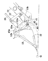
【図1】本発明に係る作業機装着構造を具備するフロントローダの側面図。
【図2】同要部の側面説明図。
【図3】同要部の平面説明図。
【図4】油圧回路図。
【図5】バケットの連結作業説明図。
【図6】バケットの連結作業説明図。
【符号の説明】
A フロントローダ
B トラクタ
1 機体フレーム
2 原動機部
3 運転部
4 前車輪
5 後車輪[0001]
BACKGROUND OF THE INVENTION
The present invention relates to a work machine mounting structure.
[0002]
[Prior art]
Conventionally, a tractor as a machine has a hitch on the machine side, while a front loader as a work machine is provided with a work machine side hitch, and the front loader is detachably attached to the tractor via both hitches. .
[0003]
The machine-side hitch is provided with a concave hook on the lower side and is positioned above the hook to form a connecting pin insertion hole, while the work machine-side hitch is engaged with the hook. A coupling pin is provided, and a coupling pin hole is formed that is positioned above the engagement pin and coincides with the coupling pin insertion hole.
[0004]
Thus, when the front loader is mounted on the tractor, first, the engagement pin is engaged with the hook of the machine side hitch, and the work machine side hitch is centered on the engagement pin. The connecting pin hole of the work machine side hitch is aligned with the connecting pin insertion hole of the machine side pitch, and then the connecting pin is inserted into both holes.
[0005]
[Problems to be solved by the invention]
However, in the work machine mounting structure described above, the work pin is engaged with the hook of the machine side hitch, and further, the work machine side hitch is rotated toward the machine side hitch around the engagement pin. The operation of aligning the connection pin hole with the connection pin insertion hole is complicated, and labor and skill are required for the work machine mounting operation.
[0006]
[Means for Solving the Problems]
Therefore, in the present invention, a work machine mounting structure in which the work machine side hitch is provided in the work machine, the work machine side hitch is provided in the work machine, and the work machine side hitch can be detachably attached to the work machine side hitch. The work machine can stand on the ground, and the work machine side hitch provided on the work machine can be changed to the connected posture so that the boss part of the work machine side hitch in the connected posture or the positioning engagement The piece is a work machine mounting structure configured to be positioned in the front-rear direction opposite to the positioning engagement piece or the boss portion of the machine side hitch, and either the machine side hitch or the work machine side hitch The hitch is provided in a pair of left and right hitch forming pieces, each having a boss portion having a boss hole for insertion of a connecting pin directed in the left-right direction and facing the same axis so as to protrude inward, while the other The hitch body is a plate-shaped hitch body A concave positioning engagement piece is provided on each of the left and right side surfaces, and a connecting pin hole is formed in the hitch body in a penetrating manner in the left and right direction, and the connection formed on the hitch body between the pair of left and right bosses. When the pin hole part is inserted and the positioning engagement piece provided on the hitch body is engaged with the outer peripheral surface of each boss part, the boss hole of each boss part and the connecting pin hole are aligned. Both hitches can be connected by inserting the connecting pins into the holes so that they can be inserted and removed , and the set of the boss, the positioning engagement piece and the connecting pin hole is spaced apart in the vertical direction. It is an object of the present invention to provide a work machine mounting structure characterized in that a plurality of work machines are provided.
[0008]
DETAILED DESCRIPTION OF THE INVENTION
Embodiments of the present invention will be described below.
[0009]
In other words, the work machine device structure according to the present invention has a basic machine structure in which the machine side hitch is provided in the machine, while the work machine side hitch is provided in the work machine, and the work machine side hitch is used as the machine side hitch. It can be attached detachably.
[0010]
Such a work machine mounting structure has a characteristic structure in which a boss portion having a boss hole for inserting a connecting pin is directed in the left-right direction on either the main machine side hitch or the work machine side hitch. On the other hand, the other hitch is aligned with the positioning engagement piece formed in a concave shape in the rear to be engaged with the outer peripheral surface of the boss portion, and the boss hole of the boss portion engaged with the positioning engagement piece. A connecting pin hole is provided, and the hitch can be connected by inserting the connecting pin into the matching holes, and the set of the boss portion, the positioning engagement piece and the connecting pin hole is spaced vertically. There are multiple open.
[0011]
In this way, by approaching the work machine side hitch to the work machine side hitch, the boss provided on one of the hitches and the positioning engagement piece provided on the other hitch are easily and reliably engaged. Subsequently, the hitch can be easily connected by inserting the connecting pin through the boss hole and the connecting pin hole which match in this state.
[0012]
In addition, the work machine can stand on the ground, and the work machine side hitch provided on the work machine can be changed to the connected posture, so that the boss portion of the work machine side hitch in the connected posture or the positioning engagement The piece is configured to be positioned opposite to the positioning engagement piece or the boss portion of the machine-side hitch in the front-rear direction.
[0013]
In this way, the work implement is made to stand on the ground, and the work implement side hitch is set to the connected posture, and in this state, the machine is moved and moved to the stationary work implement side hitch. By simply bringing the machine-side hitch close, the boss part can be easily engaged with the positioning engagement piece, and the boss hole and the connecting pin hole can be reliably aligned, and the subsequent connecting pin can be smoothly inserted. Yes.
[0014]
In addition, it is possible to easily disconnect both hitches by going back to the opposite work procedure.
[0015]
Accordingly, the work machine can be easily attached and detached without requiring skill.
[0016]
【Example】
Embodiments of the present invention will be described below with reference to the drawings.
[0017]
A shown in FIG. 1 is a front loader as a working machine according to the present invention, and the front loader A is detachably attached to a tractor B as a main machine.
[0018]
First, the tractor B will be described. As shown in FIG. 1, the tractor B is provided with a
[0019]
A pair of left and right hitch stays 6 and 6 are attached to the middle part of the body frame 1, and the machine-
[0020]
Further, as shown in FIGS. 1 to 3, the machine-
[0021]
Next, the front loader A according to the present invention will be described with reference to FIGS.
[0022]
That is, the front loader A includes a pair of left and right work implement
[0023]
Here, as shown in FIG. 1, the stand 16 is pivotally supported by a
[0024]
The
[0025]
As shown in FIGS. 2 and 3, the work
[0026]
In addition, the
[0027]
Further, in a state where the
[0028]
Here, the front loader A can be made to stand on the ground G by grounding the
[0029]
That is, the connecting posture of the work implement
[0030]
The work implement
[0031]
Therefore, when the mounting operation of the front loader A is performed, the
[0032]
At this time, the ground clearance of the work implement
[0033]
Subsequently, the tractor B is moved forward to the front loader A side, and the
[0034]
In this engaged state, the connecting
[0035]
Further, the work of detaching the front loader A can be easily performed by going back to the procedure opposite to the mounting procedure.
[0036]
In the present embodiment,
[0037]
FIG. 4 is a hydraulic circuit diagram for extending and retracting the double-acting
[0038]
Here, the switching
[0039]
Next, the connection structure of the
[0040]
First, the
[0041]
A
[0042]
In addition, the
[0043]
A
[0044]
Here, a pair of left and right connecting
[0045]
Then, as shown in FIG. 6, when the
[0046]
A
[0047]
With the above configuration, the operation of connecting the
[0048]
(1) As shown in FIG. 5, first, the lower end of the hitch
[0049]
(2) In this state, the locking
[0050]
(3) As shown in FIG. 6, the locking
[0051]
(4) From this state, when the
[0052]
(5) The above-described pin insertion hole which is inserted into the connection pin storage holes 42 and 42 of the connection
[0053]
Moreover, the
[0054]
【The invention's effect】
In the present invention, in the work machine mounting structure in which the machine side hitch is provided in the machine, the work machine side hitch is provided in the work machine, and the work machine side hitch can be detachably attached to the machine side hitch. The work implement can stand on the ground, and the work implement side hitch provided on the work implement can be changed to the connected posture, and the boss portion or positioning engagement piece of the work implement side hitch in the connected posture is The working machine mounting structure configured to be positioned opposite to the positioning engagement piece or boss portion of the machine side hitch in the front-rear direction, and either the machine side hitch or the work machine side hitch is The pair of left and right hitch-forming pieces are provided with boss portions each having a boss hole for inserting a connecting pin so that the axis is directed in the left-right direction and facing the same axis so as to protrude inward, while the other hitch Is the left and right sides of the hitch body In addition, each of the hitch body has a connecting pin hole formed in the hitch body between the pair of left and right bosses. When the positioning engagement piece provided on the hitch body is engaged with the outer peripheral surface of each boss portion, the boss hole of each boss portion and the connecting pin hole are aligned with each other. Both hitches can be connected by removably inserting the connecting pin into the hole, and a plurality of sets of the boss part, positioning engagement piece and connecting pin hole are provided at intervals in the vertical direction. ing.
[0058]
In this way, the work implement is made to stand on the ground, and the work implement side hitch is set to the connected posture. By simply bringing the machine-side hitch close, the boss part can be easily engaged with the positioning engagement piece, and the boss hole and the connecting pin hole can be reliably aligned, and the subsequent connecting pin can be smoothly inserted. Yes.
[0059]
In addition, it is possible to easily disconnect both hitches by going back to the opposite work procedure.
[0060]
Accordingly, the work machine can be easily attached and detached without requiring skill.
[Brief description of the drawings]
FIG. 1 is a side view of a front loader provided with a work machine mounting structure according to the present invention.
FIG. 2 is an explanatory side view of the main part.
FIG. 3 is an explanatory plan view of the main part.
FIG. 4 is a hydraulic circuit diagram.
FIG. 5 is an explanatory diagram of bucket connection work.
FIG. 6 is an explanatory diagram of bucket connection work.
[Explanation of symbols]
A Front loader B Tractor 1
Claims (1)
作業機は、地上に自立可能となすと共に、同作業機に設けた作業機側ヒッチを連結姿勢に変更可能となして、連結姿勢にある作業機側ヒッチのボス部又は位置決め用係合片は、本機側ヒッチの位置決め用係合片又はボス部と前後方向に対向して位置すべく構成した作業機装着構造であって、
本機側ヒッチと作業機側ヒッチのいずれか一方のヒッチは、左右一対のヒッチ形成片に、それぞれ連結ピン挿通用のボス孔を有するボス部を左右方向に軸線を向け、かつ、同一軸線上に対向させて内方へ突出状に設ける一方、
他方のヒッチは、板状に形成したヒッチ本体の左右側面に、それぞれ凹状の位置決め用係合片を設けると共に、同ヒッチ本体には連結ピン孔を左右方向に貫通状に形成して、
上記左右一対のボス部間に、ヒッチ本体に形成した連結ピン孔の部分を挿入させると共に、各ボス部の外周面に、ヒッチ本体に設けた位置決め用係合片を係合させると、各ボス部のボス孔と連結ピン孔とが符合するようにして、両孔中に連結ピンを抜き差し自在に挿通することにより、両ヒッチを連結可能となし、しかも、上記ボス部と位置決め用係合片及び連結ピン孔の組は、上下方向に間隔を開けて複数設けたことを特徴とする作業機装着構造。In this work machine mounting structure, the work machine side hitch is provided in the work machine, while the work machine side hitch is provided in the work machine so that the work machine side hitch can be detachably attached to the machine side hitch.
The work machine can stand on the ground, and the work machine side hitch provided on the work machine can be changed to the connected posture, and the boss part or positioning engagement piece of the work machine side hitch in the connected posture is A work machine mounting structure configured to be positioned opposite to the front-rear direction with the positioning engagement piece or boss part of the machine-side hitch,
Either one of the machine-side hitch or work implement-side hitch has a pair of left and right hitch forming pieces, each of which has a boss portion having a boss hole for inserting a connecting pin directed in the left-right direction and on the same axis. While projecting inwardly facing the
The other hitch is provided with concave positioning engaging pieces on the left and right side surfaces of the hitch body formed in a plate shape, and the connecting pin hole is formed in the left and right direction so as to penetrate the hitch body.
When a portion of the connecting pin hole formed in the hitch body is inserted between the pair of left and right boss parts, and a positioning engagement piece provided on the hitch body is engaged with the outer peripheral surface of each boss part, The boss hole and the connecting pin hole coincide with each other so that the hitch can be connected by inserting and removing the connecting pin into both holes , and the boss part and the positioning engagement piece The working machine mounting structure is characterized in that a plurality of sets of connecting pin holes are provided at intervals in the vertical direction.
Priority Applications (1)
| Application Number | Priority Date | Filing Date | Title |
|---|---|---|---|
| JP05104999A JP4341787B2 (en) | 1999-02-26 | 1999-02-26 | Work machine mounting structure |
Applications Claiming Priority (1)
| Application Number | Priority Date | Filing Date | Title |
|---|---|---|---|
| JP05104999A JP4341787B2 (en) | 1999-02-26 | 1999-02-26 | Work machine mounting structure |
Publications (3)
| Publication Number | Publication Date |
|---|---|
| JP2000248578A JP2000248578A (en) | 2000-09-12 |
| JP2000248578A5 JP2000248578A5 (en) | 2006-03-16 |
| JP4341787B2 true JP4341787B2 (en) | 2009-10-07 |
Family
ID=12875957
Family Applications (1)
| Application Number | Title | Priority Date | Filing Date |
|---|---|---|---|
| JP05104999A Expired - Lifetime JP4341787B2 (en) | 1999-02-26 | 1999-02-26 | Work machine mounting structure |
Country Status (1)
| Country | Link |
|---|---|
| JP (1) | JP4341787B2 (en) |
Families Citing this family (5)
| Publication number | Priority date | Publication date | Assignee | Title |
|---|---|---|---|---|
| JP4716923B2 (en) * | 2006-05-24 | 2011-07-06 | キャタピラー エス エー アール エル | Bucket idler link |
| JP4812603B2 (en) * | 2006-11-27 | 2011-11-09 | 日立建機株式会社 | Work front attachment / detachment device and attachment / detachment method |
| WO2010023715A1 (en) * | 2008-09-01 | 2010-03-04 | ヤンマー株式会社 | Loader |
| JP2013170417A (en) * | 2012-02-22 | 2013-09-02 | Sanyo Kiki Co Ltd | Dump link mechanism for work machine |
| JP6376192B2 (en) * | 2016-09-12 | 2018-08-22 | コベルコ建機株式会社 | Arm support structure |
-
1999
- 1999-02-26 JP JP05104999A patent/JP4341787B2/en not_active Expired - Lifetime
Also Published As
| Publication number | Publication date |
|---|---|
| JP2000248578A (en) | 2000-09-12 |
Similar Documents
| Publication | Publication Date | Title |
|---|---|---|
| JP2587139B2 (en) | Vehicle work equipment mounting device | |
| US10815641B2 (en) | Front loader and working machine | |
| JP4341787B2 (en) | Work machine mounting structure | |
| JP4099111B2 (en) | Auto hitch device | |
| JP3946889B2 (en) | Work machine mounting structure | |
| US20020102154A1 (en) | Mechanical linkage quick attachment system | |
| JPH10280463A (en) | Boom cylinder holding structure of front loader | |
| JPH078598Y2 (en) | Connection structure between work vehicle and work machine | |
| JP3679877B2 (en) | Working device for work vehicle | |
| JPH07114566B2 (en) | How to install and remove the front loader | |
| JPH06895Y2 (en) | Farm work machine | |
| JPS5927685Y2 (en) | Tillage equipment soil leveling device | |
| JPH0523805U (en) | Attaching / detaching means of the work machine mounting arm to / from the tractor | |
| KR100995674B1 (en) | working machine frame for tracotr | |
| JPH052022Y2 (en) | ||
| JP2944878B2 (en) | Loader stand device | |
| JPS6018003Y2 (en) | Work equipment lower link connection structure | |
| JPS6024767Y2 (en) | Work equipment mounting device | |
| JPS6317284Y2 (en) | ||
| JPH052021Y2 (en) | ||
| JP2509514Y2 (en) | Backhoe work vehicle | |
| JPH0372121A (en) | Device for attaching/detaching working tool of boom type working machine | |
| JPS6340526Y2 (en) | ||
| JPH06101245A (en) | Front loader mounting equipment | |
| JP2004036153A (en) | Working vehicle |
Legal Events
| Date | Code | Title | Description |
|---|---|---|---|
| A521 | Written amendment |
Free format text: JAPANESE INTERMEDIATE CODE: A523 Effective date: 20060126 |
|
| A621 | Written request for application examination |
Free format text: JAPANESE INTERMEDIATE CODE: A621 Effective date: 20060126 |
|
| A977 | Report on retrieval |
Free format text: JAPANESE INTERMEDIATE CODE: A971007 Effective date: 20080221 |
|
| A131 | Notification of reasons for refusal |
Free format text: JAPANESE INTERMEDIATE CODE: A131 Effective date: 20080226 |
|
| A521 | Written amendment |
Free format text: JAPANESE INTERMEDIATE CODE: A523 Effective date: 20080428 |
|
| TRDD | Decision of grant or rejection written | ||
| A01 | Written decision to grant a patent or to grant a registration (utility model) |
Free format text: JAPANESE INTERMEDIATE CODE: A01 Effective date: 20090602 |
|
| A01 | Written decision to grant a patent or to grant a registration (utility model) |
Free format text: JAPANESE INTERMEDIATE CODE: A01 |
|
| A711 | Notification of change in applicant |
Free format text: JAPANESE INTERMEDIATE CODE: A712 Effective date: 20090618 |
|
| A61 | First payment of annual fees (during grant procedure) |
Free format text: JAPANESE INTERMEDIATE CODE: A61 Effective date: 20090702 |
|
| FPAY | Renewal fee payment (event date is renewal date of database) |
Free format text: PAYMENT UNTIL: 20120717 Year of fee payment: 3 |
|
| R150 | Certificate of patent or registration of utility model |
Free format text: JAPANESE INTERMEDIATE CODE: R150 |
|
| FPAY | Renewal fee payment (event date is renewal date of database) |
Free format text: PAYMENT UNTIL: 20130717 Year of fee payment: 4 |
|
| FPAY | Renewal fee payment (event date is renewal date of database) |
Free format text: PAYMENT UNTIL: 20130717 Year of fee payment: 4 |
|
| S531 | Written request for registration of change of domicile |
Free format text: JAPANESE INTERMEDIATE CODE: R313531 |
|
| FPAY | Renewal fee payment (event date is renewal date of database) |
Free format text: PAYMENT UNTIL: 20130717 Year of fee payment: 4 |
|
| R350 | Written notification of registration of transfer |
Free format text: JAPANESE INTERMEDIATE CODE: R350 |
|
| FPAY | Renewal fee payment (event date is renewal date of database) |
Free format text: PAYMENT UNTIL: 20130717 Year of fee payment: 4 |
|
| FPAY | Renewal fee payment (event date is renewal date of database) |
Free format text: PAYMENT UNTIL: 20140717 Year of fee payment: 5 |
|
| S531 | Written request for registration of change of domicile |
Free format text: JAPANESE INTERMEDIATE CODE: R313531 |
|
| R350 | Written notification of registration of transfer |
Free format text: JAPANESE INTERMEDIATE CODE: R350 |
|
| EXPY | Cancellation because of completion of term |