JP4340743B2 - Tunnel repair method and repair equipment - Google Patents
Tunnel repair method and repair equipment Download PDFInfo
- Publication number
- JP4340743B2 JP4340743B2 JP2004241870A JP2004241870A JP4340743B2 JP 4340743 B2 JP4340743 B2 JP 4340743B2 JP 2004241870 A JP2004241870 A JP 2004241870A JP 2004241870 A JP2004241870 A JP 2004241870A JP 4340743 B2 JP4340743 B2 JP 4340743B2
- Authority
- JP
- Japan
- Prior art keywords
- panel
- tunnel
- repair
- panel assembly
- panel support
- Prior art date
- Legal status (The legal status is an assumption and is not a legal conclusion. Google has not performed a legal analysis and makes no representation as to the accuracy of the status listed.)
- Active
Links
Images


Landscapes
- Lining And Supports For Tunnels (AREA)
Description
本発明は、トンネルの改修施工方法及び改修施工装置に関する。 The present invention relates to a tunnel repair method and a repair device.
完成から長期間を経過してトンネルについては、一般的に改修するのが経済的である。特に、下水道、工業用水路、農業用水路などの水路トンネルは、水に含まれる各種の成分により、劣化及び腐食が生じ易く、長期の使用後においてこれを改修する必要性が高い。 It is economical to renovate tunnels after a long period of time. In particular, waterway tunnels such as sewers, industrial waterways, and agricultural waterways are likely to deteriorate and corrode due to various components contained in water, and there is a high need for repairing them after long-term use.
この場合における改修方法としては、次のようなものが知られ、あるいは考えられる。
(1)トンネルの覆工を取り壊してトンネルを拡幅した後に、鉄筋及び型枠を組み立ててコンクリートを打設する施工方法。しかし、配筋作業、型枠設置作業、コンクリート打設作業が必要で、これらの作業に多くの時間と労力が必要である。
As the repair method in this case, the following is known or conceivable.
(1) A construction method in which a concrete is placed by assembling a reinforcing bar and a formwork after breaking the tunnel lining and widening the tunnel. However, rebar placement work, formwork installation work, and concrete placement work are required, and these operations require a lot of time and labor.
(2)型枠の代わりにプレキャストパネルを使用する方法。プレキャストは、通常、トンネルの地山側に配置した鋼製フレームに取り付けて設置する。しかし、パネル相互間の接合部は突き合わせているだけで構造的には一体化されていない問題点がある。 (2) A method using a precast panel instead of a formwork. Precast is usually installed by attaching it to a steel frame placed on the natural ground side of the tunnel. However, there is a problem that the joints between the panels are merely butted but not structurally integrated.
(3)円形断面のトンネルについては、トンネル内に新しい管体を敷設するパイプ・イン・パイプ工法がある。これは効率的に施工できる利点があるものの、馬蹄形断面のトンネルの場合には、断面積の減少が大きいので、パイプ・イン・パイプ工法を適用することが困難となる場合が多い。また、その寸法も各トンネルごとに種々のものがあるため、一般的には、あらかじめトンネル寸法に合わせて工場で製作した分割構造の鋼板を現場溶接して対応する必要がある。しかし、トンネル寸法に合わせた鋼板を工場で製作して現場溶接するものでは、重量が大きいため施工性が悪い。 (3) For tunnels with a circular cross section, there is a pipe-in-pipe method in which a new pipe is laid in the tunnel. Although this has the advantage that it can be constructed efficiently, in the case of a tunnel with a horseshoe-shaped cross section, since the cross-sectional area is greatly reduced, it is often difficult to apply the pipe-in-pipe method. In addition, since there are various dimensions for each tunnel, it is generally necessary to perform on-site welding of a steel sheet having a divided structure manufactured in advance at the factory in accordance with the tunnel dimensions. However, if the steel plate matched to the tunnel size is manufactured at the factory and welded on site, the workability is poor due to its large weight.
(4)トンネルの断面形状や寸法に合わせて個別に製作したFRP製品を用いると、鋼板に比べて軽量で施工しやすく、さらに内面の耐腐食性や耐磨耗性に優れている利点がある。しかし、トンネルごとに個別に製作する必要があり、他のトンネルには適用できないため、結果的にコスト高になるという問題点がある。最近は水路トンネルでは、その長手方向に沿う細長いFRP板を、水密性を有する接合部材を介して、トンネルの周方向に複数配置して、トンネルの内面を覆う方法も実施されているが、高強度や高耐久性に問題がある。 (4) The use of FRP products that are individually manufactured according to the cross-sectional shape and dimensions of the tunnel has the advantages of being lighter and easier to construct than steel plates and having excellent corrosion resistance and wear resistance on the inner surface. . However, since it is necessary to manufacture each tunnel individually and it cannot be applied to other tunnels, there is a problem that the cost increases as a result. Recently, in a waterway tunnel, a method of covering a tunnel inner surface by arranging a plurality of elongated FRP plates along the longitudinal direction in the circumferential direction of the tunnel through a watertight joint member has been implemented. There are problems with strength and high durability.
これらの点を考えると、既設トンネルの脆弱化した内面を切削し、そこにパネルを設置し、裏込めを行う施工形態は、もっとも経済的であり、実用的である利点がある。 Considering these points, the construction mode in which the weakened inner surface of an existing tunnel is cut, a panel is installed there, and backfilling is the most economical and practically advantageous.
しかるに、既設トンネルの全周面に同時的にパネルを組立て及び支持させながら改修する場合を考えると、施工例がほとんどない。(特許文献1及び特許文献2)。
本発明の主たる課題は、既設トンネルの内周面に効率的にパネルを組立て及び支持させながら改修することができるとともに、切削ズリ及び改修用パネルの移送を円滑に行うようにすることで、施工能率を高めることにある。
より望ましい形態に対応する他の課題は、既設トンネルの全内周面に、すなわちアーチ部、両側壁部、及びインバート部に対して同時的にパネルを組立て及び支持させながら改修することができるようにすることにある。
The main problem of the present invention is that it can be repaired while efficiently assembling and supporting the panel on the inner peripheral surface of the existing tunnel, and it is possible to smoothly carry out the cutting slip and the transfer of the panel for repair. It is to increase efficiency.
Another problem corresponding to a more desirable form is that it can be repaired while assembling and supporting the panel simultaneously on the entire inner peripheral surface of the existing tunnel, that is, the arch part, both side wall parts, and the invert part. Is to make it.
上記課題を解決した本発明は次記のとおりである。
<請求項1項記載の発明>
既設トンネル内面を切削する部位の後方に、
架台を進行方向に移動可能に設け、
前記架台に、切削したトンネル内面に改修用パネルを組み立てるためのパネル組立部、並びにその後方にパネル組立て後の改修用パネルを保持するパネル支持部をそれぞれ配置し、
前記架台には、トンネル内面の切削に伴うズリを前方から、前記パネル組立部及びパネル支持部で囲まれる領域内を通って後方に送るズリ排出搬送路、改修用パネルを後方から、前記パネル組立部及びパネル支持部で囲まれる領域内を通って前方に供給するパネル供給搬送路をそれぞれ設け、
進行方向前方において既設トンネル内面を切削し、その切削に伴うズリを前記ズリ排出搬送路を通して前方から前記パネル組立部及びパネル支持部で囲まれる領域内を通って後方に排出し、
改修用パネルをパネル供給搬送路を通して後方から前記パネル支持部及びパネル組立部で囲まれる領域内を通って前方に供給し、
供給された改修用パネルをパネル組立部において切削したトンネル内面に組立て、パネル組立て後の改修用パネルをパネル支持部において保持する、
ことを特徴とするトンネル改修施工方法。
The present invention that has solved the above problems is as follows.
<Invention of Claim 1>
Behind the part that cuts the inner surface of the existing tunnel,
A base is provided to be movable in the direction of travel,
A panel assembly part for assembling a repair panel on the cut tunnel inner surface, and a panel support part for holding the repair panel after panel assembly are arranged behind the panel,
In the gantry, a slip discharge path for sending a slip due to the cutting of the inner surface of the tunnel from the front through a region surrounded by the panel assembly portion and the panel support portion, and a repair panel from the rear are sent from the rear. A panel supply transport path that feeds forward through the area surrounded by the section and the panel support section,
Cutting the inner surface of the existing tunnel in the front in the traveling direction, and discharging the gap accompanying the cutting from the front through the gap discharge conveyance path to the rear through the area surrounded by the panel assembly part and the panel support part,
Supply the panel for repairing from the rear through the panel supply conveyance path through the area surrounded by the panel support part and the panel assembly part, and forward.
Assembling the supplied repair panel on the inner surface of the tunnel cut in the panel assembly part, and holding the repair panel after panel assembly in the panel support part,
Tunnel renovation construction method characterized by this.
<作用効果>
架台を進行方向に移動可能に設け、架台に、切削したトンネル内面に改修用パネルを組み立てるためのパネル組立部、並びにその後方にパネル組立て後の改修用パネルを保持するパネル支持部をそれぞれ配置した。したがって、ある長さ範囲の施工が完了した段階で、架台を移動(前進)させることで、パネル組立部及びパネル支持部をも移動(前進)できる。
また、架台には、トンネル内面の切削に伴うズリを前方から、パネル組立部及びパネル支持部で囲まれる領域内を通って後方に送るズリ排出搬送路、改修用パネルを後方から、前記パネル支持部及びパネル組立部で囲まれる領域内を通って前方に供給するパネル供給搬送路をそれぞれ設けた。
その結果、進行方向前方において既設トンネル内面を切削し、その切削に伴うズリを前記ズリ排出搬送路を通して前方からパネル組立部及びパネル支持部で囲まれる領域内を通って後方に排出できる。
改修用パネルについては、パネル供給搬送路を通して後方からパネル支持部及びパネル組立部で囲まれる領域内を通って前方に供給し、供給された改修用パネルをパネル組立部において切削したトンネル内面に組立て、パネル組立て後の改修用パネルをパネル支持部において保持することができる。
さらに、ズリ排出搬送路及びパネル供給搬送路についても、ある長さ範囲の施工が完了した段階で、架台を移動(前進)させることで、パネル組立部及びパネル支持部をも移動(前進)できる。
このように、ある長さ範囲の施工が完了した段階で、各設備を移動させることができることは著しく施工能率を高めるものとなる。
<Effect>
The frame is provided so as to be movable in the traveling direction, and a panel assembly part for assembling the repair panel on the cut tunnel inner surface and a panel support part for holding the repair panel after panel assembly are arranged on the rear side of the tunnel. . Therefore, when the construction in a certain length range is completed, the panel assembly part and the panel support part can also be moved (advanced) by moving (advancing) the frame.
Also, on the gantry, a slip discharge path that feeds the slip due to the cutting of the inner surface of the tunnel from the front through the area surrounded by the panel assembly part and the panel support part, and the repair panel from the rear, the panel support Panel supply and conveyance paths that feed forward through the area surrounded by the unit and the panel assembly unit are provided.
As a result, the inner surface of the existing tunnel can be cut in front of the traveling direction, and the slip caused by the cutting can be discharged from the front through the slip discharge conveyance path to the rear through the region surrounded by the panel assembly portion and the panel support portion.
The panel for repair is supplied from the rear through the panel supply conveyance path through the area surrounded by the panel support part and the panel assembly part, and the supplied repair panel is assembled on the inner surface of the tunnel cut by the panel assembly part. The repair panel after panel assembly can be held on the panel support portion.
Furthermore, the panel assembly part and the panel support part can also be moved (advanced) by moving (advancing) the gantry at the stage where the construction of a certain length range is completed for the slip discharge conveying path and the panel supply conveying path. .
Thus, the ability to move each facility at the stage where construction for a certain length of range has been completed significantly increases the construction efficiency.
<請求項2項記載の発明>
前記パネル支持部において裏込めを行い、その裏込め時の圧力を前記パネル支持部にて支持する請求項1記載のトンネル改修施工方法
<Invention of Claim 2>
The tunnel repair construction method according to claim 1, wherein backfilling is performed in the panel support part, and pressure at the time of backfilling is supported by the panel support part.
<作用効果>
パネル支持部の部位において裏込めを行い、その裏込め時の圧力に伴う反力をパネル支持部にて支持することができる。
<Effect>
Backfilling can be performed at the portion of the panel support portion, and the reaction force accompanying the pressure at the time of backfilling can be supported by the panel support portion.
<請求項3項記載の発明>
既設トンネル内面を切削する部位の後方に、進行方向に自走で移動可能に設けられた架台と、
前記架台にそれぞれ設けられた、切削したトンネル内面に改修用パネルを組み立てるためのパネル組立部、並びにその後方にパネル組立て後の改修用パネルを保持するパネル支持部と、
前記架台に設けられた、トンネル内面の切削に伴うズリを前方から、前記パネル組立部及びパネル支持部で囲まれる領域内を通って後方に送るズリ排出搬送路と、
前記架台に設けられた、改修用パネルを後方から、前記パネル支持部及びパネル組立部で囲まれる領域内を通って前方に供給するパネル供給搬送路と、を有する
ことを特徴とするトンネル改修施工装置。
<Invention of Claim 3>
A stand provided behind the part that cuts the inner surface of the existing tunnel so as to be able to move by itself in the traveling direction;
A panel assembly part for assembling a repair panel on the inner surface of the cut tunnel provided on each of the mounts, and a panel support part for holding the repair panel after panel assembly behind the panel assembly part,
A slip discharge conveying path that is provided on the pedestal and that sends a slip associated with the cutting of the inner surface of the tunnel from the front through a region surrounded by the panel assembly portion and the panel support portion, and
Provided on the frame, the renovation panel from the rear, tunnel renovation construction, characterized in that it has a, and supplies the panel supply conveyance path forward through the inside of the region surrounded by the panel supporting part and the panel assembly apparatus.
<作用効果>
請求項1における場合と同様の作用効果を奏するものとなる。架台は、敷設したレール上を移動させるのではなく、自走式のものが望ましい。自走式であることの作用効果は請求項5との関係で後述する。
<Effect>
The same operational effects as in the case of claim 1 are achieved. The gantry should be self-propelled rather than moving on the laid rail. The effect of being self-propelled will be described later in relation to claim 5.
<請求項4項記載の発明>
前記パネル支持部は前記架台に対して固定的に設けられ、前記パネル組立部は前記架台に対して前後進移動可能に設けられている請求項3記載のトンネル改修施工装置。
<Invention of Claim 4>
The tunnel repair construction apparatus according to claim 3, wherein the panel support part is fixedly provided to the gantry, and the panel assembly part is provided to be movable forward and backward relative to the gantry.
<作用効果>
パネル組立部及びパネル支持部は架台に対し固定的に設けられていてもよい。この場合は、施工の進行に伴って、逐次、架台を移動させる形態を採る。しかし、パネル支持部は前記架台に対して固定的に設けられ、前記パネル組立部は前記架台に対して前後進移動可能に設けられているのが望ましい。ある施工長範囲内においては架台の位置を固定し、パネル支持部によりパネルの支持を所定時間継続している過程において、パネル組立部を、たとえば後述の実施の形態のように、パネル組立台車とし、架台にレールを敷設し、そのレール上をパネル組立台車が走行する形態のように、架台に対して前後進移動可能に設けると、順次パネルの組立てが終了した次の位置に移動して次のパネルの組立てを行うことができるなどの観点などから、施工能率が優れたものとなる。必要であれば、パネル支持部についても、同様に前記架台に対して前後進移動可能に設けることができる。
<Effect>
The panel assembly part and the panel support part may be fixedly provided to the gantry. In this case, as the construction progresses, the frame is sequentially moved. However, it is preferable that the panel support portion is fixedly provided with respect to the gantry, and the panel assembly portion is provided so as to be movable forward and backward relative to the gantry. In the process of fixing the position of the gantry within a certain construction length range and continuing the panel support by the panel support unit for a predetermined time, the panel assembly unit is a panel assembly cart as in the embodiment described later, for example. If a rail is laid on the base and the panel assembly cart runs on the rail so that it can be moved forward and backward, it will move to the next position after the panel has been assembled. From the viewpoint of being able to assemble the panel, the construction efficiency is excellent. If necessary, the panel support portion can be provided so as to be capable of moving forward and backward in the same manner.
<請求項5項記載の発明>
前記パネル組立部及びパネル支持部の少なくとも一方は、アーチ部、両側壁部、及びインバート部に対するパネルの設置手段及び改修用パネルを支持する支保材を放射方向に押し当て支持する押し当て手段を有する請求項3または4記載のトンネル改修施工装置。
<Invention of Claim 5>
At least one of the panel assembly part and the panel support part has a pressing means for pressing and supporting the support member supporting the repair panel and the installation means of the panel against the arch part, the side wall parts, and the invert part. The tunnel repair construction apparatus according to claim 3 or 4.
<作用効果>
ところで、先に例示の特許文献では、パネルや型枠の組立て台車を、トンネル底部に敷設したレールに沿って移動させるようにしてある。これでは、レール敷設に伴う作業が嵩むばかりでなく、インバート部分へのレールの設置に伴い、インバート部分のパネルの設置が困難となる。しかるに、請求項5記載の本発明では、架台を、敷設したレール上を移動させるのではなく、自走式のものとすることで、たとえば前後に車輪を備えたものであると、パネル組立部及びパネル支持部は、前後の車輪間ではレールが敷設されていないので、インバート部分に対してもパネルの設置が可能となる。したがって、アーチ部、両側壁部、及びインバート部に対してパネルの設置あるいはその支持が可能となることで、各部位において同時的な施工が可能となり、施工能率に優れたものとなる。
<Effect>
By the way, in the above-described patent document, the assembly carriage of the panel and the formwork is moved along the rail laid on the bottom of the tunnel. This not only increases the work involved in laying the rails, but also makes it difficult to install the panels in the inverted part as the rail is installed in the inverted part. However, in the present invention according to claim 5, it is assumed that the gantry is a self-propelled type rather than moving on the laid rail, so that, for example, the front and rear wheels are provided. Since the rail is not laid between the front and rear wheels of the panel support portion, it is possible to install the panel on the inverted portion. Therefore, the panel can be installed or supported on the arch part, both side wall parts, and the invert part, so that simultaneous construction is possible at each part, and the construction efficiency is excellent.
本発明では、架台を進行方向に移動可能に設け、架台に、切削したトンネル内面に改修用パネルを組み立てるためのパネル組立部、並びにその後方にパネル組立て後の改修用パネルを保持するパネル支持部をそれぞれ配置した。したがって、ある長さ範囲の施工が完了した段階で、架台を移動(前進)させることで、パネル組立部及びパネル支持部をも移動(前進)できる。
また、架台には、トンネル内面の切削に伴うズリを前方から、パネル組立部及びパネル支持部で囲まれる領域内を通って後方に送るズリ排出搬送路、改修用パネルを後方から、前記パネル支持部及びパネル組立部で囲まれる領域内を通って前方に供給するパネル供給搬送路をそれぞれ設けた。
その結果、進行方向前方において既設トンネル内面を切削し、その切削に伴うズリを前記ズリ排出搬送路を通して前方からパネル組立部及びパネル支持部で囲まれる領域内を通って後方に排出できる。
改修用パネルについては、パネル供給搬送路を通して後方からパネル支持部及びパネル組立部で囲まれる領域内を通って前方に供給し、供給された改修用パネルをパネル組立部において切削したトンネル内面に組立て、パネル組立て後の改修用パネルをパネル支持部において保持することができる。
さらに、ズリ排出搬送路及びパネル供給搬送路についても、ある長さ範囲の施工が完了した段階で、架台を移動(前進)させることで、パネル組立部及びパネル支持部をも移動(前進)できる。
このように、ある長さ範囲の施工が完了した段階で、各設備(架台、パネル組立部及びパネル支持部)を移動させることができることは著しく施工能率を高めるものとなる。
他の効果は請求項に対応してそれぞれ記載したとおりである。
In the present invention, the gantry is provided so as to be movable in the advancing direction, and a panel assembly portion for assembling the repair panel on the inner surface of the cut tunnel, and a panel support portion for holding the repair panel after the panel assembly behind the gantry. Respectively. Therefore, when the construction in a certain length range is completed, the panel assembly part and the panel support part can also be moved (advanced) by moving (advancing) the frame.
Also, on the gantry, a slip discharge path that feeds the slip due to the cutting of the inner surface of the tunnel from the front through the area surrounded by the panel assembly part and the panel support part, and the repair panel from the rear, the panel support Panel supply and conveyance paths that feed forward through the area surrounded by the unit and the panel assembly unit are provided.
As a result, the inner surface of the existing tunnel can be cut in front of the traveling direction, and the slip caused by the cutting can be discharged from the front through the slip discharge conveyance path to the rear through the region surrounded by the panel assembly portion and the panel support portion.
The panel for repair is supplied from the rear through the panel supply conveyance path through the area surrounded by the panel support part and the panel assembly part, and the supplied repair panel is assembled on the inner surface of the tunnel cut by the panel assembly part. The repair panel after panel assembly can be held on the panel support portion.
Furthermore, the panel assembly part and the panel support part can also be moved (advanced) by moving (advancing) the gantry at the stage where the construction of a certain length range is completed for the slip discharge conveying path and the panel supply conveying path. .
As described above, the fact that each facility (the gantry, the panel assembly unit, and the panel support unit) can be moved at the stage where the construction in a certain length range is completed significantly increases the construction efficiency.
Other effects are as described corresponding to the claims.
以下、本発明を実施するための最良の形態を示しながらさらに詳説する。
本発明の骨子は、実施の形態での符号を参照して説明すると、既設トンネル10内面を切削する部位の後方に、架台30を進行方向に移動可能に設け、望ましくは自走式で移動可能に設ける。
さらに、前記架台30に、切削したトンネル内面に改修用パネルを組み立てるためのパネル組立部40、並びにその後方にパネル組立て後の改修用パネルを保持するパネル支持部50をそれぞれ配置する。
The present invention will be described in further detail below while showing the best mode for carrying out the present invention.
The gist of the present invention will be described with reference to the reference numerals in the embodiment. A
Further, a
前記架台30には、トンネル内面の切削に伴うズリを前方から、前記パネル組立部40及びパネル支持部50で囲まれる領域内を通って後方に送るズリ排出搬送路32、改修用パネル60、61、62を後方から、前記パネル組立部40及びパネル支持部50で囲まれる領域内を通って前方に供給するパネル供給搬送路34をそれぞれ設ける。
In the
かかる設備の下で、進行方向前方において既設トンネル内面を切削し、その切削に伴うズリを前記ズリ排出搬送路32を通して前方から前記パネル組立部40及びパネル支持部50で囲まれる領域内を通って後方に排出し、改修用パネル60、61、62をパネル供給搬送路34を通して後方から前記パネル支持部40及びパネル組立部30で囲まれる領域内を通って前方に供給し、供給された改修用パネル60、61、62をパネル組立部40において切削したトンネル内面に組立て、パネル組立て後の改修用パネルをパネル支持部50において保持するトンネル改修施工方法である。
Under such equipment, the inner surface of the existing tunnel is cut in front of the traveling direction, and the gap due to the cutting passes through the gap
まず具体例を示した上で、後に他の構成について説明することとする。
たとえば、既設トンネル10が既設水路トンネルである場合には、その既設水路トンネル10内をドライな状態にする。
そして、自走可能なコンクリート切削機20、たとえばトンネル方向に回転軸芯を有し切削刃を備えた回転ヘッド20aを回転させながら切削する既設水路トンネルを配置し、既設水路トンネルのアーチ部11、側壁部12及びインバート部13の全周面を精度良く効率的に切削する。ここに、本発明において「切削」とはハツリなども含む意味であり、要すればトンネル内面を切除する意義である。
First, after showing a specific example, other configurations will be described later.
For example, when the existing
A self-propelled
切削したコンクリート片(本発明において切削に伴って排出すべき材料をズリという。)は、切削機20前部のギャザリング(収集手段)21及び補助バックホウ22等により、切削機20に付属した第1コンベア23及び第2コンベア24を経由して、架台30に設けられた、受けホッパー31に排出される。受けホッパー31に投入されたズリは、ズリ排出搬送路としてのベルトコンベア32を経由して、前方からパネル組立部40及びパネル支持部50で囲まれる領域内を通って後方に排出しキャリアダンプ70等により坑外に搬出される。トンネルの切削面は、ポンプ圧送した高圧水等で洗浄し、洗浄後の切削水は、トンネル坑外で濁水処理設備により処理するのが望ましい。
The cut concrete piece (the material to be discharged along with the cutting in the present invention is called “slip”) is a first attached to the cutting
前述のように、架台30には、既設水路トンネル10のアーチ部11、側壁部12及びインバート部13の全周面切削完了後に、たとえばダクタイル製の改修用パネル(アーチ部パネル60、側壁部パネル61、インバート部パネル62)組立の作業ができる、架台30上に敷設のレール37、37上を自走可能なパネル組立部40と、改修用パネル60、61、62の裏込時の圧力によるパネルの変形を防止するパネル支持部により、並行あるいは同時に作業できる構造になっている。
As described above, the
たとえば、図示の形態は、同時作業が可能となるように強度を考慮して、架台30はトンネル方向に平行の側ビームを連結材により連結した中央ビーム33構造とし、たとえばパネル長が3mであるとき、パネル組立長たとえば12mとパネル裏込時の打設スパン長12mの範囲から約27mの台車長とすることができる。
For example, in the illustrated form, considering the strength so that simultaneous work is possible, the
架台30は、走行用ユニークタイヤ35等によりインバート面で重量を支持し、電動ギャードモーター36を動力として自走移動するになっている。
The
改修用パネルの組立は、自走式台車としてのパネル組立部40で行い、2条のレール37上を走行し、後方位置(図2の位置)からパネルの組立てを開始し、前述の例では3m長のパネル組立てが完了した時点で、前進し、パネル供給搬送路としてのローラーコンベア34により搬入されたパネルを受け取り、次の長さ分のパネルを組み立てる。
The panel for repair is assembled in the
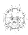
自走式台車としてのパネル組立部40は、図2及び図3に示すように、パネル組立用鋼製支保材41、鋼製支保材上下調整ジャッキ42、鋼製支保材側壁部調整ターンバックル43、鋼製支保材インバート部調整ターンバックル44、ギャードモーター45、駆動伝達チェーン46、走行駆動車輪47等により構成されている。ギャードモーター45の駆動力が駆動伝達チェーン46を介して走行駆動車輪47、47に与えられ自走する。パネル組立部40の機長は、改修用パネル60、61、62長やパネル枚数や組立時の作業能率等により決定される。
As shown in FIGS. 2 and 3, the
パネル支持部50は、図2及び図4に示すように、パネルサポート用鋼製支保材51、鋼製支材上下調整ジャッキ52、鋼製支保材側壁部調整ターンバックル53、鋼製支保材インバート部調整ターンバックル54等により構成されている。パネル支持部50の機長についても、パネル長やパネル枚数及び作業能率等により決定される。
As shown in FIGS. 2 and 4, the
パネル組立部40及びパネル支持部50では、パネル組立用鋼製支保材41またはパネルサポート用鋼製支保材51を仮想線の位置から実線の位置に位置調整しつつ拡張し、パネルを押し当てる。
In the
改修用パネル60、61、62は、坑外からたとえばキャリアダンプ70等で坑内に搬入し、架台30の中央ビーム33内蔵のローラーコンベア34を経由して、パネル組立部40まで搬送する。ローラーコンベア34は、パネル組立部40の近くで、改修用パネルを受取り易いようにたとえば2m位、コンクリート切削機20側(前方)へ移動する構造になっている。図3及び図4に示すように、切削したズリを搬出するベルトコンベア32と改修用パネル60、61、62を搬入するローラーコンベア34は、中央ビーム33内で上下2段の構成になっている。
The
架台30の後方に、裏込材注入ポンプ(図示せず)を設置する。配管を通してパパネル支持部50領域位置に設置する裏込材ノズルへと供給される。
A backing material injection pump (not shown) is installed behind the
以上のように、切削・ズリ運搬、洗浄、パネル組立、パネル支持、裏込材注入及びその定着が終了した時点で、架台30を次のスパンまで、たとえば前述の例では約27m前進し、次の施工を行う。これらの工程が繰り返される。
As described above, when cutting / slipping transportation, cleaning, panel assembly, panel support, backing material injection and fixing are completed, the
10…既設トンネル、20…コンクリート切削機、30…架台、32…ズリ排出搬送路、33…中央ビーム、34…パネル供給搬送路、35…走行用ユニークタイヤ、36…電動ギャードモーター、40…パネル組立部、41…パネル組立用鋼製支保材、50…パネル支持部、51…パネルサポート用鋼製支保材、60、61、62…改修用パネル、70…キャリアダンプ。
DESCRIPTION OF
Claims (5)
架台を進行方向に移動可能に設け、
前記架台に、切削したトンネル内面に改修用パネルを組み立てるためのパネル組立部、並びにその後方にパネル組立て後の改修用パネルを保持するパネル支持部をそれぞれ配置し、
前記架台には、トンネル内面の切削に伴うズリを前方から、前記パネル組立部及びパネル支持部で囲まれる領域内を通って後方に送るズリ排出搬送路、改修用パネルを後方から、前記パネル組立部及びパネル支持部で囲まれる領域内を通って前方に供給するパネル供給搬送路をそれぞれ設け、
進行方向前方において既設トンネル内面を切削し、その切削に伴うズリを前記ズリ排出搬送路を通して前方から前記パネル組立部及びパネル支持部で囲まれる領域内を通って後方に排出し、
改修用パネルをパネル供給搬送路を通して後方から前記パネル支持部及びパネル組立部で囲まれる領域内を通って前方に供給し、
供給された改修用パネルをパネル組立部において切削したトンネル内面に組立て、パネル組立て後の改修用パネルをパネル支持部において保持する、
ことを特徴とするトンネル改修施工方法。 Behind the part that cuts the inner surface of the existing tunnel,
A base is provided to be movable in the direction of travel,
A panel assembly part for assembling a repair panel on the cut tunnel inner surface, and a panel support part for holding the repair panel after panel assembly are arranged behind the panel,
In the gantry, a slip discharge path for sending a slip due to the cutting of the inner surface of the tunnel from the front through a region surrounded by the panel assembly portion and the panel support portion, and a repair panel from the rear are sent from the rear. A panel supply transport path that feeds forward through the area surrounded by the section and the panel support section,
Cutting the inner surface of the existing tunnel in the front in the traveling direction, and discharging the gap accompanying the cutting from the front through the gap discharge conveyance path to the rear through the area surrounded by the panel assembly part and the panel support part,
Supply the panel for repairing from the rear through the panel supply conveyance path through the area surrounded by the panel support part and the panel assembly part, and forward.
Assembling the supplied repair panel on the inner surface of the tunnel cut in the panel assembly part, and holding the repair panel after panel assembly in the panel support part,
Tunnel renovation construction method characterized by this.
前記架台にそれぞれ設けられた、切削したトンネル内面に改修用パネルを組み立てるためのパネル組立部、並びにその後方にパネル組立て後の改修用パネルを保持するパネル支持部と、
前記架台に設けられた、トンネル内面の切削に伴うズリを前方から、前記パネル組立部及びパネル支持部で囲まれる領域内を通って後方に送るズリ排出搬送路と、
前記架台に設けられた、改修用パネルを後方から、前記パネル支持部及びパネル組立部で囲まれる領域内を通って前方に供給するパネル供給搬送路と、を有する
ことを特徴とするトンネル改修施工装置。 A stand provided behind the part that cuts the inner surface of the existing tunnel so as to be able to move by itself in the traveling direction;
A panel assembly part for assembling a repair panel on the inner surface of the cut tunnel provided on each of the mounts, and a panel support part for holding the repair panel after panel assembly behind the panel assembly part,
A slip discharge conveying path that is provided on the pedestal and that sends a slip associated with the cutting of the inner surface of the tunnel from the front through a region surrounded by the panel assembly portion and the panel support portion, and
Provided on the frame, the renovation panel from the rear, tunnel renovation construction, characterized in that it has a, and supplies the panel supply conveyance path forward through the inside of the region surrounded by the panel supporting part and the panel assembly apparatus.
Priority Applications (1)
| Application Number | Priority Date | Filing Date | Title |
|---|---|---|---|
| JP2004241870A JP4340743B2 (en) | 2004-08-23 | 2004-08-23 | Tunnel repair method and repair equipment |
Applications Claiming Priority (1)
| Application Number | Priority Date | Filing Date | Title |
|---|---|---|---|
| JP2004241870A JP4340743B2 (en) | 2004-08-23 | 2004-08-23 | Tunnel repair method and repair equipment |
Publications (3)
| Publication Number | Publication Date |
|---|---|
| JP2006057370A JP2006057370A (en) | 2006-03-02 |
| JP2006057370A5 JP2006057370A5 (en) | 2007-08-09 |
| JP4340743B2 true JP4340743B2 (en) | 2009-10-07 |
Family
ID=36105071
Family Applications (1)
| Application Number | Title | Priority Date | Filing Date |
|---|---|---|---|
| JP2004241870A Active JP4340743B2 (en) | 2004-08-23 | 2004-08-23 | Tunnel repair method and repair equipment |
Country Status (1)
| Country | Link |
|---|---|
| JP (1) | JP4340743B2 (en) |
Families Citing this family (3)
| Publication number | Priority date | Publication date | Assignee | Title |
|---|---|---|---|---|
| CN106988762B (en) * | 2017-05-11 | 2023-08-01 | 四川省创力隧道机械设备有限公司 | Full-section two-lining inverted arch shield equipment |
| CN109505630B (en) * | 2019-01-14 | 2023-09-08 | 中铁一局集团有限公司 | Full-hydraulic crawler-type self-propelled trestle and construction method |
| CN112761671B (en) * | 2020-12-31 | 2023-01-31 | 中铁二院工程集团有限责任公司 | Energy-absorbing and pressure-reducing tunnel bottom pile plate structure and construction method |
-
2004
- 2004-08-23 JP JP2004241870A patent/JP4340743B2/en active Active
Also Published As
| Publication number | Publication date |
|---|---|
| JP2006057370A (en) | 2006-03-02 |
Similar Documents
| Publication | Publication Date | Title |
|---|---|---|
| WO2018082714A1 (en) | Shield tunneling machine for tunnel connecting passageway and connecting passageway tunneling method thereof | |
| JP4340743B2 (en) | Tunnel repair method and repair equipment | |
| JP6715667B2 (en) | Reconstruction method for lining of existing 2-lane road tunnel | |
| JP2006057370A5 (en) | ||
| JP2006016960A (en) | Starting method for shield machine for tunnel construction method | |
| JP4391910B2 (en) | Renovation construction method and equipment for existing waterway tunnel | |
| JP2899880B1 (en) | Tunnel construction equipment | |
| JP5315555B2 (en) | Continuously installed belt conveyor, underpass structure building construction apparatus including the belt conveyor, and element towing excavation method using the underpass structure building construction apparatus | |
| JP5705672B2 (en) | Reconstruction promotion method and equipment for existing pipes | |
| JP4698459B2 (en) | Construction method for underground structures | |
| CN210829276U (en) | Shield does not have burden ring and begins structure | |
| JP2006045978A5 (en) | ||
| JP5577284B2 (en) | Tunnel lining back surface filling method and tunnel lining back surface filling device | |
| JP2898818B2 (en) | Tunnel construction method | |
| JP3398644B2 (en) | How to repair tunnel lining concrete | |
| JP5854808B2 (en) | Rehabilitation of existing pipelines | |
| JP5716535B2 (en) | Disassembly method of shield machine | |
| JPH07217398A (en) | Telpher | |
| KR100558940B1 (en) | Excavating apparatus and excavating method using the same | |
| KR20170091054A (en) | System spreading sand to circle zone and apparatus spreading sand to circle zone and method spreading sand thereof | |
| JP5688274B2 (en) | Pipe installation device | |
| US9631491B2 (en) | Apparatus for forming an underground tunnel | |
| JP6840442B2 (en) | Equipment transportation mechanism in the shield mine | |
| KR20110005147A (en) | Construction method of steel pipe | |
| JP2022122668A (en) | Concrete cutting machine, and existing lining concrete cutting method |
Legal Events
| Date | Code | Title | Description |
|---|---|---|---|
| A521 | Written amendment |
Free format text: JAPANESE INTERMEDIATE CODE: A523 Effective date: 20070621 |
|
| A621 | Written request for application examination |
Free format text: JAPANESE INTERMEDIATE CODE: A621 Effective date: 20070621 |
|
| A977 | Report on retrieval |
Free format text: JAPANESE INTERMEDIATE CODE: A971007 Effective date: 20090527 |
|
| TRDD | Decision of grant or rejection written | ||
| A01 | Written decision to grant a patent or to grant a registration (utility model) |
Free format text: JAPANESE INTERMEDIATE CODE: A01 Effective date: 20090605 |
|
| A711 | Notification of change in applicant |
Free format text: JAPANESE INTERMEDIATE CODE: A711 Effective date: 20090609 |
|
| A01 | Written decision to grant a patent or to grant a registration (utility model) |
Free format text: JAPANESE INTERMEDIATE CODE: A01 |
|
| A61 | First payment of annual fees (during grant procedure) |
Free format text: JAPANESE INTERMEDIATE CODE: A61 Effective date: 20090609 |
|
| FPAY | Renewal fee payment (event date is renewal date of database) |
Free format text: PAYMENT UNTIL: 20120717 Year of fee payment: 3 |
|
| R150 | Certificate of patent or registration of utility model |
Ref document number: 4340743 Country of ref document: JP Free format text: JAPANESE INTERMEDIATE CODE: R150 Free format text: JAPANESE INTERMEDIATE CODE: R150 |
|
| FPAY | Renewal fee payment (event date is renewal date of database) |
Free format text: PAYMENT UNTIL: 20120717 Year of fee payment: 3 |
|
| FPAY | Renewal fee payment (event date is renewal date of database) |
Free format text: PAYMENT UNTIL: 20130717 Year of fee payment: 4 |
|
| FPAY | Renewal fee payment (event date is renewal date of database) |
Free format text: PAYMENT UNTIL: 20130717 Year of fee payment: 4 |
|
| FPAY | Renewal fee payment (event date is renewal date of database) |
Free format text: PAYMENT UNTIL: 20140717 Year of fee payment: 5 |