JP4340027B2 - Cylinder lock compatible gate - Google Patents
Cylinder lock compatible gate Download PDFInfo
- Publication number
- JP4340027B2 JP4340027B2 JP2001210680A JP2001210680A JP4340027B2 JP 4340027 B2 JP4340027 B2 JP 4340027B2 JP 2001210680 A JP2001210680 A JP 2001210680A JP 2001210680 A JP2001210680 A JP 2001210680A JP 4340027 B2 JP4340027 B2 JP 4340027B2
- Authority
- JP
- Japan
- Prior art keywords
- lock
- cylinder lock
- box
- vertical frame
- mounting
- Prior art date
- Legal status (The legal status is an assumption and is not a legal conclusion. Google has not performed a legal analysis and makes no representation as to the accuracy of the status listed.)
- Expired - Fee Related
Links
Images


Landscapes
- Gates (AREA)
Description
【0001】
【発明の属する技術分野】
本発明は、シリンダー錠を取り付けることができるシリンダー錠対応門扉に関する。
【0002】
【従来の技術】
従来、門扉にシリンダー錠を取り付ける場合には、シリンダー錠が収まる幅の縦枠にシリンダー錠を直接取り付けていた。また、門扉は、縦枠と横枠とが溶接された一体構造になっているものが一般的であった。
【0003】
【発明が解決しようとする課題】
しかし、上記した従来技術では、シリンダー錠が収まる幅の縦枠を使用していたため縦枠の幅が広く、材料及び製造コストが嵩むとともに、縦枠の重量が大きいので運搬及び設置に大きな労力を要していた。
【0004】
また、格子状のパネルを使用した門扉においては、シリンダー錠が露出すると美観が損なわれる虞があるため、シリンダー錠を採用するのは困難であった。さらに、シリンダー錠は、種々のサイズのものが製造されているため、個々のサイズのシリンダー錠に合わせて門扉に取り付ける構成をとる必要があった。
【0005】
さらに、縦枠と横枠とが溶接された一体構造になっていると、門扉のサイズが合わない場合に、現場でサイズ調整をするのは容易ではなかった。
【0006】
また、格子状のパネルを使用した門扉にシリンダー錠を取り付けた場合、格子の間隙から裏側へ手を入れてシリンダー錠を開錠することができるといった問題もある。
【0007】
本発明はこうした問題点を解決するためになされたもので、種々のシリンダー錠を簡易かつ安価に取り付けることができ、かつ枠体のサイズ調整が容易で防犯上優れたシリンダー錠対応門扉を提供することを目的とする。
【0008】
【課題を解決するための手段】
上記の目的を達成するため本発明は、相対向する一対の縦枠と少なくとも一対の横枠とが組立及び分解可能に組まれた枠体にパネルが取り付けられてなる門扉において、いずれか一方の縦枠に錠ボックス取付用開口部が縦枠を貫通するように形成され、シリンダー錠を収容した錠ボックスが上記錠ボックス取付用開口部から上記縦枠に装着され、この錠ボックスを介してシリンダー錠が門扉に取り付けられるように構成されたシリンダー錠対応門扉であって、上記シリンダー錠はシリンダー錠本体とこのシリンダー錠本体の一側面が長手方向に延出された錠延出部とからなり、上記錠ボックスはボックス本体とこのボックス本体の一側面が長手方向に延出されたボックス延出部とからなり、シリンダー錠を錠ボックスに収容したときにこれらの錠延出部とボックス延出部が互いに重なるようになされており、上記錠ボックス取付用開口部よりも大きな平板で構成された、上記シリンダー錠を縦枠に取り付けるための第1取付プレートと、錠ボックスを縦枠に取り付けるための第2取付プレートとを備え、この第1取付プレートには、シリンダー錠を挿入可能な開口部が形成されるとともにシリンダー錠の錠延出部を係止してシリンダー錠を保持するストッパが形成され、第2取付プレートには、ボックス本体を挿入可能な開口部が形成されるとともに錠ボックスの下端部を支持する支持部が形成され、上記シリンダー錠の錠延出部と錠ボックスのボックス延出部との間に第1取付プレートのストッパを挟んで縦枠に固定することによりシリンダー錠を第1取付プレートに取り付けるとともに第1取付プレートを縦枠に取り付けてから、縦枠の第1取付プレート取付側の背面側に第2取付プレートを取り付けて錠ボックスを固定し、第1取付プレートおよび第2取付プレートを介して上記シリンダー錠を収容した錠ボックスが上記錠ボックス取付用開口部から上記縦枠に装着されるとともに、上記錠ボックス取付用開口部が第1取付プレートおよび第2取付プレートによって被覆されることを特徴とする。
【0009】
この発明によれば、枠体を縦枠と横枠とに適宜、分解し、組み立てることができる。また、シリンダー錠を錠ボックスに収容して錠ボックス取付用開口部から挿入することによりシリンダー錠を縦枠に取り付けることができる。
【0010】
本発明は、上記第1取付プレートは縦長の長方形状の平板で構成され、上記ストッパはシリンダー錠を挿入する開口部の上縁および下縁が内方へ向かってL字状に屈曲されて形成されていることを特徴とする。
【0012】
本発明は、上記門扉に装着された錠ボックスの周辺部に、この周辺部をカバーするシリンダー錠プレートが配設されていることを特徴とする。
【0013】
この発明によれば、錠ボックスの周辺部をカバーすることができる。
【0014】
本発明は、上記シリンダー錠プレートには、上記錠ボックスの奥行き方向に阻止片が付加されていることを特徴とする。
【0015】
この発明によれば、錠ボックスの周辺部及び上ボックスの奥行き方向をカバーすることができる。
【0016】
【実施の形態】
以下、本発明の実施の形態について図を参照して説明する。
【0017】
図1は本実施の形態に係るシリンダー錠対応門扉1(以下、「門扉1」という。)の全体を示す図、図2は、縦枠2と横枠3の取付構造を示す分解斜視図、図3乃至図6は縦枠2と横枠3の取付構造のバリエーションを示す図、図7乃至図10は錠ボックス5とこの錠ボックス5を取り付けるための部材を示す図、図11乃至図13は錠ボックス5を取り付ける手順を示す図である。
【0018】
本実施の形態に係る門扉1は、一対の縦枠2と少なくとも一対の横枠3とが組立及び分解可能に組まれた枠体に格子状のパネル7が取り付けられ、いずれか一方の縦枠2に形成された錠ボックス取付用開口部20と、シリンダー錠4と、このシリンダー錠4を収容する錠ボックス5とから主要部が構成される。以下、順次上記の各構成部分について説明する。
【0019】
縦枠2と横枠3とは、図2に示すように全体として四角形状に組まれている。一対の縦枠2の相対向する面には、長手方向に所定間隔をおいて複数個の取付部材21が配設されており、この取付部材21に横枠3が挿入されてボルト210で止められており、適宜、分解及び組み立てできるようになされている。
【0020】
なお、この縦枠2と横枠3との取付構造は上記したものに限られるものではない。例えば、図3乃至図5に示す構造によっても好適に取り付けられる。以下それぞれの取付構造について説明する。
【0021】
図3に示す取付構造は、取付部材21の内面に突起211を設けたものである。この突起211により、横枠3を仮固定することができるので、ボルト210を止める際、一括して行なうことができ、組み立て易くなる。
【0022】
図4に示す取付構造は、横枠3の先端縁にネジ穴付キャップ31を取り付け、縦枠2に形成した貫通穴231にボルト210を介して固定するものである。ここで、ネジ穴付キャップ31の横枠3への取り付けは、嵌合によっても良く、また、溶接によっても良い。この取付構造によれば、縦枠2に取付部材21を溶接等によって取り付けるよりも加工が簡単で、加工費を削減することができる。
【0023】
図5に示す取付構造は、一方の縦枠2に横枠3を溶接によって予め取り付けておき、片持ち状態とされた横枠3の端部に縦枠2を取り付けるものである。
なお、図5のように一方の縦枠2にすべての横枠3を予め取り付けておいても良いが、一部の横枠3を一方の縦枠2に取り付け、残りの横枠3を他方の縦枠2に取り付けても良い。この取付構造によれば、組み立て工程を簡素化することができる。
【0024】
いずれか一方の縦枠2には、長手方向略中央部に錠ボックス取付用開口部20が形成されている。なお、他方の縦枠2にはヒンジ部材82が取り付けられており、このヒンジ部材82が門柱8に取り付けられたヒンジ部材81と係合して、門柱8を中心として回動することにより門扉1が開閉自在となるようになされている(図2参照)。
【0025】
錠ボックス取付用開口部20は、開口面が長方形をなし、後述する錠ボックス5がこの開口部20から挿入できるように図られている。この錠ボックス取付用開口部20は、大きいサイズのシリンダー錠が納まる大きさに形成されており、種類の異なるシリンダー錠であっても適応できるように図られている。なお、この錠ボックス取付用開口部20は、角柱の縦枠2のみならず、丸柱の縦枠2であっても形成することができる(図6参照)。丸柱の縦枠2に形成する場合は、縦枠2の一部を平面状に加工してから角穴をあけることにより、錠ボックス取付用開口部20を形成する。
【0026】
シリンダー錠4は、市販されているシリンダー錠であって、図11(a)に示すように、ー側面が長手方向に延出されて錠延出部43とされた形状の取付体42にシリンダー錠本体41が取り付けられている。なお、ここで取付体42に取り付けられているのは、シリンダー錠本体41のみであって、鍵穴、サムターン、レバーハンドル等は後に取り付けられる。
【0027】
錠ボックス5は、シリンダー錠4を収容して錠ボックス取付用開口部20から縦枠2に取り付けるためのものである。この錠ボックス5は、図7に示すように、円形の錠穴51が表面(錠ボックス5がパネル7と接する側の面)と裏面を貫通して設けられた筐体であって、この錠穴51にシリンダー錠本体41が取り付けられている。また、錠ボックス5は、ボックス本体52と、ボックス本体52の一側面が長手方向に延出されたボックス延出部53とから構成されている。なお、錠ボックス5は表裏対称に形成されており、右開き若しくは左開きのいずれの門扉に対しても使用することができる。また、錠ボックス5は、シリンダー錠4の種類に合わせて製造されている。
【0028】
シリンダー錠4と錠ボックス5とを縦枠2に取り付けるために、第1取付プレート61および第2取付プレート62が用いられている。
【0029】
第1取付プレート61は、縦枠2の錠ボックス取付用開口部20を被覆するとともにシリンダー錠4・錠ボックス5を取り付けるためのものである。この第1取付プレート61は図8に示すように、ボックス取付用開口部20よりも大きい平板である。第1取付プレート61には、シリンダー錠4の錠延出部43が嵌め込まれる大きさの開口部610が形成されているとともに、この開口部610を挟んでストッパー611がそれぞれ形成されている。このストッパー611が、開口部610から嵌め込まれたシリンダー錠4の錠延出部43を係止するように図られている。
【0030】
第2取付プレート62は、縦枠2の錠ボックス取付用開口部20を被覆するとともに錠ボックス5を着実に取り付けるためのものである。この第2取付プレート62は、図9に示すように、錠ボックス取付用開口部20よりも大きい平板である。第2取付プレート62には、錠ボックス5のボックス本体52が挿入される開口部620が形成されているとともに、この開口部620の一側端に支持部621が第2取付プレート62に対して鉛直に形成されている。この支持部621が、錠ボックス5が取り付けられた際にボックス本体52と当接し、支持部621とボックス本体52とがボルトを介して固定されるように図られている。なお、サイズの異なる錠ボックス5に対しては、その錠ボックス5に適合する第1取付プレート61及び第2取付プレート62を製作すれば、錠ボックス取付用開口部20は好適に被覆される。
【0031】
また、門扉1に取り付けられた錠ボックス5の周辺部には、シリンダー錠プレート63が配設されている(図10参照)。このシリンダー錠プレート63は、錠ボックス5の周辺部をカバーして格子パネル7の間隙から裏側へ手を入れてシリンダー錠4を開錠するのを防止するためのものである。このシリンダー錠プレート63は、錠ボックス5の表面よりも大きく形成されるとともに、錠穴51と一致する開口部630が形成された平板である。
【0032】
このシリンダー錠プレート63には、錠ボックス5の奥行き方向に阻止片631が付加されていても良い(図16参照)。上記したシリンダー錠4の開錠をより確実に防止するためには、シリンダー錠プレート63を大きくすれば良いが、あまり大きくすると、門扉1の外観が損なわれる。このため、この阻止片631は、シリンダー錠プレート63の大きさを変えずに開錠を防止するために用いられるものである。阻止片631は、図16(b)に示すように、錠ボックス5の厚さよりも若干厚くなされ、両端が同方向に折曲された板状体の部材であって、一方の端部がシリンダー錠プレート63の端縁にボルト632を介して取り付けられている。なお、この阻止片631とシリンダー錠プレート63とは、一体的に形成されていても良い。
【0033】
次に上記構成の錠ボックス5の取り付け方法について図8乃至図13を参照しながら説明する。
【0034】
まず第1取付プレート61の開口部610からシリンダー錠4を挿入し、シリンダー錠4の錠延出部43がストッパー611と係止するまで嵌め込む。次いで、シリンダー錠4を錠ボックス5に挿入し、シリンダー錠本体41と錠ボックスの錠穴51とを一致させる。次いで、シリンダー錠4を挿入した錠ボックス5を一方の縦枠2の錠ボックス取付用開口部20から挿入し、これらのシリンダー錠4、第1取付プレート61及び錠ボックス5を、ボルトを介して固定する。(図11( a) 参照)。
【0035】
次に、第2取付プレート62の開口部620に錠ボックス5のボックス本体52を挿入して、第2取付プレート62を縦枠2の第1取付プレート61取付側の背面側に取り付ける。この際、錠ボックス5は第2取付プレート62の支持部621に当接するので、支持部621と錠ボックスとをボルトを介して固定する。(図11(b)参照)。
【0036】
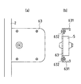
続いて、シリンダー錠プレート63を錠ボックス5の表面側に取り付ける( 図11(c)参照)。なお、上記した部材はいずれもボルトを介して固定しており、また、鍵穴やラッチボルト、サムターン、レバーハンドルなどは、これらの部材を固定した後に取り付ける(図13参照)。
【0037】
錠ボックス5が取り付けられた門扉1を受ける側の門扉(両開きの場合)の該縦枠2に対向する縦枠若しくは門柱(片開きの場合)には、縦枠2の錠ボックス取付用開口部20と同様の大きさの開口部200が形成されており、この開口部200を覆う受け側プレート64が設けられている(図12参照)。この受け側プレート64には長手方向中央部に角穴640が形成されており、この角穴640に縦枠2に設けられたラッチボルトが挿入されるように図られている。したがって、この角穴640をシリンダー錠4の種類に合わせて変えることにより、受け側プレート64が設けられた縦枠若しくは門柱は、一種類で多種類のシリンダー錠4に対応することができる。なお、上記した両開きの門扉の場合、門扉1に対向する門扉には、シリンダー錠プレート63に対応する位置にシリンダー錠プレート63と同様な大きさのプレート65が配設され、シリンダー錠プレート63とともに、格子パネルの間隙から裏側へ手を入れてシリンダー錠4を開錠するのを防止するように図られている。
【0038】
次に、本発明の他の実施の形態について図14及び図15を参照しながら説明する。
【0039】
この実施の形態は、縦枠2に開口部を形成することなく、錠ボックス5を取り付けるものである。したがって、上記した実施の形態と縦枠2に錠ボックスを取り付ける形態のみが異なり、他は共通しているので、異なる部分のみ説明する。
【0040】
図14に示す例は、錠ボックス5にネジ穴500を形成し、ボルト501を介して縦枠2に取り付けるものである。なお、この場合、錠ボックス5には、ボックス延出部53を設けない。
【0041】
また、図15に示す例は、縦枠2を長手方向に2つに分割し、これらの分割した縦枠2の間に錠ボックス5を挟み込み、錠ボックスのボックス延出部53を縦枠2に取り付けるものである。
【0042】
【発明の効果】
以上に説明したとおり、本発明のシリンダー錠対応門扉は、相対向する一対の縦枠と少なくとも一対の横枠とが組立及び分解可能に組まれた枠体にパネルを取り付けてなる門扉であって、いずれか一方の縦枠に、シリンダー錠を収容した錠ボックスが装着され、この錠ボックスを介してシリンダー錠が門扉に取り付けられることを特徴とするので、枠体を縦枠と横枠とに適宜、分解し、組み立てることができる。また、縦枠にシリンダー錠を収容した錠ボックスを取り付けることができる。したがって、縦枠に特殊な加工を必要とせず、低コストでシリンダー錠を取り付けることができる。 また、錠ボックスにシリンダー錠を収容しているので、シリンダー錠が外部に露出することがなく、美観に優れている。
【0043】
また、いずれか一方の縦枠に錠ボックス取付用開口部を形成し、シリンダー錠を収容した錠ボックスを錠ボックス取付用開口部から上記縦枠に装着し、この錠ボックスを介してシリンダー錠を門扉に取り付ける構成なので、シリンダー錠を錠ボックスに収容して錠ボックス取付用開口部から挿入することによりシリンダー錠を縦枠に取りつけることができる。
【0044】
したがって、種類の異なるシリンダー錠であっても、そのシリンダー錠に対応する錠ボックスに収容して錠ボックス取付用開口部から縦枠に取り付けることができ、同じ縦枠を使用して門扉を製造することができるので、製造コストを削減することができる。また、縦枠に直接シリンダー錠を取り付ける必要がないので、縦枠の幅を薄くすることができ、非常に安価であって、かつ軽量なので運搬及び設置作業が容易である。
【0045】
さらに、門扉の枠体は縦枠と横枠とが組立及び分解可能に組まれてなっているので、枠を適宜切断して再度組み立てることによりサイズを調整することができ、現場でも簡単に行うことができる。
【0046】
また、門扉に装着された錠ボックスの周辺部に、この周辺部をカバーするシリンダー錠プレートを配設した場合は、錠ボックスの周辺部をカバーすることができる。したがって、格子パネルの間隙から裏側へ手を入れてシリンダー錠を開錠するの防止することができる
上記の構成において、シリンダー錠プレートに、錠ボックスの奥行き方向に阻止片を付加した場合は、錠ボックスの周辺部及び上ボックスの奥行き方向をカバーすることができる。したがって、上記したシリンダー錠4の開錠をより確実に防止することができる。
【図面の簡単な説明】
【図1】本発明の実施の形態に係るシリンダー錠対応門扉の全体を示す図である。
【図2】縦枠と横枠の取付構造を示す分解斜視図である。
【図3】縦枠と横枠の他の取付構造を示す図である。
【図4】縦枠と横枠の他の取付構造を示す図である。
【図5】縦枠と横枠の他の取付構造を示す図である。
【図6】縦枠の他の形態を示す図である。
【図7】錠ボックスの構造を示し、(a)は正面図、(b)は側面図、(c)は底面図である。
【図8】第1取付プレートの構造を示し、(a)は平面図、(b)は側面図である。
【図9】第2取付プレートの構造を示し、(a)は平面図、(b)は側面図である。
【図10】シリンダー錠プレートの取り付け状態を示す図である。
【図11】錠ボックスの取り付け手順を示す図である。
【図12】受け側プレートの構造を示す図である。
【図13】錠ボックスの取り付け手順を示す図である。
【図14】他の実施の形態に係る錠ボックスの取付構造を示す図である。
【図15】他の実施の形態に係る錠ボックスの取付構造を示す図である。
【図16】シリンダー錠プレートの他の形態を示し、(a)は平面図、(b)は断面図である。
【符号の説明】
1 シリンダー錠対応門扉
2 縦枠
20 錠ボックス取付用開口部
3 横枠
4 シリンダー錠
5 錠ボックス
63 シリンダー錠プレート
631阻止片
7 パネル[0001]
BACKGROUND OF THE INVENTION
The present invention relates to a cylinder over lock corresponding gates that can be attached to the lock cylinder.
[0002]
[Prior art]
Conventionally, when a cylinder lock is attached to a gate door, the cylinder lock is directly attached to a vertical frame that fits in the cylinder lock. Further, the gate is generally an integral structure in which a vertical frame and a horizontal frame are welded.
[0003]
[Problems to be solved by the invention]
However, in the above-described prior art, a vertical frame having a width that can accommodate the cylinder lock is used, so that the width of the vertical frame is wide, the material and manufacturing cost increase, and the weight of the vertical frame is large. It was necessary.
[0004]
Moreover, in the gate door using a grid | lattice-like panel, since there exists a possibility that the beauty | look may be impaired when a cylinder lock is exposed, it was difficult to employ | adopt a cylinder lock. Furthermore, since cylinder locks of various sizes are manufactured, it is necessary to adopt a configuration in which the cylinder lock is attached to the gate according to the cylinder lock of each size.
[0005]
Furthermore, when the vertical frame and the horizontal frame are welded and integrated, it is not easy to adjust the size on site if the size of the gate does not match.
[0006]
In addition, when the cylinder lock is attached to the gate using a grid-like panel, there is a problem that the cylinder lock can be unlocked by putting a hand into the back side through the gap of the grid.
[0007]
The present invention has been made to solve these problems, and provides a cylinder lock-compatible gate that can be easily and inexpensively attached with various cylinder locks and that is easy to adjust the size of the frame and is excellent in crime prevention. For the purpose.
[0008]
[Means for Solving the Problems]
The present invention for achieving the object of the Te opposing pair of vertical frame with at least a pair of gates odor and transverse frame formed by panels attached to the frame bodies assembled in the assembly and possible disassembly, either one The lock box mounting opening is formed in the vertical frame so as to penetrate the vertical frame, and the lock box containing the cylinder lock is mounted on the vertical frame from the lock box mounting opening, A cylinder lock-compatible gate configured so that the cylinder lock can be attached to the gate . The cylinder lock includes a cylinder lock body and a lock extending portion in which one side surface of the cylinder lock body extends in the longitudinal direction. The lock box is composed of a box body and a box extending portion in which one side surface of the box body extends in the longitudinal direction. When the cylinder lock is accommodated in the lock box, Tablets are extending portion and the box extending portion is made to overlap one another, composed of a large flat plate than the lock box mounting opening portion, a first mounting plate for mounting the cylinder lock in the vertical frame, And a second mounting plate for mounting the lock box to the vertical frame. The first mounting plate is formed with an opening through which the cylinder lock can be inserted, and the lock extending portion of the cylinder lock is locked. A stopper for holding the cylinder lock is formed, and an opening through which the box body can be inserted is formed in the second mounting plate, and a support portion for supporting the lower end of the lock box is formed. The cylinder lock is attached to the first mounting plate by fixing the stopper of the first mounting plate between the protruding portion and the box extending portion of the lock box to the vertical frame. From both attaching the first mounting plate to the vertical frame, the back side of the first mounting plate mounting side of the vertical frame by attaching the second mounting plate to fix the lock box, via the first mounting plate and a second mounting plate The lock box containing the cylinder lock is mounted on the vertical frame from the lock box mounting opening, and the lock box mounting opening is covered by the first mounting plate and the second mounting plate. Features.
[0009]
According to this invention, a frame can be appropriately disassembled into a vertical frame and a horizontal frame and assembled. Moreover, a cylinder lock can be attached to a vertical frame by accommodating a cylinder lock in a lock box, and inserting from a lock box attachment opening part .
[0010]
In the present invention, the first mounting plate is formed of a vertically long rectangular flat plate, and the stopper is formed by bending the upper and lower edges of the opening for inserting the cylinder lock in an L shape inward. It has been characterized by Rukoto.
[0012]
The present invention is characterized in that a cylinder lock plate that covers the periphery of the lock box mounted on the gate is disposed.
[0013]
According to this invention, the peripheral part of a lock box can be covered.
[0014]
The present invention is characterized in that a blocking piece is added to the cylinder lock plate in the depth direction of the lock box.
[0015]
According to this invention, it is possible to cover the peripheral portion of the lock box and the depth direction of the upper box .
[0016]
Embodiment
Hereinafter, embodiments of the present invention will be described with reference to the drawings.
[0017]
FIG. 1 is an overall perspective view of a cylinder lock-compatible gate 1 (hereinafter referred to as “
[0018]
In the
[0019]
As shown in FIG. 2, the
[0020]
The mounting structure of the
[0021]
In the mounting structure shown in FIG. 3, a
[0022]
The attachment structure shown in FIG. 4 attaches the
[0023]
The attachment structure shown in FIG. 5 attaches the
Although all the
[0024]
One of the
[0025]
The
[0026]
The
[0027]
The
[0028]
In order to attach the
[0029]
The
[0030]
The
[0031]
A
[0032]
A blocking
[0033]
Next, a method for attaching the
[0034]
First, the
[0035]
Next, the
[0036]
Subsequently, the
[0037]
The lock box mounting opening of the
[0038]
Next, another embodiment of the present invention will be described with reference to FIGS.
[0039]
In this embodiment, the
[0040]
In the example shown in FIG. 14, screw holes 500 are formed in the
[0041]
In the example shown in FIG. 15, the
[0042]
【The invention's effect】
As described above, cylinder lock corresponding gates of the present invention, there in gates in which the pair of vertical frames which faces and at least a pair of lateral frame is mounted a panel in the assembly and disassembly possible braided frame A lock box containing a cylinder lock is attached to one of the vertical frames, and the cylinder lock is attached to the gate through this lock box. If necessary, it can be disassembled and assembled. Moreover, the lock box which accommodated the cylinder lock in the vertical frame can be attached. Therefore, no special processing is required for the vertical frame, and the cylinder lock can be attached at low cost. Moreover, since the cylinder lock is accommodated in the lock box, the cylinder lock is not exposed to the outside, and the appearance is excellent.
[0043]
Also, a lock box mounting opening is formed in one of the vertical frames, and a lock box containing a cylinder lock is attached to the vertical frame from the lock box mounting opening, and the cylinder lock is inserted through the lock box. Since it is the structure attached to a gate, a cylinder lock can be attached to a vertical frame by accommodating a cylinder lock in a lock box, and inserting from a lock box attachment opening part.
[0044]
Therefore, even different types of cylinder locks can be accommodated in the lock box corresponding to the cylinder lock and attached to the vertical frame from the lock box mounting opening, and the gate is manufactured using the same vertical frame. Manufacturing cost can be reduced. Further, since it is not necessary to attach the cylinder lock directly to the vertical frame, the width of the vertical frame can be reduced, and it is very inexpensive and lightweight, so that it can be easily transported and installed.
[0045]
Furthermore, since the frame of the gate is assembled so that the vertical frame and the horizontal frame can be assembled and disassembled, the size can be adjusted by cutting and reassembling the frame as appropriate, and it is easily performed on site. be able to.
[0046]
Moreover, when the cylinder lock plate which covers this peripheral part is arrange | positioned in the peripheral part of the lock box with which the gate door was mounted | worn, the peripheral part of a lock box can be covered. Therefore, in the above configuration in which it is possible to prevent the cylinder lock from being unlocked by putting the hand from the gap between the lattice panels, when a blocking piece is added to the cylinder lock plate in the depth direction of the lock box, The peripheral part of the box and the depth direction of the upper box can be covered. Therefore, the above-described unlocking of the
[Brief description of the drawings]
FIG. 1 is a diagram showing an entire cylinder lock-compatible gate according to an embodiment of the present invention.
FIG. 2 is an exploded perspective view showing a mounting structure of a vertical frame and a horizontal frame.
FIG. 3 is a view showing another mounting structure of a vertical frame and a horizontal frame.
FIG. 4 is a view showing another mounting structure of a vertical frame and a horizontal frame.
FIG. 5 is a view showing another mounting structure of a vertical frame and a horizontal frame.
FIG. 6 is a diagram showing another form of the vertical frame.
7A and 7B show the structure of a lock box, where FIG. 7A is a front view, FIG. 7B is a side view, and FIG. 7C is a bottom view.
8A and 8B show the structure of the first mounting plate, where FIG. 8A is a plan view and FIG. 8B is a side view.
9A and 9B show the structure of the second mounting plate, where FIG. 9A is a plan view and FIG. 9B is a side view.
FIG. 10 is a diagram showing an attached state of the cylinder lock plate.
FIG. 11 is a diagram showing a procedure for attaching a lock box.
FIG. 12 is a view showing a structure of a receiving side plate.
FIG. 13 is a diagram showing a procedure for attaching a lock box.
FIG. 14 is a view showing a lock box mounting structure according to another embodiment.
FIG. 15 is a view showing a lock box mounting structure according to another embodiment;
16A and 16B show another embodiment of the cylinder lock plate, wherein FIG. 16A is a plan view and FIG. 16B is a cross-sectional view.
[Explanation of symbols]
1 Gate for
Claims (4)
上記シリンダー錠はシリンダー錠本体とこのシリンダー錠本体の一側面が長手方向に延出された錠延出部とからなり、上記錠ボックスはボックス本体とこのボックス本体の一側面が長手方向に延出されたボックス延出部とからなり、シリンダー錠を錠ボックスに収容したときにこれらの錠延出部とボックス延出部が互いに重なるようになされており、
上記錠ボックス取付用開口部よりも大きな平板で構成された、上記シリンダー錠を縦枠に取り付けるための第1取付プレートと、錠ボックスを縦枠に取り付けるための第2取付プレートとを備え、
この第1取付プレートには、シリンダー錠を挿入可能な開口部が形成されるとともにシリンダー錠の錠延出部を係止してシリンダー錠を保持するストッパが形成され、第2取付プレートには、ボックス本体を挿入可能な開口部が形成されるとともに錠ボックスの下端部を支持する支持部が形成され、
上記シリンダー錠の錠延出部と錠ボックスのボックス延出部との間に第1取付プレートのストッパを挟んで縦枠に固定することによりシリンダー錠を第1取付プレートに取り付けるとともに第1取付プレートを縦枠に取り付けてから、縦枠の第1取付プレート取付側の背面側に第2取付プレートを取り付けて錠ボックスを固定し、
第1取付プレートおよび第2取付プレートを介して上記シリンダー錠を収容した錠ボックスが上記錠ボックス取付用開口部から上記縦枠に装着されるとともに、上記錠ボックス取付用開口部が第1取付プレートおよび第2取付プレートによって被覆されることを特徴とするシリンダー錠対応門扉。Opposed pair of vertical frames to at least a pair of lateral frames Te gates odor comprising panels attached to the frame member are assembled to the assembly and degradable, opening for one tablet box mounted on one of the vertical frame A lock box formed so as to penetrate the vertical frame is installed in the vertical frame from the lock box mounting opening, and the cylinder lock is attached to the gate via the lock box. A cylinder lock compatible gate ,
The cylinder lock is composed of a cylinder lock body and a lock extending portion in which one side surface of the cylinder lock body extends in the longitudinal direction. The lock box extends in the longitudinal direction on one side surface of the box body and the box body. The box extension portion, and when the cylinder lock is accommodated in the lock box, the lock extension portion and the box extension portion overlap each other,
Comprising a first mounting plate for mounting the cylinder lock to the vertical frame, and a second mounting plate for mounting the lock box to the vertical frame, which is composed of a flat plate larger than the lock box mounting opening ;
The first mounting plate is formed with an opening through which the cylinder lock can be inserted, and a stopper for holding the cylinder lock by locking the lock extending portion of the cylinder lock is formed. An opening into which the box body can be inserted is formed and a support part for supporting the lower end of the lock box is formed,
The cylinder lock is attached to the first attachment plate and fixed to the first attachment plate by fixing the stopper of the first attachment plate between the lock extension portion of the cylinder lock and the box extension portion of the lock box and fixing the cylinder lock to the first attachment plate. Is attached to the vertical frame, and then the second mounting plate is attached to the back side of the vertical frame on the first mounting plate mounting side to fix the lock box,
A lock box containing the cylinder lock is mounted on the vertical frame from the lock box mounting opening via the first mounting plate and the second mounting plate, and the lock box mounting opening is the first mounting plate. And a cylinder lock-compatible gate covered with a second mounting plate.
上記第1取付プレートは縦長の長方形状の平板で構成され、上記ストッパはシリンダー錠を挿入する開口部の上縁および下縁が内方へ向かってL字状に屈曲されて形成されていることを特徴とするシリンダー錠対応門扉。A gate for cylinder lock according to claim 1,
The first mounting plate is composed of a vertically long rectangular flat plate, Rukoto the stopper is formed is bent toward the upper edge and the lower edge of the opening for inserting the cylinder lock is inward in an L-shape A cylinder lock compatible gate.
上記門扉に装着された錠ボックスの周辺部に、この周辺部をカバーするシリンダー錠プレートが配設されていることを特徴とするシリンダー錠対応門扉。A cylinder lock-compatible gate according to claim 1 or 2,
The periphery of the mounted lock box above gates, features and be Resid Linder tablets corresponding gates that cylinder lock plate covering the peripheral portion are disposed.
上記シリンダー錠プレートには、上記錠ボックスの奥行き方向に阻止片が付加されていることを特徴とするシリンダー錠対応門扉。A cylinder lock-compatible gate according to claim 3,
A blocking gate for a cylinder lock, wherein a blocking piece is added to the cylinder lock plate in the depth direction of the lock box.
Priority Applications (1)
| Application Number | Priority Date | Filing Date | Title |
|---|---|---|---|
| JP2001210680A JP4340027B2 (en) | 2000-12-04 | 2001-07-11 | Cylinder lock compatible gate |
Applications Claiming Priority (3)
| Application Number | Priority Date | Filing Date | Title |
|---|---|---|---|
| JP2000-369096 | 2000-12-04 | ||
| JP2000369096 | 2000-12-04 | ||
| JP2001210680A JP4340027B2 (en) | 2000-12-04 | 2001-07-11 | Cylinder lock compatible gate |
Publications (3)
| Publication Number | Publication Date |
|---|---|
| JP2002235465A JP2002235465A (en) | 2002-08-23 |
| JP2002235465A5 JP2002235465A5 (en) | 2007-07-05 |
| JP4340027B2 true JP4340027B2 (en) | 2009-10-07 |
Family
ID=26605219
Family Applications (1)
| Application Number | Title | Priority Date | Filing Date |
|---|---|---|---|
| JP2001210680A Expired - Fee Related JP4340027B2 (en) | 2000-12-04 | 2001-07-11 | Cylinder lock compatible gate |
Country Status (1)
| Country | Link |
|---|---|
| JP (1) | JP4340027B2 (en) |
Families Citing this family (5)
| Publication number | Priority date | Publication date | Assignee | Title |
|---|---|---|---|---|
| JP5281361B2 (en) * | 2008-10-30 | 2013-09-04 | Jfe建材フェンス株式会社 | Mounting structure of door vertical frame and cylinder lock |
| JP5096287B2 (en) * | 2008-10-30 | 2012-12-12 | Jfe建材フェンス株式会社 | Cylinder lock box |
| JP5096288B2 (en) * | 2008-10-30 | 2012-12-12 | Jfe建材フェンス株式会社 | Cylinder lock box |
| JP5889608B2 (en) * | 2011-11-17 | 2016-03-22 | 日鐵住金建材株式会社 | Locking device mounting structure |
| JP6050208B2 (en) * | 2013-09-26 | 2016-12-21 | 積水樹脂株式会社 | Gate |
-
2001
- 2001-07-11 JP JP2001210680A patent/JP4340027B2/en not_active Expired - Fee Related
Also Published As
| Publication number | Publication date |
|---|---|
| JP2002235465A (en) | 2002-08-23 |
Similar Documents
| Publication | Publication Date | Title |
|---|---|---|
| EP1092827A2 (en) | Multi point bolting mechanism | |
| JP4340027B2 (en) | Cylinder lock compatible gate | |
| CA2134519A1 (en) | Automobile door striker assembly | |
| JPS6217060B2 (en) | ||
| KR200283418Y1 (en) | Tempered Glass Door Opening and Closing Device | |
| KR20000005499U (en) | Vault Door Locks | |
| JPH0425181Y2 (en) | ||
| JP4429448B2 (en) | How to assemble gate and door locks and gate locks | |
| US3503234A (en) | Sheet metal case for mortise lock | |
| JPH056400Y2 (en) | ||
| JPS5850042Y2 (en) | 3 point door lock | |
| JPH1162337A (en) | Lock receiver for door | |
| JP4182710B2 (en) | Insect repellent container | |
| JPH0732803Y2 (en) | Door unlocking device with door guard function | |
| KR200251204Y1 (en) | A bar-type handle of disital door lock | |
| JP2901971B1 (en) | Protection cover for tower bolts, etc. | |
| JP3058709U (en) | Adjustment structure of door latch receiving bracket | |
| JPS5840195Y2 (en) | Gate lock installation device | |
| JP3453943B2 (en) | Embedded distribution board | |
| JP4235390B2 (en) | Door lock box structure | |
| EP0217994A1 (en) | Device for the reinforcement of the rear wall of a safe compartment, especially in strong-rooms | |
| KR960004219B1 (en) | Microwave oven door | |
| JPH0722478Y2 (en) | Gate lock | |
| CA2541762C (en) | Lock mounting system | |
| US8266935B2 (en) | Lock mounting system |
Legal Events
| Date | Code | Title | Description |
|---|---|---|---|
| A621 | Written request for application examination |
Free format text: JAPANESE INTERMEDIATE CODE: A621 Effective date: 20050922 |
|
| A521 | Request for written amendment filed |
Free format text: JAPANESE INTERMEDIATE CODE: A523 Effective date: 20070517 |
|
| A977 | Report on retrieval |
Free format text: JAPANESE INTERMEDIATE CODE: A971007 Effective date: 20080630 |
|
| A131 | Notification of reasons for refusal |
Free format text: JAPANESE INTERMEDIATE CODE: A131 Effective date: 20080708 |
|
| A521 | Request for written amendment filed |
Free format text: JAPANESE INTERMEDIATE CODE: A523 Effective date: 20080904 |
|
| A131 | Notification of reasons for refusal |
Free format text: JAPANESE INTERMEDIATE CODE: A131 Effective date: 20090203 |
|
| A521 | Request for written amendment filed |
Free format text: JAPANESE INTERMEDIATE CODE: A523 Effective date: 20090402 |
|
| A131 | Notification of reasons for refusal |
Free format text: JAPANESE INTERMEDIATE CODE: A131 Effective date: 20090512 |
|
| A521 | Request for written amendment filed |
Free format text: JAPANESE INTERMEDIATE CODE: A523 Effective date: 20090522 |
|
| TRDD | Decision of grant or rejection written | ||
| A01 | Written decision to grant a patent or to grant a registration (utility model) |
Free format text: JAPANESE INTERMEDIATE CODE: A01 Effective date: 20090616 |
|
| A01 | Written decision to grant a patent or to grant a registration (utility model) |
Free format text: JAPANESE INTERMEDIATE CODE: A01 |
|
| A61 | First payment of annual fees (during grant procedure) |
Free format text: JAPANESE INTERMEDIATE CODE: A61 Effective date: 20090703 |
|
| R150 | Certificate of patent or registration of utility model |
Ref document number: 4340027 Country of ref document: JP Free format text: JAPANESE INTERMEDIATE CODE: R150 |
|
| FPAY | Renewal fee payment (event date is renewal date of database) |
Free format text: PAYMENT UNTIL: 20120710 Year of fee payment: 3 |
|
| FPAY | Renewal fee payment (event date is renewal date of database) |
Free format text: PAYMENT UNTIL: 20120710 Year of fee payment: 3 |
|
| FPAY | Renewal fee payment (event date is renewal date of database) |
Free format text: PAYMENT UNTIL: 20130710 Year of fee payment: 4 |
|
| FPAY | Renewal fee payment (event date is renewal date of database) |
Free format text: PAYMENT UNTIL: 20140710 Year of fee payment: 5 |
|
| LAPS | Cancellation because of no payment of annual fees |