JP4339553B2 - Confocal microscope - Google Patents
Confocal microscope Download PDFInfo
- Publication number
- JP4339553B2 JP4339553B2 JP2002165124A JP2002165124A JP4339553B2 JP 4339553 B2 JP4339553 B2 JP 4339553B2 JP 2002165124 A JP2002165124 A JP 2002165124A JP 2002165124 A JP2002165124 A JP 2002165124A JP 4339553 B2 JP4339553 B2 JP 4339553B2
- Authority
- JP
- Japan
- Prior art keywords
- illumination
- confocal microscope
- optical system
- light
- illumination optical
- Prior art date
- Legal status (The legal status is an assumption and is not a legal conclusion. Google has not performed a legal analysis and makes no representation as to the accuracy of the status listed.)
- Expired - Fee Related
Links
Images


Classifications
-
- G—PHYSICS
- G02—OPTICS
- G02B—OPTICAL ELEMENTS, SYSTEMS OR APPARATUS
- G02B21/00—Microscopes
- G02B21/0004—Microscopes specially adapted for specific applications
- G02B21/002—Scanning microscopes
- G02B21/0024—Confocal scanning microscopes (CSOMs) or confocal "macroscopes"; Accessories which are not restricted to use with CSOMs, e.g. sample holders
- G02B21/0036—Scanning details, e.g. scanning stages
- G02B21/0044—Scanning details, e.g. scanning stages moving apertures, e.g. Nipkow disks, rotating lens arrays
Description
【0001】
【発明の属する技術分野】
本発明は、高いセクショニング効果を持つ共焦点顕微鏡に関する。
【0002】
【従来の技術】
一般に、共焦点顕微鏡は、ディスクスキャン型とレーザー走査型の二種類が良く知られており、この内、ディスクスキャン型共焦点顕微鏡は、通常の顕微鏡と比較して試料の横方向分解能が高いだけでなく、試料の高さ方向(Z方向)に非常に高いセクショニング効果を持つという大きな特徴を有している。そのため、ディスクスキャン型共焦点顕微鏡と画像処理技術とを組み合わせることにより、試料の3次元画像構築が可能であるという優れた特徴を有している。
【0003】
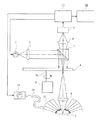
図11は、ディスクスキャン型共焦点顕微鏡の代表的な構成例を示している。このディスクスキャン型共焦点顕微鏡には、目視観察と撮像装置(CCDカメラ)による観察との二通りの観察方法があるが、ここではCCDカメラを用いた例を示している。図に示す如く、光源1から出射した照明光は、コリメターレンズ2を通ってハーフミラー3に入射し、ここで反射されてマスクパターン部材としての回転ディスク4を照明する。この回転ディスク4は、例えばニポウディスクと呼ばれる螺旋状に複数のピンホールが形成されたものであるが、他にスリットパターンが形成されたものも知られている。この回転ディスク4は、モーター5の回転軸5aに取り付けられていて、所定の回転速度で回転される。回転ディスク4に照射された照明光は、回転ディスク4に形成された複数のピンホールを通過し、対物レンズ6により試料7上に結像される。
【0004】
試料7からの反射光は、再び対物レンズ6及び回転ディスク4のピンホールを介してハーフミラー3を透過し、集光レンズ8を通ってCCDカメラ9に入射する。
コンピュータ10は、CCDカメラ9から出力された画像信号を取り込み、画像処理を行って所望の画像データを記憶すると共に、モニタ11に画像を表示する。
【0005】
【発明が解決しようとする課題】
ところで、このディスクスキャン型共焦点顕微鏡においては、回転ディスク4のピンホールを通過した照明光が対物レンズ6を介して試料7を照射し、その反射光が再び対物レンズ6に戻って回転ディスク4のピンホールとハーフミラー3を介して集光レンズ8によりCCDカメラ9上に結像するようになっているため、試料7が図12に示すような三次元構造を有していて、その外面の傾斜角が著しく大きい(急峻である)場合、この傾斜面での反射光は対物レンズ8の開口外へ反射してしまい、対物レンズ8には戻らない。そのため、CCDカメラ9上に形成される像は反射光の不足で非常に暗い像となり、画像にならない恐れがある。この結果、部分的な三次元画像しか構築できないという問題があった。
【0006】
この場合、開口数の大きい対物レンズに切り替えることにより、ある程度までは反射光を対物レンズの開口内に取り込むことは可能であるが、開口数の大きい対物レンズは動作距離が小さいため適用できる試料が限られてしまったり、倍率の制約があったりして様々な試料に使用することは難しい。
【0007】
本発明は、上記の如き従来技術の有する問題点に鑑みてなされたものであり、その目的とするところは、試料の急峻な斜面部分をも観察でき、より正確な三次元画像が構築できる共焦点顕微鏡を提供することにある。
【0008】
【課題を解決するための手段】
上記の目的を達成するため、本発明による共焦点顕微鏡は、落射照明光源と、所定のパターンで光透過部と光遮光部が形成されたマスクパターン部材と、前記落射照明光源からの光を前記マスクパターン部材に導く第1の照明光学系と、前記マスクパターン部材からの光を試料上に照射する対物レンズとを備えた共焦点顕微鏡であって、複数の発光手段によって前記第1の照明光学系の光路とは異なる光路で試料を斜めに照明する第2の照明光学系を備え、前記複数の発光手段の各々が試料上の実質的に一点に向かうように設置されているとともに、前記マスクパターン部材は、前記所定のパターンが形成されたパターン領域と、前記所定のパターンが形成されていない透過領域とからなり、前記パターン領域が第1の照明光学系の光路を通過している期間のみ前記落射照明光源をオンにし、前記透過領域が第1の照明光学系の光路を通過している期間のみ前記複数の発光手段をオンにすることを特徴とする。
また、本発明によれば、上記共焦点顕微鏡は、前記第1の照明光学系からの照明と前記第2の照明光学系からの照明を切り替える切換機構を備えている。
また、本発明によれば、前記パターン領域と前記透過領域の境界線は、前記マスクパターン部材の中心から周辺に向けて形成されている。
また、本発明によれば、前記パターン領域と前記透過領域の境界線は、前記マスクパターン部材の中心に対して同心円状に形成されている。
また、本発明によれば、前記パターン領域は、直線状の光透過部と光遮光部を交互に配置したスリット状に形成されている。
また、本発明によれば、前記第2の照明光学系の発光手段は、発光素子である。
また、本発明によれば、前記第2の照明光学系は、少なくとも一部の領域の前記発光素子を選択的に発光させる。
また、本発明によれば、前記切換機構は、前記第1の照明光学系と第2の照明光学系の少なくとも一方に設けられたシャッターである。
また、本発明によれば、前記第2の照明光学系は、前記対物レンズの光軸に対して傾斜した方向から照明する。
【0009】
【発明の実施の形態】
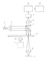
以下、本発明の実施の形態を図示した実施例に基づき説明する。図1は本発明に係る共焦点顕微鏡の第1実施例の構成図である。図中、従来技術で示したのと実質上同一の部材には同一符号が付され、それらについての説明は省略されている。この実施例においては、落射照明光源1から出射した照明光は、コリメーターレンズ2,ハーフミラー3を通して複数のピンホールが形成された回転ディスク4を照射する。回転ディスク4はモータ5により所定の速度で回転せしめられており、回転ディスク4に形成された複数のピンホールを通過した照明光が、対物レンズ6により試料7上に結像される。試料7からの反射光は、再び対物レンズ6,回転ディスク4のピンホールを介してハーフミラー3を透過し、集光レンズ8によりCCDカメラ9に入射せしめられる。コンピュータ10は、CCDカメラ9から出力される画像信号を取り込み、必要に応じて画像処理等を施し、画像或いは演算結果をモニタ11に表示する。
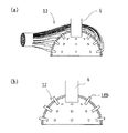
【0010】
更に、対物レンズ6の周囲には、対物レンズ6の光軸を中心としてドーム照明装置12が取り付けられている。このドーム照明装置12は、図2(a)に示すように、例えば多数の光ファイバー素線で構成された光ファイバーバンドルであって、互いに分離された各光ファイバー素線の先端部が半球状をなすよう配置されることにより形成されるか、或いは図2(b)に示すように、半球状の支持体に多数の光源例えばLEDを取り付けて、それらの発光端が試料面上の実質的に共通な一点に向かうように配置されることにより形成されたものである。そして、図2(a)に示された照明装置の場合、斜照明光源13からの照明光は、光ファイバー14によってドーム照明装置12まで導かれることにより、また、図2(b)に示された照明装置の場合には光源を一斉に点灯することにより、試料7の表面を落射照明では得られない照明角度(水平方向に近い角度までの広い角度)範囲で照明することが出来る。
【0011】
第1実施例は上記のように構成されているから、試料7が平坦或いは緩やかな傾斜面を持つ場合、落射照明光源1で照明された時の試料7からの反射光は対物レンズ6の開口内に戻り、一方、斜照明光源13で照明された時の試料7からの反射光は対物レンズ6の開口内には戻らない。従って、従来の共焦点顕微鏡と同様に良好なセクショニング画像が得られる。これに対して、図3(a)及び(b)に示すように試料7が球状或いは凹凸構造で急な斜面を持つ場合は、落射照明光源1で照明された時の試料7からの反射光は対物レンズ6の開口内に戻らないため、この部分のセクショニング画像が得られない。しかしながら、本実施例では斜照明光源13による照明を行っているため、斜照明光源13で照明された時の試料7からの反射光は対物レンズ6の開口内に戻る。この結果、落射照明光源1のみによる照明では得られなかった部分の像を得ることができる。
【0012】
なお、この斜照明光源13で得られる画像は、照明光が回転ディスク4のピンホールを通過していない。そのため、従来の共焦点顕微鏡で得られる画像に比べると、光軸に垂直な面内における分解能は低くなる。しかしながら、試料7からの反射光はピンホールを通過するので、セクショニング効果は失っていない。但し、本実施例におけるこの場合のセクショニング効果は、従来の共焦点顕微鏡のセクショニング効果と同じとは云えない。
【0013】
このように上記第1実施例によれば、従来の共焦点顕微鏡では観察不能であった部分の観察が簡単な構成で可能となる。しかも、何れの照明による像においても、程度の違いはあるもののセクショニング効果が損なわれることはない。
【0014】
図4は本発明に係る共焦点顕微鏡の第2実施例の構成図である。図中、従来技術及び上記第1実施例で示したのと実質上同一の部材には同一符号が付され、それらについての説明は省略されている。この実施例においては、回転ディスク15には例えば図5に示すようなピンホールパターンが形成されている。即ち、回転ディスク15の一方の半円部分にはマスクパターンとして複数のピンホールが形成されており、他方の半円部分にはマスクパターンが形成されておらず光は素通しとなる。また、回転ディスク15の周辺部には何れの半円部分が光路を通過しているかを識別するためのパターン15aが形成されている。回転ディスク15の周辺部には、このパターン15aと協働するように配置されたフォトセンサ16が設置されていて、回転ディスク15の回転動作に同期した信号(図6(a)参照)が生成されるようになっている。
【0015】
フォトセンサ16の出力端は落射照明光源1の電源回路と反転器17を介して斜照明光源13の電源回路にそれぞれ接続されていて、フォトセンサ16は、マスクパターンとしての複数のピンホールが形成されている半円部分が光路を通過している期間のみ落射照明光源1に対してON信号(図6(b)参照)を出し、逆に斜照明光源13に対しては反転器17によりOFF信号(図6(c)参照)を出力するようになっている。また、マスクターンが形成されていない半円部分が光路を通過している期間は、逆に落射照明光源1に対してOFF信号を出し、斜照明光源13に対しては反転器17によりON信号を出力する。なお、回転ディスク15の回転数は、CCDカメラ9のフレームレートに対して半分の速度で回転するように設定されている。つまり、回転ディスク15の半回転毎に一枚の画像がえられるような設定になっている。
【0016】
第2実施例は上記のように構成されているから、第1実施例の場合と同様に、試料7が平坦或いは緩やかな傾斜面を持つ場合は、落射照明光源1で照明された時の試料7からの反射光は、対物レンズ6の開口内に戻る。一方、斜照明光源13で照明された時の試料7からの反射光は、対物レンズの開口内には戻らない。従って、従来の共焦点顕微鏡と同様に良好なセクショニング画像が得られる。これに対して、試料7が球状又は凹凸構造で急な斜面を持つ場合は、落射照明光源1で照明された時の試料7からの反射光は、対物レンズ6の開口内には戻らない。一方、斜照明光源13で照明された時の試料7からの反射光は、対物レンズ6の開口内に戻ることになる。
【0017】
但し、本第2実施例の場合、第1実施例とは以下の点で異なる。即ち、第1点は、照明光に加えて試料7からの反射光も回転ディスク15のピンホールを通過しないため、従来の共焦点顕微鏡で得られる画像に比べると、光軸に垂直な面内における分解能が低く、セクショニング効果も認められない画像になる。即ち、従来の光学顕微鏡(非共焦点型)の明視野像と同じ像になる。しかしながら、従来の共焦点顕微鏡では反射光が殆ど戻らないために、観察不能であった部分の観察が可能となる。更に、斜照明光源13で得られる画像は、回転ディスク15のマスクパターンの形成されていない半円が光路を通過する期間に撮像されたものであるため、第1実施例に比べて光量ロスの少ない明るい画像が得られる。
【0018】
第2点は、回転ディスク15に光が素通しになる透明領域を備えていることである。この場合、落射照明光源1からの光は、ピンホールが形成されているパターン領域と透明領域による二つの異なる照明を行う。そこで、例えば試料7が平坦な場合を考えると、パターン領域を通過した光も透明領域を通過した光も、何れも試料7で反射して対物レンズの開口内を通過する。この結果、セクショニング画像の方が明視野像に比べて暗くなる。
【0019】
ところで、三次元画像はセクショニング画像から得られる。即ち、試料7と対物レンズ6との間の距離を変えながらセクショニング画像を撮像し、各画素で最も明るい値を保持するという信号処理を行う。そこで、明視野像が得られる状態でこの処理を行うと、明視野像がセクショニング画像に比べて明るいため、セクショニング画像の方が常に明視野像に基づいて信号処理が行われる。しかしながら、明視野像は所謂スライス像ではないので、上記信号処理を行っても正確な三次元画像は得られない。そこで、本第2実施例では、光源のON/OFF制御を行って、セクショニング画像が得られる部分では明視野像が得られないようにしている。コンピュタ10で三次元画像を構築する際は、上記のようにして交互に得られる2種類の画像について各画素毎に輝度値を比較して、輝度の大きい方を採用することにより、正確な三次元画像が得られるようにしている。
【0020】
以上説明したように、第2実施例によれば、従来の共焦点顕微鏡では観察不可能であった部分の観察が可能となる。また、第1実施例に比べても、光量ロスの少ない明るい画像を得ることが出来る。なお、本第2実施例では、各照明光による悪影響を回避するために、回転ディスク15の回転に同期させて落射照明光源と斜照明光源とを制御しているが、このような制御を行わなくても同様な効果が得られる場合もある。また、回転ディスク15とCCDカメラ9のフレームレートの関係を固定値に設定しているが、CCDカメラ9に対して回転ディスク15の回転動作により生成される信号を与えて同期を取る方法、或いは回転ディスク15の回転制御を行って、CCDカメラ9のフレームレートに対して回転ディスク15の回転数を制御する方法により、より安定した画像を得る方法もある。
【0021】
図7は本発明に係る共焦点顕微鏡の第3実施例の構成図である。図中、従来技術及び既述の実施例で示したのと実質上同一の部材には同一符号が付され、それらについての説明は省略されている。この実施例においては、第2実施例と同様に落射照明光源1及び斜照明光源13に対してのON/OFF制御を行うが、この制御をコンピュータにより例えばI/Oポートを用いて行うようにしたものである。即ち、この実施例では、予め試料7の形状(高さや構造)が分かっている場合、セクショニング画像を得る高さ毎に、何れの光源(或いは両方の光源)によって照明すべきかを決定できるので、予めプログラミングしておき、コンピュータ10によって落射照明光源1と斜照明光源13を制御して、三次元画像を構築することが出来る。
【0022】
更に、一様にマスクパターンが形成された回転ディスク4の代わりに、回転ディスクの径方向に応じて異なるパターンを形成した回転ディスクを用い、モーター5ごと移動させることにより、光路内に異なるマスクパターンを配置できるように構成し、照明する光源に応じてマスクパターンを切り替えるようにしても良い。例えば、図8に示すように第1の領域には従来通りのピンホールを配置し、第2の領域にはマスクパターンのない回転ディスク4を用い、試料7の比較的平坦な部分に対しては落射照明光源1により照明し、回転ディスクの第1の領域を光路内に配置して、セクショニング効果のある画像を得るようにしている。試料7の斜面部分に対しては斜照明光源13により照明し、回転ディスク4の第2の領域を光路内に配置して、斜面部分の明るい画像を得ることが出来る。
【0023】
以上、三つの実施例について説明したが、本発明はこれに限定されるものではない。例えば、上記第1、第2および第3の実施例においては、何れもマスクパターン部材として複数のピンホールを形成した回転ディスクを用いているが、これに限らず、図9及び図10に示すように、直線状の透光部18aと遮光部18bを交互に配置したパターンを有する回転ディスク18を用いても良い。また、例えば液晶表示装置に、回転ディスクが回転しているのと同様にピンホールを回転表示させたり、所定の範囲で揺動表示させたりすることにより実現させても良い。また、斜照明装置としてドーム照明装置を用いているが、例えばリング照明を同心円状に複数配置しても同様の効果が得られる。
【0024】
なお、図1に示した第1実施例では、ドーム照明装置12による照明のために光源13が設けられているが、この光源13の代わりにハーフミラー3を透過して集光レンズ2´で集光された光を光源として用いても良い(図1鎖線図示)。共焦点顕微鏡用の光源は高輝度のものが用いられることが多いので、ハーフミラー3を透過した光でも十分照明光として利用することが出来る。また、落射照明と斜照明とで同じような明るさの像が得られるように、ハーフミラー3の透過率特性を設定しても良い。また、光源1と13の光出射側にシャッター19を夫々設けて、このシャッター19を切り換えることにより、第2及び第3実施例で述べたのと同様の効果を得るようにすることも出来る。この場合、シャッター19は光源1及び13の何れか一方に設けて操作するようにしても良い。
【0026】
【発明の効果】
上述のように本発明によれば、従来の共焦点顕微鏡では観察できなかった試料の斜面部分をも観察できるようになるため、より正確な三次元画像の構築が可能となると共に、種々のアプリケーションに適用可能な共焦点顕微鏡を提供することが出来る。
【図面の簡単な説明】
【図1】本発明に係る共焦点顕微鏡の第1実施例の構成図である。
【図2】(a)は第1実施例に用いられるドーム照明装置の一例の一部破断斜視図、(b)は他の例の一部破断斜視図である。
【図3】(a)は試料が球状の場合の(b)は試料が凹凸構造で急な斜面を持つ場合の第1実施例における反射光の様子を夫々示す説明図である。
【図4】本発明に係る共焦点顕微鏡の第2実施例の構成図である。
【図5】第2実施例に用いられる回転ディスクのピンホールパターンを示す平面図である。
【図6】(a)は第2実施例における回転ディスクの回転動作に同期したフォトセンサ出力の変化を示す線図、(b)は落射照明光源に対するON/OFF信号を示す線図、(c)は斜照明光源に対するON/OFF信号を示す線図である。
【図7】本発明に係る共焦点顕微鏡の第3実施例の構成図である。
【図8】第3実施例に用いられる回転ディスクのピンホールパターンを示す平面図である。
【図9】回転ディスクの他の実施例を示す平面図である。
【図10】回転ディスクの更に他の実施例を示す平面図である。
【図11】従来の共焦点顕微鏡の構成図である。
【図12】従来の共焦点顕微鏡における反射光の様子を示す説明図で、(a)は試料が球状の場合、(b)は試料が凹凸構造で急な斜面を持つ場合である。
【符号の説明】
1 落射照明光源
2 コリメータレンズ
2´,8 集光レンズ
3 ハーフミラー
4,15,18 回転ディスク(マスクパターン部材)
5 モーター
6 対物レンズ
7 試料
9 CCDカメラ
10 コンピュータ
11 モニタ
12 ドーム照明装置
13 斜照明光源
14 ファイバー
16 フォトセンサ
17 反転器
19 シャッター[0001]
BACKGROUND OF THE INVENTION
The present invention relates to a confocal microscope having a high sectioning effect.
[0002]
[Prior art]
In general, there are two well-known confocal microscopes, the disk scan type and the laser scan type. Among these, the disk scan type confocal microscope has a higher lateral resolution than the normal microscope. In addition, it has a great feature that it has a very high sectioning effect in the height direction (Z direction) of the sample. Therefore, it has an excellent feature that a three-dimensional image of a sample can be constructed by combining a disk scanning confocal microscope and an image processing technique.
[0003]
FIG. 11 shows a typical configuration example of a disk scanning confocal microscope. This disc scanning confocal microscope has two observation methods, visual observation and observation with an imaging device (CCD camera). Here, an example using a CCD camera is shown. As shown in the drawing, the illumination light emitted from the
[0004]
The reflected light from the
The
[0005]
[Problems to be solved by the invention]
By the way, in this disk scanning confocal microscope, the illumination light that has passed through the pinhole of the rotating disk 4 irradiates the
[0006]
In this case, by switching to an objective lens having a large numerical aperture, reflected light can be taken into the aperture of the objective lens to a certain extent. It is difficult to use for various samples due to limited or limited magnification.
[0007]
The present invention has been made in view of the above-described problems of the prior art, and the object of the present invention is to be able to observe even a steep slope portion of a sample and construct a more accurate three-dimensional image. To provide a focusing microscope.
[0008]
[Means for Solving the Problems]
In order to achieve the above object, a confocal microscope according to the present invention includes an epi-illumination light source, a mask pattern member in which a light transmission part and a light-shielding part are formed in a predetermined pattern, and light from the epi-illumination light source. A confocal microscope including a first illumination optical system that guides to a mask pattern member and an objective lens that irradiates a sample with light from the mask pattern member, wherein the first illumination optics is provided by a plurality of light emitting means. A second illumination optical system for obliquely illuminating the sample with an optical path different from the optical path of the system, wherein each of the plurality of light-emitting means is installed so as to be substantially directed to one point on the sample, and the mask The pattern member includes a pattern region in which the predetermined pattern is formed and a transmission region in which the predetermined pattern is not formed, and the pattern region passes through the optical path of the first illumination optical system. To turn on the epi-illumination light source only periods, the transmission region is equal to or to turn on the plurality of light emitting means only while passing through the optical path of the first illumination optical system.
According to the present invention, the confocal microscope includes a switching mechanism that switches between illumination from the first illumination optical system and illumination from the second illumination optical system .
Also, according to the present invention, the boundary line of the pattern region and the transmissive region is formed toward the periphery from the center of the mask pattern member.
According to the invention, the boundary line between the pattern region and the transmission region is formed concentrically with respect to the center of the mask pattern member.
According to the present invention, the pattern region is formed in a slit shape in which linear light transmitting portions and light shielding portions are alternately arranged .
Also, according to the present invention, the second illumination optical system of the light emitting means is a light-emitting element.
According to the invention, the second illumination optical system selectively causes at least a part of the light emitting elements to emit light.
According to the invention, the switching mechanism is a shutter provided on at least one of the first illumination optical system and the second illumination optical system.
According to the invention, the second illumination optical system illuminates from a direction inclined with respect to the optical axis of the objective lens.
[0009]
DETAILED DESCRIPTION OF THE INVENTION
Hereinafter, embodiments of the present invention will be described based on illustrated examples. FIG. 1 is a configuration diagram of a first embodiment of a confocal microscope according to the present invention. In the figure, members that are substantially the same as those shown in the prior art are given the same reference numerals, and descriptions thereof are omitted. In this embodiment, the illumination light emitted from the epi-
[0010]
Further, a
[0011]
Since the first embodiment is configured as described above, when the
[0012]
In the image obtained by the oblique
[0013]
As described above, according to the first embodiment, it is possible to observe a portion that cannot be observed with the conventional confocal microscope with a simple configuration. In addition, the sectioning effect is not impaired in any illumination image although there is a difference in degree.
[0014]
FIG. 4 is a configuration diagram of a second embodiment of the confocal microscope according to the present invention. In the figure, members substantially the same as those shown in the prior art and the first embodiment are given the same reference numerals, and descriptions thereof are omitted. In this embodiment, the
[0015]
The output end of the
[0016]
Since the second embodiment is configured as described above, as in the case of the first embodiment, when the
[0017]
However, the second embodiment differs from the first embodiment in the following points. That is, the first point is that, in addition to the illumination light, the reflected light from the
[0018]
The second point is that the
[0019]
By the way, a three-dimensional image is obtained from a sectioning image. That is, a signal processing is performed in which a sectioning image is captured while changing the distance between the
[0020]
As described above, according to the second embodiment, it is possible to observe a portion that cannot be observed with a conventional confocal microscope. In addition, a bright image with less light loss can be obtained as compared with the first embodiment. In the second embodiment, the epi-illumination light source and the oblique illumination light source are controlled in synchronism with the rotation of the
[0021]
FIG. 7 is a configuration diagram of a third embodiment of the confocal microscope according to the present invention. In the figure, members substantially the same as those shown in the prior art and the above-described embodiments are denoted by the same reference numerals, and descriptions thereof are omitted. In this embodiment, ON / OFF control is performed on the epi-
[0022]
Further, instead of the rotating disk 4 on which the mask pattern is uniformly formed, a rotating disk on which a different pattern is formed according to the radial direction of the rotating disk is used. The mask pattern may be switched according to the light source to be illuminated. For example, as shown in FIG. 8, a conventional pinhole is disposed in the first area, and a rotating disk 4 without a mask pattern is used in the second area, and a relatively flat portion of the
[0023]
Although the three embodiments have been described above, the present invention is not limited to this. For example, in the first, second, and third embodiments, a rotating disk having a plurality of pinholes is used as the mask pattern member. However, the present invention is not limited to this, and is shown in FIGS. As described above, a
[0024]
In the first embodiment shown in FIG. 1, a
[0026]
【The invention's effect】
As described above, according to the present invention, it becomes possible to observe a slope portion of a sample that could not be observed with a conventional confocal microscope, so that it is possible to construct a more accurate three-dimensional image and various applications. A confocal microscope applicable to the above can be provided.
[Brief description of the drawings]
FIG. 1 is a configuration diagram of a first embodiment of a confocal microscope according to the present invention.
FIG. 2A is a partially broken perspective view of an example of a dome lighting device used in the first embodiment, and FIG. 2B is a partially broken perspective view of another example.
FIGS. 3A and 3B are explanatory views showing the state of reflected light in the first embodiment when the sample is spherical, and FIG. 3B is a diagram showing the reflected light in the first embodiment when the sample has an uneven structure and a steep slope.
FIG. 4 is a configuration diagram of a second embodiment of a confocal microscope according to the present invention.
FIG. 5 is a plan view showing a pinhole pattern of a rotating disk used in the second embodiment.
6A is a diagram showing changes in the photosensor output in synchronization with the rotating operation of the rotating disk in the second embodiment, FIG. 6B is a diagram showing ON / OFF signals for the epi-illumination light source, and FIG. ) Is a diagram showing an ON / OFF signal for an oblique illumination light source.
FIG. 7 is a configuration diagram of a third embodiment of a confocal microscope according to the present invention.
FIG. 8 is a plan view showing a pinhole pattern of a rotating disk used in the third embodiment.
FIG. 9 is a plan view showing another embodiment of the rotating disk.
FIG. 10 is a plan view showing still another embodiment of the rotating disk.
FIG. 11 is a configuration diagram of a conventional confocal microscope.
FIGS. 12A and 12B are explanatory diagrams showing the state of reflected light in a conventional confocal microscope, in which FIG. 12A shows a case where the sample is spherical, and FIG.
[Explanation of symbols]
DESCRIPTION OF
5
Claims (9)
Priority Applications (2)
| Application Number | Priority Date | Filing Date | Title |
|---|---|---|---|
| JP2002165124A JP4339553B2 (en) | 2001-06-26 | 2002-06-06 | Confocal microscope |
| PCT/JP2002/006273 WO2003010585A1 (en) | 2001-06-26 | 2002-06-24 | Confocal microscope |
Applications Claiming Priority (3)
| Application Number | Priority Date | Filing Date | Title |
|---|---|---|---|
| JP2001193289 | 2001-06-26 | ||
| JP2001-193289 | 2001-06-26 | ||
| JP2002165124A JP4339553B2 (en) | 2001-06-26 | 2002-06-06 | Confocal microscope |
Publications (3)
| Publication Number | Publication Date |
|---|---|
| JP2003084207A JP2003084207A (en) | 2003-03-19 |
| JP2003084207A5 JP2003084207A5 (en) | 2005-10-06 |
| JP4339553B2 true JP4339553B2 (en) | 2009-10-07 |
Family
ID=26617578
Family Applications (1)
| Application Number | Title | Priority Date | Filing Date |
|---|---|---|---|
| JP2002165124A Expired - Fee Related JP4339553B2 (en) | 2001-06-26 | 2002-06-06 | Confocal microscope |
Country Status (2)
| Country | Link |
|---|---|
| JP (1) | JP4339553B2 (en) |
| WO (1) | WO2003010585A1 (en) |
Families Citing this family (4)
| Publication number | Priority date | Publication date | Assignee | Title |
|---|---|---|---|---|
| DE10303825A1 (en) * | 2003-01-31 | 2004-08-12 | Leica Microsystems (Schweiz) Ag | Microscope with illumination |
| JP5095935B2 (en) * | 2005-11-15 | 2012-12-12 | オリンパス株式会社 | Microscope equipment |
| KR100788161B1 (en) * | 2006-01-06 | 2007-12-21 | (주)아모레퍼시픽 | A composition for skin whitening containing benzimidazole amine derivates or aminoquinoline derivatives |
| JP4677367B2 (en) * | 2006-06-05 | 2011-04-27 | オリンパス株式会社 | Illumination device and microscope system |
Family Cites Families (5)
| Publication number | Priority date | Publication date | Assignee | Title |
|---|---|---|---|---|
| JPH05113408A (en) * | 1991-10-22 | 1993-05-07 | Sony Corp | Reflection optical microscope with oblique illumination |
| US5932871A (en) * | 1995-11-08 | 1999-08-03 | Olympus Optical Co., Ltd. | Microscope having a confocal point and a non-confocal point, and a confocal point detect method applied thereto |
| JPH10170829A (en) * | 1996-12-12 | 1998-06-26 | Bunshi Bio Photonics Kenkyusho:Kk | Optical microscope |
| JP3533654B2 (en) * | 1997-01-23 | 2004-05-31 | 横河電機株式会社 | Confocal microscope |
| US6297904B1 (en) * | 1998-09-22 | 2001-10-02 | Olympus Optical Co., Ltd. | Inverted confocal microscope |
-
2002
- 2002-06-06 JP JP2002165124A patent/JP4339553B2/en not_active Expired - Fee Related
- 2002-06-24 WO PCT/JP2002/006273 patent/WO2003010585A1/en active Search and Examination
Also Published As
| Publication number | Publication date |
|---|---|
| WO2003010585A1 (en) | 2003-02-06 |
| JP2003084207A (en) | 2003-03-19 |
Similar Documents
| Publication | Publication Date | Title |
|---|---|---|
| US6687052B1 (en) | Confocal microscopy apparatus and method | |
| US6778323B2 (en) | Confocal microscope | |
| JP4825426B2 (en) | Dark field illuminator for biological microscopes | |
| US9383562B2 (en) | Optical arrangement | |
| JPS61120110A (en) | Lighting apparatus for bright and dark field microscope | |
| US20030063376A1 (en) | Microscope system | |
| US20110001818A1 (en) | Three dimensional shape measurement apparatus | |
| JPH10206740A (en) | Confocal equipment | |
| KR20020013861A (en) | Pattern forming member applied to sectioning image observing device and sectioning image observing device using it | |
| WO1988007695A1 (en) | Scanning confocal optical microscope | |
| RU2540453C2 (en) | Microscope, imaging device and imaging system | |
| JP2009282112A (en) | Confocal microscope | |
| JP2007033381A (en) | Optical inspection apparatus and its lighting method | |
| JP6226577B2 (en) | Confocal laser scanning microscope | |
| JP4339553B2 (en) | Confocal microscope | |
| JP2003043363A (en) | Confocal microscope | |
| JP4579554B2 (en) | Microscope illumination system | |
| JP4898588B2 (en) | Scanning microscope | |
| JP2001166219A (en) | Skin observation device | |
| JP2000275534A (en) | Confocal microscope | |
| JPH1195113A (en) | Confocal microscope and rotating disk applied to same | |
| JPH10288741A (en) | Microscope | |
| JP4268397B2 (en) | Magnifying observation device | |
| JP2004054108A (en) | Optical path splitting element and microscope using same | |
| JP3115100U (en) | microscope |
Legal Events
| Date | Code | Title | Description |
|---|---|---|---|
| A521 | Written amendment |
Free format text: JAPANESE INTERMEDIATE CODE: A523 Effective date: 20050516 |
|
| A621 | Written request for application examination |
Free format text: JAPANESE INTERMEDIATE CODE: A621 Effective date: 20050516 |
|
| A131 | Notification of reasons for refusal |
Free format text: JAPANESE INTERMEDIATE CODE: A131 Effective date: 20080617 |
|
| A521 | Written amendment |
Free format text: JAPANESE INTERMEDIATE CODE: A523 Effective date: 20080808 |
|
| TRDD | Decision of grant or rejection written | ||
| A01 | Written decision to grant a patent or to grant a registration (utility model) |
Free format text: JAPANESE INTERMEDIATE CODE: A01 Effective date: 20090609 |
|
| A01 | Written decision to grant a patent or to grant a registration (utility model) |
Free format text: JAPANESE INTERMEDIATE CODE: A01 |
|
| A61 | First payment of annual fees (during grant procedure) |
Free format text: JAPANESE INTERMEDIATE CODE: A61 Effective date: 20090702 |
|
| FPAY | Renewal fee payment (event date is renewal date of database) |
Free format text: PAYMENT UNTIL: 20120710 Year of fee payment: 3 |
|
| LAPS | Cancellation because of no payment of annual fees |