JP4339066B2 - Desiccant air conditioner - Google Patents
Desiccant air conditioner Download PDFInfo
- Publication number
- JP4339066B2 JP4339066B2 JP2003349038A JP2003349038A JP4339066B2 JP 4339066 B2 JP4339066 B2 JP 4339066B2 JP 2003349038 A JP2003349038 A JP 2003349038A JP 2003349038 A JP2003349038 A JP 2003349038A JP 4339066 B2 JP4339066 B2 JP 4339066B2
- Authority
- JP
- Japan
- Prior art keywords
- rotor
- zone
- air
- heater
- heat exchange
- Prior art date
- Legal status (The legal status is an assumption and is not a legal conclusion. Google has not performed a legal analysis and makes no representation as to the accuracy of the status listed.)
- Expired - Fee Related
Links
Images

Classifications
-
- F—MECHANICAL ENGINEERING; LIGHTING; HEATING; WEAPONS; BLASTING
- F24—HEATING; RANGES; VENTILATING
- F24F—AIR-CONDITIONING; AIR-HUMIDIFICATION; VENTILATION; USE OF AIR CURRENTS FOR SCREENING
- F24F3/00—Air-conditioning systems in which conditioned primary air is supplied from one or more central stations to distributing units in the rooms or spaces where it may receive secondary treatment; Apparatus specially designed for such systems
- F24F3/12—Air-conditioning systems in which conditioned primary air is supplied from one or more central stations to distributing units in the rooms or spaces where it may receive secondary treatment; Apparatus specially designed for such systems characterised by the treatment of the air otherwise than by heating and cooling
- F24F3/14—Air-conditioning systems in which conditioned primary air is supplied from one or more central stations to distributing units in the rooms or spaces where it may receive secondary treatment; Apparatus specially designed for such systems characterised by the treatment of the air otherwise than by heating and cooling by humidification; by dehumidification
- F24F3/1411—Air-conditioning systems in which conditioned primary air is supplied from one or more central stations to distributing units in the rooms or spaces where it may receive secondary treatment; Apparatus specially designed for such systems characterised by the treatment of the air otherwise than by heating and cooling by humidification; by dehumidification by absorbing or adsorbing water, e.g. using an hygroscopic desiccant
- F24F3/1423—Air-conditioning systems in which conditioned primary air is supplied from one or more central stations to distributing units in the rooms or spaces where it may receive secondary treatment; Apparatus specially designed for such systems characterised by the treatment of the air otherwise than by heating and cooling by humidification; by dehumidification by absorbing or adsorbing water, e.g. using an hygroscopic desiccant with a moving bed of solid desiccants, e.g. a rotary wheel supporting solid desiccants
-
- F—MECHANICAL ENGINEERING; LIGHTING; HEATING; WEAPONS; BLASTING
- F24—HEATING; RANGES; VENTILATING
- F24F—AIR-CONDITIONING; AIR-HUMIDIFICATION; VENTILATION; USE OF AIR CURRENTS FOR SCREENING
- F24F2203/00—Devices or apparatus used for air treatment
- F24F2203/10—Rotary wheel
- F24F2203/1004—Bearings or driving means
-
- F—MECHANICAL ENGINEERING; LIGHTING; HEATING; WEAPONS; BLASTING
- F24—HEATING; RANGES; VENTILATING
- F24F—AIR-CONDITIONING; AIR-HUMIDIFICATION; VENTILATION; USE OF AIR CURRENTS FOR SCREENING
- F24F2203/00—Devices or apparatus used for air treatment
- F24F2203/10—Rotary wheel
- F24F2203/1028—Rotary wheel combined with a spraying device
-
- F—MECHANICAL ENGINEERING; LIGHTING; HEATING; WEAPONS; BLASTING
- F24—HEATING; RANGES; VENTILATING
- F24F—AIR-CONDITIONING; AIR-HUMIDIFICATION; VENTILATION; USE OF AIR CURRENTS FOR SCREENING
- F24F2203/00—Devices or apparatus used for air treatment
- F24F2203/10—Rotary wheel
- F24F2203/1032—Desiccant wheel
-
- F—MECHANICAL ENGINEERING; LIGHTING; HEATING; WEAPONS; BLASTING
- F24—HEATING; RANGES; VENTILATING
- F24F—AIR-CONDITIONING; AIR-HUMIDIFICATION; VENTILATION; USE OF AIR CURRENTS FOR SCREENING
- F24F2203/00—Devices or apparatus used for air treatment
- F24F2203/10—Rotary wheel
- F24F2203/104—Heat exchanger wheel
-
- F—MECHANICAL ENGINEERING; LIGHTING; HEATING; WEAPONS; BLASTING
- F24—HEATING; RANGES; VENTILATING
- F24F—AIR-CONDITIONING; AIR-HUMIDIFICATION; VENTILATION; USE OF AIR CURRENTS FOR SCREENING
- F24F2203/00—Devices or apparatus used for air treatment
- F24F2203/10—Rotary wheel
- F24F2203/1056—Rotary wheel comprising a reheater
-
- F—MECHANICAL ENGINEERING; LIGHTING; HEATING; WEAPONS; BLASTING
- F24—HEATING; RANGES; VENTILATING
- F24F—AIR-CONDITIONING; AIR-HUMIDIFICATION; VENTILATION; USE OF AIR CURRENTS FOR SCREENING
- F24F2203/00—Devices or apparatus used for air treatment
- F24F2203/10—Rotary wheel
- F24F2203/1056—Rotary wheel comprising a reheater
- F24F2203/1064—Gas fired reheater
-
- F—MECHANICAL ENGINEERING; LIGHTING; HEATING; WEAPONS; BLASTING
- F24—HEATING; RANGES; VENTILATING
- F24F—AIR-CONDITIONING; AIR-HUMIDIFICATION; VENTILATION; USE OF AIR CURRENTS FOR SCREENING
- F24F2203/00—Devices or apparatus used for air treatment
- F24F2203/10—Rotary wheel
- F24F2203/1072—Rotary wheel comprising two rotors
-
- F—MECHANICAL ENGINEERING; LIGHTING; HEATING; WEAPONS; BLASTING
- F24—HEATING; RANGES; VENTILATING
- F24F—AIR-CONDITIONING; AIR-HUMIDIFICATION; VENTILATION; USE OF AIR CURRENTS FOR SCREENING
- F24F2203/00—Devices or apparatus used for air treatment
- F24F2203/10—Rotary wheel
- F24F2203/1084—Rotary wheel comprising two flow rotor segments
-
- F—MECHANICAL ENGINEERING; LIGHTING; HEATING; WEAPONS; BLASTING
- F24—HEATING; RANGES; VENTILATING
- F24F—AIR-CONDITIONING; AIR-HUMIDIFICATION; VENTILATION; USE OF AIR CURRENTS FOR SCREENING
- F24F2203/00—Devices or apparatus used for air treatment
- F24F2203/10—Rotary wheel
- F24F2203/1088—Rotary wheel comprising three flow rotor segments
Landscapes
- Engineering & Computer Science (AREA)
- Chemical & Material Sciences (AREA)
- Combustion & Propulsion (AREA)
- Mechanical Engineering (AREA)
- General Engineering & Computer Science (AREA)
- Central Air Conditioning (AREA)
Description
本発明は、たとえばシリカゲルやゼオライトなどの吸湿剤を担持した除湿ロータを用いるデシカント空調機に関し、特にエネルギー効率を改善したものである。 The present invention relates to a desiccant air conditioner using a dehumidifying rotor carrying a hygroscopic agent such as silica gel or zeolite, and particularly improves energy efficiency.
デシカント空調機は除湿ロータなどを用いることによって、被調和空気の除湿を行うものであって、エネルギー源として排熱などを用いることができ、よって省エネルギー効果が高くなるとともに、湿度の低い空気を供給することができ、快適性が高いため急速に普及している。 The desiccant air conditioner dehumidifies the conditioned air by using a dehumidification rotor, etc., and can use exhaust heat as an energy source, thus increasing the energy saving effect and supplying low humidity air It can be used and is rapidly becoming popular due to its high comfort.
現在普及している一般的な従来のデシカント空調機について図4に沿って説明する。図4は従来のデシカント空調機の断面図である。図4において除湿ロータ1は、吸湿剤が担持されたハニカム(蜂の巣)状のものである。 A general conventional desiccant air conditioner that is now widely used will be described with reference to FIG. FIG. 4 is a cross-sectional view of a conventional desiccant air conditioner. In FIG. 4, the dehumidifying rotor 1 is in the form of a honeycomb (honeycomb) on which a hygroscopic agent is supported.
顕熱交換ロータ2は、例えばアルミニウム箔をハニカム状に形成したものである。除湿ロータ1は吸着ゾーン3と脱着ゾーン4とに分割され、顕熱交換ロータ2は吸熱ゾーン5と放熱ゾーン6とに分割されている。ヒータ7は、具体的には温水コイルや蒸気コイルあるいは電気ヒータなどである。
The sensible
供給ブロア8は、外気OAを除湿ロータ1の吸着ゾーン3及び顕熱交換ロータ2の吸熱ゾーン5を通して室内へ供給するものである。排気ブロア9は、室内からの還気RAを顕熱交換ロータ2の放熱ゾーン6、ヒータ7及び除湿ロータ1の脱着ゾーン4を通して大気へ放出するものである。
The
以上のような従来の一般的なデシカント空調機は、より低湿度の空気を除湿ロータ1の脱着ゾーン4に供給しようとすると、ヒータ7へ供給する熱エネルギーを増やす必要がある。この際、ヒータ7が発電機などの排熱源から出る熱エネルギーを用いるものである場合、こうした熱エネルギーは限られており、場合によってはガスや灯油などを燃焼させるバーナーを併用して熱エネルギーを補充する必要があり、熱効率が低下する。
The conventional general desiccant air conditioner as described above needs to increase the heat energy supplied to the
このような点に着目して、より熱効率の高いデシカント空調機が近年提案されており、例えば特許文献1に開示されたものがある。
前記特許文献1に開示されたデシカント空調機は、除湿ロータの脱着ゾーンを2つに分割し、除湿ロータの回転方向に対して後方側部位の温度を前方側部位の温度より低くすることによって脱着に要するエネルギーを少なくし、熱効率を高くしたものである。 In the desiccant air conditioner disclosed in Patent Document 1, the desorption zone of the dehumidification rotor is divided into two, and the temperature of the rear part is made lower than the temperature of the front part with respect to the rotation direction of the dehumidification rotor. Energy required to increase heat efficiency.
しかし、脱着ゾーン前段側のヒータは除湿ロータの脱着に必要な温度が確保できることが前提であり、ヒータが排熱を利用するものである場合、必ずしも脱着に十分な温度が確保できるとは限らない。そしてそのような場合には特許文献1に記載のものは十分な性能を発揮できないという問題がある。 However, the heater on the upstream side of the desorption zone is based on the premise that the temperature necessary for desorption of the dehumidifying rotor can be secured, and when the heater uses exhaust heat, it is not always possible to ensure a sufficient temperature for desorption. . And in such a case, there exists a problem that the thing of patent document 1 cannot exhibit sufficient performance.
また排熱を利用する場合に脱着に十分な温度が確保できない場合は、補助ヒータを設けるとよいのであるが、特許文献1にはどのようにして補助ヒータを設けると合理的であるかの記載がない。 In addition, when exhaust heat is used and a temperature sufficient for desorption cannot be secured, an auxiliary heater may be provided. However, Patent Document 1 describes how it is reasonable to provide an auxiliary heater. There is no.
本発明は、前記課題を解消するためになされたもので、排熱を利用するヒータで脱着に十分な温度が確保できない場合に、できるたけ少ない消費エネルギーの補助ヒータを設けることが可能で、それによって総合的な熱効率の高いデシカント空調機を提供しようとするものである。 The present invention has been made to solve the above-mentioned problems, and when a heater that uses exhaust heat cannot secure a sufficient temperature for desorption, it is possible to provide an auxiliary heater that consumes as little energy as possible. It aims to provide a desiccant air conditioner with high overall thermal efficiency.
本発明に係るデシカント空調機は、除湿ロータと顕熱交換ロータの回転方向を互いに逆にするとともに、脱着ゾーンの除湿ロータ回転方向前方側部位に対向させてヒータとバーナーを設け、且つ脱着空気の流れに対して上流に前記ヒータ、下流に前記バーナーを配置するようにしたものである。 The desiccant air conditioner according to the present invention reverses the rotation directions of the dehumidification rotor and the sensible heat exchange rotor, and is provided with a heater and a burner so as to face the front side of the dehumidification rotor rotation direction of the desorption zone. The heater is arranged upstream with respect to the flow, and the burner is arranged downstream.
本発明のデシカント空調機は上記の如く構成したので、除湿ロータと顕熱交換ロータとの回転方向を逆にして、除湿ロータの低い温度でも脱着可能な部分、つまり脱着ゾーンに入ってすぐの除湿ロータに多くの湿気が含まれている部分に、顕熱交換ロータから出る最も高い温度の空気を導入して脱着が行える一方、これより除湿ロータ回転方向前方側の湿気が少なくなって脱着に高い温度が必要な部分に対しては、ヒータとバーナーを設け、顕熱交換ロータを通った空気をさらにヒータで加熱し、温度を高めた空気を通すようにしているため、除湿ロータの湿気の少なくなった部分でも脱着を進められる。 Since the desiccant air conditioner of the present invention is configured as described above, the rotational direction of the dehumidification rotor and the sensible heat exchange rotor is reversed so that the dehumidification rotor can be desorbed even at a low temperature, that is, immediately after entering the desorption zone. Desorption can be performed by introducing the highest temperature air from the sensible heat exchange rotor to the part where the rotor contains a lot of moisture, but the humidity on the front side in the dehumidifying rotor rotation direction is less and the desorption is high. For parts that require temperature, a heater and a burner are provided, and the air that has passed through the sensible heat exchange rotor is further heated by the heater so that the air at a higher temperature is passed through. Desorption can be promoted even in the part that became.
ヒータの温度が低すぎて十分に除湿ロータの脱着ができない場合は、空気をバーナーでさらに加熱することによって除湿ロータの脱着を十分に行うことができる。この場合にヒータによって既に空気の温度が上昇しているため、バーナーでの加熱エネルギーはそれほど大きくする必要がなく、よって全体として少ないエネルギーで動作をさせることができる。 When the temperature of the heater is too low to sufficiently desorb the dehumidifying rotor, the dehumidifying rotor can be sufficiently desorbed by further heating the air with a burner. In this case, since the temperature of the air is already increased by the heater, it is not necessary to increase the heating energy in the burner so much that the operation can be performed with a small amount of energy as a whole.
例えばヒータに燃料電池から排出される温水を流して、その排熱を利用するような場合には、燃料電池から出る温水の温度が摂氏60〜70度程度であるため、バーナーによって少し補助加熱をすることでデシカント空調機としての性能を十分に発揮することができる。 For example, when warm water discharged from the fuel cell is passed through the heater and the exhaust heat is used, the temperature of the warm water from the fuel cell is about 60 to 70 degrees Celsius. By doing so, the performance as a desiccant air conditioner can be fully exhibited.
またディーゼル発電機の冷却液の温度は摂氏70〜80度程度であり、この場合は外気の湿度が極めて高い場合にだけバーナーで補助加熱をすることによってデシカント空調機としての性能を発揮することができる。 Moreover, the temperature of the coolant of the diesel generator is about 70 to 80 degrees Celsius, and in this case, the performance as a desiccant air conditioner can be exhibited by performing auxiliary heating with a burner only when the humidity of the outside air is extremely high. it can.
そして供給空気の温度を下げるために加湿冷却器を用いる場合、加湿冷却器によって冷却した空気を放熱ゾーンの顕熱交換ロータ回転方向前方側部位に通すようにしているため、ヒータで加熱される空気を前もって冷却することがなく、加湿冷却器を用いることによってヒータの加熱効率を下げることがない。 When a humidifier cooler is used to lower the temperature of the supply air, the air cooled by the humidifier cooler is passed through the front side of the heat dissipation zone in the sensible heat exchange rotor rotation direction. Is not cooled in advance, and the heating efficiency of the heater is not lowered by using a humidified cooler.
このように多くの排熱源からの排熱を利用することができ、条件の悪い時でも性能の発揮できるデシカント空調機を提供することができる。従ってこれによって排熱の利用範囲が広がり、省エネルギーに貢献することができる。 As described above, it is possible to provide a desiccant air conditioner that can utilize exhaust heat from many exhaust heat sources and can exhibit performance even in poor conditions. Therefore, the range of utilization of exhaust heat is thereby widened, which can contribute to energy saving.
本発明のデシカント空調機は、除湿ロータと顕熱交換ロータの回転方向を互いに逆向きにするとともに、脱着ゾーンの除湿ロータ回転方向における前方側部位に対向させてヒータとバーナーを設け、そのヒータとバーナーとの位置関係は脱着空気の流れに対して上流にヒータ、下流にバーナーを配置するようにした。 The desiccant air conditioner of the present invention has a dehumidification rotor and a sensible heat exchange rotor that are rotated in opposite directions, and is provided with a heater and a burner so as to face a front side portion in the dehumidification rotor rotation direction of the desorption zone. Regarding the positional relationship with the burner, a heater was arranged upstream and a burner was arranged downstream of the flow of desorption air.
以下、本発明のデシカント空調機の実施例について図1〜図3に沿って詳細に説明する。ここで図4の従来のものと同一の構成部材については同一の番号を付与して、重複した説明を省略する。 Hereinafter, the Example of the desiccant air conditioner of this invention is described in detail along FIGS. 1-3. Here, the same constituent members as those of the conventional one shown in FIG.
つまり除湿ロータ1、顕熱交換ロータ2、吸着ゾーン3、脱着ゾーン4、吸熱ゾーン5と放熱ゾーン6、供給ブロア8、排気ブロア9は従来のものと共通であり、重複した説明は省略する。ヒータ7は発電機などの排熱源から供給される温水等の熱媒体によって空気を加熱するもの、例えば熱交換器などである。
That is, the dehumidification rotor 1, the sensible
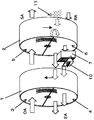
図1は本発明のデシカント空調機の内部を示す斜視図であり、これは供給ブロア8及び排気ブロア9の図示を省略している。バーナー10は、ヒータ7に隣接して設けられている。
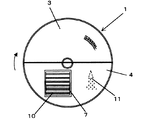
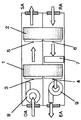
そして図1及び図2に示すように、脱着ゾーン4の除湿ロータ1回転方向における前方側部位に対向させてヒータ7とバーナー10を設け、そのヒータ7とバーナー10との位置関係は脱着空気の流れに対して上流側にヒータ7、下流側にバーナー10としている。また、ここでバーナー10としては天然ガス(LNG)や液化石油ガス(LPG)などを燃料としたバーナーを用いることができる。これらの燃料は一般的に硫黄分の含有量が少なく、燃焼ガスが直接除湿ロータ1を通過しても問題はない。なお図3は本発明のデシカント空調機の内部を示す断面図である。
FIG. 1 is a perspective view showing the inside of a desiccant air conditioner according to the present invention, in which a
As shown in FIGS. 1 and 2, a
また、還気RAを冷却する加湿冷却器11が顕熱交換ロータ2の上流側に配設され、放熱ゾーン6の顕熱交換ロータ2回転方向前方側部位に対向させて配置される。加湿冷却器11とは具体的には例えば水噴霧スプレーである。水噴霧スプレー以外には、例えば短冊状の濾紙を多数並設し、これに水を滴下したもの等も用いることができる。
Further, a humidifying
次に、本発明のデシカント空調機の動作について説明する。外気OAは供給ブロア8によって除湿ロータ1の吸着ゾーン3を通過すると、外気OA中の湿気が除湿ロータ1によって吸着され、吸着熱によって温度が上昇し、高温乾燥空気となる。
Next, the operation of the desiccant air conditioner of the present invention will be described. When the outside air OA passes through the
この高温乾燥空気は顕熱交換ロータ2の吸熱ゾーン5を通過することによって冷却され、快適な供給空気SAとなって室内へ供給される。ただし、乾燥空気の一部は顕熱交換ロータ2の回転に伴って図1及び図2の破線矢印で示すように還気RA側に戻る。
The high-temperature dry air is cooled by passing through the
一方、室内からの還気RAは低温乾燥状態であり、顕熱交換ロータ2の放熱ゾーン6を通過することによって顕熱交換ロータ2を冷却するとともに還気RAの温度が上昇する。ここで、放熱ゾーン6の顕熱交換ロータ2回転方向前方側部位に到達する還気RAは、加湿冷却器11を通過していることによって温度が下がっており、顕熱交換ロータ2の温度もさらに下がる。この温度の下がった顕熱交換ロータ2が吸熱ゾーン3に移動すると、ここを通過する乾燥空気の温度を大きく下げることができる。
On the other hand, the return air RA from the room is in a low-temperature dry state, and as the sensible
加湿冷却器11は放熱ゾーン6の顕熱交換ロータ2回転方向前方側部位の上流側に設けられており、この加湿冷却器11が存在しない放熱ゾーン6の顕熱交換ロータ2回転方向後方側部位を通過した空気の温度は前記顕熱交換ロータ2回転方向前方側部位を通過した空気の温度より高い。ヒータ7はこの温度の高い方の空気を加熱するため、還気を冷却する手段を設けてもヒータ7に入る空気の温度が下がることはなく、ヒータ7の加熱効果は損なわれない。
The
放熱ゾーン6を通って温度の上昇した還気RAは、その一部が直接除湿ロータ1に達し、残りはヒータ7及びバーナー10に達する。ヒータ7及びバーナー10に達する還気RAは、放熱ゾーン6の顕熱交換ロータ2回転方向後方側部位を通ったものである。つまり、吸熱ゾーン5から放熱ゾーン6に移行した直後の乾燥空気を一部取込んだ状態にある前記顕熱交換ロータ2回転方向後方側部位を経て、乾燥空気の混入した還気RAがヒータ7及びバーナー10を通過することとなる。
A part of the return air RA whose temperature has risen through the
よってバーナー10でLNGやLPGを燃焼させて水分が発生してもバーナー10を通過した高温空気の相対湿度はあまり上昇せず、除湿ロータ1の脱着に寄与することができる。
Therefore, even when LNG or LPG is burned by the
また、顕熱交換ロータ2における放熱ゾーン6の顕熱交換ロータ2回転方向前方側部位を通過する空気の温度は、放熱ゾーン6の顕熱交換ロータ2回転方向後方側部位を通過する空気の温度より低いが、この放熱ゾーン6の顕熱交換ロータ2回転方向前方側部位と対向する除湿ロータ1の脱着ゾーン4における除湿ロータ1回転方向後方側部位では保有湿気が多く、直接除湿ロータ1に達した低い温度の脱着空気でも十分に脱着が進む。
The temperature of the air passing through the sensible
ただし、脱着ゾーン4では除湿ロータ1回転方向前方側に向うほど保有湿気が少なくなり、より高い温度で脱着する必要がある。放熱ゾーン6の顕熱交換ロータ2回転方向後方側部位を通過して脱着ゾーン4に向う空気は、ヒータ7で加熱されて温度を高められた上で脱着に供される。
However, in the
ここで、ヒータ7に供給される熱源として温度の低い排熱媒体、例えばディーゼル発電機の冷却水や燃料電池から排出される温水などを用いると、場合によっては十分な温度まで脱着空気の温度を上げることができない。こういった場合には、ヒータ7の下流側に設けたバーナー10に点火して高温の燃焼ガスを発生させ、このバーナー10周辺を通過して温度を上昇させた空気を脱着ゾーン4に通すと、残った湿気を十分に脱着させることができる。
Here, when a low-temperature exhaust heat medium such as diesel generator cooling water or hot water discharged from a fuel cell is used as a heat source supplied to the
本発明のデシカント空調機は、例えば発電機などの排熱つまり温水を利用して除湿空調を行うことができると共に、排熱の温度が低い場合でもわずかなエネルギーを補うことによって高い性能を発揮でき、極めて高い省エネルギー効果を得ることができる。 The desiccant air conditioner of the present invention can perform dehumidification air conditioning using exhaust heat, that is, hot water of a generator, for example, and can exhibit high performance by supplementing slight energy even when the temperature of exhaust heat is low. An extremely high energy saving effect can be obtained.
1 除湿ロータ
2 顕熱交換ロータ
3 吸着ゾーン
4 脱着ゾーン
5 吸熱ゾーン
6 放熱ゾーン
7 ヒータ
8 供給ブロア
9 排気ブロア
10 バーナー
OA 外気
RA 還気
SA 供給空気
DESCRIPTION OF SYMBOLS 1
Claims (3)
前記除湿ロータと顕熱交換ロータの回転軸方向端面を互いに対向させて配置し、且つ前記吸着ゾーンと吸熱ゾーン、及び前記脱着ゾーンと放熱ゾーンをそれぞれ対向状態とすると共に、除湿ロータと顕熱交換ロータの回転方向を互いに逆とし、
前記除湿ロータと顕熱交換ロータとの間に、前記脱着ゾーンにおける除湿ロータ回転方向前方側部位に対向する配置で空気加熱用のヒータを配設すると共に、当該ヒータと除湿ロータとの間で且つヒータの下流側に、所定の燃料を燃焼させて高温の燃焼ガスを発生させるバーナーを配設し、
前記顕熱交換ロータの放熱ゾーンにおける顕熱交換ロータ回転方向前方側部位の上流側に加湿冷却器を設け、
前記ヒータが、加湿冷却器が存在しない放熱ゾーンの顕熱交換ロータ回転方向後方側部位を通過した空気を加熱することを
特徴とするデシカント空調機。 A dehumidification rotor and a sensible heat exchanging rotor made of a rotating body capable of flowing air substantially parallel to the rotation axis direction with respect to the inside, wherein the air circulation portion of the dehumidification rotor includes a moisture adsorption zone for the flowing air; In the desiccant air conditioner in which the air circulation part of the sensible heat exchange rotor is divided into a heat absorption zone and a heat dissipation zone for the flowing air, while being divided into a desorption zone,
The dehumidification rotor and the sensible heat exchange rotor are arranged so that the end surfaces in the rotation axis direction are opposed to each other, and the adsorption zone and the heat absorption zone, and the desorption zone and the heat radiation zone are opposed to each other. The rotor rotation directions are opposite to each other,
Between the dehumidifying rotor and sensible heat exchange rotor, while disposed a heater for air heating in an arrangement opposite to the dehumidifying rotor rotation direction front side portion in the desorbing zone, between the dehumidification row data with the heater In addition, a burner is disposed on the downstream side of the heater to generate a high-temperature combustion gas by burning predetermined fuel ,
A humidifier cooler is provided on the upstream side of the sensible heat exchange rotor rotation direction front side portion in the heat dissipation zone of the sensible heat exchange rotor,
The desiccant air conditioner characterized in that the heater heats the air that has passed through the rear side in the rotational direction of the sensible heat exchange rotor in the heat dissipation zone where no humidifier cooler exists .
Priority Applications (1)
| Application Number | Priority Date | Filing Date | Title |
|---|---|---|---|
| JP2003349038A JP4339066B2 (en) | 2003-10-08 | 2003-10-08 | Desiccant air conditioner |
Applications Claiming Priority (1)
| Application Number | Priority Date | Filing Date | Title |
|---|---|---|---|
| JP2003349038A JP4339066B2 (en) | 2003-10-08 | 2003-10-08 | Desiccant air conditioner |
Publications (2)
| Publication Number | Publication Date |
|---|---|
| JP2005114242A JP2005114242A (en) | 2005-04-28 |
| JP4339066B2 true JP4339066B2 (en) | 2009-10-07 |
Family
ID=34541011
Family Applications (1)
| Application Number | Title | Priority Date | Filing Date |
|---|---|---|---|
| JP2003349038A Expired - Fee Related JP4339066B2 (en) | 2003-10-08 | 2003-10-08 | Desiccant air conditioner |
Country Status (1)
| Country | Link |
|---|---|
| JP (1) | JP4339066B2 (en) |
-
2003
- 2003-10-08 JP JP2003349038A patent/JP4339066B2/en not_active Expired - Fee Related
Also Published As
| Publication number | Publication date |
|---|---|
| JP2005114242A (en) | 2005-04-28 |
Similar Documents
| Publication | Publication Date | Title |
|---|---|---|
| JP4340756B2 (en) | Dehumidifying air conditioner | |
| WO2025189857A1 (en) | Flue gas low-temperature purification system | |
| US10274210B2 (en) | Heat pump humidifier and dehumidifier system and method | |
| JP4122346B2 (en) | Dehumidifying air conditioner | |
| JP2002054838A (en) | Dehumidifying air conditioner | |
| JP4749559B2 (en) | Dehumidifying air conditioner | |
| JP2005114242A (en) | Desiccant air conditioner | |
| JPH0942709A (en) | Desiccant air conditioner | |
| JP4414110B2 (en) | Dehumidifying air conditioner | |
| JP2005049035A (en) | Desiccant air conditioner | |
| JP2000283497A (en) | Adsorption dehumidifying air conditioner | |
| JP4348531B2 (en) | Dehumidifying air conditioner | |
| JP3933494B2 (en) | Desiccant dehumidification method and desiccant dehumidifier | |
| JP2011094904A (en) | Desiccant type ventilation fan | |
| JP4436900B2 (en) | Desiccant air conditioner | |
| JP5822653B2 (en) | Desiccant air conditioner | |
| JP3336539B2 (en) | Dehumidifier and dehumidifying air conditioner using the same | |
| JP2004324907A (en) | Co-generation air conditioner | |
| JP2011141057A (en) | Desiccant type ventilation fan | |
| JP2002333161A (en) | Dehumidification air conditioning system | |
| JP3300780B1 (en) | Internal combustion engine cogeneration system | |
| JP5822652B2 (en) | Cogeneration system | |
| JP4698901B2 (en) | Dehumidifying air conditioner | |
| JP2007322032A (en) | Desiccant air conditioning system | |
| JP2003035414A (en) | Forced charge combustion device |
Legal Events
| Date | Code | Title | Description |
|---|---|---|---|
| A711 | Notification of change in applicant |
Free format text: JAPANESE INTERMEDIATE CODE: A711 Effective date: 20060403 |
|
| A521 | Request for written amendment filed |
Free format text: JAPANESE INTERMEDIATE CODE: A821 Effective date: 20060405 |
|
| A621 | Written request for application examination |
Free format text: JAPANESE INTERMEDIATE CODE: A621 Effective date: 20061004 |
|
| A977 | Report on retrieval |
Free format text: JAPANESE INTERMEDIATE CODE: A971007 Effective date: 20080919 |
|
| A131 | Notification of reasons for refusal |
Free format text: JAPANESE INTERMEDIATE CODE: A131 Effective date: 20080930 |
|
| A521 | Request for written amendment filed |
Free format text: JAPANESE INTERMEDIATE CODE: A523 Effective date: 20081201 |
|
| TRDD | Decision of grant or rejection written | ||
| A01 | Written decision to grant a patent or to grant a registration (utility model) |
Free format text: JAPANESE INTERMEDIATE CODE: A01 Effective date: 20090623 |
|
| A01 | Written decision to grant a patent or to grant a registration (utility model) |
Free format text: JAPANESE INTERMEDIATE CODE: A01 |
|
| A61 | First payment of annual fees (during grant procedure) |
Free format text: JAPANESE INTERMEDIATE CODE: A61 Effective date: 20090701 |
|
| R150 | Certificate of patent or registration of utility model |
Ref document number: 4339066 Country of ref document: JP Free format text: JAPANESE INTERMEDIATE CODE: R150 Free format text: JAPANESE INTERMEDIATE CODE: R150 |
|
| FPAY | Renewal fee payment (event date is renewal date of database) |
Free format text: PAYMENT UNTIL: 20120710 Year of fee payment: 3 |
|
| FPAY | Renewal fee payment (event date is renewal date of database) |
Free format text: PAYMENT UNTIL: 20120710 Year of fee payment: 3 |
|
| FPAY | Renewal fee payment (event date is renewal date of database) |
Free format text: PAYMENT UNTIL: 20120710 Year of fee payment: 3 |
|
| FPAY | Renewal fee payment (event date is renewal date of database) |
Free format text: PAYMENT UNTIL: 20130710 Year of fee payment: 4 |
|
| FPAY | Renewal fee payment (event date is renewal date of database) |
Free format text: PAYMENT UNTIL: 20130710 Year of fee payment: 4 |
|
| FPAY | Renewal fee payment (event date is renewal date of database) |
Free format text: PAYMENT UNTIL: 20130710 Year of fee payment: 4 |
|
| FPAY | Renewal fee payment (event date is renewal date of database) |
Free format text: PAYMENT UNTIL: 20130710 Year of fee payment: 4 |
|
| FPAY | Renewal fee payment (event date is renewal date of database) |
Free format text: PAYMENT UNTIL: 20130710 Year of fee payment: 4 |
|
| R250 | Receipt of annual fees |
Free format text: JAPANESE INTERMEDIATE CODE: R250 |
|
| R250 | Receipt of annual fees |
Free format text: JAPANESE INTERMEDIATE CODE: R250 |
|
| R250 | Receipt of annual fees |
Free format text: JAPANESE INTERMEDIATE CODE: R250 |
|
| R250 | Receipt of annual fees |
Free format text: JAPANESE INTERMEDIATE CODE: R250 |
|
| R250 | Receipt of annual fees |
Free format text: JAPANESE INTERMEDIATE CODE: R250 |
|
| R250 | Receipt of annual fees |
Free format text: JAPANESE INTERMEDIATE CODE: R250 |
|
| R250 | Receipt of annual fees |
Free format text: JAPANESE INTERMEDIATE CODE: R250 |
|
| R250 | Receipt of annual fees |
Free format text: JAPANESE INTERMEDIATE CODE: R250 |
|
| R250 | Receipt of annual fees |
Free format text: JAPANESE INTERMEDIATE CODE: R250 |
|
| R250 | Receipt of annual fees |
Free format text: JAPANESE INTERMEDIATE CODE: R250 |
|
| LAPS | Cancellation because of no payment of annual fees |