JP4339028B2 - Lamp unit and vehicle headlamp - Google Patents
Lamp unit and vehicle headlamp Download PDFInfo
- Publication number
- JP4339028B2 JP4339028B2 JP2003175213A JP2003175213A JP4339028B2 JP 4339028 B2 JP4339028 B2 JP 4339028B2 JP 2003175213 A JP2003175213 A JP 2003175213A JP 2003175213 A JP2003175213 A JP 2003175213A JP 4339028 B2 JP4339028 B2 JP 4339028B2
- Authority
- JP
- Japan
- Prior art keywords
- light
- translucent member
- light source
- lamp unit
- line
- Prior art date
- Legal status (The legal status is an assumption and is not a legal conclusion. Google has not performed a legal analysis and makes no representation as to the accuracy of the status listed.)
- Expired - Fee Related
Links
Images

Classifications
-
- F—MECHANICAL ENGINEERING; LIGHTING; HEATING; WEAPONS; BLASTING
- F21—LIGHTING
- F21V—FUNCTIONAL FEATURES OR DETAILS OF LIGHTING DEVICES OR SYSTEMS THEREOF; STRUCTURAL COMBINATIONS OF LIGHTING DEVICES WITH OTHER ARTICLES, NOT OTHERWISE PROVIDED FOR
- F21V7/00—Reflectors for light sources
- F21V7/0008—Reflectors for light sources providing for indirect lighting
- F21V7/0016—Reflectors for light sources providing for indirect lighting on lighting devices that also provide for direct lighting, e.g. by means of independent light sources, by splitting of the light beam, by switching between both lighting modes
-
- F—MECHANICAL ENGINEERING; LIGHTING; HEATING; WEAPONS; BLASTING
- F21—LIGHTING
- F21S—NON-PORTABLE LIGHTING DEVICES; SYSTEMS THEREOF; VEHICLE LIGHTING DEVICES SPECIALLY ADAPTED FOR VEHICLE EXTERIORS
- F21S41/00—Illuminating devices specially adapted for vehicle exteriors, e.g. headlamps
- F21S41/10—Illuminating devices specially adapted for vehicle exteriors, e.g. headlamps characterised by the light source
- F21S41/14—Illuminating devices specially adapted for vehicle exteriors, e.g. headlamps characterised by the light source characterised by the type of light source
- F21S41/141—Light emitting diodes [LED]
- F21S41/143—Light emitting diodes [LED] the main emission direction of the LED being parallel to the optical axis of the illuminating device
-
- F—MECHANICAL ENGINEERING; LIGHTING; HEATING; WEAPONS; BLASTING
- F21—LIGHTING
- F21S—NON-PORTABLE LIGHTING DEVICES; SYSTEMS THEREOF; VEHICLE LIGHTING DEVICES SPECIALLY ADAPTED FOR VEHICLE EXTERIORS
- F21S41/00—Illuminating devices specially adapted for vehicle exteriors, e.g. headlamps
- F21S41/10—Illuminating devices specially adapted for vehicle exteriors, e.g. headlamps characterised by the light source
- F21S41/14—Illuminating devices specially adapted for vehicle exteriors, e.g. headlamps characterised by the light source characterised by the type of light source
- F21S41/141—Light emitting diodes [LED]
- F21S41/151—Light emitting diodes [LED] arranged in one or more lines
- F21S41/153—Light emitting diodes [LED] arranged in one or more lines arranged in a matrix
-
- F—MECHANICAL ENGINEERING; LIGHTING; HEATING; WEAPONS; BLASTING
- F21—LIGHTING
- F21S—NON-PORTABLE LIGHTING DEVICES; SYSTEMS THEREOF; VEHICLE LIGHTING DEVICES SPECIALLY ADAPTED FOR VEHICLE EXTERIORS
- F21S41/00—Illuminating devices specially adapted for vehicle exteriors, e.g. headlamps
- F21S41/10—Illuminating devices specially adapted for vehicle exteriors, e.g. headlamps characterised by the light source
- F21S41/14—Illuminating devices specially adapted for vehicle exteriors, e.g. headlamps characterised by the light source characterised by the type of light source
- F21S41/141—Light emitting diodes [LED]
- F21S41/155—Surface emitters, e.g. organic light emitting diodes [OLED]
-
- F—MECHANICAL ENGINEERING; LIGHTING; HEATING; WEAPONS; BLASTING
- F21—LIGHTING
- F21S—NON-PORTABLE LIGHTING DEVICES; SYSTEMS THEREOF; VEHICLE LIGHTING DEVICES SPECIALLY ADAPTED FOR VEHICLE EXTERIORS
- F21S41/00—Illuminating devices specially adapted for vehicle exteriors, e.g. headlamps
- F21S41/20—Illuminating devices specially adapted for vehicle exteriors, e.g. headlamps characterised by refractors, transparent cover plates, light guides or filters
- F21S41/285—Refractors, transparent cover plates, light guides or filters not provided in groups F21S41/24 - F21S41/2805
-
- F—MECHANICAL ENGINEERING; LIGHTING; HEATING; WEAPONS; BLASTING
- F21—LIGHTING
- F21S—NON-PORTABLE LIGHTING DEVICES; SYSTEMS THEREOF; VEHICLE LIGHTING DEVICES SPECIALLY ADAPTED FOR VEHICLE EXTERIORS
- F21S41/00—Illuminating devices specially adapted for vehicle exteriors, e.g. headlamps
- F21S41/30—Illuminating devices specially adapted for vehicle exteriors, e.g. headlamps characterised by reflectors
- F21S41/32—Optical layout thereof
- F21S41/321—Optical layout thereof the reflector being a surface of revolution or a planar surface, e.g. truncated
-
- F—MECHANICAL ENGINEERING; LIGHTING; HEATING; WEAPONS; BLASTING
- F21—LIGHTING
- F21S—NON-PORTABLE LIGHTING DEVICES; SYSTEMS THEREOF; VEHICLE LIGHTING DEVICES SPECIALLY ADAPTED FOR VEHICLE EXTERIORS
- F21S41/00—Illuminating devices specially adapted for vehicle exteriors, e.g. headlamps
- F21S41/30—Illuminating devices specially adapted for vehicle exteriors, e.g. headlamps characterised by reflectors
- F21S41/32—Optical layout thereof
- F21S41/322—Optical layout thereof the reflector using total internal reflection
-
- F—MECHANICAL ENGINEERING; LIGHTING; HEATING; WEAPONS; BLASTING
- F21—LIGHTING
- F21S—NON-PORTABLE LIGHTING DEVICES; SYSTEMS THEREOF; VEHICLE LIGHTING DEVICES SPECIALLY ADAPTED FOR VEHICLE EXTERIORS
- F21S41/00—Illuminating devices specially adapted for vehicle exteriors, e.g. headlamps
- F21S41/30—Illuminating devices specially adapted for vehicle exteriors, e.g. headlamps characterised by reflectors
- F21S41/32—Optical layout thereof
- F21S41/33—Multi-surface reflectors, e.g. reflectors with facets or reflectors with portions of different curvature
- F21S41/334—Multi-surface reflectors, e.g. reflectors with facets or reflectors with portions of different curvature the reflector consisting of patch like sectors
- F21S41/336—Multi-surface reflectors, e.g. reflectors with facets or reflectors with portions of different curvature the reflector consisting of patch like sectors with discontinuity at the junction between adjacent areas
-
- F—MECHANICAL ENGINEERING; LIGHTING; HEATING; WEAPONS; BLASTING
- F21—LIGHTING
- F21S—NON-PORTABLE LIGHTING DEVICES; SYSTEMS THEREOF; VEHICLE LIGHTING DEVICES SPECIALLY ADAPTED FOR VEHICLE EXTERIORS
- F21S41/00—Illuminating devices specially adapted for vehicle exteriors, e.g. headlamps
- F21S41/30—Illuminating devices specially adapted for vehicle exteriors, e.g. headlamps characterised by reflectors
- F21S41/32—Optical layout thereof
- F21S41/36—Combinations of two or more separate reflectors
- F21S41/365—Combinations of two or more separate reflectors successively reflecting the light
-
- F—MECHANICAL ENGINEERING; LIGHTING; HEATING; WEAPONS; BLASTING
- F21—LIGHTING
- F21S—NON-PORTABLE LIGHTING DEVICES; SYSTEMS THEREOF; VEHICLE LIGHTING DEVICES SPECIALLY ADAPTED FOR VEHICLE EXTERIORS
- F21S41/00—Illuminating devices specially adapted for vehicle exteriors, e.g. headlamps
- F21S41/30—Illuminating devices specially adapted for vehicle exteriors, e.g. headlamps characterised by reflectors
- F21S41/37—Illuminating devices specially adapted for vehicle exteriors, e.g. headlamps characterised by reflectors characterised by their material, surface treatment or coatings
-
- F—MECHANICAL ENGINEERING; LIGHTING; HEATING; WEAPONS; BLASTING
- F21—LIGHTING
- F21V—FUNCTIONAL FEATURES OR DETAILS OF LIGHTING DEVICES OR SYSTEMS THEREOF; STRUCTURAL COMBINATIONS OF LIGHTING DEVICES WITH OTHER ARTICLES, NOT OTHERWISE PROVIDED FOR
- F21V13/00—Producing particular characteristics or distribution of the light emitted by means of a combination of elements specified in two or more of main groups F21V1/00 - F21V11/00
- F21V13/02—Combinations of only two kinds of elements
- F21V13/04—Combinations of only two kinds of elements the elements being reflectors and refractors
-
- F—MECHANICAL ENGINEERING; LIGHTING; HEATING; WEAPONS; BLASTING
- F21—LIGHTING
- F21V—FUNCTIONAL FEATURES OR DETAILS OF LIGHTING DEVICES OR SYSTEMS THEREOF; STRUCTURAL COMBINATIONS OF LIGHTING DEVICES WITH OTHER ARTICLES, NOT OTHERWISE PROVIDED FOR
- F21V31/00—Gas-tight or water-tight arrangements
- F21V31/04—Provision of filling media
-
- F—MECHANICAL ENGINEERING; LIGHTING; HEATING; WEAPONS; BLASTING
- F21—LIGHTING
- F21Y—INDEXING SCHEME ASSOCIATED WITH SUBCLASSES F21K, F21L, F21S and F21V, RELATING TO THE FORM OR THE KIND OF THE LIGHT SOURCES OR OF THE COLOUR OF THE LIGHT EMITTED
- F21Y2115/00—Light-generating elements of semiconductor light sources
- F21Y2115/10—Light-emitting diodes [LED]
-
- H—ELECTRICITY
- H10—SEMICONDUCTOR DEVICES; ELECTRIC SOLID-STATE DEVICES NOT OTHERWISE PROVIDED FOR
- H10H—INORGANIC LIGHT-EMITTING SEMICONDUCTOR DEVICES HAVING POTENTIAL BARRIERS
- H10H20/00—Individual inorganic light-emitting semiconductor devices having potential barriers, e.g. light-emitting diodes [LED]
- H10H20/80—Constructional details
- H10H20/85—Packages
-
- Y—GENERAL TAGGING OF NEW TECHNOLOGICAL DEVELOPMENTS; GENERAL TAGGING OF CROSS-SECTIONAL TECHNOLOGIES SPANNING OVER SEVERAL SECTIONS OF THE IPC; TECHNICAL SUBJECTS COVERED BY FORMER USPC CROSS-REFERENCE ART COLLECTIONS [XRACs] AND DIGESTS
- Y10—TECHNICAL SUBJECTS COVERED BY FORMER USPC
- Y10S—TECHNICAL SUBJECTS COVERED BY FORMER USPC CROSS-REFERENCE ART COLLECTIONS [XRACs] AND DIGESTS
- Y10S362/00—Illumination
- Y10S362/80—Light emitting diode
Landscapes
- Engineering & Computer Science (AREA)
- General Engineering & Computer Science (AREA)
- Physics & Mathematics (AREA)
- Microelectronics & Electronic Packaging (AREA)
- Optics & Photonics (AREA)
- Mathematical Physics (AREA)
- Non-Portable Lighting Devices Or Systems Thereof (AREA)
Description
【0001】
【発明の属する技術分野】
本願発明は、車両用前照灯においてカットオフラインの直線部分を形成するために用いられる灯具ユニット等に関するものである。
【0002】
【従来の技術】
従来より、例えば「特許文献1」に記載されているように、光源からの光をリフレクタで拡散反射制御することにより、上端部に所定のカットオフラインを有する配光パターンを形成するように構成された車両用前照灯が知られている。
【0003】
また「特許文献2」には、発光ダイオードの発光チップからの光を、その封止樹脂部材の前面で反射させた後に該封止樹脂部材の後面で反射させて該封止樹脂部材の前面から出射させるように構成された光学装置が記載されている。
【0004】
【特許文献1】
特開2001−351410号公報
【特許文献2】
特開2002−94129号公報
【発明が解決しようとする課題】
上記「特許文献2」に記載された光学装置を車両用前照灯の灯具ユニットとして用いるようにすれば、灯具ユニットを薄型に構成することが可能となる。
【0005】
しかしながら、上記「特許文献2」に記載された光学装置からの光照射によって形成される配光パターンは、その輪郭がかなり不鮮明なものとなってしまうので、この光学装置をカットオフライン形成用の灯具ユニットとして用いることはできない、という問題がある。
【0006】
本願発明は、このような事情に鑑みてなされたものであって、車両用前照灯においてカットオフラインの直線部分を形成するために用いられる灯具ユニットとして、薄型の構成で鮮明なカットオフラインを形成可能な灯具ユニット等を提供することを目的とするものである。
【0007】
【課題を解決するための手段】
本願発明は、光源として半導体発光素子を用いるとともに、この光源からの光が入射するように透光部材を配置した上で、その光源の配置および透光部材の構成に工夫を施すことにより、上記目的達成を図るようにしたものである。
【0008】
すなわち、本願発明に係る車両用前照灯は、
上端部に所定のカットオフラインを有する配光パターンを形成するように構成された車両用前照灯において、上記カットオフラインの直線部分を形成するために用いられる灯具ユニットであって、
一辺が直線状に延びる発光チップを有する半導体発光素子からなる光源と、この光源からの光を入射させるように配置された透光部材とを備えてなり、
上記光源が、上記発光チップの一辺を該発光チップの下端部に位置させた状態で該一辺を上記灯具ユニットの光軸と直交させるようにして前向きに配置されており、
上記透光部材が、上記光源からの入射光を該透光部材の前面で反射させた後に該透光部材の後面で反射させて該透光部材の前面から出射させるように構成されており、
上記透光部材の前面が、上記光軸と直交する平面で構成されるとともに、上記透光部材の後面が、該透光部材の前面に関して上記光源の発光中心と対称の位置を焦点とする回転放物面を基準面として形成された所定の光反射制御面で構成されており、
上記透光部材の前面における光軸近傍領域に鏡面処理が施されるとともに、上記透光部材の後面に鏡面処理が施されている、ことを特徴とするものである。
【0009】
上記「所定のカットオフライン」の具体的な形状は特に限定されるものではなく、例えば、水平方向に延びる水平カットオフラインとこの水平カットオフラインから斜め上方へ延びる斜めカットオフラインとからなる形状や、左右1対の水平カットオフラインが段違いで階段状に形成された形状等が採用可能である。
【0010】
上記「カットオフラインの直線部分」の具体的な位置は特に限定されるものではなく、例えば、水平方向に延びる直線部分や水平方向に対して所定角度で斜め方向に延びる直線部分等が採用可能である。
上記「半導体発光素子」の種類は特に限定されるものではなく、例えば、発光ダイオードやレーザダイオード等が採用可能である。
【0011】
上記「発光チップ」は、一辺が直線状に延びるように形成されたものであれば、その形状は特に限定されるものではなく、例えば、正方形、長方形、平行四辺形、六角形、半円形等が採用可能である。
【0012】
上記「回転放物面を基準面として形成された所定の光反射制御面」の具体的形状は特に限定されるものではなく、例えば、回転放物面自体で構成されたもの、回転放物面上に複数の反射素子が形成されたもの、回転放物面を変形させた曲面で構成されたもの等が採用可能である。
【0013】
上記「鏡面処理」は、鏡面反射を可能とするための処理を意味するものであって、アルミニウム蒸着等の表面処理によって鏡面処理を施すようにしてよいことはもちろんであるが、鏡面を有する部材を貼り付けること等によって鏡面処理を施すことも可能である。
【0014】
【発明の作用効果】
上記構成に示すように、本願発明に係る灯具ユニットは、一辺が直線状に延びる発光チップを有する半導体発光素子からなる光源と、この光源からの光を入射させるように配置された透光部材とを備えてなり、車両用前照灯においてカットオフラインの直線部分を形成するために用いられるようになっているが、その光源は、発光チップの一辺をその下端部に位置させた状態で該一辺を灯具ユニットの光軸と直交させるようにして前向きに配置されており、その透光部材は、光源からの入射光をその前面で反射させた後にその後面で反射させてその前面から出射させるように構成されており、その際、透光部材の前面は光軸と直交する平面で構成されるとともに、該透光部材の後面はその前面に関して光源の発光中心と対称の位置を焦点とする回転放物面を基準面として形成された所定の光反射制御面で構成されており、また、透光部材の前面における光軸近傍領域に鏡面処理が施されるとともに透光部材の後面に鏡面処理が施されているので、次のような作用効果を得ることができる。
【0015】
すなわち、光源から透光部材に入射した光の大半はその前面に到達するが、その際、比較的光軸寄りの方向へ向かう光は、鏡面処理が施された光軸近傍領域に入射するので、該光軸近傍領域で反射してその多くが透光部材の後面に入射する。一方、光源から透光部材に入射した光のうち光軸から大きく離れた方向へ向かう光は、透光部材の前面に対して大きな入射角で入射するので、その大半が前面で内面反射して透光部材の後面に入射する。その際、透光部材の前面は光軸と直交する平面で構成されているので、透光部材の後面への入射光は、透光部材の前面に関して発光チップと対称の位置を仮想光源とする発散光となるが、透光部材の後面は、仮想光源の位置を焦点とする回転放物面を基準面として形成された所定の光反射制御面で構成されているので、その後面で反射してその前面から出射する光の方向を精度良く制御することができる。
【0016】
また、本願発明に係る灯具ユニットの光源は、その発光チップの一辺を該発光チップの下端部に位置させた状態で光軸と直交させるようにして前向きに配置されているので、この灯具ユニットからの光照射により形成される配光パターンは、上記一辺の反転像により鮮明なカットオフラインを有するものとなる。
【0017】
しかも、本願発明に係る灯具ユニットは、その光源が半導体発光素子で構成されており、この光源から光を透光部材の内部で2回反射させて前方へ出射させるように構成されているので、灯具ユニットを薄型に構成することができる。
【0018】
このように本願発明によれば、車両用前照灯においてカットオフラインの直線部分を形成するために用いられる灯具ユニットとして、薄型の構成で鮮明なカットオフラインを形成可能な灯具ユニットを得ることができる。
【0019】
さらに、本願発明に係る灯具ユニットは、その透光部材の前面における光軸近傍領域に鏡面処理が施されているので、光源からの光が上向きの直射光として灯具ユニットの前方へ照射されてしまうのを未然に防止することができ、これにより対向車ドライバ等にグレアを与えてしまうのを効果的に抑制することができる。
【0020】
上記構成において、透光部材の後面を構成する光反射制御面を、該光反射制御面への入射光を発光チップの一辺と平行な方向に拡散偏向反射させるように構成すれば、カットオフラインに沿って長く延びる配光パターンを形成して鮮明なカットオフラインを安定的に形成したり、配光パターンのカットオフライン近傍における光度分布を所望する光度分布に設定することが容易に可能となる。
【0021】
ここで「発光チップの一辺と平行な方向に拡散偏向反射させる」とは、反射光を発光チップの一辺と平行な方向に拡散させること、反射光を発光チップの一辺と平行な方向に偏向させること、およびこれら拡散および偏向を同時に行うこと、のいずれかを意味するものである。
【0022】
上記構成において、透光部材の前面において鏡面処理が施された「光軸近傍領域」の大きさや形状は特に限定されるものではないが、この「光軸近傍領域」の外周縁の位置を、透光部材の前面に入射する光源から光の入射角が該透光部材の臨界角と略同じ値となる位置に設定するようにすれば、該光軸近傍領域の存在によって透光部材の後面からの反射光を必要以上に遮蔽してしまうことなく、透光部材の前面に入射する光源からの光の略全量を該前面で反射させることができ、これにより光束利用効率を高めることができる。
【0023】
ところで、半導体発光素子からなる光源においては、発光チップを封止するための封止樹脂部材を備えた構成となっていることが多いが、この封止樹脂部材で透光部材を構成することも可能である。このようにした場合には、灯具ユニットを光源ユニットとして一層簡易な構成とすることができ、また、光源と透光部材との間に空気層を介在させないようにすることができるので、光源光束を有効に利用することができる。
車両用前照灯の構成として、本願発明に係る灯具ユニットを複数個備えてなる構成とすれば、車両用前照灯全体としても薄型化を図ることが可能となる。
【0024】
その際、これら複数個の灯具ユニットの一部を、その光源として発光チップの一辺が水平方向に延びるように配置された光源を有する水平カットオフライン形成用の灯具ユニットとして構成するとともに、他の少なくとも一部を、その光源として発光チップの一辺が水平方向に対して所定角度傾斜した方向に延びるように配置された斜めカットオフライン形成用の灯具ユニットとして構成すれば、上端部に水平カットオフラインおよび斜めカットオフラインを有する車両用前照灯に適した配光パターンを得ることができる。
【0025】
【発明の実施の形態】
以下、図面を用いて、本願発明の実施の形態について説明する。
【0026】
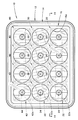
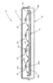
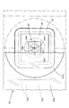
図1は、本願発明の一実施形態に係る車両用前照灯を示す正面図であり、図2は、図1のII-II 線断面図である。
【0027】
これらの図に示すように、本実施形態に係る車両用前照灯10は、ランプボディ12とその前端開口部に取り付けられた素通し状の透光カバー14とで形成される灯室内に、12個の灯具ユニット20、30、40と、これらを支持するユニットホルダ16とが収容された構成となっている。
【0028】
12個の灯具ユニット20、30、40は、4個ずつ上下3段で互いに略等間隔をおいて配置されている。その際、各段に配置された4個の灯具ユニット20、30、40は、いずれも同様の構成を有している。
【0029】
ユニットホルダ16は、透光カバー14の外形形状に略沿って形成された板状部材であって、図示しないエイミング機構を介してランプボディ12に上下方向および左右方向に傾動可能に支持されている。このユニットホルダ16には、各灯具ユニット20、30、40に対応する位置に円形開口部16aが形成されており、これら各円形開口部16aの周囲4箇所には後方へ突出するボス16bが形成されている。そして、これら4箇所のボス16bに対して各灯具ユニット20、30、40が複数のネジ18で締付固定されている。
【0030】
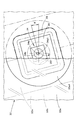
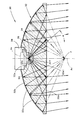
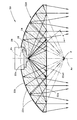
図3は、車両用前照灯10から前方へ照射される光により灯具前方25mの位置に配置された仮想鉛直スクリーン上に形成される配光パターンPを透視的に示す図である。
【0031】
同図に示すように、この配光パターンPは、上端部に水平方向に延びる水平カットオフラインCL1および該水平カットオフラインCL1から所定の角度θで左上方へ延びる斜めカットオフラインCL2を有する左配光のロービーム用配光パターンであって、上記角度θは15°程度の値に設定されている。このロービーム用配光パターンPにおいて、水平カットオフラインCL1と斜めカットオフラインCL2との交点であるエルボ点Eの位置は、灯具正面方向の消点であるH−Vの0.5〜0.6°程度下方の位置に設定されており、このエルボ点Eの左下近傍に高光度領域であるホットゾーンHZが形成されている。
【0032】
なお本実施形態においては、車両用前照灯10をエイミングする際の初期状態において、ユニットホルダ16を予め鉛直面に対して前方側へ0.5〜0.6°傾斜させておくことにより、エルボ点Eの位置を上記位置に設定するようになっている。
【0033】
このロービーム用配光パターンPは、水平カットオフライン形成用パターンP1と、斜めカットオフライン形成用パターンP2と、拡散領域形成用パターンP3との合成配光パターンとして形成されるようになっている。
【0034】
水平カットオフライン形成用パターンP1は、水平カットオフラインCL1を形成するための配光パターンであって、下段に位置する4個の灯具ユニット20からの光照射により形成されるようになっている。斜めカットオフライン形成用パターンP2は、斜めカットオフラインCL2を形成するための配光パターンであって、中段に位置する4個の灯具ユニット30からの光照射により形成されるようになっている。拡散領域形成用パターンP3は、ロービーム用配光パターンPの拡散領域を形成するとともに水平カットオフラインCL1を補助的に形成するための配光パターンであって、上段に位置する4個の灯具ユニット40からの光照射により形成されるようになっている。
【0035】
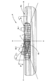
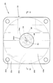
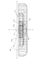
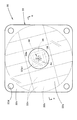
図4は、下段に位置する4個の灯具ユニット20のうちの1個を単品で示す正面図であり、図5は、図4の要部詳細図であり、図6は、図4のVI-VI 線断面図である。
【0036】
これらの図にも示すように、下段に位置する各灯具ユニット20は、発光ダイオードからなる光源24と、この光源24からの光を入射させるように配置された透光部材22と、光源24を基板26を介して支持する支持ブロック28とを備えてなり、車両前後方向に延びる光軸Axを有している。
【0037】
光源24は、正方形の発光チップ24aが半球状の封止樹脂部材24bによって封止されてなり、その発光チップ24aの一辺24a1を、該発光チップ24aの下端部において水平方向に延びるようにした状態で、該一辺24a1を光軸Axと直交させるようにして前向きに配置されている。
【0038】
透光部材22は、アクリル樹脂成形品等の透明な合成樹脂成形品からなり、光源24からの入射光を該透光部材22の前面22aで反射させた後に該透光部材22の後面22bで反射させて該透光部材22の前面22aから出射させるように構成されている。
【0039】
透光部材22の前面22aは、光軸Axと直交する平面で構成されており、その光軸近傍領域22a1には、アルミニウム蒸着等による鏡面処理が施されている。この鏡面処理が施された光軸近傍領域22a1は、透光部材22の前面22aにおいて光軸Axを中心とする円形領域として形成されており、その外周縁の位置は、透光部材22の前面22aに入射する光源24から光の入射角が透光部材22の臨界角αと略同じ値となる位置に設定されている。
【0040】
一方、透光部材22の後面22bは、該透光部材22の前面22aに関して光源24の発光中心と対称の位置を焦点Fとする回転放物面Prを基準面として形成された所定の光反射制御面で構成されており、その全域にわたってアルミニウム蒸着等による鏡面処理が施されている。この光反射制御面は、複数の反射素子22sが縦長の格子状に形成されてなり、これら各反射素子22sにより、透光部材22の前面22aで反射してその後面22bに入射する光源24から光を、発光チップ24aの一辺24a1と平行な方向(すなわち水平方向)に拡散反射させるようになっている。このとき、各反射素子22sは、回転放物面Prに対して水平方向の曲率が僅かに大きい曲面で形成されており、これにより拡散角度を比較的小さい値に設定するようになっている。
【0041】
透光部材22の後面22bには、光源24を取り付けるための光源取付用凹部22eが形成されており、この光源取付用凹部22eの中央部には、光源24の発光中心を半球状に囲む半球状凹部22fが形成されている。そして、この半球状凹部22fの内部空間には、エポキシ樹脂等の透明樹脂50が充填されている。
【0042】
透光部材22の外周部には、90°間隔で4つのタブ22cが形成されており、これら各タブ22cにはネジ挿通孔22dが形成されている。そして、これら各ネジ挿通孔22dにネジ18を挿通させて各タブ22cをユニットホルダ16の各ボス16bに締め付けることにより、発光チップ24aの一辺24a1が水平方向に延びるように位置決めされた状態で、灯具ユニット20のユニットホルダ16への取付けが行われるようになっている。
【0043】
図7は、下段に位置する各灯具ユニット20から前方へ照射される光により上記仮想鉛直スクリーン上に形成される水平カットオフライン形成用パターンP1を示す図である。なお、図3に示す水平カットオフライン形成用パターンP1は、4個の灯具ユニット20によって形成されるので、図7に示す水平カットオフライン形成用パターンP1が4重に重畳されたものとなる。
【0044】
図7において破線で示す配光パターンP1oは、透光部材22の後面22bを構成する光反射制御面が仮に回転放物面Prであるとした場合に形成される基本配光パターンであり、水平カットオフライン形成用パターンP1は、この基本配光パターンP1oを複数の反射素子22sによって水平方向に拡散させたものとなっている。
【0045】
その際、基本配光パターンP1oの上端部の輪郭は、光軸Axと直交するようにして水平方向に延びる発光チップ24aの一辺24a1の反転像として、水平方向に延びる鮮明なカットオフラインCL1oとして形成されるが、それ以外の部分の輪郭は多少不鮮明なものとなる。また、この基本配光パターンP1oは、エルボ点Eに近い部分ほど明るい配光パターンとなる。
【0046】
したがって、この基本配光パターンP1oを水平方向に拡散させることにより得られる水平カットオフライン形成用パターンP1は、上端部に水平カットオフラインCL1を有するとともに、エルボ点Eの近傍にホットゾーンHZ1を有する横長の配光パターンとなる。
【0047】
図8は、中段に位置する4個の灯具ユニット30のうちの1個を単品で示す正面図であり、図9は、図8の要部詳細図であり、図10は、図8のX-X 線断面図である。
【0048】
これらの図にも示すように、中段に位置する各灯具ユニット30は、発光ダイオードからなる光源34と、この光源34からの光を入射させるように配置された透光部材32と、光源34を基板36を介して支持する支持ブロック38とを備えてなり、車両前後方向に延びる光軸Axを有している。
【0049】
光源34は、正方形の発光チップ34aが半球状の封止樹脂部材34bによって封止されてなり、その発光チップ34aの一辺34a1を、該発光チップ34aの下端部において水平方向に対して角度θで灯具正面視において右上方へ延びるようにした状態で、該一辺34a1を光軸Axと直交させるようにして前向きに配置されている。
【0050】
透光部材32は、アクリル樹脂成形品等の透明な合成樹脂成形品からなり、光源34からの入射光を該透光部材32の前面32aで反射させた後に該透光部材32の後面32bで反射させて該透光部材32の前面32aから出射させるように構成されている。
【0051】
透光部材32の前面32aは、光軸Axと直交する平面で構成されており、その光軸近傍領域32a1には、アルミニウム蒸着等による鏡面処理が施されている。この光軸近傍領域32a1は、透光部材32の前面32aにおいて光軸Axを中心とする円形領域として形成されており、その外周縁の位置は、透光部材32の前面32aに入射する光源34から光の入射角が透光部材32の臨界角αと略同じ値となる位置に設定されている。
【0052】
一方、透光部材32の後面32bは、該透光部材32の前面32aに関して光源34の発光中心と対称の位置を焦点Fとする回転放物面Prを基準面として形成された所定の光反射制御面で構成されており、その全域にわたってアルミニウム蒸着等による鏡面処理が施されている。この光反射制御面は、複数の反射素子32sが上記角度θの方向と直交する方向に延びる縦長の格子状に形成されてなり、これら各反射素子32sにより、透光部材32の前面32aで反射して後面32bに入射する光源34から光を、発光チップ34aの一辺34a1と平行な方向(すなわち上記角度θの方向)に拡散偏向反射させるようになっている。このとき、各反射素子32sは、回転放物面Prに対して上記角度θの方向の曲率が僅かに大きい曲面を上記角度θの方向に関して左上方(灯具正面視において右上方)へ多少傾斜させるようにして形成されており、これにより拡散角度を比較的小さい値に設定した上で、透光部材32の前面32aからの光出射方向を上記角度θの方向に沿って左上方へ偏向させるようになっている。
【0053】
透光部材32の後面32bには、光源34を取り付けるための光源取付用凹部32eが形成されており、この光源取付用凹部32eの中央部には、光源34の発光中心を半球状に囲む半球状凹部32fが形成されている。そして、この半球状凹部32fの内部空間には、エポキシ樹脂等の透明樹脂50が充填されている。
【0054】
透光部材32の外周部には、90°間隔で4つのタブ32cが形成されており、これら各タブ32cにはネジ挿通孔32dが形成されている。そして、これら各ネジ挿通孔32dにネジ18を挿通させて各タブ32cをユニットホルダ16の各ボス16bに締め付けることにより、発光チップ34aの一辺34a1が光軸Axと直交する上記角度θの方向に延びるように位置決めされた状態で、灯具ユニット30のユニットホルダ16への取付けが行われるようになっている。
【0055】
図11は、中段に位置する各灯具ユニット30から前方へ照射される光により上記仮想鉛直スクリーン上に形成される斜めカットオフライン形成用パターンP2を示す図である。なお、図3に示す斜めカットオフライン形成用パターンP2は、4個の灯具ユニット30によって形成されるので、図11に示す斜めカットオフライン形成用パターンP2が4重に重畳されたものとなる。
【0056】
図11において破線で示す配光パターンP2oは、透光部材32の後面32bを構成する光反射制御面が仮に回転放物面Prであるとした場合に形成される基本配光パターンであり、斜めカットオフライン形成用パターンP2は、この基本配光パターンP2oを複数の反射素子22sによって上記角度θの方向に拡散させたものとなっている。
【0057】
その際、基本配光パターンP2oの上端部の輪郭は、光軸Axと直交するようにして上記角度θの方向に延びる発光チップ34aの一辺34a1の反転像として、上記角度θの方向に延びる鮮明なカットオフラインCL2oとして形成されるが、それ以外の部分の輪郭は多少不鮮明なものとなる。また、この基本配光パターンP2oは、エルボ点Eに近い部分ほど明るい配光パターンとなる。
【0058】
したがって、この基本配光パターンP1oを上記角度θの方向に拡散させるようにした上でこの角度θの方向に沿って左上方へ偏向させることにより得られる斜めカットオフライン形成用パターンP2は、上端部に斜めカットオフラインCL2を有するとともに、エルボ点Eの近傍にホットゾーンHZ2を有する斜め横長の配光パターンとなる。
【0059】
図1に示すように、上段に位置する各灯具ユニット40は、下段に位置する各灯具ユニット20と略同様の構成となっている。すなわち、各灯具ユニット40は、発光ダイオードからなる光源44と、この光源44からの光を入射させるように配置された透光部材42とを備えている。
光源44は、灯具ユニット20の光源24と全く同様の構成を有しており、その配置も光源24と全く同様である。
【0060】
透光部材42も、その後面に形成された複数の反射素子42s以外の構成は、灯具ユニット20の透光部材22と全く同様である。
【0061】
すなわち、この透光部材42においては、各反射素子42sの水平方向の曲率が、灯具ユニット20の透光部材22の各反射素子22sよりもある程度大きい値に設定されており、これにより透光部材42からの出射光の水平方向の拡散角度を比較的大きい値に設定するようになっている。そしてこれにより、図3に示すように、上端部が水平カットオフラインCL1に沿って水平方向に延びる広拡散の拡散領域形成用パターンP3を形成するようになっている。
次に本実施形態の作用効果について説明する。
【0062】
本実施形態に係る灯具ユニット20において、光源24から透光部材22に入射した光の大半はその前面22aに到達するが、その際、比較的光軸Ax寄りの方向へ向かう光は、鏡面処理が施された光軸近傍領域22a1に入射するので、該光軸近傍領域22a1で反射してその多くが透光部材22の後面22bに入射する。一方、光源24から透光部材22に入射した光のうち光軸Axから大きく離れた方向へ向かう光は、透光部材22の前面22aに対して大きな入射角で入射するので、その大半が前面22aで内面反射して透光部材22の後面22bに入射する。その際、透光部材22の前面22aは光軸Axと直交する平面で構成されているので、透光部材22の後面22bへの入射は、透光部材22の前面22aに関して発光チップ24aと対称の位置を仮想光源とする発散光となるが、透光部材22の後面22bは、仮想光源の位置を焦点Fとする回転放物面Prを基準面として形成された所定の光反射制御面で構成されているので、その後面22bで反射してその前面22aから出射する光の方向を精度良く制御することができる。
【0063】
また、本実施形態に係る灯具ユニット20の光源24は、その発光チップ24aの一辺24a1を該発光チップ24aの下端部に位置させた状態で光軸Axと直交させるようにして前向きに配置されているので、この灯具ユニット20からの光照射により形成される水平カットオフライン形成用パターンP1は、上記一辺24a1の反転像により鮮明な水平カットオフラインCL1を有するものとなる。
【0064】
しかも、本実施形態に係る灯具ユニット20は、その光源24が発光ダイオードで構成されており、この光源24から光を透光部材22の内部で2回反射させて前方へ出射させるように構成されているので、灯具ユニット20を薄型に構成することができる。
【0065】
このように本実施形態によれば、上端部に水平カットオフラインCL1および斜めカットオフラインCL2を有するロービーム用配光パターンPを形成するように構成された車両用前照灯10において、水平カットオフラインCL1を形成するための灯具ユニット20として、薄型の構成で鮮明な水平カットオフラインCL1を形成可能な灯具ユニットを得ることができる。
【0066】
しかも本実施形態においては、透光部材22の前面22aにおける光軸近傍領域22a1に鏡面処理が施されているので、光源24からの光が上向きの直射光として灯具ユニット20の前方へ照射されてしまうのを未然に防止することができ、これにより対向車ドライバ等にグレアを与えてしまうのを効果的に抑制することができる。
【0067】
また本実施形態においては、透光部材22の後面22bを構成する光反射制御面が、該光反射制御面への入射光を発光チップ24aの一辺24a1と平行な水平方向に拡散偏向反射させる複数の反射素子22sで構成されているので、これらによって形成される横長の水平カットオフライン形成用パターンP1により、鮮明な水平カットオフラインCL1を安定的に形成することができ、また、ロービーム用配光パターンPの水平カットオフラインCL1近傍における光度分布を所望する光度分布に設定することが容易に可能となる。
【0068】
本実施形態においては、透光部材22の前面22aにおいて鏡面処理が施された光軸近傍領域22a1が円形に形成されており、その外周縁の位置が、透光部材22の前面22aに入射する光源24から光の入射角が該透光部材22の臨界角αと略同じ値となる位置に設定されているので、該光軸近傍領域22a1の存在によって透光部材22の後面22bからの反射光を必要以上に遮蔽してしまうことなく、透光部材22の前面22aに入射する光源24からの光の略全量を該前面22aで反射させることができ、これにより光束利用効率を高めることができる。
【0069】
また本実施形態においては、斜めカットオフラインCL2を形成するための灯具ユニット30についても、上記灯具ユニット20と略同様の構成を有しているので、これを薄型に構成した上で鮮明な斜めカットオフラインCL2を形成することができる。
【0070】
さらに本実施形態においては、ロービーム用配光パターンPの拡散領域を形成するとともに水平カットオフラインCL1を補助的に形成するための灯具ユニット40についても、上記灯具ユニット20と略同様の構成を有しているので、これを薄型に構成した上で拡散領域を形成するとともに水平カットオフラインCL1を補助的に形成することができる。
【0071】
そして本実施形態においては、灯室内に収容されている12個の灯具ユニット20、30、40が、すべて薄型に構成されているので、車両用前照灯10としても薄型化を図ることができる。
【0072】
また本実施形態においては、透光部材22の後面22bに形成された光源取付用凹部22eの中央部に、光源24の発光中心を半球状に囲む半球状凹部22fが形成されているので、光源24からの光を透光部材22に対して略垂直に入射させることができる。そしてこれにより、光源24から透光部材22に入射する光を界面で不用意に屈折させてしまうことなく直進させることができるので、灯具ユニット20の照射光制御を容易化することができる。しかも、半球状凹部22fの内部空間には透明樹脂50が充填されているので、光源24の封止樹脂部材24bと透光部材22との間に空気層を介在させないようにすることができ、これにより界面での反射光を最小限に抑えて光束利用率を高めることができる。
【0073】
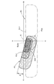
上記実施形態に係る灯具ユニット20において、その透光部材22に代えて、図12に示すような、光源24の封止樹脂部材で構成された透光部材22Aを採用することも可能である。このような構成を採用した場合には、灯具ユニット20を光源ユニットとして一層簡易な構成とすることができ、また、光源24の発光チップ24aと透光部材22Aとの間に空気層が介在しないので、光源光束を有効に利用することができる。
【0074】
上記実施形態においては、下段に配置された4個の灯具ユニット20が、いずれも同様の構成を有しているものとして説明したが、各灯具ユニット20相互間において各反射素子22sの曲率等を異なった値に設定して水平方向の拡散角度等を適当に変化させるようにしてもよい。このような構成を採用した場合には、水平カットオフライン形成用パターンP1を一層光ムラの少ないものとすることができる。中段に配置された4個の灯具ユニット30および上段に配置された4個の灯具ユニット40についても同様である。
【0075】
上記実施形態においては、12個の灯具ユニット20、30、40が4個ずつ上下3段で互いに略等間隔をおいて配置されているものとして説明したが、これら灯具ユニット20、30、40の個数および配置等は、狙いとする配光パターンの形状や光度分布等に応じて適宜変更してよいことはもちろんである。
【図面の簡単な説明】
【図1】本願発明の一実施形態に係る車両用前照灯を示す正面図
【図2】図1のII-II 線断面図
【図3】上記車両用前照灯から前方へ照射される光により灯具前方25mの位置に配置された仮想鉛直スクリーン上に形成される配光パターンを透視的に示す図
【図4】上記車両用前照灯において下段に位置する4個の灯具ユニットのうちの1個を単品で示す正面図
【図5】図4の要部詳細図
【図6】図4のVI-VI 線断面図
【図7】下段に位置する各灯具ユニットから前方へ照射される光により上記仮想鉛直スクリーン上に形成される水平カットオフライン形成用パターンを示す図
【図8】上記車両用前照灯において中段に位置する4個の灯具ユニットのうちの1個を単品で示す正面図
【図9】図8の要部詳細図
【図10】図8のX-X 線断面図
【図11】中段に位置する各灯具ユニットから前方へ照射される光により上記仮想鉛直スクリーン上に形成される斜めカットオフライン形成用パターンを示す図
【図12】上記実施形態の変形例を示す、図6と同様の図
【符号の説明】
10 車両用前照灯
12 ランプボディ
14 透光カバー
16 ユニットホルダ
16a 円形開口部
16b ボス
20、30、40 灯具ユニット
22、22A、32、42 透光部材
22a、32a 前面
22a1、32a1 光軸近傍領域
22b、32b 後面
22c、32c タブ
22d、32d ネジ挿通孔
22e、32e 光源取付用凹部
22f、32f 半球状凹部
22s、32s、42s 反射素子
24、34、44 光源
24a、34a 発光チップ
24a1、34a1 一辺
24b、34b 封止樹脂部
26、36 基板
28、38 支持ブロック
50 透明樹脂
Ax 光軸
CL1 水平カットオフライン
CL2 斜めカットオフライン
CL1o、CL2o カットオフライン
E エルボ点
F 焦点
HZ、HZ1、HZ2 ホットゾーン
P ロービーム用配光パターン
P1 水平カットオフライン形成用パターン
P2 斜めカットオフライン形成用パターン
P3 拡散領域形成用パターン
P1o、P2o 基本配光パターン
Pr 回転放物面[0001]
BACKGROUND OF THE INVENTION
The present invention relates to a lamp unit or the like used for forming a straight line portion of a cut-off line in a vehicle headlamp.
[0002]
[Prior art]
Conventionally, as described in, for example, “Patent Document 1”, a light distribution pattern having a predetermined cut-off line at the upper end portion is formed by performing diffuse reflection control of light from a light source with a reflector. Vehicle headlamps are known.
[0003]
Further, in “Patent Document 2”, light from a light-emitting chip of a light-emitting diode is reflected on the front surface of the sealing resin member and then reflected on the rear surface of the sealing resin member. An optical device configured to emit is described.
[0004]
[Patent Document 1]
JP 2001-351410 A
[Patent Document 2]
JP 2002-94129 A
[Problems to be solved by the invention]
If the optical device described in the above-mentioned “Patent Document 2” is used as a lamp unit for a vehicle headlamp, the lamp unit can be made thin.
[0005]
However, since the light distribution pattern formed by light irradiation from the optical device described in the above-mentioned “Patent Document 2” has a considerably unclear outline, this optical device is used as a lamp for forming a cut-off line. There is a problem that it cannot be used as a unit.
[0006]
The present invention has been made in view of such circumstances, and as a lamp unit used for forming a straight line portion of a cut-off line in a vehicle headlamp, a clear cut-off line is formed with a thin structure. The object is to provide a possible lamp unit or the like.
[0007]
[Means for Solving the Problems]
The present invention uses a semiconductor light emitting element as a light source, and after arranging a light transmissive member so that light from the light source is incident, the invention is devised in the arrangement of the light source and the structure of the light transmissive member. It aims to achieve the purpose.
[0008]
That is, the vehicle headlamp according to the present invention is
In a vehicle headlamp configured to form a light distribution pattern having a predetermined cut-off line at the upper end, a lamp unit used to form a straight line portion of the cut-off line,
A light source comprising a semiconductor light-emitting element having a light-emitting chip extending linearly on one side, and a translucent member arranged so that light from the light source is incident,
The light source is disposed facing forward so that the one side is perpendicular to the optical axis of the lamp unit in a state where one side of the light emitting chip is positioned at the lower end of the light emitting chip.
The translucent member is configured to reflect incident light from the light source on the front surface of the translucent member and then reflect the incident light on the rear surface of the translucent member to be emitted from the front surface of the translucent member,
The front surface of the translucent member is configured by a plane orthogonal to the optical axis, and the rear surface of the translucent member rotates with a focus on a position symmetrical to the light emission center of the light source with respect to the front surface of the translucent member. It consists of a predetermined light reflection control surface formed with a parabolic surface as a reference surface,
A mirror surface treatment is performed on a region near the optical axis on the front surface of the light transmissive member, and a mirror surface treatment is performed on the rear surface of the light transmissive member.
[0009]
The specific shape of the “predetermined cut-off line” is not particularly limited. For example, a shape including a horizontal cut-off line extending in the horizontal direction and an oblique cut-off line extending obliquely upward from the horizontal cut-off line, left and right It is possible to adopt a shape in which a pair of horizontal cut-off lines are formed in a stepped shape with different steps.
[0010]
The specific position of the “cut-off line straight line portion” is not particularly limited. For example, a straight line portion extending in the horizontal direction or a straight line portion extending obliquely at a predetermined angle with respect to the horizontal direction can be employed. is there.
The type of the “semiconductor light emitting element” is not particularly limited, and for example, a light emitting diode or a laser diode can be employed.
[0011]
The shape of the “light emitting chip” is not particularly limited as long as one side is formed so as to extend linearly. For example, a square, a rectangle, a parallelogram, a hexagon, a semicircle, etc. Can be adopted.
[0012]
The specific shape of the “predetermined light reflection control surface formed with the rotational paraboloid as a reference surface” is not particularly limited. For example, the rotational paraboloid is composed of the rotational paraboloid itself. It is possible to adopt a structure in which a plurality of reflective elements are formed, a structure in which a rotating paraboloid is deformed, or the like.
[0013]
The above-mentioned “mirror treatment” means a treatment for enabling specular reflection, and it is a matter of course that the mirror treatment may be performed by a surface treatment such as aluminum vapor deposition. It is also possible to apply a mirror surface treatment by pasting.
[0014]
[Effects of the invention]
As shown in the above configuration, the lamp unit according to the present invention includes a light source composed of a semiconductor light-emitting element having a light-emitting chip extending linearly on one side, and a translucent member arranged so that light from the light source is incident thereon. And is used for forming a straight line portion of a cut-off line in a vehicle headlamp. The light source has one side in a state where one side of the light emitting chip is positioned at the lower end. Is arranged so as to be orthogonal to the optical axis of the lamp unit, and the translucent member reflects the incident light from the light source on the front surface and then reflects it on the rear surface and emits it from the front surface. In this case, the front surface of the translucent member is configured by a plane orthogonal to the optical axis, and the rear surface of the translucent member focuses on a position symmetrical to the light emission center of the light source with respect to the front surface. It is composed of a predetermined light reflection control surface formed with a paraboloid of revolution as a reference surface, and a mirror surface treatment is applied to a region in the vicinity of the optical axis on the front surface of the light transmissive member and a mirror surface is provided on the rear surface of the light transmissive member. Since the process is performed, the following effects can be obtained.
[0015]
That is, most of the light incident on the translucent member from the light source reaches the front surface, but at that time, the light traveling in the direction closer to the optical axis is incident on the region near the optical axis that has undergone the mirror treatment. The light is reflected in the region near the optical axis and most of the light is incident on the rear surface of the translucent member. On the other hand, the light that travels in a direction far away from the optical axis out of the light incident on the light transmissive member from the light source is incident on the front surface of the light transmissive member at a large incident angle. Incident on the rear surface of the translucent member. At this time, since the front surface of the translucent member is configured by a plane orthogonal to the optical axis, the incident light to the rear surface of the translucent member uses a position symmetrical to the light emitting chip with respect to the front surface of the translucent member as a virtual light source. Although it becomes diverging light, the rear surface of the translucent member is composed of a predetermined light reflection control surface formed with a rotating paraboloid focusing on the position of the virtual light source as a reference surface, and is reflected on the rear surface. The direction of light emitted from the front surface of the lever can be controlled with high accuracy.
[0016]
Further, since the light source of the lamp unit according to the present invention is disposed forward so as to be orthogonal to the optical axis in a state where one side of the light-emitting chip is positioned at the lower end portion of the light-emitting chip, The light distribution pattern formed by this light irradiation has a clear cut-off line due to the inverted image of the one side.
[0017]
In addition, the lamp unit according to the present invention is configured such that the light source is composed of a semiconductor light emitting element, and the light is reflected from the light source twice inside the translucent member and emitted forward. The lamp unit can be configured to be thin.
[0018]
As described above, according to the present invention, a lamp unit that can form a clear cut-off line with a thin configuration can be obtained as a lamp unit used to form a straight-line portion of a cut-off line in a vehicle headlamp. .
[0019]
Furthermore, since the lamp unit according to the present invention is mirror-finished in the vicinity of the optical axis on the front surface of the translucent member, the light from the light source is irradiated to the front of the lamp unit as upward direct light. Therefore, it is possible to effectively prevent glare from being imparted to the oncoming vehicle driver and the like.
[0020]
In the above configuration, if the light reflection control surface constituting the rear surface of the translucent member is configured to diffusely reflect light incident on the light reflection control surface in a direction parallel to one side of the light emitting chip, it becomes a cut-off line. It is possible to easily form a sharp cut-off line by forming a light distribution pattern extending long along the line, or to easily set a light intensity distribution near the cut-off line of the light distribution pattern to a desired light intensity distribution.
[0021]
Here, “diffuse, deflect and reflect in a direction parallel to one side of the light emitting chip” means that the reflected light is diffused in a direction parallel to one side of the light emitting chip, and the reflected light is deflected in a direction parallel to one side of the light emitting chip. And that these diffusion and deflection are performed simultaneously.
[0022]
In the above configuration, the size and shape of the “near optical axis region” subjected to the mirror treatment on the front surface of the translucent member is not particularly limited, but the position of the outer peripheral edge of this “near optical axis region” If the incident angle of light from the light source incident on the front surface of the translucent member is set at a position where the critical angle of the translucent member is approximately the same value, the rear surface of the translucent member due to the presence of the region near the optical axis The light from the light source incident on the front surface of the translucent member can be reflected by the front surface without blocking the reflected light from the light more than necessary, thereby improving the luminous efficiency. .
[0023]
By the way, in the light source which consists of a semiconductor light-emitting element, it has the structure provided with the sealing resin member for sealing a light emitting chip | tip in many cases, but a translucent member may also be comprised with this sealing resin member. Is possible. In this case, the lamp unit can be a simpler configuration as a light source unit, and an air layer can be prevented from interposing between the light source and the translucent member. Can be used effectively.
If the configuration of the vehicle headlamp includes a plurality of lamp units according to the present invention, the vehicle headlamp as a whole can be thinned.
[0024]
At this time, a part of the plurality of lamp units is configured as a lamp unit for forming a horizontal cut-off line having a light source arranged such that one side of the light emitting chip extends in the horizontal direction as the light source, and at least the other If a part of the light emitting chip is configured as a lamp unit for forming an oblique cut-off line arranged so that one side of the light-emitting chip extends in a direction inclined by a predetermined angle with respect to the horizontal direction, the horizontal cut-off line and the oblique line are formed at the upper end. A light distribution pattern suitable for a vehicle headlamp having a cut-off line can be obtained.
[0025]
DETAILED DESCRIPTION OF THE INVENTION
Hereinafter, embodiments of the present invention will be described with reference to the drawings.
[0026]
FIG. 1 is a front view showing a vehicle headlamp according to an embodiment of the present invention, and FIG. 2 is a cross-sectional view taken along the line II-II in FIG.
[0027]
As shown in these drawings, a
[0028]
The twelve
[0029]
The
[0030]
FIG. 3 is a perspective view showing a light distribution pattern P formed on a virtual vertical screen arranged at a position 25 m ahead of the lamp by light irradiated forward from the
[0031]
As shown in the figure, this light distribution pattern P has a left light distribution having a horizontal cut-off line CL1 extending in the horizontal direction at the upper end and an oblique cut-off line CL2 extending upward from the horizontal cut-off line CL1 at a predetermined angle θ. The light distribution pattern for low beam, and the angle θ is set to a value of about 15 °. In this low beam distribution pattern P, the position of the elbow point E, which is the intersection of the horizontal cutoff line CL1 and the oblique cutoff line CL2, is 0.5 to 0.6 ° of HV, which is the vanishing point in the front direction of the lamp. A hot zone HZ that is a high luminous intensity region is formed near the lower left of the elbow point E.
[0032]
In the present embodiment, in the initial state when aiming the
[0033]
The low beam light distribution pattern P is formed as a combined light distribution pattern of a horizontal cut-off line formation pattern P1, an oblique cut-off line formation pattern P2, and a diffusion region formation pattern P3.
[0034]
The horizontal cut-off line formation pattern P1 is a light distribution pattern for forming the horizontal cut-off line CL1, and is formed by light irradiation from the four
[0035]
4 is a front view showing one of the four
[0036]
As shown in these figures, each
[0037]
In the
[0038]
The
[0039]
The
[0040]
On the other hand, the
[0041]
A light
[0042]
Four
[0043]
FIG. 7 is a diagram showing a horizontal cut-off line forming pattern P1 formed on the virtual vertical screen by light irradiated forward from each
[0044]
A light distribution pattern P1o indicated by a broken line in FIG. 7 is a basic light distribution pattern formed when the light reflection control surface constituting the
[0045]
At this time, the outline of the upper end portion of the basic light distribution pattern P1o is formed as a sharp cut-off line CL1o extending in the horizontal direction as an inverted image of one side 24a1 of the
[0046]
Accordingly, the horizontal cut-off line forming pattern P1 obtained by diffusing the basic light distribution pattern P1o in the horizontal direction has a horizontal cut-off line CL1 at the upper end and a horizontal elongated shape having a hot zone HZ1 in the vicinity of the elbow point E. The light distribution pattern is as follows.
[0047]
FIG. 8 is a front view showing one of the four
[0048]
As shown in these figures, each
[0049]
In the
[0050]
The
[0051]
The
[0052]
On the other hand, the
[0053]
A light
[0054]
Four
[0055]
FIG. 11 is a diagram showing an oblique cut-off line forming pattern P2 formed on the virtual vertical screen by light irradiated forward from each
[0056]
A light distribution pattern P2o indicated by a broken line in FIG. 11 is a basic light distribution pattern formed when the light reflection control surface constituting the
[0057]
At that time, the contour of the upper end portion of the basic light distribution pattern P2o is a sharp image extending in the direction of the angle θ as an inverted image of one side 34a1 of the
[0058]
Therefore, the oblique light cut-off line forming pattern P2 obtained by diffusing the basic light distribution pattern P1o in the direction of the angle θ and deflecting the basic light distribution pattern P1o in the upper left direction along the direction of the angle θ And an oblique horizontal light distribution pattern having a hot zone HZ2 in the vicinity of the elbow point E.
[0059]
As shown in FIG. 1, each
The light source 44 has the same configuration as that of the
[0060]
The configuration of the
[0061]
That is, in this
Next, the effect of this embodiment is demonstrated.
[0062]
In the
[0063]
Further, the
[0064]
Moreover, the
[0065]
As described above, according to the present embodiment, in the
[0066]
In addition, in the present embodiment, since the optical axis vicinity region 22a1 on the
[0067]
In the present embodiment, the light reflection control surface constituting the
[0068]
In the present embodiment, the optical axis vicinity region 22a1 that has been subjected to the mirror finish on the
[0069]
In the present embodiment, the
[0070]
Furthermore, in the present embodiment, the
[0071]
In the present embodiment, since the twelve
[0072]
In the present embodiment, a
[0073]
In the
[0074]
In the above embodiment, the four
[0075]
In the above-described embodiment, the 12
[Brief description of the drawings]
FIG. 1 is a front view showing a vehicle headlamp according to an embodiment of the present invention.
2 is a cross-sectional view taken along line II-II in FIG.
FIG. 3 is a perspective view showing a light distribution pattern formed on a virtual vertical screen disposed at a position 25 m ahead of the lamp by light emitted forward from the vehicle headlamp.
FIG. 4 is a front view showing one of four lamp units located in the lower stage of the vehicle headlamp as a single item;
FIG. 5 is a detailed view of the main part of FIG.
6 is a cross-sectional view taken along line VI-VI in FIG.
FIG. 7 is a view showing a horizontal cut-off line forming pattern formed on the virtual vertical screen by light irradiated forward from each lamp unit located in the lower stage;
FIG. 8 is a front view showing one of four lamp units located in the middle stage of the vehicle headlamp as a single item;
FIG. 9 is a detailed view of the main part of FIG.
10 is a sectional view taken along line XX in FIG.
FIG. 11 is a diagram showing an oblique cut-off line forming pattern formed on the virtual vertical screen by light irradiated forward from each lamp unit located in the middle stage;
FIG. 12 is a view similar to FIG. 6, showing a modification of the embodiment.
[Explanation of symbols]
10 Vehicle headlamps
12 Lamp body
14 Translucent cover
16 Unit holder
16a Circular opening
16b boss
20, 30, 40 Lamp unit
22, 22A, 32, 42 Translucent member
22a, 32a front
22a1, 32a1 Area near the optical axis
22b, 32b Rear surface
22c, 32c tab
22d, 32d Screw insertion hole
22e, 32e Light source mounting recess
22f, 32f hemispherical recess
22s, 32s, 42s Reflective element
24, 34, 44 Light source
24a, 34a Light emitting chip
24a1, 34a1 side
24b, 34b Sealing resin part
26, 36 substrates
28, 38 Support block
50 Transparent resin
Ax optical axis
CL1 horizontal cut offline
CL2 diagonal cut offline
CL1o, CL2o cut-off line
E Elbow point
F Focus
HZ, HZ1, HZ2 hot zone
P Light distribution pattern for low beam
P1 Horizontal cut-off line forming pattern
P2 Diagonal cut-off line formation pattern
P3 Diffusion area formation pattern
P1o, P2o basic light distribution pattern
Pr rotating paraboloid
Claims (5)
一辺が直線状に延びる発光チップを有する半導体発光素子からなる光源と、この光源からの光を入射させるように配置された透光部材とを備えてなり、
上記光源が、上記発光チップの一辺を該発光チップの下端部に位置させた状態で該一辺を上記灯具ユニットの光軸と直交させるようにして前向きに配置されており、
上記透光部材が、上記光源からの入射光を該透光部材の前面で反射させた後に該透光部材の後面で反射させて該透光部材の前面から出射させるように構成されており、
上記透光部材の前面が、上記光軸と直交する平面で構成されるとともに、上記透光部材の後面が、該透光部材の前面に関して上記光源の発光中心と対称の位置を焦点とする回転放物面を基準面として形成された所定の光反射制御面で構成されており、
上記透光部材の前面における光軸近傍領域に鏡面処理が施されるとともに、上記透光部材の後面に鏡面処理が施されている、ことを特徴とする灯具ユニット。In a vehicle headlamp configured to form a light distribution pattern having a predetermined cut-off line at the upper end, a lamp unit used to form a straight line portion of the cut-off line,
A light source comprising a semiconductor light-emitting element having a light-emitting chip extending linearly on one side, and a translucent member arranged so that light from the light source is incident,
The light source is disposed facing forward so that the one side is perpendicular to the optical axis of the lamp unit in a state where one side of the light emitting chip is positioned at the lower end of the light emitting chip.
The translucent member is configured to reflect incident light from the light source on the front surface of the translucent member and then reflect the incident light on the rear surface of the translucent member to be emitted from the front surface of the translucent member,
The front surface of the translucent member is configured by a plane orthogonal to the optical axis, and the rear surface of the translucent member rotates with a focus on a position symmetrical to the light emission center of the light source with respect to the front surface of the translucent member. It consists of a predetermined light reflection control surface formed with a parabolic surface as a reference surface,
A lamp unit characterized in that a mirror surface treatment is performed on a region near the optical axis on the front surface of the light transmissive member, and a mirror surface treatment is performed on the rear surface of the light transmissive member.
上記複数個の灯具ユニットの一部が、上記光源として上記発光チップの一辺が水平方向に延びるように配置された光源を有する水平カットオフライン形成用の灯具ユニットとして構成されており、
上記複数個の灯具ユニットの他の少なくとも一部が、上記光源として上記発光チップの一辺が水平方向に対して所定角度傾斜した方向に延びるように配置された斜めカットオフライン形成用の灯具ユニットとして構成されている、ことを特徴とする車両用前照灯。A vehicle headlamp comprising a plurality of lamp units according to any one of claims 1 to 4,
A part of the plurality of lamp units is configured as a lamp unit for forming a horizontal cut-off line having a light source arranged so that one side of the light emitting chip extends in the horizontal direction as the light source.
At least another part of the plurality of lamp units is configured as a lamp unit for forming an oblique cut-off line arranged so that one side of the light emitting chip as a light source extends in a direction inclined at a predetermined angle with respect to a horizontal direction. A vehicle headlamp characterized by the above.
Priority Applications (2)
| Application Number | Priority Date | Filing Date | Title |
|---|---|---|---|
| JP2003175213A JP4339028B2 (en) | 2003-06-19 | 2003-06-19 | Lamp unit and vehicle headlamp |
| US10/870,148 US7070312B2 (en) | 2003-06-19 | 2004-06-18 | Lamp unit and vehicle headlamp using the same |
Applications Claiming Priority (1)
| Application Number | Priority Date | Filing Date | Title |
|---|---|---|---|
| JP2003175213A JP4339028B2 (en) | 2003-06-19 | 2003-06-19 | Lamp unit and vehicle headlamp |
Publications (2)
| Publication Number | Publication Date |
|---|---|
| JP2005011704A JP2005011704A (en) | 2005-01-13 |
| JP4339028B2 true JP4339028B2 (en) | 2009-10-07 |
Family
ID=33516224
Family Applications (1)
| Application Number | Title | Priority Date | Filing Date |
|---|---|---|---|
| JP2003175213A Expired - Fee Related JP4339028B2 (en) | 2003-06-19 | 2003-06-19 | Lamp unit and vehicle headlamp |
Country Status (2)
| Country | Link |
|---|---|
| US (1) | US7070312B2 (en) |
| JP (1) | JP4339028B2 (en) |
Cited By (3)
| Publication number | Priority date | Publication date | Assignee | Title |
|---|---|---|---|---|
| EP2503224A2 (en) | 2011-03-25 | 2012-09-26 | Stanley Electric Co., Ltd. | Vehicle lighting unit |
| US8529109B2 (en) | 2010-05-21 | 2013-09-10 | Stanley Electric Co., Ltd. | Vehicle lightening unit |
| US9689546B2 (en) | 2011-03-25 | 2017-06-27 | Light Prescriptions Innovators, Llc | Vehicle lighting unit |
Families Citing this family (42)
| Publication number | Priority date | Publication date | Assignee | Title |
|---|---|---|---|---|
| US20080055896A1 (en) * | 2006-08-30 | 2008-03-06 | David Charles Feldmeier | Systems, devices, components and methods for controllably configuring the color of light emitted by an automotive LED illumination system |
| US20080055065A1 (en) * | 2006-08-30 | 2008-03-06 | David Charles Feldmeier | Systems, devices, components and methods for controllably configuring the brightness of light emitted by an automotive LED illumination system |
| TW200830593A (en) * | 2006-11-15 | 2008-07-16 | Univ California | Transparent mirrorless light emitting diode |
| RU2446348C2 (en) * | 2006-11-27 | 2012-03-27 | Филипс Солид-Стейт Лайтинг Солюшнз, Инк. | Method and apparatus for formation of uniform projection illumination |
| WO2008073400A1 (en) | 2006-12-11 | 2008-06-19 | The Regents Of The University Of California | Transparent light emitting diodes |
| JP5253888B2 (en) | 2008-02-22 | 2013-07-31 | 株式会社小糸製作所 | Lighting fixtures for vehicles |
| JP5350771B2 (en) * | 2008-12-24 | 2013-11-27 | 株式会社小糸製作所 | Lighting fixtures for vehicles |
| US8508688B2 (en) | 2009-02-12 | 2013-08-13 | Panasonic Corporation | Illuminating lens, lighting device, surface light source, and liquid-crystal display apparatus |
| US8582053B2 (en) | 2009-02-12 | 2013-11-12 | Panasonic Corporation | Illuminating lens, lighting device, surface light source, and liquid-crystal display apparatus |
| US8576351B2 (en) | 2009-02-12 | 2013-11-05 | Panasonic Corporation | Illuminating lens, lighting device, surface light source, and liquid-crystal display apparatus |
| JP5342938B2 (en) * | 2009-06-19 | 2013-11-13 | パナソニック株式会社 | Lighting lens, light emitting device, surface light source, and liquid crystal display device |
| US8469554B2 (en) | 2009-02-12 | 2013-06-25 | Panasonic Corporation | Illuminating lens, lighting device, surface light source, and liquid-crystal display apparatus |
| US8558967B2 (en) | 2009-02-12 | 2013-10-15 | Panasonic Corporation | Illuminating lens, lighting device, surface light source, and liquid-crystal display apparatus |
| JP5342940B2 (en) * | 2009-06-19 | 2013-11-13 | パナソニック株式会社 | Lighting lens, light emitting device, surface light source, and liquid crystal display device |
| JP5603565B2 (en) * | 2009-04-30 | 2014-10-08 | 株式会社小糸製作所 | Vehicle lighting |
| JP5387897B2 (en) * | 2009-06-19 | 2014-01-15 | スタンレー電気株式会社 | Vehicle lighting |
| JP5370660B2 (en) | 2009-06-19 | 2013-12-18 | スタンレー電気株式会社 | Vehicle lighting |
| JP5497408B2 (en) * | 2009-11-09 | 2014-05-21 | 株式会社小糸製作所 | Vehicle headlamp |
| DE102010005388B4 (en) * | 2010-01-22 | 2019-12-05 | Automotive Lighting Reutlingen Gmbh | Automotive lighting device with semiconductor light sources for a plurality of light functions |
| JP5518606B2 (en) * | 2010-07-08 | 2014-06-11 | 株式会社小糸製作所 | Lighting fixtures for vehicles |
| JP5518607B2 (en) * | 2010-07-08 | 2014-06-11 | 株式会社小糸製作所 | Lighting fixtures for vehicles |
| JP5567435B2 (en) * | 2010-09-06 | 2014-08-06 | 株式会社小糸製作所 | Vehicle lighting |
| USD648644S1 (en) * | 2010-11-19 | 2011-11-15 | Lg Innotek Co., Ltd. | Reflector |
| USD647811S1 (en) * | 2010-11-19 | 2011-11-01 | Lg Innotek Co., Ltd. | Reflector |
| USD648240S1 (en) * | 2010-11-19 | 2011-11-08 | Lg Innotek Co., Ltd. | Reflector |
| USD672677S1 (en) * | 2010-11-19 | 2012-12-18 | Lg Innotek Co., Ltd. | Reflector |
| USD647416S1 (en) * | 2010-11-19 | 2011-10-25 | Lg Innotek Co., Ltd. | Reflector |
| USD673067S1 (en) * | 2010-11-19 | 2012-12-25 | Lg Innotek Co., Ltd. | Reflector |
| JP5944617B2 (en) | 2011-02-08 | 2016-07-05 | 株式会社小糸製作所 | Lamp unit |
| JP5538307B2 (en) | 2011-06-21 | 2014-07-02 | 本田技研工業株式会社 | Lamp body and vehicle lamp unit |
| JP5839677B2 (en) * | 2011-11-18 | 2016-01-06 | 株式会社小糸製作所 | Lighting fixtures for vehicles |
| CN103133964A (en) * | 2011-11-29 | 2013-06-05 | 株式会社小糸制作所 | Vehicle lamp |
| JP5955110B2 (en) | 2012-06-05 | 2016-07-20 | 株式会社小糸製作所 | Vehicle lighting |
| JP5990410B2 (en) | 2012-06-11 | 2016-09-14 | 株式会社小糸製作所 | Mobile lighting |
| JP5988764B2 (en) * | 2012-08-10 | 2016-09-07 | 株式会社小糸製作所 | Lighting fixtures for vehicles |
| JP6250289B2 (en) | 2013-02-07 | 2017-12-20 | 株式会社小糸製作所 | Optical surface determination method |
| JP2015099336A (en) * | 2013-11-20 | 2015-05-28 | 株式会社東芝 | Optical element and optical device |
| JP5786068B2 (en) * | 2014-06-10 | 2015-09-30 | スタンレー電気株式会社 | Vehicle lamp unit |
| JP6910226B2 (en) * | 2017-07-07 | 2021-07-28 | Hoya株式会社 | Light irradiation device |
| CN107454718B (en) * | 2017-08-31 | 2023-11-28 | 广州光联电子科技有限公司 | An LED light source and optical system with color temperature correction function |
| JP7339013B2 (en) * | 2019-04-01 | 2023-09-05 | 株式会社小糸製作所 | vehicle lamp |
| WO2025001609A1 (en) * | 2023-06-28 | 2025-01-02 | 深圳市神牛摄影器材有限公司 | Photographing panel lamp |
Family Cites Families (9)
| Publication number | Priority date | Publication date | Assignee | Title |
|---|---|---|---|---|
| US5173810A (en) * | 1991-08-21 | 1992-12-22 | Aisens Co., Ltd. | Light transmitting lens for use with a photoelectric sensor |
| JP2002094129A (en) | 1999-11-30 | 2002-03-29 | Omron Corp | Optical device and equipment using the optical device |
| DE10009782B4 (en) * | 2000-03-01 | 2010-08-12 | Automotive Lighting Reutlingen Gmbh | Lighting device of a vehicle |
| AU2001249256A1 (en) * | 2000-03-16 | 2001-09-24 | Pablo Benitez | High efficiency non-imaging optics |
| JP2001351410A (en) | 2000-06-06 | 2001-12-21 | Koito Mfg Co Ltd | Vehicle headlights |
| US6552368B2 (en) * | 2000-09-29 | 2003-04-22 | Omron Corporation | Light emission device |
| JP4040955B2 (en) * | 2002-11-06 | 2008-01-30 | 株式会社小糸製作所 | Vehicle headlamp and manufacturing method thereof |
| JP4002207B2 (en) * | 2003-04-21 | 2007-10-31 | 株式会社小糸製作所 | Vehicle headlamp |
| JP4245968B2 (en) * | 2003-04-23 | 2009-04-02 | 株式会社小糸製作所 | Vehicle headlamp |
-
2003
- 2003-06-19 JP JP2003175213A patent/JP4339028B2/en not_active Expired - Fee Related
-
2004
- 2004-06-18 US US10/870,148 patent/US7070312B2/en not_active Expired - Lifetime
Cited By (4)
| Publication number | Priority date | Publication date | Assignee | Title |
|---|---|---|---|---|
| US8529109B2 (en) | 2010-05-21 | 2013-09-10 | Stanley Electric Co., Ltd. | Vehicle lightening unit |
| EP2503224A2 (en) | 2011-03-25 | 2012-09-26 | Stanley Electric Co., Ltd. | Vehicle lighting unit |
| US9188298B2 (en) | 2011-03-25 | 2015-11-17 | Stanley Electric Co., Ltd. | Vehicle lighting unit |
| US9689546B2 (en) | 2011-03-25 | 2017-06-27 | Light Prescriptions Innovators, Llc | Vehicle lighting unit |
Also Published As
| Publication number | Publication date |
|---|---|
| US7070312B2 (en) | 2006-07-04 |
| JP2005011704A (en) | 2005-01-13 |
| US20040257826A1 (en) | 2004-12-23 |
Similar Documents
| Publication | Publication Date | Title |
|---|---|---|
| JP4339028B2 (en) | Lamp unit and vehicle headlamp | |
| JP5567435B2 (en) | Vehicle lighting | |
| JP5253888B2 (en) | Lighting fixtures for vehicles | |
| JP4024628B2 (en) | Vehicle headlamp | |
| JP4002159B2 (en) | Vehicle headlamp | |
| JP3986779B2 (en) | Vehicle lighting | |
| JP4068387B2 (en) | Light source unit | |
| JP4970136B2 (en) | Vehicle headlamp lamp unit | |
| JP4393971B2 (en) | Lighting fixtures for vehicles | |
| CN113286967B (en) | Optical unit | |
| US20050162857A1 (en) | Lamp unit for vehicle and illumination lamp for vehicle | |
| US7866863B2 (en) | Vehicle lamp | |
| JP2006127856A (en) | Lighting fixtures for vehicles | |
| JP2004327095A (en) | Vehicle headlights | |
| JP2012089333A (en) | Lamp for vehicle | |
| JP2010153076A (en) | Vehicular illumination lamp | |
| JP5839677B2 (en) | Lighting fixtures for vehicles | |
| JP5097653B2 (en) | Lighting fixtures for vehicles | |
| JP5518607B2 (en) | Lighting fixtures for vehicles | |
| JP7625982B2 (en) | Lens for vehicle lighting, vehicle lighting unit, and vehicle lighting device | |
| JP6717646B2 (en) | Vehicle lighting | |
| EP3633264B1 (en) | Optical unit | |
| JP5603565B2 (en) | Vehicle lighting | |
| JP5640703B2 (en) | Vehicle lighting |
Legal Events
| Date | Code | Title | Description |
|---|---|---|---|
| A621 | Written request for application examination |
Free format text: JAPANESE INTERMEDIATE CODE: A621 Effective date: 20050929 |
|
| A977 | Report on retrieval |
Free format text: JAPANESE INTERMEDIATE CODE: A971007 Effective date: 20081008 |
|
| A131 | Notification of reasons for refusal |
Free format text: JAPANESE INTERMEDIATE CODE: A131 Effective date: 20081021 |
|
| TRDD | Decision of grant or rejection written | ||
| A01 | Written decision to grant a patent or to grant a registration (utility model) |
Free format text: JAPANESE INTERMEDIATE CODE: A01 Effective date: 20090630 |
|
| A01 | Written decision to grant a patent or to grant a registration (utility model) |
Free format text: JAPANESE INTERMEDIATE CODE: A01 |
|
| A61 | First payment of annual fees (during grant procedure) |
Free format text: JAPANESE INTERMEDIATE CODE: A61 Effective date: 20090701 |
|
| R150 | Certificate of patent or registration of utility model |
Ref document number: 4339028 Country of ref document: JP Free format text: JAPANESE INTERMEDIATE CODE: R150 Free format text: JAPANESE INTERMEDIATE CODE: R150 |
|
| FPAY | Renewal fee payment (event date is renewal date of database) |
Free format text: PAYMENT UNTIL: 20120710 Year of fee payment: 3 |
|
| FPAY | Renewal fee payment (event date is renewal date of database) |
Free format text: PAYMENT UNTIL: 20130710 Year of fee payment: 4 |
|
| LAPS | Cancellation because of no payment of annual fees |