JP4337848B2 - Power supply system, vehicle including the same, and temperature management method - Google Patents
Power supply system, vehicle including the same, and temperature management method Download PDFInfo
- Publication number
- JP4337848B2 JP4337848B2 JP2006189572A JP2006189572A JP4337848B2 JP 4337848 B2 JP4337848 B2 JP 4337848B2 JP 2006189572 A JP2006189572 A JP 2006189572A JP 2006189572 A JP2006189572 A JP 2006189572A JP 4337848 B2 JP4337848 B2 JP 4337848B2
- Authority
- JP
- Japan
- Prior art keywords
- power storage
- power
- storage unit
- unit
- current value
- Prior art date
- Legal status (The legal status is an assumption and is not a legal conclusion. Google has not performed a legal analysis and makes no representation as to the accuracy of the status listed.)
- Active
Links
Images


Classifications
-
- B—PERFORMING OPERATIONS; TRANSPORTING
- B60—VEHICLES IN GENERAL
- B60W—CONJOINT CONTROL OF VEHICLE SUB-UNITS OF DIFFERENT TYPE OR DIFFERENT FUNCTION; CONTROL SYSTEMS SPECIALLY ADAPTED FOR HYBRID VEHICLES; ROAD VEHICLE DRIVE CONTROL SYSTEMS FOR PURPOSES NOT RELATED TO THE CONTROL OF A PARTICULAR SUB-UNIT
- B60W20/00—Control systems specially adapted for hybrid vehicles
- B60W20/10—Controlling the power contribution of each of the prime movers to meet required power demand
- B60W20/13—Controlling the power contribution of each of the prime movers to meet required power demand in order to stay within battery power input or output limits; in order to prevent overcharging or battery depletion
-
- B—PERFORMING OPERATIONS; TRANSPORTING
- B60—VEHICLES IN GENERAL
- B60L—PROPULSION OF ELECTRICALLY-PROPELLED VEHICLES; SUPPLYING ELECTRIC POWER FOR AUXILIARY EQUIPMENT OF ELECTRICALLY-PROPELLED VEHICLES; ELECTRODYNAMIC BRAKE SYSTEMS FOR VEHICLES IN GENERAL; MAGNETIC SUSPENSION OR LEVITATION FOR VEHICLES; MONITORING OPERATING VARIABLES OF ELECTRICALLY-PROPELLED VEHICLES; ELECTRIC SAFETY DEVICES FOR ELECTRICALLY-PROPELLED VEHICLES
- B60L50/00—Electric propulsion with power supplied within the vehicle
- B60L50/10—Electric propulsion with power supplied within the vehicle using propulsion power supplied by engine-driven generators, e.g. generators driven by combustion engines
- B60L50/16—Electric propulsion with power supplied within the vehicle using propulsion power supplied by engine-driven generators, e.g. generators driven by combustion engines with provision for separate direct mechanical propulsion
-
- B—PERFORMING OPERATIONS; TRANSPORTING
- B60—VEHICLES IN GENERAL
- B60L—PROPULSION OF ELECTRICALLY-PROPELLED VEHICLES; SUPPLYING ELECTRIC POWER FOR AUXILIARY EQUIPMENT OF ELECTRICALLY-PROPELLED VEHICLES; ELECTRODYNAMIC BRAKE SYSTEMS FOR VEHICLES IN GENERAL; MAGNETIC SUSPENSION OR LEVITATION FOR VEHICLES; MONITORING OPERATING VARIABLES OF ELECTRICALLY-PROPELLED VEHICLES; ELECTRIC SAFETY DEVICES FOR ELECTRICALLY-PROPELLED VEHICLES
- B60L3/00—Electric devices on electrically-propelled vehicles for safety purposes; Monitoring operating variables, e.g. speed, deceleration or energy consumption
- B60L3/0023—Detecting, eliminating, remedying or compensating for drive train abnormalities, e.g. failures within the drive train
- B60L3/0046—Detecting, eliminating, remedying or compensating for drive train abnormalities, e.g. failures within the drive train relating to electric energy storage systems, e.g. batteries or capacitors
-
- B—PERFORMING OPERATIONS; TRANSPORTING
- B60—VEHICLES IN GENERAL
- B60L—PROPULSION OF ELECTRICALLY-PROPELLED VEHICLES; SUPPLYING ELECTRIC POWER FOR AUXILIARY EQUIPMENT OF ELECTRICALLY-PROPELLED VEHICLES; ELECTRODYNAMIC BRAKE SYSTEMS FOR VEHICLES IN GENERAL; MAGNETIC SUSPENSION OR LEVITATION FOR VEHICLES; MONITORING OPERATING VARIABLES OF ELECTRICALLY-PROPELLED VEHICLES; ELECTRIC SAFETY DEVICES FOR ELECTRICALLY-PROPELLED VEHICLES
- B60L3/00—Electric devices on electrically-propelled vehicles for safety purposes; Monitoring operating variables, e.g. speed, deceleration or energy consumption
- B60L3/0023—Detecting, eliminating, remedying or compensating for drive train abnormalities, e.g. failures within the drive train
- B60L3/0053—Detecting, eliminating, remedying or compensating for drive train abnormalities, e.g. failures within the drive train relating to fuel cells
-
- B—PERFORMING OPERATIONS; TRANSPORTING
- B60—VEHICLES IN GENERAL
- B60L—PROPULSION OF ELECTRICALLY-PROPELLED VEHICLES; SUPPLYING ELECTRIC POWER FOR AUXILIARY EQUIPMENT OF ELECTRICALLY-PROPELLED VEHICLES; ELECTRODYNAMIC BRAKE SYSTEMS FOR VEHICLES IN GENERAL; MAGNETIC SUSPENSION OR LEVITATION FOR VEHICLES; MONITORING OPERATING VARIABLES OF ELECTRICALLY-PROPELLED VEHICLES; ELECTRIC SAFETY DEVICES FOR ELECTRICALLY-PROPELLED VEHICLES
- B60L50/00—Electric propulsion with power supplied within the vehicle
- B60L50/50—Electric propulsion with power supplied within the vehicle using propulsion power supplied by batteries or fuel cells
- B60L50/60—Electric propulsion with power supplied within the vehicle using propulsion power supplied by batteries or fuel cells using power supplied by batteries
- B60L50/61—Electric propulsion with power supplied within the vehicle using propulsion power supplied by batteries or fuel cells using power supplied by batteries by batteries charged by engine-driven generators, e.g. series hybrid electric vehicles
-
- B—PERFORMING OPERATIONS; TRANSPORTING
- B60—VEHICLES IN GENERAL
- B60L—PROPULSION OF ELECTRICALLY-PROPELLED VEHICLES; SUPPLYING ELECTRIC POWER FOR AUXILIARY EQUIPMENT OF ELECTRICALLY-PROPELLED VEHICLES; ELECTRODYNAMIC BRAKE SYSTEMS FOR VEHICLES IN GENERAL; MAGNETIC SUSPENSION OR LEVITATION FOR VEHICLES; MONITORING OPERATING VARIABLES OF ELECTRICALLY-PROPELLED VEHICLES; ELECTRIC SAFETY DEVICES FOR ELECTRICALLY-PROPELLED VEHICLES
- B60L58/00—Methods or circuit arrangements for monitoring or controlling batteries or fuel cells, specially adapted for electric vehicles
- B60L58/10—Methods or circuit arrangements for monitoring or controlling batteries or fuel cells, specially adapted for electric vehicles for monitoring or controlling batteries
- B60L58/12—Methods or circuit arrangements for monitoring or controlling batteries or fuel cells, specially adapted for electric vehicles for monitoring or controlling batteries responding to state of charge [SoC]
-
- B—PERFORMING OPERATIONS; TRANSPORTING
- B60—VEHICLES IN GENERAL
- B60L—PROPULSION OF ELECTRICALLY-PROPELLED VEHICLES; SUPPLYING ELECTRIC POWER FOR AUXILIARY EQUIPMENT OF ELECTRICALLY-PROPELLED VEHICLES; ELECTRODYNAMIC BRAKE SYSTEMS FOR VEHICLES IN GENERAL; MAGNETIC SUSPENSION OR LEVITATION FOR VEHICLES; MONITORING OPERATING VARIABLES OF ELECTRICALLY-PROPELLED VEHICLES; ELECTRIC SAFETY DEVICES FOR ELECTRICALLY-PROPELLED VEHICLES
- B60L58/00—Methods or circuit arrangements for monitoring or controlling batteries or fuel cells, specially adapted for electric vehicles
- B60L58/10—Methods or circuit arrangements for monitoring or controlling batteries or fuel cells, specially adapted for electric vehicles for monitoring or controlling batteries
- B60L58/24—Methods or circuit arrangements for monitoring or controlling batteries or fuel cells, specially adapted for electric vehicles for monitoring or controlling batteries for controlling the temperature of batteries
- B60L58/26—Methods or circuit arrangements for monitoring or controlling batteries or fuel cells, specially adapted for electric vehicles for monitoring or controlling batteries for controlling the temperature of batteries by cooling
-
- B—PERFORMING OPERATIONS; TRANSPORTING
- B60—VEHICLES IN GENERAL
- B60L—PROPULSION OF ELECTRICALLY-PROPELLED VEHICLES; SUPPLYING ELECTRIC POWER FOR AUXILIARY EQUIPMENT OF ELECTRICALLY-PROPELLED VEHICLES; ELECTRODYNAMIC BRAKE SYSTEMS FOR VEHICLES IN GENERAL; MAGNETIC SUSPENSION OR LEVITATION FOR VEHICLES; MONITORING OPERATING VARIABLES OF ELECTRICALLY-PROPELLED VEHICLES; ELECTRIC SAFETY DEVICES FOR ELECTRICALLY-PROPELLED VEHICLES
- B60L58/00—Methods or circuit arrangements for monitoring or controlling batteries or fuel cells, specially adapted for electric vehicles
- B60L58/10—Methods or circuit arrangements for monitoring or controlling batteries or fuel cells, specially adapted for electric vehicles for monitoring or controlling batteries
- B60L58/24—Methods or circuit arrangements for monitoring or controlling batteries or fuel cells, specially adapted for electric vehicles for monitoring or controlling batteries for controlling the temperature of batteries
- B60L58/27—Methods or circuit arrangements for monitoring or controlling batteries or fuel cells, specially adapted for electric vehicles for monitoring or controlling batteries for controlling the temperature of batteries by heating
-
- H—ELECTRICITY
- H01—ELECTRIC ELEMENTS
- H01M—PROCESSES OR MEANS, e.g. BATTERIES, FOR THE DIRECT CONVERSION OF CHEMICAL ENERGY INTO ELECTRICAL ENERGY
- H01M10/00—Secondary cells; Manufacture thereof
- H01M10/05—Accumulators with non-aqueous electrolyte
- H01M10/052—Li-accumulators
- H01M10/0525—Rocking-chair batteries, i.e. batteries with lithium insertion or intercalation in both electrodes; Lithium-ion batteries
-
- H—ELECTRICITY
- H01—ELECTRIC ELEMENTS
- H01M—PROCESSES OR MEANS, e.g. BATTERIES, FOR THE DIRECT CONVERSION OF CHEMICAL ENERGY INTO ELECTRICAL ENERGY
- H01M10/00—Secondary cells; Manufacture thereof
- H01M10/42—Methods or arrangements for servicing or maintenance of secondary cells or secondary half-cells
- H01M10/44—Methods for charging or discharging
- H01M10/441—Methods for charging or discharging for several batteries or cells simultaneously or sequentially
-
- H—ELECTRICITY
- H01—ELECTRIC ELEMENTS
- H01M—PROCESSES OR MEANS, e.g. BATTERIES, FOR THE DIRECT CONVERSION OF CHEMICAL ENERGY INTO ELECTRICAL ENERGY
- H01M10/00—Secondary cells; Manufacture thereof
- H01M10/42—Methods or arrangements for servicing or maintenance of secondary cells or secondary half-cells
- H01M10/44—Methods for charging or discharging
- H01M10/443—Methods for charging or discharging in response to temperature
-
- H—ELECTRICITY
- H01—ELECTRIC ELEMENTS
- H01M—PROCESSES OR MEANS, e.g. BATTERIES, FOR THE DIRECT CONVERSION OF CHEMICAL ENERGY INTO ELECTRICAL ENERGY
- H01M10/00—Secondary cells; Manufacture thereof
- H01M10/42—Methods or arrangements for servicing or maintenance of secondary cells or secondary half-cells
- H01M10/48—Accumulators combined with arrangements for measuring, testing or indicating the condition of cells, e.g. the level or density of the electrolyte
- H01M10/486—Accumulators combined with arrangements for measuring, testing or indicating the condition of cells, e.g. the level or density of the electrolyte for measuring temperature
-
- H—ELECTRICITY
- H01—ELECTRIC ELEMENTS
- H01M—PROCESSES OR MEANS, e.g. BATTERIES, FOR THE DIRECT CONVERSION OF CHEMICAL ENERGY INTO ELECTRICAL ENERGY
- H01M10/00—Secondary cells; Manufacture thereof
- H01M10/60—Heating or cooling; Temperature control
- H01M10/61—Types of temperature control
- H01M10/613—Cooling or keeping cold
-
- H—ELECTRICITY
- H01—ELECTRIC ELEMENTS
- H01M—PROCESSES OR MEANS, e.g. BATTERIES, FOR THE DIRECT CONVERSION OF CHEMICAL ENERGY INTO ELECTRICAL ENERGY
- H01M10/00—Secondary cells; Manufacture thereof
- H01M10/60—Heating or cooling; Temperature control
- H01M10/61—Types of temperature control
- H01M10/615—Heating or keeping warm
-
- H—ELECTRICITY
- H01—ELECTRIC ELEMENTS
- H01M—PROCESSES OR MEANS, e.g. BATTERIES, FOR THE DIRECT CONVERSION OF CHEMICAL ENERGY INTO ELECTRICAL ENERGY
- H01M10/00—Secondary cells; Manufacture thereof
- H01M10/60—Heating or cooling; Temperature control
- H01M10/62—Heating or cooling; Temperature control specially adapted for specific applications
- H01M10/625—Vehicles
-
- H—ELECTRICITY
- H01—ELECTRIC ELEMENTS
- H01M—PROCESSES OR MEANS, e.g. BATTERIES, FOR THE DIRECT CONVERSION OF CHEMICAL ENERGY INTO ELECTRICAL ENERGY
- H01M10/00—Secondary cells; Manufacture thereof
- H01M10/60—Heating or cooling; Temperature control
- H01M10/63—Control systems
- H01M10/637—Control systems characterised by the use of reversible temperature-sensitive devices, e.g. NTC, PTC or bimetal devices; characterised by control of the internal current flowing through the cells, e.g. by switching
-
- H—ELECTRICITY
- H01—ELECTRIC ELEMENTS
- H01M—PROCESSES OR MEANS, e.g. BATTERIES, FOR THE DIRECT CONVERSION OF CHEMICAL ENERGY INTO ELECTRICAL ENERGY
- H01M16/00—Structural combinations of different types of electrochemical generators
-
- H—ELECTRICITY
- H02—GENERATION; CONVERSION OR DISTRIBUTION OF ELECTRIC POWER
- H02J—CIRCUIT ARRANGEMENTS OR SYSTEMS FOR SUPPLYING OR DISTRIBUTING ELECTRIC POWER; SYSTEMS FOR STORING ELECTRIC ENERGY
- H02J7/00—Circuit arrangements for charging or depolarising batteries or for supplying loads from batteries
- H02J7/14—Circuit arrangements for charging or depolarising batteries or for supplying loads from batteries for charging batteries from dynamo-electric generators driven at varying speed, e.g. on vehicle
- H02J7/1423—Circuit arrangements for charging or depolarising batteries or for supplying loads from batteries for charging batteries from dynamo-electric generators driven at varying speed, e.g. on vehicle with multiple batteries
-
- H—ELECTRICITY
- H02—GENERATION; CONVERSION OR DISTRIBUTION OF ELECTRIC POWER
- H02J—CIRCUIT ARRANGEMENTS OR SYSTEMS FOR SUPPLYING OR DISTRIBUTING ELECTRIC POWER; SYSTEMS FOR STORING ELECTRIC ENERGY
- H02J7/00—Circuit arrangements for charging or depolarising batteries or for supplying loads from batteries
- H02J7/14—Circuit arrangements for charging or depolarising batteries or for supplying loads from batteries for charging batteries from dynamo-electric generators driven at varying speed, e.g. on vehicle
- H02J7/1469—Regulation of the charging current or voltage otherwise than by variation of field
- H02J7/1492—Regulation of the charging current or voltage otherwise than by variation of field by means of controlling devices between the generator output and the battery
-
- H—ELECTRICITY
- H02—GENERATION; CONVERSION OR DISTRIBUTION OF ELECTRIC POWER
- H02M—APPARATUS FOR CONVERSION BETWEEN AC AND AC, BETWEEN AC AND DC, OR BETWEEN DC AND DC, AND FOR USE WITH MAINS OR SIMILAR POWER SUPPLY SYSTEMS; CONVERSION OF DC OR AC INPUT POWER INTO SURGE OUTPUT POWER; CONTROL OR REGULATION THEREOF
- H02M3/00—Conversion of dc power input into dc power output
- H02M3/02—Conversion of dc power input into dc power output without intermediate conversion into ac
- H02M3/04—Conversion of dc power input into dc power output without intermediate conversion into ac by static converters
- H02M3/10—Conversion of dc power input into dc power output without intermediate conversion into ac by static converters using discharge tubes with control electrode or semiconductor devices with control electrode
- H02M3/145—Conversion of dc power input into dc power output without intermediate conversion into ac by static converters using discharge tubes with control electrode or semiconductor devices with control electrode using devices of a triode or transistor type requiring continuous application of a control signal
- H02M3/155—Conversion of dc power input into dc power output without intermediate conversion into ac by static converters using discharge tubes with control electrode or semiconductor devices with control electrode using devices of a triode or transistor type requiring continuous application of a control signal using semiconductor devices only
- H02M3/156—Conversion of dc power input into dc power output without intermediate conversion into ac by static converters using discharge tubes with control electrode or semiconductor devices with control electrode using devices of a triode or transistor type requiring continuous application of a control signal using semiconductor devices only with automatic control of output voltage or current, e.g. switching regulators
- H02M3/158—Conversion of dc power input into dc power output without intermediate conversion into ac by static converters using discharge tubes with control electrode or semiconductor devices with control electrode using devices of a triode or transistor type requiring continuous application of a control signal using semiconductor devices only with automatic control of output voltage or current, e.g. switching regulators including plural semiconductor devices as final control devices for a single load
- H02M3/1582—Buck-boost converters
-
- H—ELECTRICITY
- H02—GENERATION; CONVERSION OR DISTRIBUTION OF ELECTRIC POWER
- H02M—APPARATUS FOR CONVERSION BETWEEN AC AND AC, BETWEEN AC AND DC, OR BETWEEN DC AND DC, AND FOR USE WITH MAINS OR SIMILAR POWER SUPPLY SYSTEMS; CONVERSION OF DC OR AC INPUT POWER INTO SURGE OUTPUT POWER; CONTROL OR REGULATION THEREOF
- H02M3/00—Conversion of dc power input into dc power output
- H02M3/02—Conversion of dc power input into dc power output without intermediate conversion into ac
- H02M3/04—Conversion of dc power input into dc power output without intermediate conversion into ac by static converters
- H02M3/10—Conversion of dc power input into dc power output without intermediate conversion into ac by static converters using discharge tubes with control electrode or semiconductor devices with control electrode
- H02M3/145—Conversion of dc power input into dc power output without intermediate conversion into ac by static converters using discharge tubes with control electrode or semiconductor devices with control electrode using devices of a triode or transistor type requiring continuous application of a control signal
- H02M3/155—Conversion of dc power input into dc power output without intermediate conversion into ac by static converters using discharge tubes with control electrode or semiconductor devices with control electrode using devices of a triode or transistor type requiring continuous application of a control signal using semiconductor devices only
- H02M3/156—Conversion of dc power input into dc power output without intermediate conversion into ac by static converters using discharge tubes with control electrode or semiconductor devices with control electrode using devices of a triode or transistor type requiring continuous application of a control signal using semiconductor devices only with automatic control of output voltage or current, e.g. switching regulators
- H02M3/158—Conversion of dc power input into dc power output without intermediate conversion into ac by static converters using discharge tubes with control electrode or semiconductor devices with control electrode using devices of a triode or transistor type requiring continuous application of a control signal using semiconductor devices only with automatic control of output voltage or current, e.g. switching regulators including plural semiconductor devices as final control devices for a single load
- H02M3/1584—Conversion of dc power input into dc power output without intermediate conversion into ac by static converters using discharge tubes with control electrode or semiconductor devices with control electrode using devices of a triode or transistor type requiring continuous application of a control signal using semiconductor devices only with automatic control of output voltage or current, e.g. switching regulators including plural semiconductor devices as final control devices for a single load with a plurality of power processing stages connected in parallel
-
- B—PERFORMING OPERATIONS; TRANSPORTING
- B60—VEHICLES IN GENERAL
- B60K—ARRANGEMENT OR MOUNTING OF PROPULSION UNITS OR OF TRANSMISSIONS IN VEHICLES; ARRANGEMENT OR MOUNTING OF PLURAL DIVERSE PRIME-MOVERS IN VEHICLES; AUXILIARY DRIVES FOR VEHICLES; INSTRUMENTATION OR DASHBOARDS FOR VEHICLES; ARRANGEMENTS IN CONNECTION WITH COOLING, AIR INTAKE, GAS EXHAUST OR FUEL SUPPLY OF PROPULSION UNITS IN VEHICLES
- B60K6/00—Arrangement or mounting of plural diverse prime-movers for mutual or common propulsion, e.g. hybrid propulsion systems comprising electric motors and internal combustion engines ; Control systems therefor, i.e. systems controlling two or more prime movers, or controlling one of these prime movers and any of the transmission, drive or drive units Informative references: mechanical gearings with secondary electric drive F16H3/72; arrangements for handling mechanical energy structurally associated with the dynamo-electric machine H02K7/00; machines comprising structurally interrelated motor and generator parts H02K51/00; dynamo-electric machines not otherwise provided for in H02K see H02K99/00
- B60K6/20—Arrangement or mounting of plural diverse prime-movers for mutual or common propulsion, e.g. hybrid propulsion systems comprising electric motors and internal combustion engines ; Control systems therefor, i.e. systems controlling two or more prime movers, or controlling one of these prime movers and any of the transmission, drive or drive units Informative references: mechanical gearings with secondary electric drive F16H3/72; arrangements for handling mechanical energy structurally associated with the dynamo-electric machine H02K7/00; machines comprising structurally interrelated motor and generator parts H02K51/00; dynamo-electric machines not otherwise provided for in H02K see H02K99/00 the prime-movers consisting of electric motors and internal combustion engines, e.g. HEVs
- B60K6/42—Arrangement or mounting of plural diverse prime-movers for mutual or common propulsion, e.g. hybrid propulsion systems comprising electric motors and internal combustion engines ; Control systems therefor, i.e. systems controlling two or more prime movers, or controlling one of these prime movers and any of the transmission, drive or drive units Informative references: mechanical gearings with secondary electric drive F16H3/72; arrangements for handling mechanical energy structurally associated with the dynamo-electric machine H02K7/00; machines comprising structurally interrelated motor and generator parts H02K51/00; dynamo-electric machines not otherwise provided for in H02K see H02K99/00 the prime-movers consisting of electric motors and internal combustion engines, e.g. HEVs characterised by the architecture of the hybrid electric vehicle
- B60K6/44—Series-parallel type
- B60K6/445—Differential gearing distribution type
-
- B—PERFORMING OPERATIONS; TRANSPORTING
- B60—VEHICLES IN GENERAL
- B60W—CONJOINT CONTROL OF VEHICLE SUB-UNITS OF DIFFERENT TYPE OR DIFFERENT FUNCTION; CONTROL SYSTEMS SPECIALLY ADAPTED FOR HYBRID VEHICLES; ROAD VEHICLE DRIVE CONTROL SYSTEMS FOR PURPOSES NOT RELATED TO THE CONTROL OF A PARTICULAR SUB-UNIT
- B60W10/00—Conjoint control of vehicle sub-units of different type or different function
- B60W10/04—Conjoint control of vehicle sub-units of different type or different function including control of propulsion units
- B60W10/08—Conjoint control of vehicle sub-units of different type or different function including control of propulsion units including control of electric propulsion units, e.g. motors or generators
-
- B—PERFORMING OPERATIONS; TRANSPORTING
- B60—VEHICLES IN GENERAL
- B60W—CONJOINT CONTROL OF VEHICLE SUB-UNITS OF DIFFERENT TYPE OR DIFFERENT FUNCTION; CONTROL SYSTEMS SPECIALLY ADAPTED FOR HYBRID VEHICLES; ROAD VEHICLE DRIVE CONTROL SYSTEMS FOR PURPOSES NOT RELATED TO THE CONTROL OF A PARTICULAR SUB-UNIT
- B60W20/00—Control systems specially adapted for hybrid vehicles
-
- F—MECHANICAL ENGINEERING; LIGHTING; HEATING; WEAPONS; BLASTING
- F02—COMBUSTION ENGINES; HOT-GAS OR COMBUSTION-PRODUCT ENGINE PLANTS
- F02N—STARTING OF COMBUSTION ENGINES; STARTING AIDS FOR SUCH ENGINES, NOT OTHERWISE PROVIDED FOR
- F02N11/00—Starting of engines by means of electric motors
- F02N11/08—Circuits or control means specially adapted for starting of engines
- F02N2011/0881—Components of the circuit not provided for by previous groups
- F02N2011/0888—DC/DC converters
-
- Y—GENERAL TAGGING OF NEW TECHNOLOGICAL DEVELOPMENTS; GENERAL TAGGING OF CROSS-SECTIONAL TECHNOLOGIES SPANNING OVER SEVERAL SECTIONS OF THE IPC; TECHNICAL SUBJECTS COVERED BY FORMER USPC CROSS-REFERENCE ART COLLECTIONS [XRACs] AND DIGESTS
- Y02—TECHNOLOGIES OR APPLICATIONS FOR MITIGATION OR ADAPTATION AGAINST CLIMATE CHANGE
- Y02E—REDUCTION OF GREENHOUSE GAS [GHG] EMISSIONS, RELATED TO ENERGY GENERATION, TRANSMISSION OR DISTRIBUTION
- Y02E60/00—Enabling technologies; Technologies with a potential or indirect contribution to GHG emissions mitigation
- Y02E60/10—Energy storage using batteries
-
- Y—GENERAL TAGGING OF NEW TECHNOLOGICAL DEVELOPMENTS; GENERAL TAGGING OF CROSS-SECTIONAL TECHNOLOGIES SPANNING OVER SEVERAL SECTIONS OF THE IPC; TECHNICAL SUBJECTS COVERED BY FORMER USPC CROSS-REFERENCE ART COLLECTIONS [XRACs] AND DIGESTS
- Y02—TECHNOLOGIES OR APPLICATIONS FOR MITIGATION OR ADAPTATION AGAINST CLIMATE CHANGE
- Y02T—CLIMATE CHANGE MITIGATION TECHNOLOGIES RELATED TO TRANSPORTATION
- Y02T10/00—Road transport of goods or passengers
- Y02T10/60—Other road transportation technologies with climate change mitigation effect
- Y02T10/62—Hybrid vehicles
-
- Y—GENERAL TAGGING OF NEW TECHNOLOGICAL DEVELOPMENTS; GENERAL TAGGING OF CROSS-SECTIONAL TECHNOLOGIES SPANNING OVER SEVERAL SECTIONS OF THE IPC; TECHNICAL SUBJECTS COVERED BY FORMER USPC CROSS-REFERENCE ART COLLECTIONS [XRACs] AND DIGESTS
- Y02—TECHNOLOGIES OR APPLICATIONS FOR MITIGATION OR ADAPTATION AGAINST CLIMATE CHANGE
- Y02T—CLIMATE CHANGE MITIGATION TECHNOLOGIES RELATED TO TRANSPORTATION
- Y02T10/00—Road transport of goods or passengers
- Y02T10/60—Other road transportation technologies with climate change mitigation effect
- Y02T10/70—Energy storage systems for electromobility, e.g. batteries
-
- Y—GENERAL TAGGING OF NEW TECHNOLOGICAL DEVELOPMENTS; GENERAL TAGGING OF CROSS-SECTIONAL TECHNOLOGIES SPANNING OVER SEVERAL SECTIONS OF THE IPC; TECHNICAL SUBJECTS COVERED BY FORMER USPC CROSS-REFERENCE ART COLLECTIONS [XRACs] AND DIGESTS
- Y02—TECHNOLOGIES OR APPLICATIONS FOR MITIGATION OR ADAPTATION AGAINST CLIMATE CHANGE
- Y02T—CLIMATE CHANGE MITIGATION TECHNOLOGIES RELATED TO TRANSPORTATION
- Y02T10/00—Road transport of goods or passengers
- Y02T10/60—Other road transportation technologies with climate change mitigation effect
- Y02T10/7072—Electromobility specific charging systems or methods for batteries, ultracapacitors, supercapacitors or double-layer capacitors
-
- Y—GENERAL TAGGING OF NEW TECHNOLOGICAL DEVELOPMENTS; GENERAL TAGGING OF CROSS-SECTIONAL TECHNOLOGIES SPANNING OVER SEVERAL SECTIONS OF THE IPC; TECHNICAL SUBJECTS COVERED BY FORMER USPC CROSS-REFERENCE ART COLLECTIONS [XRACs] AND DIGESTS
- Y02—TECHNOLOGIES OR APPLICATIONS FOR MITIGATION OR ADAPTATION AGAINST CLIMATE CHANGE
- Y02T—CLIMATE CHANGE MITIGATION TECHNOLOGIES RELATED TO TRANSPORTATION
- Y02T90/00—Enabling technologies or technologies with a potential or indirect contribution to GHG emissions mitigation
- Y02T90/40—Application of hydrogen technology to transportation, e.g. using fuel cells
Landscapes
- Engineering & Computer Science (AREA)
- Chemical & Material Sciences (AREA)
- Power Engineering (AREA)
- Chemical Kinetics & Catalysis (AREA)
- Electrochemistry (AREA)
- General Chemical & Material Sciences (AREA)
- Manufacturing & Machinery (AREA)
- Mechanical Engineering (AREA)
- Transportation (AREA)
- Sustainable Energy (AREA)
- Life Sciences & Earth Sciences (AREA)
- Sustainable Development (AREA)
- Automation & Control Theory (AREA)
- Materials Engineering (AREA)
- Electric Propulsion And Braking For Vehicles (AREA)
- Secondary Cells (AREA)
- Charge And Discharge Circuits For Batteries Or The Like (AREA)
- Dc-Dc Converters (AREA)
Abstract
Description
この発明は、複数の蓄電部を有する電源システムおよびそれを備える車両、ならびに温度管理方法に関し、特に負荷装置との間の授受電力への影響を抑制しつつ、化学電池を含んで構成される蓄電部の温度管理を実現する技術に関する。 TECHNICAL FIELD The present invention relates to a power supply system having a plurality of power storage units, a vehicle including the power supply system, and a temperature management method, and in particular, a power storage configured to include a chemical battery while suppressing the influence on power exchanged with a load device TECHNICAL FIELD OF THE INVENTION
近年、環境問題を考慮して、電気自動車、ハイブリッド自動車、燃料電池車などのように、電動機を駆動力源とする車両が注目されている。このような車両は、電動機に電力を供給したり、回生制動時に運動エネルギーを電気エネルギーに変換して蓄えたりするために、充放電可能な蓄電部を搭載している。 In recent years, in consideration of environmental problems, vehicles using an electric motor as a driving force source such as an electric vehicle, a hybrid vehicle, and a fuel cell vehicle have attracted attention. Such a vehicle is equipped with a chargeable / dischargeable power storage unit in order to supply electric power to an electric motor or to convert kinetic energy into electric energy and store it during regenerative braking.
このような電動機を駆動力源とする車両において、加速性能や走行持続距離などの走行性能を高めるためには、蓄電部の充放電容量をより大きくすることが望ましい。蓄電部の充放電容量を大きくするための方法として、複数の蓄電部を搭載する構成が提案されている。 In such a vehicle using an electric motor as a driving force source, it is desirable to increase the charge / discharge capacity of the power storage unit in order to improve the running performance such as acceleration performance and running distance. As a method for increasing the charge / discharge capacity of the power storage unit, a configuration in which a plurality of power storage units is mounted has been proposed.
たとえば、特開2003−209969号公報(特許文献1)には、高電圧車両牽引システムに所望の直流高電圧レベルを提供する電動モータ電源管理システムが開示されている。この電動モータ電源管理システムは、それぞれが電池とブースト/バック直流・直流コンバータとを有しかつ並列に接続された、少なくとも1つのインバータに直流電力を提供する複数の電源ステージと、複数の電源ステージの電池を均等に充放電させて複数の電源ステージが少なくとも1つのインバータへの電池電圧を維持するように複数の電源ステージを制御するコントローラとを備える。 For example, Japanese Unexamined Patent Application Publication No. 2003-209969 (Patent Document 1) discloses an electric motor power management system that provides a desired DC high voltage level to a high voltage vehicle traction system. The electric motor power management system includes a plurality of power supply stages each having a battery and a boost / buck DC / DC converter and connected in parallel to provide DC power to at least one inverter, and a plurality of power supply stages And a controller for controlling the plurality of power supply stages so that the plurality of power supply stages maintain the battery voltage to at least one inverter.
一方で、化学電池を含んで構成される蓄電部は、電気化学的な作用を利用して電気エネルギーを蓄えるので、その充放電特性は温度の影響を受けやすい。一般的に、低温になるほど、化学電池の充放電性能が低下する一方、高温になるほど、化学電池の劣化を促進させるおそれがある。そのため、車両に搭載される化学電池に対しては、その温度が所定の温度範囲内に維持されるように温度管理が行なわれる。 On the other hand, since the electrical storage part comprised including a chemical battery stores an electrical energy using an electrochemical effect | action, the charge / discharge characteristic is easy to receive to the influence of temperature. In general, the lower the temperature, the lower the charge / discharge performance of the chemical battery, while the higher the temperature, there is a risk of promoting the deterioration of the chemical battery. Therefore, temperature management is performed on the chemical battery mounted on the vehicle so that the temperature is maintained within a predetermined temperature range.
このような化学電池の温度管理を実現する一方法として、充放電に伴うエントロピー変化を利用する方法が知られている。すなわち、化学電池では、充放電による蓄電状態の変化に伴ってエントロピーが変化し、このエントロピーの変化に由来して発熱反応または吸熱反応を生じる。特に、リチウムイオン電池などでは、このような反応熱量が比較的大きい。発熱反応および吸熱反応のいずれが生じるのかは、蓄電状態や流れる電流に応じて定まるので、蓄電状態に応じて、電池電流を適切に決定することで、蓄電部の温度管理が可能となる。 As a method for realizing such temperature management of a chemical battery, a method using an entropy change accompanying charging / discharging is known. That is, in a chemical battery, entropy changes with changes in the state of charge due to charge / discharge, and an exothermic reaction or an endothermic reaction occurs due to the change in entropy. In particular, in a lithium ion battery or the like, the amount of reaction heat is relatively large. Whether an exothermic reaction or an endothermic reaction occurs is determined according to the storage state and the flowing current. Therefore, the temperature of the storage unit can be managed by appropriately determining the battery current according to the storage state.
たとえば、特開平09−019074号公報(特許文献2)には、充電時の電池温度を適性温度に保つことのできる充電制御システムが開示されている。この充電制御システムによれば、充電時の化学反応が吸熱反応である電池を充電する充電器と、電池の充電状態に応じて充電器の充電電流を制御する制御手段とを備え、当該制御手段は、放電状態、電池の温度および充電条件に基づき電池を吸熱または発熱させることによって、電池の温度が所定の温度範囲内に保持されるように充電電流を制御する。
上述の特開平09−019074号公報(特許文献2)に開示される充電制御システムでは、その名称のとおり、充電時においてのみ蓄電部の温度管理が可能である。そのため、走行状況に応じて蓄電部の充電/放電が頻繁に切換られるような車両(たとえば、ハイブリッド車両など)においては、十分な温度管理を行なうことはできなかった。さらに、蓄電部における温度管理の実行中、すなわち充電中には、負荷(モータなど)からの電力要求を十分に満足させることができず、車両の走行性能が制約されるという問題もあった。 In the charge control system disclosed in the above-mentioned Japanese Patent Application Laid-Open No. 09-019074 (Patent Document 2), as the name suggests, the temperature management of the power storage unit is possible only during charging. Therefore, sufficient temperature management cannot be performed in a vehicle (for example, a hybrid vehicle) in which charging / discharging of the power storage unit is frequently switched according to the traveling state. Furthermore, there is also a problem that during the execution of temperature management in the power storage unit, that is, during charging, the power demand from the load (motor or the like) cannot be sufficiently satisfied, and the running performance of the vehicle is restricted.
この発明は、このような問題点を解決するためになされたものであって、その目的は、負荷装置との間の授受電力への影響を抑制しつつ、蓄電部を適切に温度管理可能な電源システムおよびそれを備える車両、ならびに温度管理方法を提供することである。 The present invention has been made in order to solve such a problem, and the object of the present invention is to appropriately control the temperature of the power storage unit while suppressing the influence on the power exchanged with the load device. A power supply system, a vehicle including the power supply system, and a temperature management method are provided.
この発明のある局面によれば、この発明は、各々が充放電可能に構成された複数の蓄電部を有する電源システムである。この発明に係る電源システムは、負荷装置と電源システムとの間で電力を授受可能に構成された電力線と、複数の蓄電部と電力線との間にそれぞれ設けられ、各々が対応の蓄電部の充電/放電を制御可能に構成された複数の充放電制御部とを備える。そして、複数の蓄電部は、温度管理対象となる少なくとも1個の第1の蓄電部と、残余の第2の蓄電部とを含み、第1の蓄電部の各々は、蓄電状態に応じて、充電および放電のそれぞれに伴う熱反応が発熱反応および吸熱反応のいずれとなるかが変化する熱反応特性を有する化学電池を含んで構成される。さらに、この発明に係る電源システムは、第1の蓄電部の温度を取得する温度取得手段と、第1の蓄電部の蓄電状態を取得する蓄電状態取得手段と、温度取得手段によって取得された温度に基づいて、第1の蓄電部の各々についての昇温要求または冷却要求を生成する要求生成手段と、要求生成手段によって昇温要求または冷却要求を生成された蓄電部について、蓄電状態取得手段によって取得された蓄電状態から、熱反応特性に基づいて、当該昇温要求または当該冷却要求を満たすために、充電側および放電側のいずれの方向に電流を流すべきかを決定する電流方向決定手段と、電流方向決定手段によって決定された方向の電流が流れるように、複数の充放電制御部の各々に制御指令を与える制御指令生成手段とを備える。 According to an aspect of the present invention, the present invention is a power supply system having a plurality of power storage units each configured to be chargeable / dischargeable. A power supply system according to the present invention is provided between a power line configured to be able to exchange power between a load device and a power supply system, and a plurality of power storage units and a power line, respectively, and charging each corresponding power storage unit / A plurality of charge / discharge control units configured to be capable of controlling discharge. The plurality of power storage units include at least one first power storage unit to be temperature-controlled and a remaining second power storage unit, each of the first power storage units depending on the power storage state, It is configured to include a chemical battery having a thermal reaction characteristic in which whether an exothermic reaction or an endothermic reaction is caused by a thermal reaction associated with each of charging and discharging is changed. Furthermore, the power supply system according to the present invention includes a temperature acquisition unit that acquires the temperature of the first power storage unit, a power storage state acquisition unit that acquires the power storage state of the first power storage unit, and the temperature acquired by the temperature acquisition unit. Based on the request generation means for generating the temperature increase request or the cooling request for each of the first power storage units, and the power storage unit for which the temperature increase request or the cooling request is generated by the request generation means Current direction determining means for determining, based on a thermal reaction characteristic, an electric current direction determining means for determining in which direction the current should flow from the charge side or the discharge side in order to satisfy the temperature increase request or the cooling request from the acquired storage state And a control command generating means for giving a control command to each of the plurality of charge / discharge control sections so that the current in the direction determined by the current direction determining means flows.
この局面に従う発明によれば、複数の蓄電部のうち、少なくとも1個の第1の蓄電部が温度管理対象にされる。そして、第1の蓄電部の各々について、昇温要求または冷却要求が生成されると、熱反応特性に基づいて、当該蓄電部に対して充電側および放電側のいずれの方向に電流を流すべきかが決定される。一方、第2の蓄電部は、温度管理対象ではないので、充放電電流を比較的自由に決定できる。そのため、第2の蓄電部は、負荷装置の電力要求に応じた充放電制御を行なうことができる。よって、第1の蓄電部についての温度管理および負荷装置からの電力要求への応答を同時に実現できる。 According to the invention according to this aspect, at least one first power storage unit among the plurality of power storage units is set as a temperature management target. Then, when a temperature increase request or a cooling request is generated for each of the first power storage units, current should flow in either the charge side or the discharge side with respect to the power storage unit based on the thermal reaction characteristics. Is decided. On the other hand, since the second power storage unit is not a temperature management target, the charge / discharge current can be determined relatively freely. Therefore, the 2nd electrical storage part can perform charging / discharging control according to the electric power request | requirement of a load apparatus. Therefore, the temperature management for the first power storage unit and the response to the power request from the load device can be realized at the same time.
好ましくは、この発明に係る電源システムは、当該第1の蓄電部の温度に基づいて、電流方向決定手段によって決定される充電側または放電側に流すための目標電流値を決定する目標電流値決定手段をさらに備える。 Preferably, the power supply system according to the present invention determines a target current value for determining a target current value for flowing to the charge side or the discharge side determined by the current direction determining means based on the temperature of the first power storage unit. Means are further provided.
さらに好ましくは、制御指令生成手段は、当該第1の蓄電部の電流値が目標電流値決定手段によって決定される目標電流値と一致するように、当該第1の蓄電部に対応する充放電制御部に制御指令を与える。 More preferably, the control command generation means controls the charge / discharge control corresponding to the first power storage unit so that the current value of the first power storage unit matches the target current value determined by the target current value determination unit. A control command is given to the unit.
さらに好ましくは、制御指令生成手段は、第1の蓄電部の充放電電力の総和と、負荷装置からの電力要求との差に相当する電力を供給するように、第2の蓄電部に対応する充放電制御部の各々に制御指令を与える。 More preferably, the control command generation means corresponds to the second power storage unit so as to supply power corresponding to a difference between the total charge / discharge power of the first power storage unit and a power request from the load device. A control command is given to each of the charge / discharge control units.
また好ましくは、複数の蓄電部は、1個の第1の蓄電部と、1個の第2の蓄電部とからなり、制御指令生成手段は、目標電流値決定手段によって決定される目標電流値に相当する第1の蓄電部の充放電電力と、負荷装置からの電力要求との差に相当する電力を供給するように、第2の蓄電部に対応する充放電制御部に制御指令を与える。 Preferably, the plurality of power storage units includes one first power storage unit and one second power storage unit, and the control command generation unit is configured to determine a target current value determined by the target current value determination unit. A control command is given to the charge / discharge control unit corresponding to the second power storage unit so as to supply power corresponding to the difference between the charge / discharge power of the first power storage unit corresponding to the power demand from the load device .
好ましくは、目標電流値決定手段は、当該第1の蓄電部に流れる電流と発熱量との対応を示す予め定められた抵抗発熱特性を参照して、目標電流値を決定する。 Preferably, the target current value determining means determines a target current value with reference to a predetermined resistance heat generation characteristic indicating a correspondence between a current flowing through the first power storage unit and a heat generation amount.
好ましくは、要求生成手段によって昇温要求が生成されたときに、当該第1の蓄電部に流れる電流と出力電圧との対応を示す予め定められた出力電圧特性に基づいて、当該第1の蓄電部の出力電圧を所定電圧値以上に維持するために、目標電流値決定手段によって決定される目標電流値を制限する電流値制限手段をさらに備える。 Preferably, when a request for temperature increase is generated by the request generation unit, the first power storage based on a predetermined output voltage characteristic indicating a correspondence between a current flowing through the first power storage unit and an output voltage. In order to maintain the output voltage of the unit at a predetermined voltage value or more, a current value limiting means for limiting the target current value determined by the target current value determining means is further provided.
好ましくは、第1の蓄電部は、リチウムイオン電池を含んで構成される。
この発明の別の局面によれば、この発明は、上述のいずれかの電源システムと、電源システムから供給される電力を受けて駆動力を発生する駆動力発生部とを備える車両である。
Preferably, the first power storage unit includes a lithium ion battery.
According to another aspect of the present invention, the present invention is a vehicle including any one of the above-described power supply systems and a driving force generation unit that receives electric power supplied from the power supply system and generates a driving force.
この発明のさらに別の局面によれば、この発明は、各々が充放電可能に構成された複数の蓄電部を有する電源システムにおける蓄電部の温度管理方法である。そして、電源システムは、負荷装置と電源システムとの間で電力を授受可能に構成された電力線と、複数の蓄電部と電力線との間にそれぞれ設けられ、各々が対応の蓄電部の充電/放電を制御可能に構成された複数の充放電制御部とを備える。また、複数の蓄電部は、温度管理対象となる少なくとも1個の第1の蓄電部と、残余の第2の蓄電部とを含み、第1の蓄電部の各々は、蓄電状態に応じて、充電および放電のそれぞれに伴う熱反応が発熱反応および吸熱反応のいずれとなるかが変化する熱反応特性を有する化学電池を含んで構成される。さらに、この発明に係る温度管理方法は、第1の蓄電部の温度を取得する温度取得ステップと、第1の蓄電部の蓄電状態を取得する蓄電状態取得ステップと、温度取得ステップにおいて取得された温度に基づいて、第1の蓄電部の各々についての昇温要求または冷却要求を生成する要求生成ステップと、要求生成ステップにおいて昇温要求または冷却要求を生成された蓄電部について、蓄電状態取得ステップにおいて取得された蓄電状態から、熱反応特性に基づいて、当該昇温要求または当該冷却要求を満たすために、充電側および放電側のいずれの方向に電流を流すべきかを決定する電流方向決定ステップと、電流方向決定ステップによって決定された方向の電流が流れるように、複数の充放電制御部の各々に制御指令を与える制御指令生成ステップとを含む。 According to still another aspect of the present invention, the present invention is a temperature management method for a power storage unit in a power supply system having a plurality of power storage units each configured to be chargeable / dischargeable. The power supply system is provided between a power line configured to be able to transfer power between the load device and the power supply system, and a plurality of power storage units and power lines, respectively, and each of the corresponding power storage units is charged / discharged And a plurality of charge / discharge control units configured to control the above. The plurality of power storage units include at least one first power storage unit to be temperature-controlled and the remaining second power storage unit, each of the first power storage units depending on the power storage state, It is configured to include a chemical battery having a thermal reaction characteristic in which whether an exothermic reaction or an endothermic reaction is caused by a thermal reaction associated with each of charging and discharging is changed. Furthermore, the temperature management method according to the present invention is acquired in the temperature acquisition step of acquiring the temperature of the first power storage unit, the power storage state acquisition step of acquiring the power storage state of the first power storage unit, and the temperature acquisition step A request generation step for generating a temperature increase request or a cooling request for each of the first power storage units based on the temperature, and a power storage state acquisition step for the power storage unit for which the temperature increase request or the cooling request is generated in the request generation step Current direction determining step for determining, based on the thermal reaction characteristics, whether the current should flow in the charge side or the discharge side in order to satisfy the temperature increase request or the cooling request based on the thermal reaction characteristics Control command generation that gives a control command to each of the plurality of charge / discharge control units so that a current in the direction determined by the current direction determination step flows. And a step.
好ましくは、この発明に係る温度管理方法は、当該第1の蓄電部の温度に基づいて、電流方向決定ステップにおいて決定される充電側または放電側に流すための目標電流値を決定する目標電流値決定ステップをさらに含む。 Preferably, in the temperature management method according to the present invention, based on the temperature of the first power storage unit, a target current value for determining a target current value for flowing to the charge side or the discharge side determined in the current direction determination step The method further includes a determination step.
さらに好ましくは、制御指令生成ステップでは、当該第1の蓄電部の電流値が目標電流値決定ステップにおいて決定される目標電流値と一致するように、当該第1の蓄電部に対応する充放電制御部に制御指令を与える。 More preferably, in the control command generation step, the charge / discharge control corresponding to the first power storage unit so that the current value of the first power storage unit matches the target current value determined in the target current value determination step. A control command is given to the unit.
さらに好ましくは、制御指令生成ステップでは、第1の蓄電部の充放電電力の総和と、負荷装置からの電力要求との差に相当する電力を供給するように、第2の蓄電部に対応する充放電制御部の各々に制御指令を与える。 More preferably, the control command generation step corresponds to the second power storage unit so as to supply power corresponding to the difference between the total charge / discharge power of the first power storage unit and the power demand from the load device. A control command is given to each of the charge / discharge control units.
また好ましくは、複数の蓄電部は、1個の第1の蓄電部と、1個の第2の蓄電部とからなり、制御指令生成ステップでは、目標電流値決定手段によって決定される目標電流値に相当する第1の蓄電部の充放電電力と、負荷装置からの電力要求との差に相当する電力を供給するように、第2の蓄電部に対応する充放電制御部に制御指令を与える。 Preferably, the plurality of power storage units include one first power storage unit and one second power storage unit, and in the control command generation step, a target current value determined by target current value determination means A control command is given to the charge / discharge control unit corresponding to the second power storage unit so as to supply power corresponding to the difference between the charge / discharge power of the first power storage unit corresponding to the power demand from the load device .
好ましくは、目標電流値決定ステップでは、当該第1の蓄電部に流れる電流と発熱量との対応を示す予め定められた抵抗発熱特性を参照して、目標電流値を決定する。 Preferably, in the target current value determination step, the target current value is determined with reference to a predetermined resistance heat generation characteristic indicating a correspondence between the current flowing through the first power storage unit and the heat generation amount.
好ましくは、要求生成ステップにおいて昇温要求が生成されたときに、当該第1の蓄電部に流れる電流と出力電圧との対応を示す予め定められた出力電圧特性に基づいて、当該第1の蓄電部の出力電圧を所定電圧値以上に維持するために、目標電流値決定ステップにおいて決定される目標電流値を制限する電流値制限ステップをさらに含む。 Preferably, when the temperature increase request is generated in the request generation step, the first power storage based on a predetermined output voltage characteristic indicating a correspondence between the current flowing through the first power storage unit and the output voltage. In order to maintain the output voltage of the unit at a predetermined voltage value or more, a current value limiting step of limiting the target current value determined in the target current value determining step is further included.
この発明によれば、負荷装置との間の授受電力への影響を抑制しつつ、蓄電部を適切に温度管理可能な電源システムおよびそれを備える車両、ならびに温度管理方法を実現できる。 According to the present invention, it is possible to realize a power supply system capable of appropriately managing the temperature of the power storage unit, a vehicle including the power supply system, and a temperature management method while suppressing the influence on the power exchanged with the load device.
本発明の実施の形態について、図面を参照しながら詳細に説明する。なお、図中の同一または相当部分については、同一符号を付してその説明は繰返さない。 Embodiments of the present invention will be described in detail with reference to the drawings. Note that the same or corresponding parts in the drawings are denoted by the same reference numerals and description thereof will not be repeated.
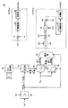
図1は、本発明の実施の形態に従う電源システム1を備える車両100の要部を示す概略構成図である。
FIG. 1 is a schematic configuration diagram showing a main part of a
図1を参照して、本実施の形態においては、負荷装置の一例として、車両100の駆動力を発生するための駆動力発生部3との間で電力授受を行なう構成について例示する。そして、車両100は、駆動力発生部3が電源システム1から供給される電力を受けて発生する駆動力を車輪(図示しない)に伝達することで走行する。
With reference to FIG. 1, in the present embodiment, as an example of a load device, a configuration in which power is transferred to and from drive
本実施の形態においては、複数の蓄電部の一例として、2つの蓄電部を有する電源システム1について説明する。電源システム1は、主正母線MPLおよび主負母線MNLを介して、駆動力発生部3との間で直流電力の授受を行なう。
In the present embodiment,
駆動力発生部3は、第1インバータINV1と、第2インバータINV2と、第1モータジェネレータMG1と、第2モータジェネレータMG2とを備え、HV_ECU(Hybrid Vehicle Electrical Control Unit)4からのスイッチング指令PWM1,PWM2に応じて駆動力を発生する。
The driving
インバータINV1,INV2は、主正母線MPLおよび主負母線MNLに並列接続され、それぞれ電源システム1との間で電力の授受を行なう。すなわち、インバータINV1,INV2は、それぞれ主正母線MPLおよび主負母線MNLを介して受ける直流電力を交流電力に変換してモータジェネレータMG1,MG2へ供給する。さらに、インバータINV1,INV2は、車両100の回生制動時などにおいて、モータジェネレータMG1,MG2が車両100の運動エネルギーを受けて発電する交流電力を直流電力に変換して回生電力として電源システム1へ返還する。一例として、インバータINV1,INV2は、三相分のスイッチング素子を含むブリッジ回路で構成され、それぞれHV_ECU4から受けたスイッチング指令PWM1,PWM2に応じて、スイッチング(回路開閉)動作を行なうことで、三相交流電力を発生する。
Inverters INV1 and INV2 are connected in parallel to main positive bus MPL and main negative bus MNL, and exchange power with
モータジェネレータMG1,MG2は、それぞれインバータINV1,INV2から供給される交流電力を受けて回転駆動力を発生可能であるとともに、外部からの回転駆動力を受けて交流電力を発電可能に構成される。一例として、モータジェネレータMG1,MG2は、永久磁石が埋設されたロータを備える三相交流回転電機である。そして、モータジェネレータMG1,MG2は、それぞれ動力伝達機構6と連結され、発生した駆動力を駆動軸8によって車輪(図示しない)へ伝達する。 Motor generators MG1 and MG2 are configured to receive AC power supplied from inverters INV1 and INV2, respectively, to generate rotational driving force, and to generate AC power by receiving external rotational driving force. As an example, motor generators MG1 and MG2 are three-phase AC rotating electric machines including a rotor in which permanent magnets are embedded. Motor generators MG1 and MG2 are connected to power transmission mechanism 6 and transmit the generated driving force to wheels (not shown) by drive shaft 8.
なお、駆動力発生部3がハイブリッド車両に適用される場合には、モータジェネレータMG1,MG2は、動力伝達機構6または駆動軸8を介してエンジン(図示しない)とも機械的に連結される。そして、HV_ECU4によって、エンジンの発生する駆動力とモータジェネレータMG1,MG2の発生する駆動力とが最適な比率となるように制御が実行される。このようなハイブリッド車両に適用される場合には、一方のモータジェネレータをもっぱら電動機として機能させ、他方のモータジェネレータをもっぱら発電機として機能させるように構成することもできる。
When driving
HV_ECU4は、予め格納されたプログラムを実行することで、図示しない各センサから送信された信号、走行状況、アクセル開度の変化率、および格納しているマップなどに基づいて、モータジェネレータMG1,MG2の目標トルクおよび目標回転数を算出する。そして、HV_ECU4は、モータジェネレータMG1,MG2の発生トルクおよび回転数がそれぞれ当該算出した目標トルクおよび目標回転数となるように、スイッチング指令PWM1,PWM2を生成して駆動力発生部3へ与える。
The HV_ECU 4 executes a program stored in advance, so that the motor generators MG1, MG2 are based on a signal transmitted from each sensor (not shown), a traveling state, a change rate of the accelerator opening, a stored map, and the like. Target torque and target rotation speed are calculated. Then, HV_ECU 4 generates switching commands PWM1 and PWM2 and supplies them to driving
また、HV_ECU4は、当該算出した目標トルクおよび目標回転数、もしくは図示しない各種センサにより検出したトルク実績値および回転数実績値に基づいて、モータジェネレータMG1,MG2のそれぞれにおいて生じる逆起電圧Vm1,Vm2を取得し、当該逆起電圧Vm1,Vm2に基づいて決定される電圧要求値Vh*を電源システム1へ出力する。すなわち、駆動力発生部3が力行動作を行なう場合には、電源システム1からモータジェネレータMG1,MG2へ電力を供給できるように、HV_ECU4は、逆起電圧Vm1,Vm2より大きい電圧を電圧要求値Vh*として決定する。一方、駆動力発生部3が回生動作を行なう場合には、モータジェネレータMG1,MG2が発生する電力が電源システム1へ逆流できるように、HV_ECU4は、逆起電圧Vm1,Vm2より小さい電圧を電圧要求値Vh*として決定する。
Further, HV_ECU 4 generates counter electromotive voltages Vm1, Vm2 generated in motor generators MG1, MG2 based on the calculated target torque and target rotational speed, or actual torque value and actual rotational speed value detected by various sensors (not shown). And a voltage requirement value Vh * determined based on the counter electromotive voltages Vm1 and Vm2 is output to the
さらに、HV_ECU4は、上述の目標トルクと目標回転数との積、もしくはトルク実績値と回転数実績値との積に基づいて、電力要求値PL *を算出して電源システム1へ出力する。なお、HV_ECU4は、電力要求値PL *の符号を変化させることで、力行動作(正値)および回生動作(負値)といった駆動力発生部3における電力要求を電源システム1へ伝送する。
Further, the HV_ECU 4 calculates a power request value P L * based on the product of the target torque and the target rotation speed, or the product of the actual torque value and the actual rotation speed value, and outputs it to the
一方、電源システム1は、平滑コンデンサCと、供給電流検出部16と、供給電圧検出部18と、第1のコンバータCONV1と、第2のコンバータCONV2と、第1の蓄電部BAT1と、第2の蓄電部BAT2と、電池電流検出部10−1,10−2と、電池電圧検出部12−1,12−2と、電池温度検出部14−1,14−2と、制御部2とを備える。
On the other hand, the
平滑コンデンサCは、主正母線MPLと主負母線MNLとの間に接続され、コンバータCONV1,CONV2からの供給電力に含まれる変動成分(交流成分)を低減する。 Smoothing capacitor C is connected between main positive bus MPL and main negative bus MNL, and reduces fluctuation components (AC components) included in the power supplied from converters CONV1 and CONV2.
供給電流検出部16は、主正母線MPLに直列に介挿され、駆動力発生部3への供給電流Ihを検出し、その検出結果を制御部2へ出力する。
Supply
供給電圧検出部18は、主正母線MPLと主負母線MNLとの間に接続され、駆動力発生部3への供給電圧Vhを検出し、その検出結果を制御部2へ出力する。
The
コンバータCONV1,CONV2は、それぞれ対応の蓄電部BAT1,BAT2の充電/放電を制御可能に構成される。すなわち、コンバータCONV1,CONV2は、それぞれ対応の蓄電部BAT1,BAT2と主正母線MPLおよび主負母線MNLとの間で電圧変換動作(降圧動作/昇圧動作)を行なうことで、蓄電部BAT1,BAT2の充電/放電を制御する。具体的には、蓄電部BAT1,BAT2を充電する場合には、コンバータCONV1,CONV2は、それぞれ主正母線MPLと主負母線MNLとの間の電圧を降圧して、充電電流を蓄電部BAT1,BAT2へ供給する。一方、蓄電部BAT1,BAT2を放電する場合には、コンバータCONV1,CONV2は、それぞれ蓄電部BAT1,BAT2の電池電圧を昇圧して、主正母線MPLおよび主負母線MNLを介して放電電流を供給する。 Converters CONV1 and CONV2 are configured to be able to control charging / discharging of corresponding power storage units BAT1 and BAT2, respectively. In other words, converters CONV1 and CONV2 perform voltage conversion operations (step-down operation / step-up operation) between corresponding power storage units BAT1 and BAT2 and main positive bus MPL and main negative bus MNL, respectively, so that power storage units BAT1 and BAT2 Control charging / discharging of Specifically, when charging power storage units BAT1 and BAT2, converters CONV1 and CONV2 step down the voltage between main positive bus MPL and main negative bus MNL, and charge current is stored in power storage units BAT1 and BAT1, respectively. Supply to BAT2. On the other hand, when discharging power storage units BAT1 and BAT2, converters CONV1 and CONV2 boost the battery voltages of power storage units BAT1 and BAT2, respectively, and supply a discharge current via main positive bus MPL and main negative bus MNL. To do.
蓄電部BAT1,BAT2は、それぞれコンバータCONV1,CONV2による充放電が可能に構成される。後述するように、本発明の実施の形態に従う電源システムでは、蓄電部BAT1,BAT2のうち、いずれか一方が温度管理対象となる。この温度管理対象は、予め固定しておくこともできるし、蓄電部BAT1,BAT2の蓄電状態(SOC:State of Charge)や電池温度などに応じて随時切換ることもできる。 Power storage units BAT1, BAT2 are configured to be chargeable / discharged by converters CONV1, CONV2, respectively. As will be described later, in the power supply system according to the embodiment of the present invention, one of power storage units BAT1, BAT2 is a temperature management target. This temperature management target can be fixed in advance, or can be switched at any time according to the state of charge (SOC) of the power storage units BAT1 and BAT2, the battery temperature, and the like.
このように温度管理対象となり得る蓄電部は、蓄電状態に応じて、充電および放電のそれぞれに伴う熱反応が発熱反応および吸熱反応のいずれとなるかが変化する熱反応特性を有する化学電池を含んで構成される。このような化学電池の一例として、リチウムイオン電池が用いられる。このような化学電池の熱反応特性の詳細は後述する。 As described above, the power storage unit that can be a temperature management target includes a chemical battery having a thermal reaction characteristic that changes whether a thermal reaction associated with charging and discharging is an exothermic reaction or an endothermic reaction, depending on a storage state. Consists of. As an example of such a chemical battery, a lithium ion battery is used. Details of the thermal reaction characteristics of such a chemical battery will be described later.
以下の説明においては、一例として、蓄電部BAT1が温度管理対象である場合について説明する。なお、蓄電部BAT1が固定的に温度管理対象である場合には、蓄電部BAT2は必ずしも上述のような化学電池で構成される必要はなく、電気二重層キャパシタなどの蓄電素子を用いてもよい。 In the following description, a case where the power storage unit BAT1 is a temperature management target will be described as an example. In the case where the power storage unit BAT1 is fixedly temperature controlled, the power storage unit BAT2 does not necessarily need to be configured by the chemical battery as described above, and a power storage element such as an electric double layer capacitor may be used. .
電池電流検出部10−1,10−2は、それぞれ蓄電部BAT1,BAT2とコンバータCONV1,CONV2とを接続する2本の電力線の一方に介挿され、蓄電部BAT1,BAT2の入出力に係る電池電流Ib1,Ib2を検出し、その検出結果を制御部2へ出力する。
Battery current detection units 10-1 and 10-2 are inserted into one of two power lines connecting power storage units BAT1 and BAT2 and converters CONV1 and CONV2, respectively, and batteries relating to input / output of power storage units BAT1 and BAT2 The currents Ib1 and Ib2 are detected, and the detection results are output to the
電池電圧検出部12−1,12−2は、それぞれ蓄電部BAT1,BAT2とコンバータCONV1,CONV2とを接続する2本の電力線の線間に接続され、蓄電部BAT1,BAT2の電池電圧Vb1,Vb2を検出し、その検出結果を制御部2へ出力する。
Battery voltage detection units 12-1 and 12-2 are connected between two power lines connecting power storage units BAT1 and BAT2 and converters CONV1 and CONV2, respectively, and battery voltages Vb1 and Vb2 of power storage units BAT1 and BAT2 are connected. And the detection result is output to the
電池温度検出部14−1,14−2は、それぞれ蓄電部BAT1,BAT2を構成する電池セルなどに近接して配置され、蓄電部BAT1,BAT2の内部温度である電池温度Tb1,Tb2を検出し、その検出結果を制御部2へ出力する。なお、電池温度検出部14−1,14−2は、それぞれ蓄電部BAT1,BAT2を構成する複数の電池セルに対応付けて配置された複数の検出素子の検出結果に基づいて、平均化処理などにより代表値を出力するように構成されてもよい。
Battery temperature detection units 14-1 and 14-2 are arranged in proximity to the battery cells and the like constituting power storage units BAT1 and BAT2, respectively, and detect battery temperatures Tb1 and Tb2 that are internal temperatures of power storage units BAT1 and BAT2. The detection result is output to the
制御部2は、電圧要求値Vh*および電力要求値PL *と、供給電流Ihと、供給電圧Vhと、電池電流Ib1,Ib2と、電池電圧Vb1,Vb2と、電池温度Tb1,Tb2とに基づいて、後述する制御構造に従ってそれぞれスイッチング指令PWC1,PWC2を生成し、コンバータCONV1,CONV2における電圧変換動作を制御する。
特に、制御部2は、電池温度検出部14−1から温度管理対象の蓄電部BAT1の電池温度Tb1および蓄電状態(SOC)を取得し、取得した電池温度Tb1に基づいて、蓄電部BAT1の昇温要求または冷却要求を生成する。蓄電部BAT1に昇温要求または冷却要求が発生されると、制御部2は、取得した蓄電状態から、蓄電部BAT1の熱反応特性に基づいて、昇温要求または冷却要求を満たすために、蓄電部BAT1について充電側および放電側のいずれの方向に電流を流すべきかを決定する。さらに、制御部2は、蓄電部BAT1に決定した方向の電流を流すためのスイッチング指令PWC1を生成し、コンバータCONV1に与える。
In particular, the
このように、制御部2は、電池温度Tb1に応じて、蓄電部BAT1に流す電流の方向を切換ることで、蓄電部BAT1の温度管理を行なう。
Thus,
また、制御部2は、蓄電部BAT1の電池温度Tb1に基づいて、温度管理を行なうために蓄電部BAT1に流す電流の目標電流値を決定する。具体的には、制御部2は、蓄電部BAT1に流れる電池電流Ib1と抵抗性の発熱量との対応を示す抵抗発熱特性を参照して、目標電流値を決定する。すなわち、制御部2は、電池電流に起因する抵抗性の発熱量が過大とならないように、目標電流値を決定する。
さらに、制御部2は、昇温要求が生成されたときには、蓄電部BAT1の電池電流Ib1と蓄電部BAT1の電池電圧Vb1との対応を示す出力電圧特性に基づいて、目標電流値を制限してもよい。すなわち、制御部2は、蓄電部BAT1の電池電圧Vb1を所定電圧値以上に維持するために、蓄電部BAT1からの放電電流を所定の範囲に制限する。
Further, when the temperature increase request is generated,
一方、制御部2は、蓄電部BAT1の充放電電力と電力要求値PL *との差に相当する電力を供給させるためのスイッチング指令PWC2を生成し、コンバータCONV2に与える。すなわち、制御部2は、昇温要求または冷却要求を満たすために電源システム1内を流れる電流の影響が電源システム1の外部(駆動力発生部3)へ波及しないように、コンバータCONV2および蓄電部BAT2の充電/放電を制御する。
On the other hand,
本発明の実施の形態においては、駆動力発生部3が「負荷装置」に相当し、主正母線MPLおよび主負母線MNLが「電力線」に相当し、コンバータCONV1,CONV2が「複数の充放電制御部」に相当する。また、制御部2が「温度取得手段」、「蓄電状態取得手段」、「要求生成手段」、「電流方向決定手段」、「制御指令生成手段」、「目標電流値決定手段」、および「電流値制限手段」を実現する。
In the embodiment of the present invention, the driving
図2は、本発明の実施の形態に従うコンバータCONV1,CONV2の概略構成図である。 FIG. 2 is a schematic configuration diagram of converters CONV1 and CONV2 according to the embodiment of the present invention.
図2を参照して、コンバータCONV1は、一例として、双方型のチョッパ回路を含んで構成され、チョッパ回路40Aと、平滑コンデンサC1とからなる。
Referring to FIG. 2, converter CONV1 includes, for example, a both-type chopper circuit, and includes
チョッパ回路40Aは、電力を双方向に供給することが可能である。具体的には、チョッパ回路40Aは、制御部2(図1)からのスイッチング指令PWC1に応じて、蓄電部BAT1からの放電電流を昇圧して駆動力発生部3(図1)へ供給可能であるとともに、駆動力発生部3から受けた回生電力を降圧して蓄電部BAT1へ充電電流として供給可能である。そして、チョッパ回路40Aは、それぞれ正母線LN1Aと、負母線LN1Cと、配線LN1Bと、スイッチング素子であるトランジスタQ1A,Q1Bと、ダイオードD1A,D1Bと、インダクタL1とを含む。
The
正母線LN1Aは、その一方端がトランジスタQ1Aのコレクタに接続され、他方端が主正母線MPLに接続される。また、負母線LN1Cは、その一方端が蓄電部BAT1の負側に接続され、他方端が主負母線MNLに接続される。 Positive bus LN1A has one end connected to the collector of transistor Q1A and the other end connected to main positive bus MPL. Negative bus LN1C has one end connected to the negative side of power storage unit BAT1 and the other end connected to main negative bus MNL.
トランジスタQ1AおよびQ1Bは、正母線LN1Aと負母線LN1Cとの間に直列に接続される。そして、トランジスタQ1Aのコレクタは正母線LN1Aに接続され、トランジスタQ1Bのエミッタは負母線LN1Cに接続される。また、各トランジスタQ1A,Q1Bのコレクタ−エミッタ間には、エミッタ側からコレクタ側へ電流を流すダイオードD1A,D1Bがそれぞれ接続されている。さらに、インダクタL1は、トランジスタQ1AとトランジスタQ1Bとの接続点に接続される。 Transistors Q1A and Q1B are connected in series between positive bus LN1A and negative bus LN1C. Transistor Q1A has a collector connected to positive bus LN1A, and transistor Q1B has an emitter connected to negative bus LN1C. Further, diodes D1A and D1B that flow current from the emitter side to the collector side are connected between the collector and emitter of the transistors Q1A and Q1B, respectively. Further, inductor L1 is connected to a connection point between transistor Q1A and transistor Q1B.
配線LN1Bは、一方端が蓄電部BAT1の正側に接続され、他方端がインダクタL1に接続される。 Line LN1B has one end connected to the positive side of power storage unit BAT1, and the other end connected to inductor L1.
平滑コンデンサC1は、配線LN1Bと負母線LN1Cとの間に接続され、配線LN1Bと負母線LN1Cとの間の直流電圧に含まれる交流成分を低減する。 Smoothing capacitor C1 is connected between wiring LN1B and negative bus LN1C, and reduces the AC component included in the DC voltage between wiring LN1B and negative bus LN1C.
コンバータCONV2についても上述したコンバータCONV1と同様の構成および動作であるので、詳細な説明は繰返さない。 Since converter CONV2 has the same configuration and operation as converter CONV1 described above, detailed description thereof will not be repeated.
(化学電池の熱反応特性)
化学電池は、化学反応を利用して電気エネルギーを蓄えるので、充電/放電の進行に伴って内部部材のエントロピーが変化する。このエントロピーの変化に起因して、化学電池では発熱反応または吸熱反応が生じる。なお、多くの化学電池において、このような現象が生じ得るが、比較的その効果が大きいものとして、上述のリチウムイオン電池が挙げられる。
(Thermal reaction characteristics of chemical batteries)
Since the chemical battery stores electric energy using a chemical reaction, the entropy of the internal member changes with the progress of charging / discharging. Due to this change in entropy, an exothermic or endothermic reaction occurs in a chemical battery. Such a phenomenon can occur in many chemical batteries, but the lithium ion battery described above can be cited as one that has a relatively large effect.
図3は、本発明に係る化学電池の蓄電状態(SOC)と熱反応との対応を示す熱反応特性の一例を示す図である。 FIG. 3 is a diagram illustrating an example of a thermal reaction characteristic indicating a correspondence between a storage state (SOC) of the chemical battery according to the present invention and a thermal reaction.
図3を参照して、本発明に係る化学電池では、蓄電状態に応じて、充電および放電のそれぞれに伴う熱反応が発熱反応および吸熱反応のいずれとなるかが変化することがわかる。図3に示す例においては、状態値S1およびS3において、充電/放電に伴って生じる熱反応が互いに入れ替わる。 Referring to FIG. 3, it can be seen that in the chemical battery according to the present invention, whether the thermal reaction accompanying charging and discharging is an exothermic reaction or an endothermic reaction changes depending on the state of charge. In the example shown in FIG. 3, in the state values S1 and S3, the thermal reactions that occur with charging / discharging are interchanged.
すなわち、蓄電状態が状態値S1より小さい場合、および蓄電状態が状態値S3より大きい場合には、放電側に電流を流すことで発熱反応が生じる一方、充電側に電流を流すことで吸熱反応が生じる。また、蓄電状態が状態値S1と状態値S3との間である場合には、充電側に電流を流すことで発熱反応が生じる一方、放電側に電流を流すことで吸熱反応が生じる。 That is, when the state of charge is smaller than the state value S1 and when the state of charge is larger than the state value S3, an exothermic reaction occurs when current flows on the discharge side, while an endothermic reaction occurs when current flows on the charge side. Arise. Further, when the storage state is between the state value S1 and the state value S3, an exothermic reaction occurs when current is supplied to the charging side, while an endothermic reaction occurs when current is supplied to the discharging side.
このようなエントロピー変化に係る熱反応は、蓄電状態の変化量に応じてその発熱量および吸熱量が定まる。すなわち、図3に示す熱反応特性において、実際に発生する熱量(発熱量または吸熱量)は、蓄電状態が変化した区間の積分値(面積)に相当する。そのため、発生する熱量は、電池電流の大きさとは相関が無く、実際に変化した蓄電状態の状態差に依存して定まる。このように、蓄電部の蓄電状態に応じて、正しい電流方向(充電側または放電側)を決定するだけで、蓄電部の昇温要求および冷却要求をいずれも満足させることができ、必ずしもその電流値まで決定する必要はない。 The heat reaction related to such an entropy change has its calorific value and endothermic amount determined according to the amount of change in the storage state. That is, in the thermal reaction characteristic shown in FIG. 3, the amount of heat actually generated (a calorific value or an endothermic amount) corresponds to an integral value (area) of a section where the state of charge has changed. For this reason, the amount of generated heat has no correlation with the magnitude of the battery current, and is determined depending on the state difference of the actually changed storage state. Thus, by determining the correct current direction (charging side or discharging side) according to the power storage state of the power storage unit, both the temperature increase request and the cooling request of the power storage unit can be satisfied, and the current There is no need to determine the value.
具体的には、昇温要求を満足させるためには、蓄電状態が状態値S1より小さければ、もしくは蓄電状態が状態値S3より大きければ、放電側に電流を流せばよく、また、蓄電状態が状態値S1より大きく、かつ状態値S3より小さければ、充電側に電流を流せばよい。一方で、冷却要求を満足させるためには、蓄電状態が状態値S1より小さければ、もしくは蓄電状態が状態値S3より大きければ、充電側に電流を流せばよく、また、蓄電状態が状態値S1より大きく、かつ状態値S3より小さければ、放電側に電流を流せばよい。 Specifically, in order to satisfy the temperature increase request, if the state of charge is smaller than the state value S1 or the state of charge is larger than the state value S3, a current may be passed to the discharge side. If it is larger than the state value S1 and smaller than the state value S3, a current may be supplied to the charging side. On the other hand, in order to satisfy the cooling request, if the power storage state is smaller than the state value S1 or the power storage state is larger than the state value S3, a current may be passed to the charging side, and the power storage state may be the state value S1. If it is larger and smaller than the state value S3, a current may be supplied to the discharge side.
なお、蓄電部の蓄電状態(SOC)を測定する方法としては、周知のさまざまな手段を用いることができるが、一例として、蓄電部が開回路状態で生じる電池電圧(開回路電圧値)から算出される暫定SOCと、電池電流の積算値から算出される補正SOCとを加算することで蓄電状態を逐次的に検出できる。 In addition, as a method for measuring the storage state (SOC) of the power storage unit, various well-known means can be used. As an example, calculation is performed from a battery voltage (open circuit voltage value) generated when the power storage unit is in an open circuit state. By adding the provisional SOC and the corrected SOC calculated from the integrated value of the battery current, the state of charge can be detected sequentially.
(昇温動作および冷却動作)
図4は、図3に示す熱反応特性を有する蓄電部BAT1に対する昇温動作および冷却動作の概略について説明するための図である。なお、図4においては、蓄電部BAT1の蓄電状態が図3における状態値S2(状態値S1<状態値S2<状態値S3)である場合を示する。
(Temperature raising operation and cooling operation)
FIG. 4 is a diagram for explaining the outline of the temperature raising operation and the cooling operation for power storage unit BAT1 having the thermal reaction characteristics shown in FIG. FIG. 4 shows a case where the power storage state of power storage unit BAT1 is state value S2 in FIG. 3 (state value S1 <state value S2 <state value S3).
図4(a)は、蓄電部BAT1を昇温動作させる場合を示す図である。
図4(b)は、蓄電部BAT1を冷却動作させる場合を示す図である。
FIG. 4 (a) is a diagram illustrating a case where the power storage unit BAT1 is operated to increase in temperature.
FIG. 4B is a diagram illustrating a case where the power storage unit BAT1 is cooled.
図3および図4(a)を参照して、蓄電部BAT1の蓄電状態が図3に示す状態値S2である場合には、蓄電部BAT1に充電側の電流を流すことで、昇温動作を行なうことができる。そこで、図4に示すように、コンバータCONV1から蓄電部BAT1に向けて電池電流Ib1が供給される。 Referring to FIG. 3 and FIG. 4 (a), when the power storage state of power storage unit BAT1 is state value S2 shown in FIG. 3, the temperature rising operation is performed by passing a current on the charging side to power storage unit BAT1. Can be done. Therefore, as shown in FIG. 4, battery current Ib1 is supplied from converter CONV1 toward power storage unit BAT1.
一方、電源システム1全体としては、駆動力発生部3からの要求電力L *に応じた電力PLを駆動力発生部3へ供給する必要がある。そのため、コンバータCONV2は、コンバータCONV1から蓄電部BAT1へ供給される電池電流Ib1に相当する電力P1を補償しつつ、要求電力L *に応じた電力PLが供給されるように制御される。すなわち、蓄電部BAT2は、要求電力L *に電力P1を加算(負値の減算)した電力に相当する電池電流Ib2を放電することになる。
Meanwhile,
また、図3および図4(b)を参照して、蓄電部BAT1の蓄電状態が図3に示す状態値S2である場合には、蓄電部BAT1に放電側の電流を流すことで、冷却動作を行なうことができる。そこで、図4に示すように、蓄電部BAT1からコンバータCONV1に向けて電池電流Ib1が供給される。 3 and 4B, when the power storage state of power storage unit BAT1 is state value S2 shown in FIG. 3, the cooling operation is performed by passing a discharge-side current to power storage unit BAT1. Can be performed. Therefore, as shown in FIG. 4, battery current Ib1 is supplied from power storage unit BAT1 to converter CONV1.
上述したように、電源システム1全体としては、駆動力発生部3からの要求電力L *に応じた電力PLを駆動力発生部3へ供給する必要がある。そのため、蓄電部BAT2は、要求電力L *から電力P1を減算した電力に相当する電池電流Ib2を放電することになる。当然のことながら、蓄電部BAT1から放電される電力P1が要求電力L *より大きければ、蓄電部BAT2は、電力P1と要求電力L *との差電力で充電される。
As described above,
図4(a)および図4(b)に示すコンバータCONV1,CONV2の電流制御動作はさまざまな方法で実現可能であるが、本発明の実施の形態においては、後述するように、コンバータCONV1を電流制御モードで制御する一方、コンバータCONV2を電圧制御モードで制御する。 The current control operations of converters CONV1 and CONV2 shown in FIGS. 4A and 4B can be realized by various methods. In the embodiment of the present invention, as will be described later, converter CONV1 is supplied with current. While controlling in the control mode, the converter CONV2 is controlled in the voltage control mode.
(目標電流値の決定)
上述したように、本発明においては、化学電池のエントロピー変化に係る熱反応を利用することで蓄電部の温度管理を実現する。しかしながら、化学電池を含んで構成される蓄電部では、エントロピー変化に係る熱反応に加えて、電池電流に起因する抵抗性の発熱も存在する。そのため、特に冷却動作時には、電池電流に起因する抵抗性の発熱量が過大とならないように、目標電流値が決定される。
(Determination of target current value)
As described above, in the present invention, the temperature management of the power storage unit is realized by using the thermal reaction related to the entropy change of the chemical battery. However, in a power storage unit configured to include a chemical battery, in addition to the thermal reaction related to the entropy change, there is also resistive heat generation due to the battery current. Therefore, particularly during the cooling operation, the target current value is determined so that the resistive heat generation amount due to the battery current does not become excessive.
図5は、蓄電部BAT1に流れる電池電流Ib1と抵抗性の発熱量との対応を示す抵抗発熱特性の一例を示す図である。 FIG. 5 is a diagram illustrating an example of resistance heat generation characteristics indicating the correspondence between the battery current Ib1 flowing through the power storage unit BAT1 and the resistance heat generation amount.
図5を参照して、電池電流Ib1による抵抗性の発熱は、蓄電部BAT1の分極作用などに起因する内部抵抗により生じる。この分極作用は、蓄電部BAT1が低温であるほどその効果が大きくなるため、電池温度Tb1が小さいほど、内部抵抗は大きくなる。したがって、電池電流Ib1が大きいほど、かつ、電池温度Tb1が小さいほど、蓄電部BAT1における抵抗性の発熱量は増大する。なお、抵抗性の発熱量は、電池電流Ib1の絶対値に依存するので、その流れる方向(充電側または放電側)には依存しない。 Referring to FIG. 5, resistive heat generation due to battery current Ib <b> 1 is caused by internal resistance caused by the polarization action of power storage unit BAT <b> 1. Since the effect of this polarization action increases as the temperature of the power storage unit BAT1 decreases, the internal resistance increases as the battery temperature Tb1 decreases. Therefore, as the battery current Ib1 is larger and the battery temperature Tb1 is smaller, the resistive heat generation amount in the power storage unit BAT1 increases. Note that the amount of heat generated by the resistance depends on the absolute value of the battery current Ib1, and therefore does not depend on the flowing direction (charging side or discharging side).
したがって、制御部2は、蓄電部BAT1の電池温度Tb1に基づいて、電池電流Ib1と抵抗性の発熱量との対応を示す抵抗発熱特性を参照することで、温度管理を行なうために流される電池電流Ib1についての目標電流値が決定される。
Therefore, the
特に、冷却動作時などにおいては、抵抗性の発熱量がエントロピー変化に係る熱反応による吸熱量を上回らないように、電池電流Ib1の目標電流値が決定される。 In particular, during a cooling operation or the like, the target current value of the battery current Ib1 is determined so that the resistive heat generation amount does not exceed the heat absorption amount due to the thermal reaction related to the entropy change.
(制御構造)
図6は、本発明の実施の形態に従う制御部2における制御構造を示すブロック図である。
(Control structure)
FIG. 6 is a block diagram showing a control structure in
図6を参照して、本発明の実施の形態に従う制御構造は、蓄電部BAT1,BAT2が所望の充放電を行なうように、コンバータCONV1,CONV2における充放電制御動作を指示するためのスイッチング指令PWC1,PWC2を生成する。そして、本発明の実施の形態に従う制御構造は、要求生成部50と、蓄電状態(SOC)算出部52と、電流方向決定部54と、目標電流値決定部56と、電流値制限部58と、選択部60と、電流制御部ICTRL1と、電圧制御部VCTRL1とを含む。
Referring to FIG. 6, the control structure according to the embodiment of the present invention includes a switching command PWC1 for instructing a charge / discharge control operation in converters CONV1, CONV2 so that power storage units BAT1, BAT2 perform desired charge / discharge. , PWC2 is generated. The control structure according to the embodiment of the present invention includes a
要求生成部50は、蓄電部BAT1の電池温度Tb1に基づいて、蓄電部BAT1における昇温要求または冷却要求の有無を判断し、その判断結果を電流方向決定部54、電流値制限部58および選択部60へ出力する。具体的には、要求生成部50は、蓄電部BAT1の電池温度Tb1と、予め定められる温度管理値Tb1*とを比較し、両者の間に所定のしきい値温度以上の偏差が生じていれば、昇温要求または冷却要求を生成する。
Based on battery temperature Tb1 of power storage unit BAT1,
蓄電状態算出部52は、それぞれ電池温度検出部14−1、電池電流検出部10−1および電池電圧検出部12−1から取得した電池温度Tb1、電池電流Ib1および電池電圧Vb1に基づいて、蓄電部BAT1の蓄電状態(SOC)を算出する。一例として、蓄電状態算出部52は、電池温度Tb1における、予め実験的に取得された蓄電状態と開回路電圧値との対応を示す開回路電圧特性に基づいて、電池電流Ib1と電池電圧Vb1とにより導出される開回路電圧値から暫定SOCを算出する。また、蓄電状態算出部52は、電池電流Ib1の積算値から補正SOCを算出する。そして、蓄電状態算出部52は、暫定SOCと補正SOCとを加算して、蓄電状態(SOC)を逐次的に算出する。
The storage
電流方向決定部54は、蓄電部BAT1の蓄電状態と熱反応との対応を示す熱反応特性に基づいて、要求生成部50からの昇温要求または冷却要求を満たすために、充電側および放電側のいずれの方向に電流を流すべきかを決定する。具体的には、電流方向決定部54は、蓄電状態算出部52から蓄電部BAT1の蓄電状態を取得し、予め試験的に得られた熱反応特性において、取得した蓄電状態に対応する熱反応が吸熱反応および発熱反応のいずれであるかを判断する。そして、電流方向決定部54は、その判断結果を目標電流値決定部56へ出力する。
Based on the thermal reaction characteristic indicating the correspondence between the storage state of the power storage unit BAT1 and the thermal reaction, the current
目標電流値決定部56は、蓄電部BAT1の電池温度Tb1に基づいて、電流方向決定部54によって決定される充電/放電に伴う目標電流値Ib1*を決定する。すなわち、目標電流値決定部56は、エントロピー変化に係る熱反応による吸発熱量と、抵抗性の発熱量との関係に基づいて、目標電流値Ib1*を決定する。具体的には、目標電流値決定部56は、蓄電部BAT1に流れる電池電流Ib1と発熱量との対応を示す予め定められた抵抗発熱特性を参照して、昇温時には所定の抵抗性の発熱量が生じるように目標電流値Ib1*を決定し、冷却時には、抵抗性の発熱量がエントロピー変化に係る熱反応による吸熱量を超過しないように、目標電流値Ib1*を決定する。なお、蓄電部BAT1に対して充電側または放電側のいずれの方向に電流を流すべきかを特定するために、目標電流値決定部56は、充電側を負値(−値)とし、放電側を正値(+値)とするように、目標電流値Ib1*を出力する。そして、目標電流値決定部56は、冷却時の目標電流値Ib1*を選択部60へ出力する一方、昇温時の目標電流値Ib1*を電流値制限部58へ出力する。
Target current value determining unit 56 determines target current value Ib1 * associated with charging / discharging determined by current
電流値制限部58は、要求生成部50によって昇温要求が生じていると判断されたときに、蓄電部BAT1の放電電流と蓄電部BAT1の電池電圧Vb1との対応を示す予め定められた出力電圧特性に基づいて、目標電流値決定部56によって決定される目標電流値Ib1*を制限する。すなわち、昇温時には、目標電流値決定部56は、可能な限り大きな電流を流すように目標電流値Ib1*を決定するが、蓄電部BAT1の放電電流が大きくなり過ぎると、内部抵抗に伴う電圧降下によって出力電圧が過剰に低下するおそれがある。そこで、電流値制限部58は、蓄電部BAT1の出力電圧を所定の下限値以上に維持するように、昇温時の目標電流値Ib1*を制限する。
Current
一般的に、蓄電部の内部抵抗は、電池温度に依存して変化する。そのため、電流値制限部58は、電池温度毎に予め試験的に求められた複数の出力電圧特性の中から、蓄電部BAT1の電池温度Tb1に応じた出力電圧特性を選択し、当該選択した出力電圧特定に基づいて、昇温時の目標電流値Ib1*が所定の上限値を超過しないように制限する。電流値制限部58は、制限後の目標電流値#Ib1*を選択部60へ出力する。
Generally, the internal resistance of the power storage unit varies depending on the battery temperature. Therefore, current
選択部60は、要求生成部50から受けた判断結果に応じて、目標電流値決定部56から受けた冷却時の目標電流値Ib1*、および電流値制限部58から受けた昇温時の目標電流値#Ib1*のいずれか一方を電流制御部ICTRL1へ出力する。
In accordance with the determination result received from
電流制御部ICTRL1は、蓄電部BAT1の電池電流Ib1が選択部60から出力される目標電流値と一致するように、スイッチング指令PWC1を生成する。具体的には、電流制御部ICTRL1は、減算部62と、PI制御部64と、変調部66とを含む。ここで、減算部62とPI制御部64とは、電流フィードバック制御要素を構成する。
Current control unit ICTRL1 generates switching command PWC1 such that battery current Ib1 of power storage unit BAT1 matches the target current value output from
減算部62は、選択部60から出力される目標電流値と、蓄電部BAT1の電池電流Ib1との偏差を算出し、その算出した偏差をPI制御部64へ出力する。
PI制御部64は、少なくとも比例要素(P:proportional element)および積分要素(I:integral element)を含んで構成され、減算部62から出力される偏差に応じた制御出力を所定のゲインおよび時定数に従って出力する。
The
変調部66は、図示しない発振部が発生する搬送波(キャリア波)とPI制御部64からの制御出力とを比較して、スイッチング指令PWC1を生成する。なお、PI制御部64から出力される制御出力は、コンバータCONV1のトランジスタQ1AまたはQ1B(図2)に対するデューティー比に相当する。
Modulating
上述のような制御構造によって、コンバータCONV1は、電流制御モード(図4)で動作する。 With the control structure as described above, converter CONV1 operates in the current control mode (FIG. 4).
一方、電圧制御部VCTRL1は、蓄電部BAT1の充放電電力と駆動力発生部3からの電力要求値PL *との差に相当する電力を供給させるために、蓄電部BAT2に対応するコンバータCONV2にスイッチング指令PWC2を与える。すなわち、電圧制御部VCTRL1は、駆動力発生部3への供給電圧Vhが電圧要求値Vh*と一致するように、スイッチング指令PWC2を生成する。ここで、供給電圧Vhは、電源システム1と駆動力発生部3との間の電力授受バランスに応じて定まる。すなわち、駆動力発生部3の電力要求に比較して供給電力が小さければ、供給電圧Vhは低下する。一方、駆動力発生部3の電力要求に比較して供給電力が大きければ、供給電圧Vhは上昇する。したがって、供給電圧Vhを電圧要求値Vh*と一致させるように制御することは、間接的に、蓄電部BAT1の充放電電力と駆動力発生部3からの電力要求値PL *との差に相当する電力を供給させることを意味する。
On the other hand, the converter voltage control unit VCTRL1, in order to supply the power corresponding to the difference between the power demand value P L * from the charge-discharge power and drive
具体的には、電圧制御部VCTRL1は、減算部72と、PI制御部74と、変調部76とを含む。ここで、減算部72とPI制御部74とは、電圧フィードバック制御要素を構成する。
Specifically, the voltage control unit VCTRL1 includes a
減算部72は、駆動力発生部3からの電圧要求値Vh*と、蓄電部BAT2の電池電圧Vb2との偏差を算出し、その算出した偏差をPI制御部74へ出力する。
PI制御部74は、少なくとも比例要素および積分要素を含んで構成され、減算部72から出力される偏差に応じた制御出力を所定のゲインおよび時定数に従って出力する。
The
変調部76は、図示しない発振部が発生する搬送波(キャリア波)とPI制御部74からの制御出力とを比較して、スイッチング指令PWC2を生成する。なお、PI制御部74から出力される制御出力は、コンバータCONV2のトランジスタQ2AまたはQ2B(図2)に対するデューティー比に相当する。
上述のような制御構造によって、コンバータCONV2は、電圧制御モード(図4)で動作する。 With the control structure as described above, converter CONV2 operates in the voltage control mode (FIG. 4).
図7は、本発明の実施の形態に従う制御部2における処理手順を示すフローチャートである。
FIG. 7 is a flowchart showing a processing procedure in
図7を参照して、制御部2は、蓄電部BAT1の電池温度Tb1を取得する(ステップS100)。また、制御部2は、蓄電部BAT1の蓄電状態を取得する(ステップS102)。そして、制御部2は、ステップS100において取得された電池温度Tb1に基づいて、蓄電部BAT1についての昇温要求または冷却要求を生成するか否かを判断する(ステップS104)。
Referring to FIG. 7,
昇温要求が生成された場合(ステップS104において「昇温」の場合)には、制御部2は、ステップS102において取得された蓄電部BAT1の蓄電状態から、蓄電部BAT1の熱反応特性に基づいて、昇温要求を満たすために充電側および放電側のいずれの方向に電流を流すべきかを決定する(ステップS106)。また、制御部2は、ステップS100において取得された蓄電部BAT1の電池温度Tb1に基づいて、蓄電部BAT1の抵抗発熱特性を参照して、充電/放電に伴う蓄電部BAT1についての目標電流値を決定する(ステップS108)。さらに、制御部2は、蓄電部BAT1の出力電圧特性に基づいて、ステップS108において決定される目標電流値を制限する(ステップS110)。
When the temperature increase request is generated (in the case of “temperature increase” in step S104),
そして、制御部2は、蓄電部BAT1の電池電流Ib1がステップS106において決定された方向に流れるように、かつ、その値がステップS108またはS110において決定された目標電流値と一致するように、コンバータCONV1に対するスイッチング指令PWC1を生成する(ステップS112)。
また、制御部2は、供給電圧Vhを電圧要求値Vh*と一致させるように、コンバータCONV2に対するスイッチング指令PWC2を生成する(ステップS114)。そして、制御部2は、最初の処理に戻る。
冷却要求が生成された場合(ステップS104において「冷却」の場合)には、制御部2は、ステップS102において取得された蓄電部BAT1の蓄電状態から、蓄電部BAT1の熱反応特性に基づいて、冷却要求を満たすために充電側および放電側のいずれの方向に電流を流すべきかを決定する(ステップS116)。また、制御部2は、ステップS100において取得された蓄電部BAT1の電池温度Tb1に基づいて、蓄電部BAT1の抵抗発熱特性を参照して、充電/放電に伴う蓄電部BAT1についての目標電流値を決定する(ステップS118)。
When the cooling request is generated (in the case of “cooling” in step S104), the
そして、制御部2は、蓄電部BAT1の電池電流Ib1がステップS116において決定された方向に流れるように、かつ、その値がステップS118において決定された目標電流値と一致するように、コンバータCONV1に対するスイッチング指令PWC1を生成する(ステップS120)。
Then, control
また、制御部2は、供給電圧Vhを電圧要求値Vh*と一致させるように、コンバータCONV2に対するスイッチング指令PWC2を生成する(ステップS114)。そして、制御部2は、最初の処理に戻る。
昇温要求および冷却要求のいずれも生成されない場合(ステップS104においてNOの場合)には、制御部2は、通常の制御モードへ移行する(ステップS122)。そして、制御部2は、最初の処理に戻る。
When neither a temperature increase request nor a cooling request is generated (NO in step S104),
なお、ここで言う「通常の制御モード」としては、特定の制御モードに限定されるものではないが、一例として、コンバータCONV1,CONV2のいずれをも電圧制御モードで制御する構成や、コンバータCONV1,CONV2のいずれをも電流制御モードで制御する構成などが好ましい。 The “normal control mode” referred to here is not limited to a specific control mode. However, as an example, a configuration in which both converters CONV1 and CONV2 are controlled in the voltage control mode, converter CONV1, A configuration in which all of CONV2 are controlled in the current control mode is preferable.
本発明の実施の形態によれば、2つの蓄電部BAT1,BAT2のうち、蓄電部BAT1が温度管理対象にされる。そして、蓄電部BAT1について、昇温要求または冷却要求が生じていると判断されると、熱反応特性に基づいて、蓄電部BAT1に対して充電側および放電側のいずれの方向に電流を流すべきかが決定される。一方、蓄電部BAT2には、温度管理対象ではないので、充放電電流を比較的自由に決定できる。そのため、蓄電部BAT2は、負荷装置の電力要求に応じた充放電制御を行なうことができる。よって、蓄電部BAT1についての温度管理および負荷装置からの電力要求への応答を同時に実現でき、負荷装置との間の授受電力への影響を抑制しつつ、蓄電部の適切な温度管理を実現できる。 According to the embodiment of the present invention, of the two power storage units BAT1 and BAT2, the power storage unit BAT1 is set as a temperature management target. Then, when it is determined that a temperature increase request or a cooling request is generated for power storage unit BAT1, a current should flow to power storage unit BAT1 in either the charge side or the discharge side based on the thermal reaction characteristics Is decided. On the other hand, since the power storage unit BAT2 is not subject to temperature management, the charge / discharge current can be determined relatively freely. Therefore, power storage unit BAT2 can perform charge / discharge control according to the power requirement of the load device. Therefore, the temperature management for the power storage unit BAT1 and the response to the power request from the load device can be realized at the same time, and the appropriate temperature management of the power storage unit can be realized while suppressing the influence on the power exchanged with the load device. .
また、本発明の実施の形態によれば、蓄電部に流れる電池電流と発熱量との対応を示す抵抗発熱特性に基づいて、充電/放電に伴う目標電流値が決定される。そのため、冷却要求時には、抵抗性の発熱量がエントロピー変化に係る熱反応による吸熱量を上回らないように電池電流が決定される。さらに、昇温要求時には、蓄電部の出力電圧を所定の下限値以上に維持するように、目標電流値が制限される。これにより、冷却要求時および昇温要求時における最適な目標電流値を決定することができるため、より効率的な蓄電部の温度管理を実現できる。 In addition, according to the embodiment of the present invention, the target current value associated with charging / discharging is determined based on the resistance heat generation characteristic indicating the correspondence between the battery current flowing through the power storage unit and the heat generation amount. For this reason, when the cooling is requested, the battery current is determined so that the resistance heat generation amount does not exceed the heat absorption amount due to the thermal reaction related to the entropy change. Furthermore, at the time of a temperature increase request, the target current value is limited so as to maintain the output voltage of the power storage unit at or above a predetermined lower limit value. Thereby, the optimum target current value at the time of the cooling request and the temperature increase request can be determined, so that more efficient temperature management of the power storage unit can be realized.
(変形例1)
上述した本発明の実施の形態に従う電源システム1によれば、温度管理対象となるコンバータCONV1の電池電流Ib1の制御と、駆動力発生部3へ供給される電力の制御とを両立することができる。ここで、駆動力発生部3へ供給される電力は、コンバータCONV1およびCONV2から出力される電力の和に相当するので、駆動力発生部3へ供給される電力およびコンバータCONV2から出力される電力を制御することで、温度管理対象となるコンバータCONV1を流れる電力、すなわち電池電流Ib1を間接的に制御することもできる。
(Modification 1)
According to
そこで、本発明の実施の形態の変形例1においては、温度管理対象ではないコンバータCONV2の電池電流Ib2を制御することで、温度管理対象となるコンバータCONV1の電池電流Ib1を間接的に制御する構成について説明する。 Therefore, in the first modification of the embodiment of the present invention, the battery current Ib1 of the converter CONV1 that is the temperature management target is indirectly controlled by controlling the battery current Ib2 of the converter CONV2 that is not the temperature management target. Will be described.
本発明の実施の形態の変形例1に従う電源システムは、制御部における制御構造を除いて、図1に示す電源システム1と同様であるので、詳細な説明は繰返さない。
Since the power supply system according to the first modification of the embodiment of the present invention is the same as
図8は、本発明の実施の形態の変形例1において、図4と同様の昇温動作および冷却動作を実現するための概略を説明するための図である。
FIG. 8 is a diagram for explaining an outline for realizing a temperature raising operation and a cooling operation similar to those in FIG. 4 in
図8(a)は、蓄電部BAT1を昇温動作させる場合を示す図である。
図8(b)は、蓄電部BAT1を冷却動作させる場合を示す図である。
FIG. 8A is a diagram showing a case where the power storage unit BAT1 is operated to rise in temperature.
FIG. 8B is a diagram illustrating a case where the power storage unit BAT1 is cooled.
図8(a)を参照して、蓄電部BAT2から電力要求値PL *より大きな電力P2が放電されると、電力要求値PL *に応じた電力PLが駆動力発生部3へ供給される一方、その残余の電力(電力P2−電力要求値PL *)が蓄電部BAT1へ供給されることなる。そのため、蓄電部BAT1は、当該残余の電力により充電されることになる。
Referring to FIG. 8 (a), supplied from the power storage unit BAT2 the power demand value P L * greater power P2 is discharged, the power P L is the driving
一方、図8(b)を参照して、蓄電部BAT2から電力要求値PL *より小さな電力P2が放電されると、電力要求値PL *に応じた電力PLを駆動力発生部3へ供給するために、その不足分の電力(電力要求値PL *−電力P2)を蓄電部BAT1が分担することなる。そのため、蓄電部BAT1は、当該不足分の電力を放電することになる。
On the other hand, referring to FIG. 8 (b), when power demand from the power storage unit BAT2 value P L * smaller power P2 is discharged, the power demand value P L * drive
このように、蓄電部BAT1の目標電流値に相当する充放電電力と、駆動力発生部3からの電力要求値PL *との差に相当する電力を供給するように、コンバータCONV2を制御することで、蓄電部BAT1の電池電流Ib1を間接的に制御できる。そこで、本発明の実施の形態の変形例1においては、コンバータCONV2を電流制御モードで制御する一方、コンバータCONV1を電圧制御モードで制御することで、蓄電部BAT1の温度管理を実現する。
In this way, converter CONV2 is controlled so as to supply power corresponding to the difference between the charge / discharge power corresponding to the target current value of power storage unit BAT1 and the required power value P L * from driving
(制御構造)
図9は、本発明の実施の形態の変形例1に従う制御部2Aにおける制御構造を示すブロック図である。
(Control structure)
FIG. 9 is a block diagram showing a control structure in
図9を参照して、本発明の実施の形態の変形例1に従う制御構造は、図6に示す本発明の実施の形態に従う制御構造において、電流制御部ICTRL1および電圧制御部VCTRL1に代えて、電流制御部ICTRL2および電圧制御部VCTRL2を配置したものである。 Referring to FIG. 9, the control structure according to the first modification of the embodiment of the present invention is the same as the control structure according to the embodiment of the present invention shown in FIG. 6, instead of current control unit ICTRL1 and voltage control unit VCTRL1. A current control unit ICTRL2 and a voltage control unit VCTRL2 are arranged.
電流制御部ICTRL2は、蓄電部BAT1の電池電流Ib1が選択部60から出力される目標電流値と一致するように、コンバータCONV2を制御するためのスイッチング指令PWC2を生成する。
Current control unit ICTRL2 generates switching command PWC2 for controlling converter CONV2 such that battery current Ib1 of power storage unit BAT1 matches the target current value output from
具体的には、電流制御部ICTRL2は、乗算部80と、減算部82,86と、除算部84と、PI制御部74と、変調部76とを含む。ここで、減算部86とPI制御部74とは、電流フィードバック制御要素を構成する。
Specifically, the current control unit ICTRL2 includes a
乗算部80は、選択部60から出力される目標電流値と、蓄電部BAT1の電池電圧Vb1とを乗算(掛け算)して、蓄電部BAT1の目標電力P1*を算出し、減算部82へ出力する。
減算部82は、駆動力発生部3からの電力要求値PL *と蓄電部BAT1の目標電力P1*との偏差から、蓄電部BAT2の目標電力P2*を算出し、除算部84へ出力する。なお、減算部82から出力される目標電力P2*は、充電側で負値(−値)となり、放電側で正値(+値)となるように出力される。
除算部84は、減算部82から受けた蓄電部BAT2の目標電力P2*を蓄電部BAT2の電池電圧Vb2で除算(割り算)して、蓄電部BAT2の目標電流値Ib2*を算出し、減算部86へ出力する。
Dividing
減算部86は、除算部84から出力される目標電流値Ib2*と、蓄電部BAT2の電池電流Ib2との偏差を算出し、その算出した偏差をPI制御部74へ出力する。
Subtraction unit 86 calculates a deviation between target current value Ib2 * output from
PI制御部74は、少なくとも比例要素および積分要素を含んで構成され、減算部86から出力される偏差に応じた制御出力を所定のゲインおよび時定数に従って出力する。
The
変調部76は、図示しない発振部が発生する搬送波(キャリア波)とPI制御部74からの制御出力とを比較して、スイッチング指令PWC2を生成する。
上述のような制御構造によって、コンバータCONV2は、電流制御モード(図8)で動作する。 With the control structure as described above, converter CONV2 operates in the current control mode (FIG. 8).
一方、電圧制御部VCTRL2は、駆動力発生部3への供給電圧Vhが電圧要求値Vh*と一致するように、スイッチング指令PWC1を生成する。具体的には、電圧制御部VCTRL2は、減算部70と、PI制御部64と、変調部66とを含む。ここで、減算部70とPI制御部64とは、電圧フィードバック制御要素を構成する。
On the other hand, the voltage control unit VCTRL2 generates the switching command PWC1 so that the supply voltage Vh to the driving
減算部70は、駆動力発生部3からの電圧要求値Vh*と、蓄電部BAT2の電池電圧Vb2との偏差を算出し、その算出した偏差をPI制御部64へ出力する。PI制御部64は、減算部72から出力される偏差に応じた制御出力を所定のゲインおよび時定数に従って出力する。変調部76は、図示しない発振部が発生する搬送波(キャリア波)とPI制御部74からの制御出力とを比較して、スイッチング指令PWC1を生成する。
上述のような制御構造によって、コンバータCONV1は、電圧制御モード(図8)で動作する。 With the control structure as described above, converter CONV1 operates in the voltage control mode (FIG. 8).
その他については、図6に示す本発明の実施の形態に従う制御構造と同様であるので、詳細な説明は繰返さない。 Since others are similar to the control structure according to the embodiment of the present invention shown in FIG. 6, detailed description will not be repeated.
図10は、本発明の実施の形態の変形例1に従う制御部2Aにおける処理手順を示すフローチャートである。
FIG. 10 is a flowchart showing a processing procedure in
図10を参照して、制御部2Aは、蓄電部BAT1の電池温度Tb1を取得する(ステップS200)。また、制御部2Aは、蓄電部BAT1の蓄電状態を取得する(ステップS202)。そして、制御部2Aは、ステップS200において取得された電池温度Tb1に基づいて、蓄電部BAT1についての昇温要求または冷却要求を生成するか否かを判断する(ステップS204)。
Referring to FIG. 10,
昇温要求が生成された場合(ステップS204において「昇温」の場合)には、制御部2Aは、ステップS202において取得された蓄電部BAT1の蓄電状態から、蓄電部BAT1の熱反応特性に基づいて、昇温要求を満たすために充電側および放電側のいずれの方向に電流を流すべきかを決定する(ステップS206)。また、制御部2Aは、ステップS200において取得された蓄電部BAT1の電池温度Tb1に基づいて、蓄電部BAT1の抵抗発熱特性を参照して、充電/放電に伴う蓄電部BAT1についての目標電流値を決定する(ステップS208)。さらに、制御部2Aは、蓄電部BAT1の出力電圧特性に基づいて、ステップS208において決定される目標電流値を制限する(ステップS210)。
When the temperature increase request is generated (in the case of “temperature increase” in step S204),
そして、制御部2Aは、蓄電部BAT1の電池電流Ib1がステップS206において決定された方向に流れるように、かつ、その値がステップS208またはS110において決定された目標電流値と一致するように、コンバータCONV2に対するスイッチング指令PWC2を生成する(ステップS212)。
また、制御部2Aは、供給電圧Vhを電圧要求値Vh*と一致させるように、コンバータCONV1に対するスイッチング指令PWC1を生成する(ステップS214)。そして、制御部2Aは、最初の処理に戻る。
Further,
冷却要求が生成された場合(ステップS204において「冷却」の場合)には、制御部2Aは、ステップS202において取得された蓄電部BAT1の蓄電状態から、蓄電部BAT1の熱反応特性に基づいて、冷却要求を満たすために充電側および放電側のいずれの方向に電流を流すべきかを決定する(ステップS216)。また、制御部2Aは、ステップS200において取得された蓄電部BAT1の電池温度Tb1に基づいて、蓄電部BAT1の抵抗発熱特性を参照して、充電/放電に伴う蓄電部BAT1についての目標電流値を決定する(ステップS218)。
When the cooling request is generated (in the case of “cooling” in step S204),
そして、制御部2Aは、蓄電部BAT1の電池電流Ib1がステップS216において決定された方向に流れるように、かつ、その値がステップS218において決定された目標電流値と一致するように、コンバータCONV2に対するスイッチング指令PWC2を生成する(ステップS220)。
Then,
また、制御部2Aは、供給電圧Vhを電圧要求値Vh*と一致させるように、コンバータCONV1に対するスイッチング指令PWC1を生成する(ステップS214)。そして、制御部2Aは、最初の処理に戻る。
Further,
昇温要求および冷却要求のいずれも生成されない場合(ステップS204においてNOの場合)には、制御部2Aは、通常の制御モードへ移行する(ステップS222)。そして、制御部2Aは、最初の処理に戻る。
If neither the temperature increase request nor the cooling request is generated (NO in step S204),
なお、ここで言う「通常の制御モード」としては、特定の制御モードに限定されるものではないが、一例として、コンバータCONV1,CONV2のいずれをも電圧制御モードで制御する構成や、コンバータCONV1,CONV2のいずれをも電流制御モードで制御する構成などが好ましい。 The “normal control mode” referred to here is not limited to a specific control mode. However, as an example, a configuration in which both converters CONV1 and CONV2 are controlled in the voltage control mode, converter CONV1, A configuration in which all of CONV2 are controlled in the current control mode is preferable.
この発明の実施の形態の変形例1によれば、上述のこの発明の実施の形態における効果と同様の効果を得ることができる。さらに、この発明の実施の形態の変形例1によれば、温度管理対象の蓄電部BAT1に対応するコンバータCONV1と共同して電力供給を行なうコンバータCONV2に対して、負荷装置からの電力要求に応じたスイッチング指令を生成する。そのため、上述のこの発明に実施の形態に比較して、負荷装置からの電力要求に対してより確実に応答することができる。 According to the first modification of the embodiment of the present invention, it is possible to obtain the same effect as that of the above-described embodiment of the present invention. Furthermore, according to the first modification of the embodiment of the present invention, the converter CONV2 that supplies power in cooperation with the converter CONV1 corresponding to the power storage unit BAT1 subject to temperature management responds to the power request from the load device. Generate a switching command. Therefore, compared to the above-described embodiment, the present invention can respond more reliably to the power request from the load device.
(変形例2)
本発明は、上述した2つの蓄電部を有する電源システム以外にも、3つ以上の蓄電部を有する電源システムについても適用できる。
(Modification 2)
The present invention can be applied to a power supply system having three or more power storage units in addition to the power supply system having two power storage units described above.
図11は、本発明の実施の形態の変形例2に従う電源システム1#を備える車両100#の要部を示す概略構成図である。
FIG. 11 is a schematic configuration diagram showing a main part of a
図11を参照して、車両100#は、図1に示す車両100において電源システム1に代えて電源システム1#を配置したものであり、駆動力発生部3およびHV_ECU4については同様であるので、詳細な説明は繰返さない。
Referring to FIG. 11,
電源システム1#は、図1に示す電源システム1において、コンバータCONV1および対応の蓄電部BAT1をN組に拡張した第1群電源部200Aと、コンバータCONV2および対応の蓄電部BAT2をM組に拡張した第2群電源部200Bとを含む。また、電源システム1#は、図1に示す電源システム1と同様に、各コンバータに対応した電池電流検出部、電池電圧検出部および電池温度検出部、ならびに平滑コンデンサC、供給電流検出部16、および供給電圧検出部18(いずれも図示しない)を含む。
In
第1群電源部200Aは、コンバータCONV1−1〜CONV1−Nおよび対応の蓄電部BAT1−1〜BAT1−Nを含む。また、第2群電源部200Bは、コンバータCONV2−1〜CONV2−Nおよび対応の蓄電部BAT2−1〜BAT2−Nを含む。
First group
本発明の実施の形態の変形例2に従う電源システムでは、第1群電源部200Aおよび第2群電源部200Bのうち、いずれか一方が温度管理対象となる。この温度管理対象は、予め固定しておくこともできるし、各蓄電部の蓄電状態(SOC)や電池温度などに応じて随時切換ることもできる。さらに、第1群電源部200Aまたは第2群電源部200Bに含まれる蓄電部の数も変更可能に構成してもよい。
In the power supply system according to the second modification of the embodiment of the present invention, one of the first group
以下の説明においては、一例として、第1群電源部200Aが温度管理対象である場合について説明する。そのため、第1群電源部200Aに含まれる蓄電部BAT1−1〜BAT1−Nは、蓄電状態に応じて、充電および放電のそれぞれに伴う熱反応が発熱反応および吸熱反応のいずれとなるかが変化する熱反応特性を有する化学電池(リチウムイオン電池など)を含んで構成される。なお、第1群電源部200Aが固定的に温度管理対象である場合には、第2群電源部200Bに含まれる蓄電部BAT2−1〜BAT2−Mは必ずしも上述のような化学電池である必要はなく、電気二重層キャパシタなどの蓄電素子を用いてもよい。
In the following description, as an example, the case where the first group
制御部2#は、温度管理対象である第1群電源部200Aに含まれる蓄電部BAT1−1〜BAT1−Nの電池温度を取得し、取得した電池温度に基づいて、蓄電部BAT1−1〜BAT1−Nの各々における昇温要求または冷却要求の有無を判断する。そして、蓄電部BAT1−1〜BAT1−Nのいずれかに昇温要求または冷却要求が発生していると判断すると、制御部2#は、当該蓄電部の蓄電状態と熱反応との対応を示す熱反応特性に基づいて、昇温要求または冷却要求を満たすために、当該蓄電部について充電側および放電側のいずれの方向に電流を流すべきかを決定する。さらに、制御部2#は、当該蓄電部に決定した方向の電流を流すためのスイッチング指令を生成し、対応のコンバータに与える。
このように、制御部2#は、第1群電源部200Aに含まれる蓄電部BAT1−1〜BAT1−Nの電池温度に応じて、各蓄電部に流す電流の方向を切換ることで、蓄電部BAT1−1〜BAT1−Nの温度管理を行なう。
In this way,
また、制御部2#は、昇温要求または冷却要求が生じている蓄電部の電池温度に基づいて、温度管理を行なうために各蓄電部に流す電流の目標電流値を決定する。
同時に、制御部2#は、電力要求値PL *に応じた電力を駆動力発生部3に供給するように、第2群電源部200Bに含まれるコンバータCONV2−1〜2−Mに対するスイッチング指令PWC2−1〜2−Mを生成する。すなわち、制御部2#は、昇温要求または冷却要求を満たすために電源システム1内を流れる電流の影響が電源システム1の外部(駆動力発生部3)へ波及しないように、第2群電源部200Bに含まれる蓄電部BAT2−1〜BAT2−Mの充電/放電を制御する。
At the same time,
その他については、上述した本発明の実施の形態と同様であるので、詳細な説明は繰返さない。 Since others are the same as the embodiment of the present invention described above, detailed description will not be repeated.
本発明の実施の形態の変形例2においては、駆動力発生部3が「負荷装置」に相当し、主正母線MPLおよび主負母線MNLが「電力線」に相当し、コンバータCONV1−1〜1−NおよびCONV2−1〜2−Mが「複数の充放電制御部」に相当する。また、制御部2#が温度取得手段」、「蓄電状態取得手段」、「要求生成手段」、「電流方向決定手段」、「制御指令生成手段」、「目標電流値決定手段」、および「電流値制限手段」を実現する。
In
本発明の実施の形態の変形例2によれば、3個以上の蓄電部から構成される場合であっても、本発明の実施の形態における効果と同様の効果を得ることができる。これにより、負荷装置の電力要求に応じて、コンバータおよび蓄電部の数を比較的自由に設計することができる。よって、さまざまな大きさおよび種類の負荷装置に対して電力供給可能な電源システムおよびそれを備えた車両を実現できる。 According to the second modification of the embodiment of the present invention, the same effect as that of the embodiment of the present invention can be obtained even when the power storage unit includes three or more power storage units. Thereby, the number of converters and power storage units can be designed relatively freely according to the power requirement of the load device. Therefore, it is possible to realize a power supply system capable of supplying power to load devices of various sizes and types and a vehicle including the power supply system.
なお、本発明の実施の形態およびその変形例においては、負荷装置の一例として、2つのモータジェネレータを含む駆動力発生部を用いる構成について説明したが、モータジェネレータの数は制限されない。さらに、負荷装置としては、車両の駆動力を発生する駆動力発生部に限られず、電力消費のみを行なう装置および電力消費および発電の両方が可能な装置のいずれにも適用することができる。 In the embodiment of the present invention and its modification, the configuration using the driving force generation unit including two motor generators as an example of the load device has been described, but the number of motor generators is not limited. Furthermore, the load device is not limited to the driving force generator that generates the driving force of the vehicle, and can be applied to both a device that only consumes power and a device that can both consume power and generate power.
今回開示された実施の形態はすべての点で例示であって制限的なものではないと考えられるべきである。本発明の範囲は、上記した説明ではなく、特許請求の範囲によって示され、特許請求の範囲と均等の意味および範囲内でのすべての変更が含まれることが意図される。 The embodiment disclosed this time should be considered as illustrative in all points and not restrictive. The scope of the present invention is defined by the terms of the claims, rather than the description above, and is intended to include any modifications within the scope and meaning equivalent to the terms of the claims.
1,1# 電源システム、2,2A,2# 制御部、3 駆動力発生部、6 動力伝達機構、8 駆動軸、10 電池電流検出部、12 電池電圧検出部、14 電池温度検出部、16 供給電流検出部、18 供給電圧検出部、40A,40B チョッパ回路、50 要求生成部、52 蓄電状態算出部、54 電流方向決定部、56 目標電流値決定部、58 電流値制限部、60 選択部、62,70,72,82,86 減算部、64,74 PI制御部、66,76 変調部、80 乗算部、84 除算部、100,100# 車両、200A 第1群電源部、200B 第2群電源部、BAT1,BAT2 蓄電部、C,C1 平滑コンデンサ、CONV1,CONV2 コンバータ、D1A,D1B ダイオード、Ib1,Ib2 電池電流、Ib1*,Ib2* 目標電流値、ICTRL1,ICTRL2 電流制御部、Ih 供給電流、INV1,INV2 インバータ、L1 インダクタ、LN1A 正母線、LN1B 配線、LN1C 負母線、MG1,MG2 モータジェネレータ、MNL 主負母線、MPL 主正母線、P1*,P2* 目標電力、PL * 電力要求値、PWC1,PWC2,PWM1,PWM2 スイッチング指令、Q1A,Q1B トランジスタ、Tb1* 温度管理値、Tb1,Tb2 電池温度、Vb1,Vb2 電池電圧、VCTRL1,VCTRL2 電圧制御部、Vh 供給電圧、Vh* 電圧要求値、Vm1,Vm2 逆起電圧。 1, 1 # power system, 2, 2A, 2 # control unit, 3 driving force generation unit, 6 power transmission mechanism, 8 drive shaft, 10 battery current detection unit, 12 battery voltage detection unit, 14 battery temperature detection unit, 16 Supply current detection unit, 18 Supply voltage detection unit, 40A, 40B chopper circuit, 50 request generation unit, 52 storage state calculation unit, 54 current direction determination unit, 56 target current value determination unit, 58 current value limit unit, 60 selection unit 62, 70, 72, 82, 86 Subtraction unit, 64, 74 PI control unit, 66, 76 modulation unit, 80 multiplication unit, 84 division unit, 100, 100 # vehicle, 200A first group power supply unit, 200B second group power unit, BAT1, BAT2 power storage unit, C, C1 smoothing capacitor, CONV1, CONV2 converter, D1A, D1B diode, Ib1, Ib2 battery current, Ib1 *, Ib2 * target Current values, ICTRL1, ICTRL2 current controller, Ih supply current, INV1, INV2 inverter, L1 inductor, LN1A positive bus, LN1B wiring, LN1C negative bus, MG1, MG2 motor generator, MNL main negative bus, MPL main positive bus, P1 * , P2 * Target power, P L * Power requirement value, PWC1, PWC2, PWM1, PWM2 switching command, Q1A, Q1B transistor, Tb1 * Temperature control value, Tb1, Tb2 Battery temperature, Vb1, Vb2 Battery voltage, VCTRL1, VCTRL2 Voltage control unit, Vh supply voltage, Vh * Voltage requirement value, Vm1, Vm2 Back electromotive force.
Claims (23)
負荷装置と前記電源システムとの間で電力を授受可能に構成された電力線と、
前記複数の蓄電部と前記電力線との間にそれぞれ設けられ、各々が対応の前記蓄電部の充電/放電を制御可能に構成された複数の充放電制御部とを備え、
前記複数の蓄電部は、温度管理対象となる少なくとも1個の第1の蓄電部と、残余の第2の蓄電部とを含み、
前記第1の蓄電部の各々は、蓄電状態に応じて、充電および放電のそれぞれに伴う熱反応が発熱反応および吸熱反応のいずれとなるかが変化する熱反応特性を有する化学電池を含んで構成され、
前記電源システムは、
前記第1の蓄電部の温度を取得する温度取得手段と、
前記第1の蓄電部の蓄電状態を取得する蓄電状態取得手段と、
前記温度取得手段によって取得された温度に基づいて、前記第1の蓄電部の各々についての昇温要求または冷却要求を生成する要求生成手段と、
前記要求生成手段によって前記昇温要求または前記冷却要求を生成された蓄電部について、前記蓄電状態取得手段によって取得された蓄電状態から、前記熱反応特性に基づいて、当該昇温要求または当該冷却要求を満たすために、充電側および放電側のいずれの方向に電流を流すべきかを決定する電流方向決定手段と、
前記電流方向決定手段によって決定された方向の電流が流れるように、前記複数の充放電制御部の各々に制御指令を与える制御指令生成手段とを備える、電源システム。 A power supply system having a plurality of power storage units each configured to be chargeable / dischargeable,
A power line configured to be able to transfer power between a load device and the power supply system;
A plurality of charge / discharge control units provided between the plurality of power storage units and the power line, each configured to be able to control charging / discharging of the corresponding power storage unit;
The plurality of power storage units include at least one first power storage unit to be temperature-controlled and a remaining second power storage unit,
Each of the first power storage units includes a chemical battery having a thermal reaction characteristic in which whether a thermal reaction associated with charging and discharging is an exothermic reaction or an endothermic reaction is changed according to a storage state. And
The power supply system includes:
Temperature acquisition means for acquiring the temperature of the first power storage unit;
Power storage state acquisition means for acquiring a power storage state of the first power storage unit;
Request generation means for generating a temperature increase request or a cooling request for each of the first power storage units based on the temperature acquired by the temperature acquisition means;
Based on the thermal reaction characteristics, the temperature increase request or the cooling request for the power storage unit for which the temperature increase request or the cooling request has been generated by the request generation unit, based on the thermal reaction characteristics. Current direction determining means for determining whether the current should flow in the charging side or the discharging side in order to satisfy
A power supply system comprising: a control command generation unit that gives a control command to each of the plurality of charge / discharge control units so that a current in a direction determined by the current direction determination unit flows.
前記制御指令生成手段は、前記目標電流値決定手段によって決定される前記目標電流値に相当する前記第1の蓄電部の充放電電力と、前記負荷装置からの電力要求との差に相当する電力を供給するように、前記第2の蓄電部に対応する前記充放電制御部に前記制御指令を与える、請求項2に記載の電源システム。 The plurality of power storage units are composed of one first power storage unit and one second power storage unit,
The control command generation means is power corresponding to a difference between charge / discharge power of the first power storage unit corresponding to the target current value determined by the target current value determination means and a power request from the load device. The power supply system according to claim 2, wherein the control command is given to the charge / discharge control unit corresponding to the second power storage unit so as to supply power.
前記電源システムから供給される電力を受けて駆動力を発生する駆動力発生部とを備える車両であって、
前記電源システムは、
前記駆動力発生部と前記電源システムとの間で電力を授受可能に構成された電力線と、
前記複数の蓄電部と前記電力線との間にそれぞれ設けられ、各々が対応の前記蓄電部の充電/放電を制御可能に構成された複数の充放電制御部とを備え、
前記複数の蓄電部は、温度管理対象となる少なくとも1個の第1の蓄電部と、残余の第2の蓄電部とを含み、
前記第1の蓄電部の各々は、蓄電状態に応じて、充電および放電のそれぞれに伴う熱反応が発熱反応および吸熱反応のいずれとなるかが変化する熱反応特性を有する化学電池を含んで構成され、
前記電源システムは、
前記第1の蓄電部の温度を取得する温度取得手段と、
前記第1の蓄電部の蓄電状態を取得する蓄電状態取得手段と、
前記温度取得手段によって取得された温度に基づいて、前記第1の蓄電部の各々についての昇温要求または冷却要求を生成する要求生成手段と、
前記要求生成手段によって前記昇温要求または前記冷却要求を生成された蓄電部について、前記蓄電状態取得手段によって取得された蓄電状態から、前記熱反応特性に基づいて、当該昇温要求または当該冷却要求を満たすために、充電側および放電側のいずれの方向に電流を流すべきかを決定する電流方向決定手段と、
前記電流方向決定手段によって決定された方向の電流が流れるように、前記複数の充放電制御部の各々に制御指令を与える制御指令生成手段とを備える、車両。 A power supply system having a plurality of power storage units each configured to be chargeable / dischargeable;
A vehicle including a driving force generator that receives electric power supplied from the power supply system and generates a driving force;
The power supply system includes:
A power line configured to be able to transfer power between the driving force generator and the power supply system;
A plurality of charge / discharge control units provided between the plurality of power storage units and the power line, each configured to be able to control charging / discharging of the corresponding power storage unit;
The plurality of power storage units include at least one first power storage unit to be temperature-controlled and a remaining second power storage unit,
Each of the first power storage units includes a chemical battery having a thermal reaction characteristic in which whether a thermal reaction associated with charging and discharging is an exothermic reaction or an endothermic reaction is changed according to a storage state. And
The power supply system includes:
Temperature acquisition means for acquiring the temperature of the first power storage unit;
Power storage state acquisition means for acquiring a power storage state of the first power storage unit;
Request generation means for generating a temperature increase request or a cooling request for each of the first power storage units based on the temperature acquired by the temperature acquisition means;
Based on the thermal reaction characteristics, the temperature increase request or the cooling request for the power storage unit for which the temperature increase request or the cooling request has been generated by the request generation unit, based on the thermal reaction characteristics. Current direction determining means for determining whether the current should flow in the charging side or the discharging side in order to satisfy
A vehicle comprising: a control command generation unit that gives a control command to each of the plurality of charge / discharge control units so that a current in a direction determined by the current direction determination unit flows.
前記制御指令生成手段は、前記目標電流値決定手段によって決定される前記目標電流値に相当する前記第1の蓄電部の充放電電力と、前記駆動力発生部からの電力要求との差に相当する電力を供給するように、前記第2の蓄電部に対応する前記充放電制御部に前記制御指令を与える、請求項10に記載の車両。 The plurality of power storage units are composed of one first power storage unit and one second power storage unit,
The control command generation unit corresponds to a difference between charge / discharge power of the first power storage unit corresponding to the target current value determined by the target current value determination unit and a power request from the driving force generation unit. The vehicle according to claim 10, wherein the control command is given to the charge / discharge control unit corresponding to the second power storage unit so as to supply electric power to be performed.
前記電源システムは、
負荷装置と前記電源システムとの間で電力を授受可能に構成された電力線と、
前記複数の蓄電部と前記電力線との間にそれぞれ設けられ、各々が対応の前記蓄電部の充電/放電を制御可能に構成された複数の充放電制御部とを備え、
前記複数の蓄電部は、温度管理対象となる少なくとも1個の第1の蓄電部と、残余の第2の蓄電部とを含み、
前記第1の蓄電部の各々は、蓄電状態に応じて、充電および放電のそれぞれに伴う熱反応が発熱反応および吸熱反応のいずれとなるかが変化する熱反応特性を有する化学電池を含んで構成され、
前記温度管理方法は、
前記第1の蓄電部の温度を取得する温度取得ステップと、
前記第1の蓄電部の蓄電状態を取得する蓄電状態取得ステップと、
前記温度取得ステップにおいて取得された温度に基づいて、前記第1の蓄電部の各々についての昇温要求または冷却要求を生成する要求生成ステップと、
前記要求生成ステップにおいて前記昇温要求または前記冷却要求を生成された蓄電部について、前記蓄電状態取得ステップにおいて取得された蓄電状態から、前記熱反応特性に基づいて、当該昇温要求または当該冷却要求を満たすために、充電側および放電側のいずれの方向に電流を流すべきかを決定する電流方向決定ステップと、
前記電流方向決定ステップによって決定された方向の電流が流れるように、前記複数の充放電制御部の各々に制御指令を与える制御指令生成ステップとを含む、温度管理方法。 A temperature management method for a power storage unit in a power supply system having a plurality of power storage units each configured to be chargeable / dischargeable,
The power supply system includes:
A power line configured to be able to transfer power between a load device and the power supply system;
A plurality of charge / discharge control units provided between the plurality of power storage units and the power line, each configured to be able to control charging / discharging of the corresponding power storage unit;
The plurality of power storage units include at least one first power storage unit to be temperature-controlled and a remaining second power storage unit,
Each of the first power storage units includes a chemical battery having a thermal reaction characteristic in which whether a thermal reaction associated with charging and discharging is an exothermic reaction or an endothermic reaction is changed according to a storage state. And
The temperature management method includes:
A temperature acquisition step of acquiring a temperature of the first power storage unit;
A power storage state acquisition step of acquiring a power storage state of the first power storage unit;
A request generation step for generating a temperature increase request or a cooling request for each of the first power storage units based on the temperature acquired in the temperature acquisition step;
For the power storage unit that has generated the temperature increase request or the cooling request in the request generation step, from the power storage state acquired in the power storage state acquisition step, based on the thermal reaction characteristics, the temperature increase request or the cooling request A current direction determining step for determining whether the current should flow in the charging side or the discharging side in order to satisfy
And a control command generation step of giving a control command to each of the plurality of charge / discharge control units so that a current in a direction determined by the current direction determination step flows.
前記制御指令生成ステップでは、前記目標電流値決定手段によって決定される前記目標電流値に相当する前記第1の蓄電部の充放電電力と、前記負荷装置からの電力要求との差に相当する電力を供給するように、前記第2の蓄電部に対応する前記充放電制御部に前記制御指令を与える、請求項18に記載の温度管理方法。 The plurality of power storage units are composed of one first power storage unit and one second power storage unit,
In the control command generation step, power corresponding to a difference between charge / discharge power of the first power storage unit corresponding to the target current value determined by the target current value determining means and a power request from the load device The temperature management method according to claim 18, wherein the control command is given to the charge / discharge control unit corresponding to the second power storage unit so as to supply the power.
Priority Applications (4)
| Application Number | Priority Date | Filing Date | Title |
|---|---|---|---|
| JP2006189572A JP4337848B2 (en) | 2006-07-10 | 2006-07-10 | Power supply system, vehicle including the same, and temperature management method |
| CN2007800259813A CN101490924B (en) | 2006-07-10 | 2007-07-05 | Power supply system and vehicle equipped with it, and temperature management method |
| PCT/JP2007/063875 WO2008007724A1 (en) | 2006-07-10 | 2007-07-05 | Power supply system and vehicle equipped with it, and temperature management method |
| US12/227,846 US7795844B2 (en) | 2006-07-10 | 2007-07-05 | Power supply system, vehicle with the same and temperature managing method |
Applications Claiming Priority (1)
| Application Number | Priority Date | Filing Date | Title |
|---|---|---|---|
| JP2006189572A JP4337848B2 (en) | 2006-07-10 | 2006-07-10 | Power supply system, vehicle including the same, and temperature management method |
Publications (2)
| Publication Number | Publication Date |
|---|---|
| JP2008022589A JP2008022589A (en) | 2008-01-31 |
| JP4337848B2 true JP4337848B2 (en) | 2009-09-30 |
Family
ID=38923280
Family Applications (1)
| Application Number | Title | Priority Date | Filing Date |
|---|---|---|---|
| JP2006189572A Active JP4337848B2 (en) | 2006-07-10 | 2006-07-10 | Power supply system, vehicle including the same, and temperature management method |
Country Status (4)
| Country | Link |
|---|---|
| US (1) | US7795844B2 (en) |
| JP (1) | JP4337848B2 (en) |
| CN (1) | CN101490924B (en) |
| WO (1) | WO2008007724A1 (en) |
Cited By (1)
| Publication number | Priority date | Publication date | Assignee | Title |
|---|---|---|---|---|
| US11904727B2 (en) | 2021-03-03 | 2024-02-20 | Ford Global Technologies, Llc | Battery thermal management via current control |
Families Citing this family (62)
| Publication number | Priority date | Publication date | Assignee | Title |
|---|---|---|---|---|
| JP4656042B2 (en) * | 2006-10-24 | 2011-03-23 | トヨタ自動車株式会社 | POWER SUPPLY SYSTEM AND VEHICLE HAVING THE SAME, POWER SUPPLY SYSTEM CONTROL METHOD, AND COMPUTER-READABLE RECORDING MEDIUM CONTAINING PROGRAM FOR CAUSING COMPUTER TO EXECUTE POWER SUPPLY SYSTEM CONTROL METHOD |
| JP4569603B2 (en) * | 2007-01-04 | 2010-10-27 | トヨタ自動車株式会社 | Power supply system, vehicle including the same, and control method thereof |
| US7741816B2 (en) * | 2008-03-28 | 2010-06-22 | Tesla Motors, Inc. | System and method for battery preheating |
| US8049460B2 (en) * | 2007-07-18 | 2011-11-01 | Tesla Motors, Inc. | Voltage dividing vehicle heater system and method |
| JP4983639B2 (en) * | 2008-02-13 | 2012-07-25 | トヨタ自動車株式会社 | POWER SUPPLY SYSTEM, VEHICLE HAVING THE SAME, AND OUTPUT LIMITATION CONTROL METHOD FOR POWER SUPPLY SYSTEM |
| JP4469000B2 (en) * | 2008-04-18 | 2010-05-26 | トヨタ自動車株式会社 | Power supply system, vehicle equipped with the same, and control method of power supply system |
| JP4488090B2 (en) * | 2008-06-09 | 2010-06-23 | トヨタ自動車株式会社 | Vehicle and vehicle control method |
| JP4715881B2 (en) * | 2008-07-25 | 2011-07-06 | トヨタ自動車株式会社 | Power supply system and vehicle equipped with the same |
| JP5143665B2 (en) * | 2008-08-11 | 2013-02-13 | 本田技研工業株式会社 | Electric power system and fuel cell vehicle |
| JP5529402B2 (en) * | 2008-08-13 | 2014-06-25 | 三菱重工業株式会社 | Power storage system |
| US8793041B2 (en) * | 2008-10-31 | 2014-07-29 | Toyota Jidosha Kabushiki Kaisha | Electric powered vehicle and control method for the same |
| JP5024558B2 (en) * | 2008-11-21 | 2012-09-12 | 本田技研工業株式会社 | Charge control device |
| US20110046831A1 (en) * | 2009-02-11 | 2011-02-24 | Ananthakrishna Anil | Electrically powered motorized vehicle with continuously variable transmission and combined hybrid system |
| WO2011014595A2 (en) | 2009-07-31 | 2011-02-03 | Thermo King Corporation | Bi-directional battery voltage converter |
| JP5591815B2 (en) * | 2009-10-05 | 2014-09-17 | 日本碍子株式会社 | Control device, control device network, and control method |
| US8492922B2 (en) | 2009-12-01 | 2013-07-23 | Honda Motor Co., Ltd. | Power supply apparatus activating method |
| JP5597208B2 (en) * | 2009-12-15 | 2014-10-01 | 日本碍子株式会社 | Secondary battery control device and secondary battery control method |
| US8493032B2 (en) * | 2010-07-20 | 2013-07-23 | Tesla Motors, Inc. | Bidirectional polyphase multimode converter including boost and buck-boost modes |
| TW201214919A (en) * | 2010-09-24 | 2012-04-01 | Lite On Clean Energy Technology Corp | Hybrid battery module and battery management method |
| JP5459408B2 (en) * | 2010-10-21 | 2014-04-02 | トヨタ自動車株式会社 | Power supply system for electric vehicle, control method therefor, and electric vehicle |
| US8766566B2 (en) * | 2010-12-20 | 2014-07-01 | Nippon Soken, Inc. | System for causing temperature rise in battery |
| JP6026093B2 (en) * | 2011-09-30 | 2016-11-16 | 株式会社豊田中央研究所 | Power system |
| US9882252B2 (en) * | 2011-11-30 | 2018-01-30 | Maxon Industries, Inc. | Controlled battery box |
| JP5696028B2 (en) * | 2011-12-05 | 2015-04-08 | 日立オートモティブシステムズ株式会社 | Battery control device and power storage device |
| FR2988926B1 (en) * | 2012-03-28 | 2014-03-28 | Valeo Equip Electr Moteur | METHOD AND SYSTEM FOR ELECTRICALLY POWERING A HYBRID MOTOR VEHICLE WITH DOUBLE STORAGE ELECTRICAL ENERGY STORES |
| CN103419666B (en) * | 2012-05-22 | 2016-03-02 | 比亚迪股份有限公司 | The power system of electronlmobil, electronlmobil and heating of battery method |
| CN103419656B (en) * | 2012-05-22 | 2016-03-30 | 比亚迪股份有限公司 | The power system of electronlmobil, electronlmobil and heating of battery method |
| JP6081178B2 (en) * | 2012-12-14 | 2017-02-15 | 株式会社日立製作所 | Power converter and control method of power converter |
| JP2014158414A (en) * | 2013-01-21 | 2014-08-28 | Semiconductor Energy Lab Co Ltd | Vehicle having power storage body |
| JP6090912B2 (en) * | 2013-01-31 | 2017-03-08 | 三菱重工業株式会社 | Power storage system and method for controlling power storage device |
| KR101568225B1 (en) | 2013-02-06 | 2016-07-20 | 엘지전자 주식회사 | charging apparatus and electric vehicle including the same |
| US9376025B2 (en) * | 2013-02-06 | 2016-06-28 | Lg Electronics Inc. | Charging apparatus and electric vehicle including the same |
| CA2898305C (en) | 2013-03-14 | 2021-07-13 | Allison Transmission, Inc. | System and method for compensation of turbo lag in hybrid vehicles |
| CA2899497C (en) | 2013-03-14 | 2021-03-16 | Allison Transmission, Inc. | System and method for optimizing hybrid vehicle battery usage constraints |
| CN105189235B (en) | 2013-03-14 | 2018-01-19 | 艾里逊变速箱公司 | The system and method that engine power train is broken in regenerative process for hybrid electric vehicle |
| AU2014241787B2 (en) | 2013-03-14 | 2016-07-28 | Allison Transmission, Inc. | System and method for power management during regeneration mode in hybrid electric vehicles |
| WO2014149386A1 (en) | 2013-03-15 | 2014-09-25 | Allison Transmission, Inc. | Service disconnect interlock system and method for hybrid vehicles |
| KR102446030B1 (en) | 2013-03-15 | 2022-09-22 | 알리손 트랜스미션, 인크. | System and method for energy rate balancing in hybrid automatic transmissions |
| WO2014149823A1 (en) | 2013-03-15 | 2014-09-25 | Allison Transmission, Inc. | System and method for balancing states of charge of energy storage modules in hybrid vehicles |
| US20140285135A1 (en) * | 2013-03-22 | 2014-09-25 | Ec Power, Llc | Systems for heating a battery and processes thereof |
| DE102013208556A1 (en) * | 2013-05-08 | 2014-11-13 | Siemens Aktiengesellschaft | Method for heating an energy storage device and energy storage device |
| JP5983683B2 (en) * | 2013-07-03 | 2016-09-06 | トヨタ自動車株式会社 | Temperature raising system |
| DE102013014427A1 (en) * | 2013-08-30 | 2015-03-05 | Liebherr-Elektronik Gmbh | Drive circuit for air bearing motor |
| CN106463801B (en) * | 2014-04-01 | 2019-01-25 | 密执安州立大学董事会 | Real-time battery thermal management for electric vehicle |
| WO2016059720A1 (en) * | 2014-10-17 | 2016-04-21 | 三菱電機株式会社 | Charge-discharge control device |
| CN105990865A (en) * | 2015-02-06 | 2016-10-05 | 中兴通讯股份有限公司 | Storage battery device, and charging-discharging monitoring method, device and system thereof |
| RU2596807C1 (en) * | 2015-07-06 | 2016-09-10 | Общество с ограниченной ответственностью "Смартер" | Vehicle electric power supply system |
| WO2017130080A1 (en) | 2016-01-29 | 2017-08-03 | 株式会社半導体エネルギー研究所 | Electric power control system |
| US10868344B2 (en) * | 2016-02-25 | 2020-12-15 | Ford Global Technologies, Llc | Entropy driven thermal and electrical management |
| CN205970916U (en) * | 2016-08-29 | 2017-02-22 | 上海蔚来汽车有限公司 | Modularization storage battery car |
| WO2018097743A1 (en) * | 2016-11-24 | 2018-05-31 | Общество с ограниченной ответственностью "Смартер" | Method for controlling an energy storage device of a transport vehicle |
| US9914368B1 (en) * | 2017-02-01 | 2018-03-13 | Ford Global Technologies, Llc | Thermal management system for a hybrid vehicle |
| JP6888512B2 (en) * | 2017-10-16 | 2021-06-16 | トヨタ自動車株式会社 | Hybrid car |
| JP6915501B2 (en) * | 2017-11-08 | 2021-08-04 | トヨタ自動車株式会社 | Vehicle control device |
| JP6895088B2 (en) * | 2018-04-27 | 2021-06-30 | 株式会社オートネットワーク技術研究所 | Auxiliary power supply control device for vehicles and auxiliary power supply device for vehicles |
| JP6902061B2 (en) * | 2019-02-19 | 2021-07-14 | 矢崎総業株式会社 | Power distribution system |
| CN111262428B (en) * | 2020-03-02 | 2021-09-24 | 长城汽车股份有限公司 | Control method and device of DCDC converter |
| JP2022144893A (en) * | 2021-03-19 | 2022-10-03 | 本田技研工業株式会社 | Power supply system |
| JP2022144986A (en) * | 2021-03-19 | 2022-10-03 | 本田技研工業株式会社 | Power supply system of moving body |
| CN113386622B (en) * | 2021-06-29 | 2023-03-31 | 摩拜(北京)信息技术有限公司 | Vehicle control method and device and vehicle |
| JP2023019349A (en) * | 2021-07-29 | 2023-02-09 | 株式会社Soken | Battery monitoring device |
| CN117117397B (en) * | 2023-10-25 | 2024-03-19 | 宁德时代新能源科技股份有限公司 | Battery thermal management simulation method, device, system and storage medium |
Family Cites Families (12)
| Publication number | Priority date | Publication date | Assignee | Title |
|---|---|---|---|---|
| JP3509382B2 (en) | 1995-04-27 | 2004-03-22 | 日産自動車株式会社 | Charge control system |
| JPH0956011A (en) | 1995-08-11 | 1997-02-25 | Nissan Motor Co Ltd | Regenerative current charging controller for battery in electric automobile |
| JP3367382B2 (en) | 1997-05-30 | 2003-01-14 | トヨタ自動車株式会社 | Lithium ion secondary battery |
| JP3680898B2 (en) * | 1997-10-13 | 2005-08-10 | トヨタ自動車株式会社 | Secondary battery charge / discharge controller |
| JP3926518B2 (en) * | 1999-08-27 | 2007-06-06 | 本田技研工業株式会社 | Battery control device for hybrid vehicle |
| JP4308408B2 (en) * | 2000-04-28 | 2009-08-05 | パナソニック株式会社 | Secondary battery input / output controller |
| JP2002151166A (en) * | 2000-11-10 | 2002-05-24 | Japan Storage Battery Co Ltd | Method and device for temperature adjustment of secondary battery |
| US6608396B2 (en) | 2001-12-06 | 2003-08-19 | General Motors Corporation | Electrical motor power management system |
| JP3689084B2 (en) * | 2002-12-11 | 2005-08-31 | 三菱電機株式会社 | Battery charge state calculation device and battery charge state calculation method |
| CN1306675C (en) * | 2002-12-26 | 2007-03-21 | 北京机电研究所 | Equipment for managing accumulator battery of motive power utilized in electric automobile |
| JP4792712B2 (en) * | 2004-06-02 | 2011-10-12 | トヨタ自動車株式会社 | Power supply cooling system |
| JP4271682B2 (en) * | 2005-11-24 | 2009-06-03 | 本田技研工業株式会社 | Control device for motor-driven vehicle |
-
2006
- 2006-07-10 JP JP2006189572A patent/JP4337848B2/en active Active
-
2007
- 2007-07-05 US US12/227,846 patent/US7795844B2/en active Active
- 2007-07-05 WO PCT/JP2007/063875 patent/WO2008007724A1/en active Application Filing
- 2007-07-05 CN CN2007800259813A patent/CN101490924B/en active Active
Cited By (1)
| Publication number | Priority date | Publication date | Assignee | Title |
|---|---|---|---|---|
| US11904727B2 (en) | 2021-03-03 | 2024-02-20 | Ford Global Technologies, Llc | Battery thermal management via current control |
Also Published As
| Publication number | Publication date |
|---|---|
| CN101490924B (en) | 2012-02-08 |
| CN101490924A (en) | 2009-07-22 |
| WO2008007724A1 (en) | 2008-01-17 |
| US20090179616A1 (en) | 2009-07-16 |
| US7795844B2 (en) | 2010-09-14 |
| JP2008022589A (en) | 2008-01-31 |
Similar Documents
| Publication | Publication Date | Title |
|---|---|---|
| JP4337848B2 (en) | Power supply system, vehicle including the same, and temperature management method | |
| JP4600390B2 (en) | Power supply system, vehicle including the same, and control method thereof | |
| JP4179383B2 (en) | Driving force generation system, vehicle including the same, and control method thereof | |
| JP4501893B2 (en) | Power supply system and vehicle | |
| JP4356708B2 (en) | Power supply system and vehicle equipped with the same | |
| JP4978082B2 (en) | Power supply system and vehicle equipped with the same | |
| EP2043244B1 (en) | Power supply system, vehicle using the same, accumulator temperature increase control method, and computer-readable recording medium containing a program for causing a computer to execute the accumulator temperature increase control | |
| EP2061128A1 (en) | Power system, vehicle having the same, temperature rise control method of power storage device, and computer-readable recording medium containing program for allowing computer to execute temperature rise control of power storage device | |
| EP2154772B1 (en) | Power supply system, vehicle using the same and power supply system control method | |
| WO2008066092A1 (en) | Secondary battery charge/discharge control device and vehicle using the same | |
| WO2008004464A1 (en) | Voltage converter and vehicle having the same | |
| JP5320988B2 (en) | Power supply system and power balance control method thereof | |
| JP2009011138A (en) | Power supply system and vehicle with the same, method of controlling power supply system, and computer readable recording medium recorded with program for making computer perform the control method | |
| JP5109958B2 (en) | Power supply system, vehicle equipped with the same, and control method of power supply system | |
| JP5267092B2 (en) | Power supply system, vehicle equipped with the same, and control method of power supply system |
Legal Events
| Date | Code | Title | Description |
|---|---|---|---|
| TRDD | Decision of grant or rejection written | ||
| A01 | Written decision to grant a patent or to grant a registration (utility model) |
Free format text: JAPANESE INTERMEDIATE CODE: A01 Effective date: 20090609 |
|
| A01 | Written decision to grant a patent or to grant a registration (utility model) |
Free format text: JAPANESE INTERMEDIATE CODE: A01 |
|
| A61 | First payment of annual fees (during grant procedure) |
Free format text: JAPANESE INTERMEDIATE CODE: A61 Effective date: 20090622 |
|
| R151 | Written notification of patent or utility model registration |
Ref document number: 4337848 Country of ref document: JP Free format text: JAPANESE INTERMEDIATE CODE: R151 |
|
| FPAY | Renewal fee payment (event date is renewal date of database) |
Free format text: PAYMENT UNTIL: 20120710 Year of fee payment: 3 |
|
| FPAY | Renewal fee payment (event date is renewal date of database) |
Free format text: PAYMENT UNTIL: 20130710 Year of fee payment: 4 |