JP4337788B2 - Friction engagement device for automatic transmission - Google Patents
Friction engagement device for automatic transmission Download PDFInfo
- Publication number
- JP4337788B2 JP4337788B2 JP2005228691A JP2005228691A JP4337788B2 JP 4337788 B2 JP4337788 B2 JP 4337788B2 JP 2005228691 A JP2005228691 A JP 2005228691A JP 2005228691 A JP2005228691 A JP 2005228691A JP 4337788 B2 JP4337788 B2 JP 4337788B2
- Authority
- JP
- Japan
- Prior art keywords
- automatic transmission
- clutch
- friction engagement
- engagement device
- inner peripheral
- Prior art date
- Legal status (The legal status is an assumption and is not a legal conclusion. Google has not performed a legal analysis and makes no representation as to the accuracy of the status listed.)
- Expired - Fee Related
Links
Images


Classifications
-
- F—MECHANICAL ENGINEERING; LIGHTING; HEATING; WEAPONS; BLASTING
- F16—ENGINEERING ELEMENTS AND UNITS; GENERAL MEASURES FOR PRODUCING AND MAINTAINING EFFECTIVE FUNCTIONING OF MACHINES OR INSTALLATIONS; THERMAL INSULATION IN GENERAL
- F16D—COUPLINGS FOR TRANSMITTING ROTATION; CLUTCHES; BRAKES
- F16D25/00—Fluid-actuated clutches
- F16D25/10—Clutch systems with a plurality of fluid-actuated clutches
-
- F—MECHANICAL ENGINEERING; LIGHTING; HEATING; WEAPONS; BLASTING
- F16—ENGINEERING ELEMENTS AND UNITS; GENERAL MEASURES FOR PRODUCING AND MAINTAINING EFFECTIVE FUNCTIONING OF MACHINES OR INSTALLATIONS; THERMAL INSULATION IN GENERAL
- F16H—GEARING
- F16H2200/00—Transmissions for multiple ratios
- F16H2200/003—Transmissions for multiple ratios characterised by the number of forward speeds
- F16H2200/0052—Transmissions for multiple ratios characterised by the number of forward speeds the gear ratios comprising six forward speeds
-
- F—MECHANICAL ENGINEERING; LIGHTING; HEATING; WEAPONS; BLASTING
- F16—ENGINEERING ELEMENTS AND UNITS; GENERAL MEASURES FOR PRODUCING AND MAINTAINING EFFECTIVE FUNCTIONING OF MACHINES OR INSTALLATIONS; THERMAL INSULATION IN GENERAL
- F16H—GEARING
- F16H2200/00—Transmissions for multiple ratios
- F16H2200/20—Transmissions using gears with orbital motion
- F16H2200/2002—Transmissions using gears with orbital motion characterised by the number of sets of orbital gears
- F16H2200/2007—Transmissions using gears with orbital motion characterised by the number of sets of orbital gears with two sets of orbital gears
-
- F—MECHANICAL ENGINEERING; LIGHTING; HEATING; WEAPONS; BLASTING
- F16—ENGINEERING ELEMENTS AND UNITS; GENERAL MEASURES FOR PRODUCING AND MAINTAINING EFFECTIVE FUNCTIONING OF MACHINES OR INSTALLATIONS; THERMAL INSULATION IN GENERAL
- F16H—GEARING
- F16H2200/00—Transmissions for multiple ratios
- F16H2200/20—Transmissions using gears with orbital motion
- F16H2200/202—Transmissions using gears with orbital motion characterised by the type of Ravigneaux set
- F16H2200/2023—Transmissions using gears with orbital motion characterised by the type of Ravigneaux set using a Ravigneaux set with 4 connections
-
- F—MECHANICAL ENGINEERING; LIGHTING; HEATING; WEAPONS; BLASTING
- F16—ENGINEERING ELEMENTS AND UNITS; GENERAL MEASURES FOR PRODUCING AND MAINTAINING EFFECTIVE FUNCTIONING OF MACHINES OR INSTALLATIONS; THERMAL INSULATION IN GENERAL
- F16H—GEARING
- F16H2200/00—Transmissions for multiple ratios
- F16H2200/20—Transmissions using gears with orbital motion
- F16H2200/203—Transmissions using gears with orbital motion characterised by the engaging friction means not of the freewheel type, e.g. friction clutches or brakes
- F16H2200/2043—Transmissions using gears with orbital motion characterised by the engaging friction means not of the freewheel type, e.g. friction clutches or brakes with five engaging means
-
- F—MECHANICAL ENGINEERING; LIGHTING; HEATING; WEAPONS; BLASTING
- F16—ENGINEERING ELEMENTS AND UNITS; GENERAL MEASURES FOR PRODUCING AND MAINTAINING EFFECTIVE FUNCTIONING OF MACHINES OR INSTALLATIONS; THERMAL INSULATION IN GENERAL
- F16H—GEARING
- F16H3/00—Toothed gearings for conveying rotary motion with variable gear ratio or for reversing rotary motion
- F16H3/44—Toothed gearings for conveying rotary motion with variable gear ratio or for reversing rotary motion using gears having orbital motion
- F16H3/62—Gearings having three or more central gears
- F16H3/66—Gearings having three or more central gears composed of a number of gear trains without drive passing from one train to another
- F16H3/663—Gearings having three or more central gears composed of a number of gear trains without drive passing from one train to another with conveying rotary motion between axially spaced orbital gears, e.g. RAVIGNEAUX
Description
本発明は、車両用自動変速機の摩擦係合装置に関し、特に、摩擦係合装置を構成するクラッチピストンの構造に関するものである。 The present invention relates to a friction engagement device for an automatic transmission for a vehicle, and more particularly to the structure of a clutch piston constituting the friction engagement device.
車両用自動変速機は、その自動変速機内に備えられているクラッチおよびブレーキの係合の際に、複数枚の摩擦プレートで構成される摩擦係合要素を押圧するクラッチピストンとして有底円筒状のクラッチピストンを備えているものがある。このようなクラッチピストンは、複数の部材から構成することで一体成形に比較してコストダウンが可能となることが知られている。たとえば、特許文献1に開示されている有底円筒状のクラッチピストンの構造は、図6に示されているように、円筒状のシリンダ部材104、円板状の底部材105、およびスナップリング106の3つの部材で構成されている。このシリンダ部材104の一端には周方向に周期的に複数個の切欠107が設けられ、底部材105の外周縁には略矩形の爪状部108がシリンダ部材104の切欠107に嵌め入れることが可能な位置に設けられており、シリンダ部材104の切欠107に底部材105の爪状部108が嵌め入れられ、シリンダ部材104の内周面に設けられている内周溝109にスナップリング106が嵌め着けられることで一体的な構造となる。
The automatic transmission for a vehicle has a bottomed cylindrical shape as a clutch piston that presses a friction engagement element constituted by a plurality of friction plates when a clutch and a brake provided in the automatic transmission are engaged. Some have a clutch piston. It is known that such a clutch piston can be reduced in cost compared to integral molding by being constituted by a plurality of members. For example, the structure of the bottomed cylindrical clutch piston disclosed in Patent Document 1 includes a cylindrical cylinder member 104, a disk-
上記特許文献1のような構造を有する有底円筒状のクラッチピストンの端部にはシリンダ部材104のスナップリング106を嵌め着ける内周溝109が設けられており、その内周溝109によってシリンダ部材104の肉厚が局所的に薄くなっている。この薄くなっている端部には、クラッチ係合の際、シリンダ部材104の軸心と平行な引っ張り方向の力が内周溝109内のスナップリング106を介して付与されるため、切欠107が設けられたシリンダ部材104の端部には比較的強い強度が要求される。
An inner
一方、前記有底円筒状のクラッチピストンは比較的重量が大きいため、アルミニウム合金から形成することで、その軽量化が試みられている。しかし、上記ピストンをアルミニウム合金によって構成すると、従来の材料である鉄に比べアルミニウム合金は強度が劣るため、耐久力が低下するという問題があった。 On the other hand, since the bottomed cylindrical clutch piston is relatively heavy, attempts have been made to reduce its weight by forming it from an aluminum alloy. However, when the piston is made of an aluminum alloy, the strength of the aluminum alloy is inferior to that of iron, which is a conventional material, and the durability is reduced.
本発明は、以上の事情を背景として為されたものであり、その目的とするところは、有底円筒状のクラッチピストンの円筒状シリンダ部材をアルミニウム合金で構成した際でも充分な強度を備えた構造を有する車両用自動変速機を提供する。 The present invention has been made against the background of the above circumstances, and its purpose is to provide sufficient strength even when the cylindrical cylinder member of the bottomed cylindrical clutch piston is made of an aluminum alloy. An automatic transmission for a vehicle having a structure is provided.
上記目的を達成するための、請求項1にかかる発明の要旨とするところは、両端が開口する円筒状の第1部材と、その第1部材の一端部内に嵌め入れられる円板状の第2部材と、その第1部材の一端部の内周面に形成された内周溝に嵌め着けられてその第2部材の軸心方向の一方の移動を阻止するスナップリングとを備えた有底円筒状のクラッチピストンを備えた自動変速機の摩擦係合装置であって、前記第1部材の内周面には、その第1部材の軸心方向に平行に伸びる複数本の位置決め突起が設けられ、前記第2部材は、その複数の位置決め突起の端面に当接させられることによって前記第2部材の軸心方向の他方への移動が阻止されていることを特徴とする。 In order to achieve the above object, the gist of the invention according to claim 1 is that a cylindrical first member having both ends open and a disc-shaped second member fitted into one end of the first member. A bottomed cylinder provided with a member and a snap ring that is fitted in an inner circumferential groove formed on an inner circumferential surface of one end of the first member and prevents one movement of the second member in the axial direction A friction engagement device for an automatic transmission provided with a clutch clutch piston, wherein a plurality of positioning protrusions extending in parallel with the axial direction of the first member are provided on the inner peripheral surface of the first member. The second member is prevented from moving in the axial direction of the second member by being brought into contact with the end surfaces of the plurality of positioning protrusions.
このようにすれば、円筒状の第1部材にはスナップリングを嵌め着けるための内周溝が設けられるが、位置決め突起を設けることによって従来のクラッチピストンのように切欠を設ける必要がない。これにより、クラッチ係合の際、第1部材に発生する引っ張り力を第1部材の円周方向に連続する端部全体で受けることが可能となり、第1部材の耐久性が向上する。 In this way, the cylindrical first member is provided with an inner peripheral groove for fitting the snap ring, but it is not necessary to provide a notch unlike the conventional clutch piston by providing the positioning projection. Thereby, it becomes possible to receive the tensile force generated in the first member at the entire end portion continuous in the circumferential direction of the first member when the clutch is engaged, and the durability of the first member is improved.
ここで、請求項2にかかる発明では、請求項1に記載の車両用自動変速機の摩擦係合装置において、前記第1部材は、アルミニウム合金によって構成されていることを特徴とする。このようにすれば、請求項1の構成では、鉄に比べ強度が比較的劣るアルミニウム合金でも耐久性が保持されるため使用が可能となる。また、鉄に比べアルミニウム合金は軽量であるため、自動変速機の軽量化が可能となる。 Here, according to a second aspect of the present invention, in the friction engagement device for an automatic transmission for a vehicle according to the first aspect, the first member is made of an aluminum alloy. In this way, in the configuration of claim 1, even an aluminum alloy whose strength is relatively inferior to that of iron can be used because durability is maintained. In addition, since the aluminum alloy is lighter than iron, the automatic transmission can be reduced in weight.
また、請求項3にかかる発明では、請求項2に記載の車両用自動変速機の摩擦係合装置において、前記第1部材は、鋳造によって成形されていることを特徴とする。このようにすれば、第1部材に設けられる位置決め突起等の加工が比較的容易となり、製作コストが抑えられるため実用的な車両用自動変速機となる。 According to a third aspect of the present invention, in the friction engagement device for a vehicle automatic transmission according to the second aspect, the first member is formed by casting. If it does in this way, processing of positioning projections etc. which are provided in the 1st member will become comparatively easy, and since a manufacturing cost is held down, it will become a practical automatic transmission for vehicles.
また、請求項4にかかる発明では、請求項3に記載の車両用自動変速機の摩擦係合装置において、前記第1部材の他端部には、内周側に向かって突き出し、さらにその第1部材の一端部に向かって突き出す押圧突部が設けられていることを特徴とする。このようにすれば、この押圧突部が車両用自動変速機の摩擦係合要素を押圧するため、クラッチピストンに推力を付与するための油室と摩擦係合要素との軸心方向距離が比較的離れていてもクラッチの係合が可能となる。 According to a fourth aspect of the present invention, in the friction engagement device for an automatic transmission for a vehicle according to the third aspect, the other end portion of the first member protrudes toward the inner peripheral side, and further A pressing protrusion that protrudes toward one end of one member is provided. In this way, since the pressing protrusion presses the friction engagement element of the vehicle automatic transmission, the axial distance between the oil chamber and the friction engagement element for applying thrust to the clutch piston is compared. The clutch can be engaged even if it is far away.
また、請求項5にかかる発明では、請求項3または4に記載の車両用自動変速機の摩擦係合装置において、前記第1部材の一端部は、外周側に肉厚が増加させられた増肉部を有し、前記内周溝はその増肉部に到達する深さを備えていることを特徴する。このようにすれば、この増肉部によって、第1部材の一端部の強度が増し、クラッチ係合の際に発生する引っ張り力に対する耐久性がさらに向上する。 According to a fifth aspect of the present invention, in the frictional engagement device for an automatic transmission for a vehicle according to the third or fourth aspect, the one end portion of the first member is increased in thickness on the outer peripheral side. It has a meat part, The inner peripheral groove is provided with the depth which reaches the thickening part. If it does in this way, the intensity | strength of the one end part of a 1st member will increase by this thickening part, and durability with respect to the tensile force which generate | occur | produces at the time of clutch engagement will further improve.
また、請求項6にかかる発明では、請求項3乃至5の何れかに記載の車両用自動変速機の摩擦係合装置において、環状の摩擦プレートを軸心方向に移動可能且つ相対回転不能に保持すると共に、軸心に平行な複数本の凹溝を外周面に有するクラッチドラムを前記クラッチピストンと同心に備え、そのクラッチピストンの第1部材の内周面に設けられた複数本の位置決め突起は該凹溝内に嵌め入れられていることを特徴とする。このようにすれば、クラッチピストンの複数本の位置決め突起が、クラッチドラムの凹溝内に嵌め入れられて一体的に回転させられるため、径方向において小型な自動変速機となる。 According to a sixth aspect of the invention, in the friction engagement device for an automatic transmission for a vehicle according to any one of the third to fifth aspects, the annular friction plate is held movable in the axial direction and not relatively rotatable. In addition, a clutch drum having a plurality of concave grooves parallel to the shaft center on the outer peripheral surface is provided concentrically with the clutch piston, and the plurality of positioning protrusions provided on the inner peripheral surface of the first member of the clutch piston are It is characterized by being fitted in the concave groove. In this way, the plurality of positioning protrusions of the clutch piston are fitted into the concave groove of the clutch drum and are rotated integrally, so that the automatic transmission is small in the radial direction.
以下、本発明の実施例を図面を参照しつつ詳細に説明する。 Hereinafter, embodiments of the present invention will be described in detail with reference to the drawings.
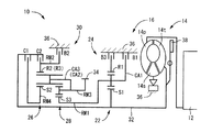
図1は、本発明が適用された車両用駆動装置10を説明する骨子図である。この車両用駆動装置10は、FF(フロントエンジン・フロントドライブ)型車両に好適に採用されるもので、走行用の駆動源としてエンジン12を備えている。内燃機関にて構成されるエンジン12の出力は、流体式伝動装置として機能するトルクコンバータ14、自動変速機16、図示しない作動歯車装置、一対の車軸などを介して左右の駆動輪に伝達されるようになっている。
FIG. 1 is a skeleton diagram illustrating a
上記トルクコンバータ14は、エンジン12のクランク軸に連結されたポンプ翼車14p、自動変速機16の入力軸32に連結されたタービン翼車14t、および一方向クラッチを介してハウジングケース36に連結されたステータ翼車14sを備えており、流体を介して動力伝達を行うようになっている。また、それらのポンプ翼車14pおよびタービン翼車14tの間には、ロックアップクラッチ38が設けられており、ロックアップクラッチ38が係合されるとポンプ翼車14pおよびタービン翼車14tが一体的に回転させられるようになっている。
The
自動変速機16は、シングルピニオン型の第1遊星歯車装置22を主体として構成されている第1変速部24と、シングルピニオン型の第2遊星歯車装置26およびダブルピニオン型の第3遊星歯車装置28を主体として構成されている第2変速部30とを同軸線上に有し、入力軸32の回転を変速して出力歯車34から出力する。入力軸32は、入力部材に相当するするもので、前記トルクコンバータ14のタービン翼車14tと一体的に回転させられているタービン軸であり、出力歯車34は出力部材に相当するもので、カウンタ軸を介して或いは直接的に差動歯車装置と噛み合い、左右の駆動輪を回転駆動させる。なお、この車両用自動変速機16および前記トルクコンバータ14は、中心線に対して略対称的に構成されており、図1では中心線の下半分が省略されている。
The
上記第1変速部24を構成している第1遊星歯車装置22は、サンギヤS1、キャリヤCA1、およびリングギヤR1の3つの回転要素を備えており、サンギヤS1が入力軸32に連結されて回転駆動させられると共に、リングギヤR1が第3ブレーキB3を介して選択的に非回転部材であるハウジングケース36に連結されることにより、キャリヤCA1が中間出力部材として入力軸32に対して減速回転させられて出力する。また、第2変速部30を構成している第2遊星歯車装置26および第3遊星歯車装置28は、一部が互いに連結されることによって4つの回転要素RM1乃至RM4が構成されており、具体的には、第3遊星歯車装置28のサンギヤS3によって第1回転要素RM1が構成され、第2遊星歯車装置26のリングギヤR2および第3遊星歯車装置28のリングギヤR3が互いに連結されて第2回転要素RM2が構成され、第2遊星歯車装置26のキャリヤCA2および第3遊星歯車装置28のキャリヤCA3が互いに連結されて第3回転要素RM3が構成され、第2遊星歯車装置26のサンギヤS2によって第4回転要素RM4が構成されている。上記第2遊星歯車装置26および第3遊星歯車装置28は、キャリヤCA2およびキャリヤCA3が共通の部材で構成されていると共に、リングギヤR2およびリングギヤR3が共通の部材にて構成されており、且つ第2遊星歯車装置26のピニオンギヤが第3遊星歯車装置28の第2ピニオンギヤを兼ねているラビニヨ式の遊星歯車列とされている。
The first
上記第1回転要素RM1(サンギヤS3)はブレーキB1によって選択的にハウジングケース36に連結されて回転停止させられ、第2回転要素RM2(リングギヤR2、R3)は第2ブレーキB2によって選択的にハウジングケース36に連結されて回転停止させられ、第4回転要素RM4(サンギヤS2)は第1クラッチC1を介して選択的に前記入力軸32に連結され、第2回転要素RM2(リングギヤR2、R3)は第2クラッチC2を介して選択的に入力軸32に連結され、第1回転要素RM1(サンギヤS3)は中間出力部材である第1遊星歯車装置22のキャリヤCA1に選択的に連結され、第3回転要素RM3(キャリヤCA2、CA3)は前記出力歯車34に一体的に連結されて回転を出力するようになっている。第1ブレーキB1乃至第3ブレーキB3、第1クラッチC1、第2クラッチC2は、何れも油圧シリンダによって摩擦係合させられる多板式の油圧式摩擦係合装置で、これらのブレーキおよびクラッチの係合解放状態が切り換えられることにより、前進6段および後進1段の各変速段が成立させられる。
The first rotation element RM1 (sun gear S3) is selectively connected to the
図2の作動表は、クラッチおよびブレーキの作動状態と各変速段との関係をまとめて示したもので、「○」は係合を表している。本実施例の車両用自動変速機16においては、2つのクラッチC1、C2および3つのブレーキB1乃至B3のうち何れか2つの係合によって前進6段の多段変速機が達成される。
The operation table of FIG. 2 collectively shows the relationship between the operation states of the clutch and the brake and the respective shift stages, and “◯” represents engagement. In the vehicle
図3は自動変速機16の前記第2変速部30を詳細に説明する要部断面図である。なお、第2変速部30は軸心Cに対して略対称であるため、その下側半分が省略されている。自動変速機16は、ハウジングケース36内にベアリングを介してハウジングケース36に相対回転可能に支持され軸心Cを中心に回転駆動する入力軸32、その入力軸32の径方向外側に複数個のブッシュを介して相対回転可能に支持されているシングルピニオン型の第2遊星歯車装置26およびダブルピニオン型の第3遊星歯車装置28、入力軸32と第2遊星歯車装置26との間に配置され第2遊星歯車装置26および第3遊星歯車装置28に入力軸32の回転を選択的に伝達する第1クラッチC1および第2クラッチC2、第2遊星歯車装置26および第3遊星歯車装置28の径方向外側に配置され第2遊星歯車装置26のリングギヤR2および第3遊星歯車装置28のリングギヤR3を選択的に回転停止させる第2ブレーキB2および一方向の回転を阻止する一方向クラッチF1を備えている。
FIG. 3 is a cross-sectional view of a main part for explaining the
入力軸32には、軸心Cに対して垂直に伸びる鍔部32aが形成されている。この鍔部32aの外周縁には、その外周縁に一体に溶接接合されると共に、ハウジングケース36に対して相対回転可能に支持されている円環状の基部材42が配置されている。この基部材42の第2遊星歯車装置26に接近する側の外周面には、第1クラッチC1の構成部材である第1摩擦係合要素44および第2クラッチC2の構成部材である第2摩擦係合要素46を支持するクラッチドラム48が一体に溶接接合されており、そのクラッチドラム48を覆うように第2クラッチピストン50が基部材42の外周面にシールを介して嵌め付けられている。
The
クラッチドラム48は、軸方向の一方に開口する有底円筒状部材であり、内周縁が基部材42の外周面に溶接接合されている略円板状の底部48aと、その底部48aの外周縁に連結される円筒状の筒部48bとで構成されている。
The
筒部48bの内周面には長手状にスプライン歯が設けられており、筒部48bの底部48a側には、第1クラッチC1を構成する第1摩擦係合要素44の一方の摩擦プレート52が複数枚スプライン嵌合されており、筒部48bの開口側には、第2クラッチC2を構成する第2摩擦係合要素46の一方の摩擦プレート52が複数枚スプライン嵌合されている。
Spline teeth are provided in a longitudinal shape on the inner peripheral surface of the
第1摩擦係合要素44は、前記筒部48bにスプライン嵌合されている一方の摩擦プレート52と、その摩擦プレート52の間に介在させられ、第2遊星歯車装置26のリングギヤR2に回転を伝達する第1クラッチハブ54の外周面にスプライン嵌合されている他方の複数枚の摩擦プレート56とで構成されている。
The first
一方、第2摩擦係合要素46は、前記筒部48bにスプライン嵌合されている一方の摩擦プレート52と、その摩擦プレート52の間に介在させられ、第2遊星歯車装置26および第3遊星歯車装置28のリングギヤR2、R3に回転を伝達する第2クラッチハブ58の外周面にスプライン嵌合されている他方の複数枚の摩擦プレート56とで構成されている。また、第2クラッチハブ58の外周面には一方向クラッチF1が接続されると共に、第2ブレーキB2の構成部材である第3摩擦係合要素60の一方の摩擦プレート56がスプライン嵌合されている。
On the other hand, the second
第3摩擦係合要素60は、第2クラッチハブ58の外周面にスプライン嵌合されている複数枚の一方の摩擦プレート56と、それら一方の摩擦プレート56の間に介在させられ、ハウジングケース36にスプライン嵌合されている他方の複数枚の摩擦プレート52とで構成されており、第3摩擦係合要素60の一方向クラッチF1とは反対側に位置しハウジングケース36に摺動可能に嵌め付けられているブレーキピストン61が第3摩擦係合要素60を押圧することによって第2ブレーキB2が係合させられる。
The third
前記クラッチドラム48と第1クラッチハブ54との間には第1摩擦係合要素44を押圧するための第1クラッチピストン62およびバネ受板64が配置されている。第1クラッチピストン62は、その内周面がシールを介して入力軸32に対して軸心方向に摺動可能に嵌め付けられ、外周面は第1摩擦係合要素44の方向に伸びる押圧部62aを備えている。バネ受板64は、入力軸32にスナップリング66によって軸心方向に移動不能に嵌め付けられている。また、第1クラッチピストン62とバネ受板64との間には、第1クラッチピストン62をクラッチドラム48側の方向に移動するように付勢するリターンスプリング68が介在されている。
Between the
前記第2クラッチピストン50のクラッチドラム48側とは反対側には、バネ受板70が基部材42の外周面にスナップリング72によって軸心方向に摺動不能に嵌め着けられており、第2クラッチピストン50とバネ受板70との間には第2クラッチピストン50をクラッチドラム48の底部48aに接近する方向に移動するように付勢するリターンスプリング74が介在されている。
On the opposite side of the second
第2クラッチピストン50は本発明のクラッチピストンに相当する。第2クラッチピストン50は、両端が開口する円筒状のシリンダ部材50aと、そのシリンダ部材50aの一端部内に嵌め入れられる円板状の底板部材50bと、スナップリング76とで構成されている。本実施例では、シリンダ部材50aおよび底板部材50bは、第1部材および第2部材に対応している。
The second
図4は、第2クラッチピストン50の構成を説明する簡略図である。シリンダ部材50aの内周面には、そのシリンダ部材50aの軸心方向に平行に伸びる長手状の複数本の位置決め突起78が等角度間隔に設けられており、底板部材50bが嵌め入れられる側の位置決め突起78の端面79は略矩形の平面形状を有している。この端面79に底板部材50bの一面側が当接するが、それぞれの位置決め突起78の端面79に当接し底板部材50bがシリンダ部材50aの軸心に対し垂直に固定されるように位置決め突起78の端面79はそれぞれ同じ軸心方向位置にされている。また、この位置決め突起78の端面79より円板状の底板部材50bの肉厚分だけ上方にはスナップリング76を嵌め着けるための内周溝80が設けられている。
FIG. 4 is a simplified diagram illustrating the configuration of the second
これより、このシリンダ部材50aの位置決め突起78の端面79に底板部材50bの一面側が当接され、底板部材50bの他面側は内周溝80にスナップリング76が嵌め着けられることによって底板部材50bは固定される。また、位置決め突起78は、シリンダ部材50aの他端部まで伸びているため、シリンダ部材50aの補強部材としても機能する。
As a result, one surface side of the
図3に戻り、第2クラッチピストン50は、基部材42の外周面にシールを介して嵌め付けられると共に、シリンダ部材50aに設けられてる複数本の位置決め突起78がクラッチドラム48の筒部48bに設けられている後述する図5の凹溝86内に嵌め入れられていることによって第2クラッチピストン50はクラッチドラム48と一体的に回転する。
Returning to FIG. 3, the second
図5は、第2クラッチピストン50とクラッチドラム48とを軸心Cに対して垂直な面で切断した要部断面図である。なお、図5を矢印Aの方向から見た断面図が図3に相当する。図5に示されるように、シリンダ部材50aの位置決め突起78は、クラッチドラム48の筒部48bの外周面に設けられている長手状の凹溝86内に軸心方向に摺動可能に嵌め入れられ、第2クラッチピストン50はクラッチドラム48に対して相対回転不能に支持されている。なお、第2クラッチピストン50に設けられている油孔90およびクラッチドラム48に設けられている油孔88は、第1摩擦係合要素44および第2摩擦係合要素46を潤滑した潤滑油が排出されるための油道となる。
FIG. 5 is a cross-sectional view of a main part in which the second
また、図3に示されるように、第2クラッチピストン50の第2摩擦係合要素46を押圧する側である他端部には、その他端部から軸心に向かって内周側に突き出すと共に、その内周縁からシリンダ部材50aの一端部に向かって突き出す円環状の押圧突部82が設けられている。
As shown in FIG. 3, the other end of the second
また、シリンダ部材50aのスナップリング76が嵌め着けられる内周溝80が設けられている一端部には、シリンダ部材50a外周側に向かって環状に肉厚が増加させられた増肉部84を有している。この増肉部84によって内周溝80の溝深さが増肉部84付近にまで達することが可能となっている。
Further, at one end portion where the inner
シリンダ部材50aは、アルミ合金で構成されており、鋳造によってすなわちアルミニウムダイキャストによって成形されている。これより、シリンダ部材50aに設けられている、押圧突部82、増肉部84および位置決め突起78などの比較的複雑な形状も金型によって一挙に得られるので、プレス加工、切削加工等の加工法に比べて比較的容易に成形することが可能となっている。
The
このように構成される油圧式摩擦係合装置において、ハウジングケース36の作動油供給油路92から作動油が供給されると、作動油は基部材42に設けられている作動油供給孔94を通り第2クラッチピストン50とクラッチドラム48の間に形成される油室96に作動油が供給される。この油室96はシール部材98によって油密とされており、供給された作動油の油圧によって、第2クラッチピストン50はリターンスプリング74側に前進する。この第2クラッチピストン50の前進によって第2クラッチピストン50の押圧突部82が第2摩擦係合要素46を押圧する。第2摩擦係合要素46の押圧突部82とは反対側では、第2摩擦係合要素46の摩擦プレート52、56の移動を阻止するスナップリング100が筒部48bの内周面に嵌め着けられているため第2摩擦係合要素46が係合させられる。
In the hydraulic friction engagement device configured as described above, when hydraulic oil is supplied from the hydraulic oil
この第2摩擦係合要素46の押圧の際には、第2クラッチピストン50の底板部材50bがスナップリング76を軸心Cに平行に押圧突部82と隔離する方向に押圧するため、スナップリング76によってシリンダ部材50aの両端部を互いに引っ張り合う方向に力が発生する。この引っ張り力に対してシリンダ部材50aの内周溝80の外周はシリンダ部材50aの肉厚が薄くなることから引っ張り応力も大きくなり耐久性の観点から問題となるが、本実施例では切欠が設けられておらず、円周方向全体でその力を受けることができ、更に、シリンダ部材50aの一端部に設けられている増肉部84によって補強されているため、本実施例では鉄に比べ強度的に劣るアルミニウム合金であっても耐久性を保持することが可能となる。
When the second
上述のように、本実施例によれば、両端が開口する円筒状のシリンダ部材50a、そのシリンダ部材50aの一端部内に嵌め入れられる円板状の底板部材50b、およびスナップリング76の複数の部材で構成される第2クラッチピストン50は、シリンダ部材50aの内周面には複数本の長手状の位置決め突起78を設け、その位置決め突起78の端面79に円板状の底板部材50bを当接させることによって、切欠を設けることなく底板部材50bをシリンダ部材50aの一端部内に嵌め入れることができるため、摩擦係合装置の係合の際にシリンダ部材50aに生じる引っ張り力をシリンダ部材50aの円周方向に連続する端部全体で受けることが可能となり、シリンダ部材50aの耐久性が向上する。
As described above, according to the present embodiment, the
また、本実施例によれば、シリンダ部材50aはアルミニウム合金で構成されていることによって、シリンダ部材50aの強度は鉄に比べ低くなるが、前述の第2クラッチピストン50の構成によって強度的にも問題なく使用が可能となり、さらに第2クラッチピストン50の軽量化が可能となる。
Further, according to the present embodiment, the
また、本実施例によれば、シリンダ部材50aに設けられている増肉部84、押圧突部84、および位置決め突起78等の比較的複雑な形状も鋳造によって成形されることで金型によって一挙に得られるため、プレス加工、切削加工等の他の加工法に比べ比較的容易に成形することができる。
In addition, according to the present embodiment, relatively complicated shapes such as the thickened
また、本実施例によれば、シリンダ部材50aの他端部には、内周側に向かって突き出し、且つその内周縁部からそのシリンダ部材50aの一端部に向かって突き出す押圧突部82が第2摩擦係合要素46を押圧するため、第2クラッチピストン50に推力を付与するための油室96と摩擦係合要素46との軸心方向距離が比較的離れていてもクラッチの係合が可能となる。
Further, according to the present embodiment, the other end of the
また、本実施例によれば、シリンダ部材50aの一端部には、外周側に向かって肉厚が増加させられた増肉部84を有し、前記一端部に設けられている内周溝80は増肉部84に到達する深さを有しているため、シリンダ部材50aの一端部の強度が増すためクラッチ係合の際に発生する引っ張り力に対する耐久力が向上すると共に、内周溝80の溝深さを比較的深くまで設けることができるため、スナップリング76の脱落を防止することができる。
Further, according to this embodiment, the
また、本実施例によれば、第2クラッチピストン50の位置決め突起78をクラッチドラム48の長手状の凹溝86に嵌め入れられることによって、第2クラッチピストン50およびクラッチドラム48が一体的に回転させられるため、径方向において小型な自動変速機となる。
Further, according to this embodiment, the second
以上、本発明の実施例を図面に基づいて詳細に説明したが、本発明はその他の態様においても適用される。 As mentioned above, although the Example of this invention was described in detail based on drawing, this invention is applied also in another aspect.
たとえば、本実施例では、位置決め突起78は第2クラッチピストン50の補強のため、シリンダ部材50aの他端部まで伸びているが、軽量化のために位置決め突起78の軸心方向の長さを短くして使用することもできる。
For example, in this embodiment, the
また、本実施例では、シリンダ部材50aはアルミニウム合金によって構成されているが、鉄等の他の金属材料で構成することもできる。
In the present embodiment, the
また、本実施例では、シリンダ部材50aは鋳造によって製作されているが、たとえばプレス加工や切削加工などの鋳造以外の方法で制作することもできる。
In the present embodiment, the
また、本実施例では、シリンダ部材50aの一端部側に増肉部84を設けているが、増肉部84を設けずに使用することもできる。
In the present embodiment, the thickened
また、本実施例では、シリンダ部材50aの位置決め突起78は等角度間隔に複数本配置されているが、特に等角度間隔にする必要はなく、更に、位置決め突起78を円周状に連続した形状にするなど位置決め突起78の形状は自由に変更することができる。
In the present embodiment, a plurality of
なお、上述したのはあくまでも一実施形態であり、本発明は当業者の知識に基づいて種々の変更、改良を加えた態様で実施することができる。 The above description is only an embodiment, and the present invention can be implemented in variously modified and improved forms based on the knowledge of those skilled in the art.
48:クラッチドラム 50:第2クラッチピストン 50a:シリンダ部材(第1部材) 50b:底板部材(第2部材) 76:スナップリング 78:位置決め突起 79:端面 80:内周溝 82:押圧突部 84:増肉部 凹溝:86
48: Clutch drum 50: Second
Claims (6)
前記第1部材の内周面には、該第1部材の軸心方向に平行に伸びる複数本の位置決め突起が設けられ、前記第2部材は、該複数の位置決め突起の端面に当接させられることによって前記第2部材の軸心方向の他方への移動が阻止されていることを特徴とする車両用自動変速機の摩擦係合装置。 A cylindrical first member having both ends open, a disc-shaped second member fitted into one end of the first member, and an inner circumferential groove formed on the inner peripheral surface of the one end of the first member A friction engagement device for an automatic transmission comprising a bottomed cylindrical clutch piston with a snap ring that is fitted to the second member and prevents one movement in the axial direction of the second member,
A plurality of positioning protrusions extending in parallel with the axial direction of the first member are provided on the inner peripheral surface of the first member, and the second member is brought into contact with end surfaces of the plurality of positioning protrusions. Accordingly, the movement of the second member in the axial direction in the other direction is prevented.
Priority Applications (3)
| Application Number | Priority Date | Filing Date | Title |
|---|---|---|---|
| JP2005228691A JP4337788B2 (en) | 2005-08-05 | 2005-08-05 | Friction engagement device for automatic transmission |
| US11/481,831 US7549523B2 (en) | 2005-08-05 | 2006-07-07 | Friction apply device of an automatic transmission |
| CNB2006101101363A CN100414132C (en) | 2005-08-05 | 2006-08-07 | Friction apply device of an automatic transmission |
Applications Claiming Priority (1)
| Application Number | Priority Date | Filing Date | Title |
|---|---|---|---|
| JP2005228691A JP4337788B2 (en) | 2005-08-05 | 2005-08-05 | Friction engagement device for automatic transmission |
Publications (2)
| Publication Number | Publication Date |
|---|---|
| JP2007046619A JP2007046619A (en) | 2007-02-22 |
| JP4337788B2 true JP4337788B2 (en) | 2009-09-30 |
Family
ID=37699642
Family Applications (1)
| Application Number | Title | Priority Date | Filing Date |
|---|---|---|---|
| JP2005228691A Expired - Fee Related JP4337788B2 (en) | 2005-08-05 | 2005-08-05 | Friction engagement device for automatic transmission |
Country Status (3)
| Country | Link |
|---|---|
| US (1) | US7549523B2 (en) |
| JP (1) | JP4337788B2 (en) |
| CN (1) | CN100414132C (en) |
Families Citing this family (6)
| Publication number | Priority date | Publication date | Assignee | Title |
|---|---|---|---|---|
| DE102008038100B4 (en) | 2008-03-29 | 2022-08-25 | Borgwarner Inc. | Multi-plate clutch with a hydraulically drivable actuating piston |
| DE102008016269B4 (en) | 2008-03-29 | 2019-08-08 | Borgwarner Inc. | Actuating piston for a friction clutch and friction clutch with such an actuating piston |
| WO2014201107A1 (en) * | 2013-06-11 | 2014-12-18 | Eaton Corporation | Anti-rotating hydraulic piston |
| EP3184462A1 (en) * | 2015-12-23 | 2017-06-28 | Sulzer Mixpac AG | Cartridge with reduced friction |
| JP2018071695A (en) * | 2016-10-31 | 2018-05-10 | 株式会社ダイナックス | Friction clutch |
| US10697489B1 (en) * | 2019-01-10 | 2020-06-30 | GM Global Technology Operations LLC | Snap ring having retention feature |
Family Cites Families (10)
| Publication number | Priority date | Publication date | Assignee | Title |
|---|---|---|---|---|
| US2879872A (en) * | 1956-04-12 | 1959-03-31 | Cornelius W Van Ranst | Speed range drive unit |
| US3047115A (en) * | 1960-06-29 | 1962-07-31 | Consolidation Coal Co | Fluid operated clutch |
| GB956219A (en) * | 1961-12-02 | 1964-04-22 | Daimler Benz Ag | Improvements in friction clutch arrangements comprising power means for the operation thereof |
| JPH07259886A (en) * | 1994-03-22 | 1995-10-09 | Yamakawa Ind Co Ltd | Shaft coupling structure |
| JP3926412B2 (en) * | 1996-07-17 | 2007-06-06 | 富士重工業株式会社 | Automatic transmission rotation speed detection device |
| JPH1132919A (en) | 1997-07-15 | 1999-02-09 | Hitachi Home Tec Ltd | Coffee filter |
| JP2004239404A (en) * | 2003-02-07 | 2004-08-26 | Nsk Warner Kk | Wet multiple-disc clutch |
| JP2005036911A (en) * | 2003-07-16 | 2005-02-10 | Nsk Warner Kk | Core plate for friction plate, friction plate, wet multiplate clutch and their manufacturing method |
| CN2649836Y (en) * | 2003-10-30 | 2004-10-20 | 浙江大学 | Multi-way valve with uniform-pressure-drop valve |
| JP4691932B2 (en) * | 2004-09-17 | 2011-06-01 | トヨタ自動車株式会社 | Automatic transmission clutch device |
-
2005
- 2005-08-05 JP JP2005228691A patent/JP4337788B2/en not_active Expired - Fee Related
-
2006
- 2006-07-07 US US11/481,831 patent/US7549523B2/en not_active Expired - Fee Related
- 2006-08-07 CN CNB2006101101363A patent/CN100414132C/en not_active Expired - Fee Related
Also Published As
| Publication number | Publication date |
|---|---|
| CN100414132C (en) | 2008-08-27 |
| JP2007046619A (en) | 2007-02-22 |
| US20070032335A1 (en) | 2007-02-08 |
| CN1908455A (en) | 2007-02-07 |
| US7549523B2 (en) | 2009-06-23 |
Similar Documents
| Publication | Publication Date | Title |
|---|---|---|
| JP4356679B2 (en) | Friction engagement device | |
| JP4259521B2 (en) | Automatic transmission for vehicles | |
| JP4720301B2 (en) | Automatic transmission clutch device | |
| US10180183B2 (en) | Automatic transmission | |
| US9068631B2 (en) | Automatic transmission | |
| JP4720302B2 (en) | Automatic transmission clutch device | |
| US10378615B2 (en) | Clutch and speed change device including the same | |
| US9784345B2 (en) | Transmission device | |
| JP4337788B2 (en) | Friction engagement device for automatic transmission | |
| US20090114501A1 (en) | Frictional engagement device | |
| JP3747913B2 (en) | Lubrication structure of friction engagement device | |
| WO2014156975A1 (en) | Power transmission device | |
| JP6119379B2 (en) | Power transmission device | |
| JP4798225B2 (en) | Automatic transmission | |
| JP2008309292A (en) | Snap ring of vehicular hydraulic frictional engaging device | |
| JP2008275032A (en) | Friction engagement device | |
| JP2007155071A (en) | Piston of automatic transmission for vehicle | |
| JPH0819996B2 (en) | Planetary gear type automatic transmission for vehicles | |
| JP4816310B2 (en) | Automatic transmission | |
| JP4613797B2 (en) | Fastening member for automatic transmission for vehicle | |
| JP2004156653A (en) | Lubricating structure of frictional engagement device | |
| JP2007092821A (en) | Friction engagement device | |
| JP6156201B2 (en) | Power transmission device | |
| JP2014190487A (en) | Transmission device | |
| JP2013190026A (en) | Transmission |
Legal Events
| Date | Code | Title | Description |
|---|---|---|---|
| A977 | Report on retrieval |
Free format text: JAPANESE INTERMEDIATE CODE: A971007 Effective date: 20090401 |
|
| TRDD | Decision of grant or rejection written | ||
| A01 | Written decision to grant a patent or to grant a registration (utility model) |
Free format text: JAPANESE INTERMEDIATE CODE: A01 Effective date: 20090609 |
|
| A01 | Written decision to grant a patent or to grant a registration (utility model) |
Free format text: JAPANESE INTERMEDIATE CODE: A01 |
|
| A61 | First payment of annual fees (during grant procedure) |
Free format text: JAPANESE INTERMEDIATE CODE: A61 Effective date: 20090622 |
|
| FPAY | Renewal fee payment (event date is renewal date of database) |
Free format text: PAYMENT UNTIL: 20120710 Year of fee payment: 3 |
|
| LAPS | Cancellation because of no payment of annual fees |