JP4337004B2 - Dust generation suppression device at the powder inlet - Google Patents
Dust generation suppression device at the powder inlet Download PDFInfo
- Publication number
- JP4337004B2 JP4337004B2 JP2008015691A JP2008015691A JP4337004B2 JP 4337004 B2 JP4337004 B2 JP 4337004B2 JP 2008015691 A JP2008015691 A JP 2008015691A JP 2008015691 A JP2008015691 A JP 2008015691A JP 4337004 B2 JP4337004 B2 JP 4337004B2
- Authority
- JP
- Japan
- Prior art keywords
- circumferential
- granular material
- holding tank
- opening
- wall
- Prior art date
- Legal status (The legal status is an assumption and is not a legal conclusion. Google has not performed a legal analysis and makes no representation as to the accuracy of the status listed.)
- Active
Links
Images


Description
本発明は、例えば、小麦粉等の穀物、セメント、砕石等の粉粒体投入口の発塵抑制装置に関する。 The present invention relates to an apparatus for suppressing dust generation, for example, at an inlet of a granular material such as cereal such as wheat flour, cement or crushed stone.
例えば、トラック等に荷積みした小麦粉等の農産物やセメント等の粉粒体をサイロやチェーンコンベア等の搬送装置やホッパ等の投入口を介して投入する際、粉塵が大量に発生する。よって、飛散した粉塵を作業者が吸込むことによる健康被害や粉塵爆発の危険性、又は周囲の床や施設等に粉塵が付着堆積して清掃が必要となる等の問題があった。 For example, a large amount of dust is generated when agricultural products such as wheat flour and powder particles such as cement loaded on a truck or the like are introduced through a conveying device such as a silo or a chain conveyor, or an inlet such as a hopper. Therefore, there have been problems such as health damage caused by the worker's inhalation of scattered dust, risk of explosion of dust, or dust adhering and accumulating on surrounding floors and facilities, etc.
また、特許文献1には、粉粒体の荷扱い時に粉塵が飛散するのを防止するのを目的とした集塵機能を有するホッパが提案されている。特許文献1のホッパでは、四周を囲むホッパの側壁の上端から側壁内方へ突出する邪魔板を四周に設けるとともに、ホッパの中央開口部に邪魔板の先端から垂下させて防風板を設けており、一方側の邪魔板に2枚の板を対向させて断面y形状に集塵口を設け、該対向させた2枚の板の少なくとも片方を開閉自在に構成している。粉粒体をホッパ内に投入した際には、中央開口部から垂下させた防風板によりホッパ内で発生する粉塵の一部をホッパ内に閉じ込めるとともに、集塵口を介してホッパの外部まで飛散した粉塵のうちホッパ上に落下した粉塵を集めてホッパ内に戻すものであった。 Further, Patent Document 1 proposes a hopper having a dust collecting function for the purpose of preventing dust from scattering when handling a granular material. The hopper of Patent Document 1, the baffle projecting from the upper end of the side wall of the hopper surrounding the four sides to the side walls inwardly is provided on the four sides, and provided with a windbreak plate by hanging from the tip of the baffle to the central opening of the hopper The two plates are opposed to the baffle plate on one side, and a dust collecting port is provided in a y-shaped cross section, and at least one of the two opposed plates is configured to be openable and closable. When the powder particles are put into the hopper, a part of the dust generated in the hopper is confined in the hopper by the windbreak plate suspended from the central opening and scattered outside the hopper through the dust collecting port. Dust that fell on the hopper was collected and returned to the hopper.
しかしながら、特許文献1のホッパでは、ホッパの上部側の邪魔板に集塵口を設けているが、例えば、ホッパの中央開口部から粉粒体を大量に投入した場合には、邪魔板の下端側を塞ぐように大量に保持されてしまう結果、該邪魔板による粉塵のホッパ内への閉じ込め機能が全く又はほとんど機能せず、ホッパ外部へ大量に粉塵が飛散してしまう問題があった。また、粉粒体の投入量がある程度少ない場合でも、中央開口部から垂下させた防風板の構成だけでは、粉塵のホッパ外への飛散を確実には防止できないため、上記のような健康被害、粉塵爆発等の問題を十分には解決できないものであった。 However, in the hopper of Patent Document 1, a dust collection port is provided in the baffle plate on the upper side of the hopper. For example, when a large amount of powder particles are charged from the central opening of the hopper, the lower end of the baffle plate As a result of being held in a large amount so as to close the side, the function of confining the dust inside the hopper by the baffle plate does not function at all or hardly, and there is a problem that a large amount of dust is scattered outside the hopper. In addition, even when the amount of the granular material input is small to some extent, the structure of the windbreak plate suspended from the central opening cannot reliably prevent dust from scattering outside the hopper. Problems such as dust explosions could not be solved sufficiently.
本発明は上記従来の課題に鑑みてなされたものであり、その一つの目的は、投入口から保持空間内に粉粒体を投入する際に、外部へ粉粒体からの粉塵が飛散するのを良好に防止でき、特に粉粒体を大量に投入した場合でも良好に粉塵の発生を抑制できる粉粒体投入口の発塵抑制装置を提供することにある。 The present invention has been made in view of the above-described conventional problems, and one object of the present invention is to disperse dust from the granular material to the outside when the granular material is charged into the holding space from the charging port. It is an object of the present invention to provide a dust generation suppressing device for a granular material inlet that can effectively prevent generation of dust, and particularly can suppress generation of dust even when a large amount of granular material is charged.
上記課題を解決するために本発明は、粉粒体の保持空間12を有する保持槽(24)の上部側に設けられた投入口14と、保持槽(24)の保持空間12に連通し、保持槽(24)内に投入された粉粒体からの粉塵を保持槽外に吸引排出する吸引装置16と、保持槽(24)の側壁22との間に空隙を開けて上部を閉鎖した状態で中央側にせり出した位置に設けられ、表面側を投入口14から投入される粉粒体の下降案内面とするとともに、裏面と保持槽(24)の側壁22との間に周状の連通空隙であって保持空間12に連通する周状空隙30を形成する周状垂壁18であり、投入される粉粒体が所定量より少ない場合には、投入口14から周状垂壁18の下方側を経由して吸引装置16による吸引経路に連通する第1の吸引経路R1を形成する周状垂壁18と、を含み、投入される粉粒体が所定量以上となると周状垂壁に設けられた開口32を介して吸引装置16による吸引経路と保持層(24)の外部とを連通させる第2の吸引経路R2を確保する吸引経路確保手段20を備え、吸引経路確保手段20は、投入される粉粒体自体の接触で周状垂壁18に形成された開口32の開閉シャッタ(34)を自動的に開放し吸引経路に連通させる接触開閉装置38からなることを特徴とする粉粒体投入口の発塵抑制装置10から構成される。発塵抑制装置10は、例えば、サイロや種々の貯留タンクの投入口、バケットコンベアやチェーンコンベア等の搬送装置や搬送車等の投入口、或いはそれらの投入口に取り付けられるホッパの投入口等、その他種々の粉粒体投入口に適用できる。周状垂壁18は、例えば、横断面が矩形状、その他の多角形状、円形状等任意の形状でよく、保持槽の横断面形状に対応して設けることとしてもよい。
In order to solve the above problems, the present invention communicates with the
また、接触開閉装置38は、一部を周状側壁18に枢着され他部を自由端として周状側壁の開口32を開閉する扉34を含むこととしてもよい。
Further, the contact opening /
また、扉38は、周状垂壁18に上端側を枢支され下端側を自由端として周状側壁の開口32を開閉することとしてもよい。
Moreover, the
また、扉34が設置される周状垂壁18の部分が垂直状壁28であることとしてもよい。
Further, the portion of the
また、保持槽(24)内であって、周状垂壁18を受けるように周状垂壁の直下部に篩部材42を水平状に設置したこととしてもよい。篩部材42は、例えば、グレーチング、金網、パンチ孔付板部材等、粉粒体の粒径に対応した任意の大きさの目を有するものでよい。篩部材42は、広面積の一枚のグレーチング材等で構成してもよいし、複数枚のグレーチング材を並設して構成してもよい。
Moreover, it is good also as having installed the
また、粉粒体の保持空間12を有する保持槽(24)の上部側に設けられた投入口14と、保持槽(24)の保持空間12に連通し、保持槽(24)内に投入された粉粒体からの粉塵を保持槽外に吸引排出する吸引装置16と、保持槽(24)の側壁22との間に空隙を開けて上部を閉鎖した状態で中央側にせり出した位置に設けられ、表面側を投入口14から投入される粉粒体の下降案内面とするとともに、裏面と保持槽(24)の側壁22との間に周状の連通空隙であって保持空間12に連通する周状空隙30を形成する周状垂壁18であり、投入される粉粒体が所定量より少ない場合には、投入口14から周状垂壁18の下方側を経由して吸引装置16による吸引経路に連通する第1の吸引経路R1を形成する周状垂壁18と、を含み、投入される粉粒体が所定量より少ない場合には周状垂壁18に設けられた開口32を開閉シャッタ(34)で閉鎖するとともに、投入される粉粒体が所定量以上となると該周状垂壁18に設けられた開口32の開閉シャッタ(34)を開放して吸引装置16による吸引経路と保持層(24)の外部とを連通させる第2の吸引経路を確保する吸引経路確保手段20を備えたことを特徴とする粉粒体投入口の発塵抑制装置10から構成される。吸引経路確保手段20は、投入される粉粒体が所定量より少ない場合には、周状垂壁18の開口32を閉鎖しておき、投入される粉粒体が所定量以上の場合に、周状垂壁18の開口32を開放する開閉装置を備えるとよい。この際、開閉装置は手動又は自動で開口32を開閉制御できる構成としてもよい。
In addition, the
本発明の粉粒体投入口の発塵抑制装置によれば、粉粒体の保持空間を有する保持槽の上部側に設けられた投入口と、保持槽の保持空間に連通し、保持槽内に投入された粉粒体からの粉塵を保持槽外に吸引排出する吸引装置と、保持槽の側壁との間に空隙を開けて上部を閉鎖した状態で中央側にせり出した位置に設けられ、表面側を投入口から投入される粉粒体の下降案内面とするとともに、裏面と保持槽の側壁との間に周状の連通空隙であって保持空間に連通する周状空隙を形成する周状垂壁であり、投入される粉粒体が所定量より少ない場合には、投入口から周状垂壁の下方側を経由して吸引装置による吸引経路に連通する第1の吸引経路を形成する周状垂壁と、を含み、投入される粉粒体が所定量以上となると周状垂壁に設けられた開口を介して吸引装置による吸引経路と保持層の外部とを連通させる第2の吸引経路を確保する吸引経路確保手段を備えたことから、保持槽内に投入される粉粒体が所定量より少ない場合には粉粒体から発生する粉塵が周状垂壁で粉塵の外部へ飛散するのを防止しつつ第1の吸引経路を介して吸引装置により吸引排出するとともに、投入される粉粒体が所定量以上となる場合でも吸引経路確保手段により第2の吸引経路を確保して粉粒体から発生する粉塵を吸引装置により確実に吸引排出することができる結果、粉粒体の投入量の多少に関わらず常に投入口から保持槽外部側への発塵を抑制でき、作業者の健康被害、粉塵爆発等を良好に防止できる。 According to the dust particle suppression device for the powder particle inlet of the present invention, the inlet is provided on the upper side of the holding tank having the powder holding space and the holding space of the holding tank. A suction device that sucks and discharges dust from the granular material charged to the outside of the holding tank, and a position where the gap is opened between the side walls of the holding tank and the upper part is closed, and is protruded to the center side. The surface side is used as a descending guide surface for the granular material charged from the charging port, and a circumferential communication space is formed between the back surface and the side wall of the holding tank so as to communicate with the holding space. If the amount of granular material to be charged is less than a predetermined amount, a first suction path that communicates with the suction path by the suction device via the lower side of the circumferential vertical wall is formed from the charging port An opening provided in the circumferential vertical wall when the amount of the granular material to be charged becomes a predetermined amount or more. A suction path securing means for securing a second suction path for communicating between the suction path of the suction device and the outside of the holding layer via the suction device, so that the number of powder particles put into the holding tank is less than a predetermined amount In this case, the dust generated from the granular material is sucked and discharged by the suction device through the first suction path while preventing the dust generated from the granular material from being scattered to the outside by the circumferential vertical wall. Even when the amount exceeds the fixed amount, the second suction path is secured by the suction path securing means, and the dust generated from the powder can be reliably sucked and discharged by the suction device. Regardless of this, it is always possible to suppress dust generation from the inlet to the outside of the holding tank, and it is possible to satisfactorily prevent worker health damage and dust explosion.
また、吸引経路確保手段は、投入される粉粒体自体の接触で周状垂壁に形成された開口の開閉シャッタを自動的に開放し吸引経路に連通させる接触開閉装置からなる構成とすることにより、投入された粉粒体が所定量以上となる場合に該粉粒体が周状垂壁に接触すると自動的にその開口を開放して第2の吸引経路を確実に確保でき、扉の開閉制御を簡便に行うことができ、実用性が高い。 Further, the suction path securing means includes a contact opening / closing device that automatically opens and closes the opening / closing shutter formed in the circumferential hanging wall by contact with the charged granular material itself and communicates with the suction path. Therefore, when the charged granular material exceeds a predetermined amount, when the granular material comes into contact with the circumferential hanging wall, the opening is automatically opened and the second suction path can be surely secured. Opening and closing control can be easily performed, and is highly practical.
また、接触開閉装置は、一部を周状側壁に枢着され他部を自由端として周状側壁の開口を開閉する扉を含む構成とすることにより、周状側壁に形成される開口の開閉シャッタ構造を簡単な構造で実現でき、メンテナンスも簡単に行える。 In addition, the contact opening / closing device includes a door that is pivotally attached to the peripheral side wall and opens and closes the opening of the peripheral side wall with the other part as a free end, thereby opening and closing the opening formed in the peripheral side wall. The shutter structure can be realized with a simple structure, and maintenance can be easily performed.
また、扉は、周状垂壁に上端側を枢支され下端側を自由端として周状側壁の開口を開閉する構成とすることにより、下端側を自由端としているので粉粒体が所定量以上となる場合には扉に接触した際に粉粒体に押されて容易かつ確実に開口を開放できるとともに、周状側壁の開口の開閉シャッタ構造を簡単かつシンプルな構造で製造できる。 In addition, the door has a structure in which the upper end side is pivotally supported by the circumferential vertical wall and the opening of the circumferential side wall is opened and closed with the lower end side as a free end. In the case described above, the opening can be easily and surely opened by being pressed by the granular material when it comes into contact with the door, and the opening / closing shutter structure for the opening of the peripheral side wall can be manufactured with a simple and simple structure.
また、扉が設置される周状垂壁の部分が垂直状壁であることから、投入した粉粒体が所定量以下の際には投入される粉粒体が直接扉に当たることがないとともに該扉が自重作用により閉鎖状態を良好に保持でき、簡単な構造で確実性が高い扉の開閉構成を具現できる。 In addition, since the part of the circumferential vertical wall where the door is installed is a vertical wall, when the charged granular material is less than a predetermined amount, the charged granular material does not directly hit the door and The door can maintain its closed state well due to its own weight, and the door can be opened and closed with simple structure and high reliability.
また、保持槽内であって、周状垂壁を受けるように周状垂壁の直下部に篩部材を水平状に設置した構成とすることにより、篩部材により例えば、粉粒体の粒径よりも大きな径の異物が保持槽内に投入されるのを防止できる。 In addition, in the holding tank, by adopting a configuration in which the sieving member is installed horizontally just below the circumferential stagnation wall so as to receive the circumferential sag wall, for example, the particle size of the granular material by the sieving member It is possible to prevent foreign matters having a larger diameter from being put into the holding tank.
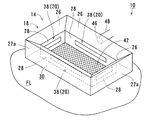
以下添付図面を参照しつつ本発明の粉粒体投入口の発塵抑制装置について説明する。本発明の粉粒体投入口の発塵抑制装置は、例えば、サイロやバケット搬送装置等に小麦、大麦その他の穀物、セメント、砕石、金属粉等の粉粒体を投入口から投入する際に、該粉粒体の微細な粒子が空気中に飛散して発塵するのを良好に抑制できるものである。図1ないし図4は、本発明の投入口の発塵抑制装置の一実施形態を示している。本実施形態において、粉粒体投入口の発塵抑制装置(以下、単に「発塵抑制装置」ともいう)10は、図1、図2、図3に示すように、粉粒体の保持空間12を有する保持槽の上部側に設けられた投入口14と、粉粒体からの粉塵を吸引排出する吸引装置16と、保持槽の中央側にせり出した位置に設けられた周状垂壁18と、吸引経路確保手段20と、を含む。
DESCRIPTION OF THE PREFERRED EMBODIMENTS Hereinafter, a dust generation suppressing device for a granular material inlet according to the present invention will be described with reference to the accompanying drawings. The dust generation suppressing device of the granular material inlet of the present invention is, for example, when a granular material such as wheat, barley or other grains, cement, crushed stone, metal powder, etc. is charged from the inlet into a silo or bucket conveying device. It is possible to satisfactorily suppress fine particles of the granular material from being scattered in the air and generating dust. FIGS. 1 to 4 show an embodiment of the dust control device for an inlet of the present invention. In the present embodiment, the dust generation suppression device (hereinafter also simply referred to as “dust generation suppression device”) 10 at the granular material inlet is a holding space for the granular material as shown in FIGS. 1, 2, and 3. 12, an
本実施形態では、図1、図3、図4に示すように、保持空間12を有する保持槽は、例えば、小麦粉等の粉粒体をサイロ等に搬送するチェーンコンベア100に粉粒体を投入するための漏斗型のホッパ24を含む。ホッパ24は、例えば、保持空間12の4周を囲む4つの金属製の側壁22を有し、上端側に平面視横長矩形状の投入口14を形成しつつ、下端側に投入口よりも小さく設けられた平面視矩形状の排出口23が形成されており、下方側に向けて徐々に狭くなる角錐形状となっている。排出口23には開閉自在な開閉板25が設けられており、開閉板の開放時に下方側に配置されたチェーンコンベア100内と連通して、保持空間内の粉粒体を該コンベア内に排出させる。本実施形態では、ホッパ24は、例えば、作業者や搬送用トラック等が自在に往来する作業用床面FLより床下位置に配置されている。ホッパ24の側壁22の上部22aは、テーパ状に傾斜した本体部分から床上に垂直状に立設しており、該上部22aに投入口14が設けられている。
In this embodiment, as shown in FIGS. 1, 3, and 4, the holding tank having the
図1に示すように、吸引装置16は、ホッパ24の保持空間12に連通し、ホッパ24内に投入された粉粒体からの粉塵をホッパ外に吸引排出する粉塵吸引手段である。吸引装置16は、例えば、ジャバラ管等の管部材48を介してホッパ24の側壁の上部側22aに接続された吸引ファン装置からなり、後述の周状空隙30に吸引口46を臨ませて保持空間12に連通した吸引経路を形成している。吸引装置16は、ホッパ24内に漂う粉粒体からの粉塵を空気とともに強制的に負圧吸引してホッパの外部側へ排出し、図示しない粉塵貯留部に吸引した粉塵を貯留する。なお、吸引した粉塵を集めてホッパ等の保持槽内やチェーンコンベア内に再び戻すようにしてもよい。図1上では、吸引装置16は作業用床面FLより下方位置に配置されているが、作業用床面FLより上方に設置してもよい。
As shown in FIG. 1, the
図1ないし図4に示すように、周状垂壁18は、ホッパ24の側壁との間に空隙を空けて上部を閉鎖した状態で中央側にせり出した位置に設けられている。周状垂壁18は、例えば、金属製壁部材から設けられており、ホッパの4つの側壁の上部22aの上端から中央側に向けて張り出してホッパの保持空間12の側壁側上部を閉鎖するせり出し壁部26と、各々のせり出し傾斜壁部26の先端側から中央に内孔を形成しつつ鉛直真下に垂下された4つの垂直状壁部28と、を含む。せり出し傾斜壁部26は、中央側に向けて傾斜しており、表面側を投入口から投入される粉粒体Mをスムーズに保持空間12へ案内する下降案内面を形成している。4つの垂直状壁部28は短い角筒形状に構成されており、縦に貫通する筒孔部を粉粒体の投入路として投入口と保持空間12とを連通させ、その表面側をせり出し傾斜壁部26の表面側と連続させて粉粒体Mの下降案内面としている。すなわち、周状垂壁18は、傾斜壁部26で構成される四角台錘筒と垂直状壁部28で構成される角筒とを接続した構造となっている。垂直状壁部28とせり出し傾斜壁部26の裏面側とホッパの側壁22との間に形成される空隙は、角環状に水平方向に周状に連通した周状空隙30からなる。周状空隙30は、下方側を開口しておりホッパの保持空間12と連通している。垂直状壁部28とせり出し壁部26とにより、ホッパ内に投入された粉粒体からの粉塵は周状空隙30に導入され、投入口14からホッパ外部へ飛散されるのを防止することができる。また周状空隙30内に導入された粉塵は、上述の側壁22に開口された吸引口46を介して、吸引装置16に吸引排出される。すなわち、周状垂壁18は、投入口14から垂直状壁部28の下方側を経由して吸引装置16による吸引経路に連通する第1の吸引経路R1を形成する。なお、周状垂壁18は、断面視で保持槽の側壁の上端から水平に壁をせり出させて略L字状に形成されていてもよいし、傾斜壁部26のみの構成すなわち曲折部を設けず直線状に中央側に向けて下り傾斜状に形成された構成としてもよいし、断面視で円弧状に中央側にせり出しつつ中央側を下方に垂れ下げた壁で形成されていてもよい。
As shown in FIG. 1 to FIG. 4, the
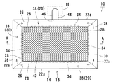
垂直状壁部28には、横方向に貫通した矩形状の開口32が設けられるとともに、開口32を開閉する開閉シャッタとしての扉34が設置されており、吸引経路確保手段20を構成している。吸引経路確保手段20は、投入される粉粒体が所定量以上となると垂直状壁部28の開口32を介して吸引装置16による吸引経路とホッパ24の外部とを連通させる第2の吸引経路R2を確保する。すなわち、吸引経路確保手段20は、図1の一点鎖線M2に示すように所定量以上に粉粒体が投入された保持空間内に堆積した粉粒体が垂直状壁部28の下端側を塞いで第1の吸引経路R1を閉鎖してしまう際に、吸引装置16による吸引経路とホッパ24の外部とを連通させた第2の吸引経路R2を確保して、吸引装置16による粉塵の吸引排出を実効させる。本実施形態では、吸引経路確保手段20は、粉粒体自体の接触で、開口32の扉34を自動的に開放する接触開閉装置38を含む。具体的には、扉34は垂直状壁部28に形成された開口32よりもやや大きな矩形状の板部材からなり、垂直状壁部28の裏面側に上端側を複数個の蝶番40を介して枢支され下端側を自由端としている。これにより、常時はすなわち粉粒体の投入量が少ない場合(図1上、破線M1)には、扉34の自重により閉鎖し、周状垂壁18によって形成される第1の吸引経路R1を確保する。投入口14から大量に投入された粉粒体がホッパ内に堆積して(図1、一点鎖線M2)粉粒体が扉34に接触する場合には、扉34は該粉粒体に押されて周状空隙内側に揺動し開口32を自動的に開放する。これにより、周状垂壁18の下端側を経由した第1の吸引経路R1が閉鎖される場合でも、第2の吸引経路R2を確保し、吸引装置による粉塵を吸引排出することができ、確実にホッパの外部での発塵を抑制できる。なお、粉粒体の投入量を感知するセンサ及び扉を強制的に開閉駆動させるモータやシリンダ等を含む駆動装置等を有する構成としてもよいが、本実施形態のような構成であれば簡単かつシンプルな構造で低コストで製造できる。また、接触開閉装置38は4つの垂直状壁部28の全てに設ける構成に限らず、1〜3つの垂直状壁部28だけに設けても良い。また、接触開閉装置38は1個の垂直状壁部28に複数個設けても良い。
The
図1、図2、図4に示すように、ホッパ24内には周状垂壁18を受けるように垂直状壁部28の直下部に篩部材42が設置されている。篩部材42は、例えば、平面視矩形状の複数のメッシュ孔が形成された金属製グレーチング板材からなり、ホッパ24の側壁22内側に溶接等により固定された受部44上に載置されて着脱自在に係止されている。本実施形態では、篩部材42は垂直状壁部28が形成する矩形状の開口より大きな面積で設けられており、4周縁をホッパの側壁22内面に当接(又は近接)させて垂直状壁部28の下端側を受ける。篩部材42は、ホッパ24内より離脱させることができ、例えば清掃を含むメンテナンスを簡便に行える。
As shown in FIGS. 1, 2, and 4, a sieving
なお、図5は投入口14周辺の構成の他の形態を示しており、図5では、ホッパ24の矩形状の投入口14の三辺縁部にコ字状に規制壁50が上方に立設されており、一方の長辺側のみ開放して形成されている。規制壁50を設けることにより、例えば、トラックT等を規制壁が設けられていない開放側から投入口14に横付けした状態で荷台から粉粒体を投入口14に投入する際に、発塵が外部に広がるのを効果的に防止できる。
FIG. 5 shows another form of the configuration around the
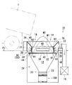
次に、図6を参照しつつ本実施形態に係る投入口の発塵抑制装置10の作用を説明する。粉粒体を投入口に投入する前に吸引装置16を作動させておき、図6に示すように、荷台に粉粒体を積載したトラックTを投入口14に近接させ、該荷台を傾けて粉粒体を投入口14から投入する。この際、粉粒体中の軽い粉塵はホッパの側壁22に当たって上部に舞い上がりながら飛散し保持空間内で発塵する。これらの飛散する粉塵は、周状垂壁18によって外部側への飛散を妨げられながら第1の吸引経路R1を介して周状空隙30に導入され吸引装置16によりホッパ外部へ吸引排出される。そして、図の一点鎖線M2に示すように、大量に粉粒体が投入されて垂直状壁部28に接触しつつ第1の吸引経路R1が閉鎖される場合には、該粉粒体が扉34を押し開いて垂直状壁部28に形成される開口32を自動的に開放し、吸引装置16による吸引経路とホッパの外部とを連通させる第2の吸引経路R2を確保する。この第2の吸引経路R2を形成することにより、第1の吸引経路R1が十分に形成されなくても吸引装置16による粉塵の吸引排出を行える。したがって、粉粒体の投入量の多少に関わらず常時高い発塵抑制効果を奏することができ、発塵による健康被害や粉塵爆発等を良好に防止できる。
Next, the operation of the dust
以上説明した本発明の粉粒体投入口の発塵抑制装置は、上記した実施形態のみの構成に限定されるものではなく、特許請求の範囲に記載した本発明の本質を逸脱しない範囲において、任意の改変を行ってもよい。 The dust generation suppressing device of the granular material inlet of the present invention described above is not limited to the configuration of the above-described embodiment alone, and in a range not departing from the essence of the present invention described in the claims, Any modification may be made.
本発明の粉粒体投入口の発塵抑制装置は、例えば、小麦粉その他の穀物、セメント、砕石、金属粉等が投入される貯留槽や搬送装置等の投入口又はそれらの投入口に取り付けられたホッパの投入口に適用される。 The dust particle suppression device of the granular material input port of the present invention is attached to an input port of a storage tank or a transfer device into which flour or other grains, cement, crushed stone, metal powder, etc. are input, or those input ports. Applicable to hopper inlets.
10 発塵抑制装置
12 保持空間
14 投入口
16 吸引装置
18 周状垂壁
20 吸引経路確保手段
22 側壁
24 ホッパ
28 垂直状壁部
30 周状空隙
32 開口
34 扉
38 接触開閉装置
42 篩部材
R1 第1の吸引経路
R2 第2の吸引経路
DESCRIPTION OF
Claims (6)
保持槽の保持空間に連通し、保持槽内に投入された粉粒体からの粉塵を保持槽外に吸引排出する吸引装置と、
保持槽の側壁との間に空隙を開けて上部を閉鎖した状態で中央側にせり出した位置に設けられ、表面側を投入口から投入される粉粒体の下降案内面とするとともに、裏面と保持槽の側壁との間に周状の連通空隙であって保持空間に連通する周状空隙を形成する周状垂壁であり、投入される粉粒体が所定量より少ない場合には、投入口から周状垂壁の下方側を経由して吸引装置による吸引経路に連通する第1の吸引経路を形成する周状垂壁と、を含み、
投入される粉粒体が所定量以上となると周状垂壁に設けられた開口を介して吸引装置による吸引経路と保持層の外部とを連通させる第2の吸引経路を確保する吸引経路確保手段を備え、
吸引経路確保手段は、投入される粉粒体自体の接触で周状垂壁に形成された開口の開閉シャッタを自動的に開放し吸引経路に連通させる接触開閉装置からなることを特徴とする粉粒体投入口の発塵抑制装置。 An inlet provided on the upper side of a holding tank having a holding space for powder particles,
A suction device that communicates with the holding space of the holding tank and sucks and discharges dust from the granular material charged into the holding tank to the outside of the holding tank;
Provided at a position protruding to the center side with a gap opened between the holding tank side wall and the upper part closed, and the surface side as a descending guide surface of the granular material charged from the charging port, and the back surface It is a circumferential vertical wall that forms a circumferential communication gap between the holding tank and the side wall of the holding tank and communicates with the holding space. A circumferential vertical wall that forms a first suction path that communicates with the suction path by the suction device via the lower side of the circumferential vertical wall from the mouth, and
A suction path securing means for securing a second suction path for communicating the suction path by the suction device and the outside of the holding layer through an opening provided in the circumferential hanging wall when the amount of the granular material to be charged exceeds a predetermined amount. equipped with a,
The suction path securing means comprises a contact opening / closing device that automatically opens and closes the opening / closing shutter formed in the circumferential hanging wall by the contact of the charged granular material itself and communicates with the suction path. Dust generation suppression device at the grain inlet.
保持槽の保持空間に連通し、保持槽内に投入された粉粒体からの粉塵を保持槽外に吸引排出する吸引装置と、A suction device that communicates with the holding space of the holding tank and sucks and discharges dust from the granular material charged into the holding tank to the outside of the holding tank;
保持槽の側壁との間に空隙を開けて上部を閉鎖した状態で中央側にせり出した位置に設けられ、表面側を投入口から投入される粉粒体の下降案内面とするとともに、裏面と保持槽の側壁との間に周状の連通空隙であって保持空間に連通する周状空隙を形成する周状垂壁であり、投入される粉粒体が所定量より少ない場合には、投入口から周状垂壁の下方側を経由して吸引装置による吸引経路に連通する第1の吸引経路を形成する周状垂壁と、を含み、Provided at a position protruding to the center side with a gap opened between the holding tank side wall and the upper part closed, and the surface side as a descending guide surface of the granular material charged from the inlet, It is a circumferential vertical wall that forms a circumferential communication gap between the holding tank and the side wall of the holding tank and communicates with the holding space. A circumferential vertical wall that forms a first suction path that communicates with the suction path by the suction device via the lower side of the circumferential vertical wall from the mouth, and
投入される粉粒体が所定量より少ない場合には周状垂壁に設けられた開口を開閉シャッタで閉鎖するとともに、投入される粉粒体が所定量以上となると該周状垂壁に設けられた開口の開閉シャッタを開放して吸引装置による吸引経路と保持層の外部とを連通させる第2の吸引経路を確保する吸引経路確保手段を備えたことを特徴とする粉粒体投入口の発塵抑制装置。When the amount of granular material to be charged is less than a predetermined amount, the opening provided in the circumferential wall is closed with an opening / closing shutter, and when the amount of granular material to be charged exceeds a predetermined amount, the opening is provided on the circumferential wall. And a suction path securing means for securing a second suction path that opens the opening / closing shutter of the opening to establish communication between the suction path of the suction device and the outside of the holding layer. Dust suppression device.
Priority Applications (1)
| Application Number | Priority Date | Filing Date | Title |
|---|---|---|---|
| JP2008015691A JP4337004B2 (en) | 2008-01-26 | 2008-01-26 | Dust generation suppression device at the powder inlet |
Applications Claiming Priority (1)
| Application Number | Priority Date | Filing Date | Title |
|---|---|---|---|
| JP2008015691A JP4337004B2 (en) | 2008-01-26 | 2008-01-26 | Dust generation suppression device at the powder inlet |
Publications (2)
| Publication Number | Publication Date |
|---|---|
| JP2009173421A JP2009173421A (en) | 2009-08-06 |
| JP4337004B2 true JP4337004B2 (en) | 2009-09-30 |
Family
ID=41028971
Family Applications (1)
| Application Number | Title | Priority Date | Filing Date |
|---|---|---|---|
| JP2008015691A Active JP4337004B2 (en) | 2008-01-26 | 2008-01-26 | Dust generation suppression device at the powder inlet |
Country Status (1)
| Country | Link |
|---|---|
| JP (1) | JP4337004B2 (en) |
Cited By (2)
| Publication number | Priority date | Publication date | Assignee | Title |
|---|---|---|---|---|
| CN103466223A (en) * | 2013-09-25 | 2013-12-25 | 牧原食品股份有限公司 | Large-scale aquaculture feed tank and manufacturing method thereof |
| CN107055134A (en) * | 2017-01-24 | 2017-08-18 | 上海应用技术大学 | Discharging opening dust control device |
Families Citing this family (8)
| Publication number | Priority date | Publication date | Assignee | Title |
|---|---|---|---|---|
| CN102556693B (en) * | 2010-12-13 | 2014-03-26 | 软控股份有限公司 | Dust exhaust hood for weighing material and method thereof |
| CN104941376A (en) * | 2015-07-01 | 2015-09-30 | 华侨大学 | Dust collection device and method |
| JP7053175B2 (en) * | 2017-06-21 | 2022-04-12 | アマノ株式会社 | Dust collection system |
| CN108147161A (en) * | 2017-09-19 | 2018-06-12 | 青岛科技大学 | A kind of dedusting closure assembly of anti-dust loss |
| CN109261975A (en) * | 2018-10-19 | 2019-01-25 | 赣州海创钨业有限公司 | Blanking device is used in a kind of production of tungsten powder |
| JP6916826B2 (en) * | 2019-02-25 | 2021-08-11 | パンパシフィック・カッパー株式会社 | Dust generation control mechanism and copper concentrate storage device |
| KR102135542B1 (en) * | 2020-02-25 | 2020-07-17 | 백성훈 | Dust Scatter Prevention Device |
| KR102286982B1 (en) * | 2020-11-20 | 2021-08-05 | 최점숙 | Mortar composition manufacturing equipment and concrete repair method thereof |
-
2008
- 2008-01-26 JP JP2008015691A patent/JP4337004B2/en active Active
Cited By (4)
| Publication number | Priority date | Publication date | Assignee | Title |
|---|---|---|---|---|
| CN103466223A (en) * | 2013-09-25 | 2013-12-25 | 牧原食品股份有限公司 | Large-scale aquaculture feed tank and manufacturing method thereof |
| CN103466223B (en) * | 2013-09-25 | 2016-03-02 | 牧原食品股份有限公司 | The method for making of a kind of large-scale breeding feed tank and batch can |
| CN107055134A (en) * | 2017-01-24 | 2017-08-18 | 上海应用技术大学 | Discharging opening dust control device |
| CN107055134B (en) * | 2017-01-24 | 2020-04-28 | 上海应用技术大学 | Discharge port dust control device |
Also Published As
| Publication number | Publication date |
|---|---|
| JP2009173421A (en) | 2009-08-06 |
Similar Documents
| Publication | Publication Date | Title |
|---|---|---|
| JP4337004B2 (en) | Dust generation suppression device at the powder inlet | |
| CA1279836C (en) | Bulk material chute system | |
| NO335950B1 (en) | Bulk Loading Device | |
| WO2001064558A1 (en) | Device for capturing dust in the loading of concrete mixer trucks | |
| JPS63165206A (en) | Dust controller for hopper | |
| CN213355818U (en) | A dust collector and bucket elevator for bucket elevator | |
| CN109761072B (en) | Receiving bin device | |
| KR200393574Y1 (en) | Mobile bulk hopper | |
| CN215088622U (en) | Wheat edulcoration device | |
| KR101752903B1 (en) | dust collecting apparatus for tank lorry | |
| CN211801181U (en) | Be used for broken loading attachment of cubic material | |
| CN219008702U (en) | Dust-free hopper for bulk cargo loading and unloading | |
| JP3170495U (en) | Fertilizer delivery container equipment | |
| CN205771105U (en) | Feeding system | |
| CN211254427U (en) | Material conveying device | |
| JP7430496B2 (en) | Loading device for silo | |
| KR102561122B1 (en) | Shatter-proof and powder quantity supply device to prevent air pollution | |
| JP7430497B2 (en) | Loading device for silo | |
| JP2000247447A (en) | Dust collector for load receiving device | |
| CN218319596U (en) | Feeding device for large sample equipment | |
| CN218662436U (en) | Ton bag receiving device for bulk feed packaging | |
| CN220077956U (en) | Dock receiving hopper with multistage dust suppression device | |
| CN217897411U (en) | Dust-absorbing material shed and receiving groove | |
| JP7335806B2 (en) | Silo loading device | |
| CN205708462U (en) | A kind of elevator of improved vertical improving material |
Legal Events
| Date | Code | Title | Description |
|---|---|---|---|
| TRDD | Decision of grant or rejection written | ||
| A01 | Written decision to grant a patent or to grant a registration (utility model) |
Free format text: JAPANESE INTERMEDIATE CODE: A01 Effective date: 20090602 |
|
| A01 | Written decision to grant a patent or to grant a registration (utility model) |
Free format text: JAPANESE INTERMEDIATE CODE: A01 |
|
| A61 | First payment of annual fees (during grant procedure) |
Free format text: JAPANESE INTERMEDIATE CODE: A61 Effective date: 20090616 |
|
| R150 | Certificate of patent or registration of utility model |
Free format text: JAPANESE INTERMEDIATE CODE: R150 Ref document number: 4337004 Country of ref document: JP Free format text: JAPANESE INTERMEDIATE CODE: R150 |
|
| FPAY | Renewal fee payment (event date is renewal date of database) |
Free format text: PAYMENT UNTIL: 20120710 Year of fee payment: 3 |
|
| FPAY | Renewal fee payment (event date is renewal date of database) |
Free format text: PAYMENT UNTIL: 20120710 Year of fee payment: 3 |
|
| FPAY | Renewal fee payment (event date is renewal date of database) |
Free format text: PAYMENT UNTIL: 20130710 Year of fee payment: 4 |
|
| R250 | Receipt of annual fees |
Free format text: JAPANESE INTERMEDIATE CODE: R250 |
|
| R250 | Receipt of annual fees |
Free format text: JAPANESE INTERMEDIATE CODE: R250 |
|
| S111 | Request for change of ownership or part of ownership |
Free format text: JAPANESE INTERMEDIATE CODE: R313111 |
|
| R350 | Written notification of registration of transfer |
Free format text: JAPANESE INTERMEDIATE CODE: R350 |
|
| R250 | Receipt of annual fees |
Free format text: JAPANESE INTERMEDIATE CODE: R250 |
|
| R250 | Receipt of annual fees |
Free format text: JAPANESE INTERMEDIATE CODE: R250 |
|
| S111 | Request for change of ownership or part of ownership |
Free format text: JAPANESE INTERMEDIATE CODE: R313113 |
|
| R350 | Written notification of registration of transfer |
Free format text: JAPANESE INTERMEDIATE CODE: R350 |
|
| R250 | Receipt of annual fees |
Free format text: JAPANESE INTERMEDIATE CODE: R250 |
|
| R250 | Receipt of annual fees |
Free format text: JAPANESE INTERMEDIATE CODE: R250 |
|
| R250 | Receipt of annual fees |
Free format text: JAPANESE INTERMEDIATE CODE: R250 |
|
| R250 | Receipt of annual fees |
Free format text: JAPANESE INTERMEDIATE CODE: R250 |
|
| R250 | Receipt of annual fees |
Free format text: JAPANESE INTERMEDIATE CODE: R250 |
|
| R250 | Receipt of annual fees |
Free format text: JAPANESE INTERMEDIATE CODE: R250 |
|
| R250 | Receipt of annual fees |
Free format text: JAPANESE INTERMEDIATE CODE: R250 |
|
| R250 | Receipt of annual fees |
Free format text: JAPANESE INTERMEDIATE CODE: R250 |