JP4336750B2 - Apparatus, system and kit for collecting effluent from individuals - Google Patents
Apparatus, system and kit for collecting effluent from individuals Download PDFInfo
- Publication number
- JP4336750B2 JP4336750B2 JP2003546808A JP2003546808A JP4336750B2 JP 4336750 B2 JP4336750 B2 JP 4336750B2 JP 2003546808 A JP2003546808 A JP 2003546808A JP 2003546808 A JP2003546808 A JP 2003546808A JP 4336750 B2 JP4336750 B2 JP 4336750B2
- Authority
- JP
- Japan
- Prior art keywords
- reservoir
- insertable member
- conduit
- instrument
- body cavity
- Prior art date
- Legal status (The legal status is an assumption and is not a legal conclusion. Google has not performed a legal analysis and makes no representation as to the accuracy of the status listed.)
- Expired - Lifetime
Links
Images


Classifications
-
- A—HUMAN NECESSITIES
- A61—MEDICAL OR VETERINARY SCIENCE; HYGIENE
- A61M—DEVICES FOR INTRODUCING MEDIA INTO, OR ONTO, THE BODY; DEVICES FOR TRANSDUCING BODY MEDIA OR FOR TAKING MEDIA FROM THE BODY; DEVICES FOR PRODUCING OR ENDING SLEEP OR STUPOR
- A61M1/00—Suction or pumping devices for medical purposes; Devices for carrying-off, for treatment of, or for carrying-over, body-liquids; Drainage systems
- A61M1/71—Suction drainage systems
- A61M1/77—Suction-irrigation systems
-
- A—HUMAN NECESSITIES
- A61—MEDICAL OR VETERINARY SCIENCE; HYGIENE
- A61F—FILTERS IMPLANTABLE INTO BLOOD VESSELS; PROSTHESES; DEVICES PROVIDING PATENCY TO, OR PREVENTING COLLAPSING OF, TUBULAR STRUCTURES OF THE BODY, e.g. STENTS; ORTHOPAEDIC, NURSING OR CONTRACEPTIVE DEVICES; FOMENTATION; TREATMENT OR PROTECTION OF EYES OR EARS; BANDAGES, DRESSINGS OR ABSORBENT PADS; FIRST-AID KITS
- A61F5/00—Orthopaedic methods or devices for non-surgical treatment of bones or joints; Nursing devices; Anti-rape devices
- A61F5/44—Devices worn by the patient for reception of urine, faeces, catamenial or other discharge; Portable urination aids; Colostomy devices
- A61F5/451—Genital or anal receptacles
-
- A—HUMAN NECESSITIES
- A61—MEDICAL OR VETERINARY SCIENCE; HYGIENE
- A61M—DEVICES FOR INTRODUCING MEDIA INTO, OR ONTO, THE BODY; DEVICES FOR TRANSDUCING BODY MEDIA OR FOR TAKING MEDIA FROM THE BODY; DEVICES FOR PRODUCING OR ENDING SLEEP OR STUPOR
- A61M1/00—Suction or pumping devices for medical purposes; Devices for carrying-off, for treatment of, or for carrying-over, body-liquids; Drainage systems
- A61M1/71—Suction drainage systems
- A61M1/78—Means for preventing overflow or contamination of the pumping systems
- A61M1/784—Means for preventing overflow or contamination of the pumping systems by filtering, sterilising or disinfecting the exhaust air, e.g. swellable filter valves
-
- A—HUMAN NECESSITIES
- A61—MEDICAL OR VETERINARY SCIENCE; HYGIENE
- A61M—DEVICES FOR INTRODUCING MEDIA INTO, OR ONTO, THE BODY; DEVICES FOR TRANSDUCING BODY MEDIA OR FOR TAKING MEDIA FROM THE BODY; DEVICES FOR PRODUCING OR ENDING SLEEP OR STUPOR
- A61M1/00—Suction or pumping devices for medical purposes; Devices for carrying-off, for treatment of, or for carrying-over, body-liquids; Drainage systems
- A61M1/84—Drainage tubes; Aspiration tips
- A61M1/85—Drainage tubes; Aspiration tips with gas or fluid supply means, e.g. for supplying rinsing fluids or anticoagulants
-
- A—HUMAN NECESSITIES
- A61—MEDICAL OR VETERINARY SCIENCE; HYGIENE
- A61M—DEVICES FOR INTRODUCING MEDIA INTO, OR ONTO, THE BODY; DEVICES FOR TRANSDUCING BODY MEDIA OR FOR TAKING MEDIA FROM THE BODY; DEVICES FOR PRODUCING OR ENDING SLEEP OR STUPOR
- A61M13/00—Insufflators for therapeutic or disinfectant purposes, i.e. devices for blowing a gas, powder or vapour into the body
- A61M13/003—Blowing gases other than for carrying powders, e.g. for inflating, dilating or rinsing
-
- A—HUMAN NECESSITIES
- A61—MEDICAL OR VETERINARY SCIENCE; HYGIENE
- A61M—DEVICES FOR INTRODUCING MEDIA INTO, OR ONTO, THE BODY; DEVICES FOR TRANSDUCING BODY MEDIA OR FOR TAKING MEDIA FROM THE BODY; DEVICES FOR PRODUCING OR ENDING SLEEP OR STUPOR
- A61M2209/00—Ancillary equipment
- A61M2209/08—Supports for equipment
- A61M2209/084—Supporting bases, stands for equipment
-
- A—HUMAN NECESSITIES
- A61—MEDICAL OR VETERINARY SCIENCE; HYGIENE
- A61M—DEVICES FOR INTRODUCING MEDIA INTO, OR ONTO, THE BODY; DEVICES FOR TRANSDUCING BODY MEDIA OR FOR TAKING MEDIA FROM THE BODY; DEVICES FOR PRODUCING OR ENDING SLEEP OR STUPOR
- A61M2210/00—Anatomical parts of the body
- A61M2210/10—Trunk
- A61M2210/1042—Alimentary tract
- A61M2210/1067—Anus
Abstract
Description
本出願は、2001年11月21日に出願された米国仮出願第60/330,072号の優先権を主張し、その全体を参考のために本明細書に引用する。本発明は、医療または診断処置の間または後に個人からの排出物を集めるための器具、システムおよびキットに関する。本明細書において、「排出物」という用語は、個人の身体の内部からの固体、半固体、液体、または気体のいずれかを含み、かつこれらに限定されない。代替の実施形態では、本発明は、媒体および排出物の双方向の流れを提供する。これにより、医療または診断処置を受ける個人の体腔に、および体腔から、所望の媒体が通過することができ、同時に、排出物を体腔からリザーバに流れさせ、排出物が媒体の流れを妨げたり、医療または診断処置の実施に用いられる機器に接触したりすることを防止する。本発明は、媒体および排出物が、意図される目的位置に達することができるような、媒体および排出物の双方向の流れを可能にする。本明細書では、「媒体」という用語は、有益な医療または診断処置を実施するために個人に対し投与される、固体、半固体、液体または気体のいずれかを含み、かつこれらに限定されない。 This application claims priority from US Provisional Application No. 60 / 330,072, filed Nov. 21, 2001, which is hereby incorporated by reference in its entirety. The present invention relates to instruments, systems and kits for collecting effluent from individuals during or after medical or diagnostic procedures. As used herein, the term “exhaust” includes, but is not limited to, any solid, semi-solid, liquid, or gas from within the individual's body. In an alternative embodiment, the present invention provides a bidirectional flow of media and effluent. This allows the desired medium to pass into and out of the body cavity of and from the individual undergoing the medical or diagnostic procedure, while at the same time causing the effluent to flow from the body cavity to the reservoir, the effluent obstructing the flow of the medium, Prevent contact with equipment used to perform medical or diagnostic procedures. The present invention allows bi-directional flow of media and effluent such that the media and effluent can reach the intended destination location. As used herein, the term “vehicle” includes, but is not limited to, any of a solid, semi-solid, liquid, or gas that is administered to an individual to perform a beneficial medical or diagnostic procedure.
医療または診断処置の間に個人からの排出物を集めるための現在の処置は、特に、様々な衛生上の問題を提起する。多くの場合、個人は、処置の間に排出物を集めるための適切な容器に繋がれておらず、処置を行う間またはその後に、体液およびガスの漏れ、汚染、雑音および悪臭を起こし、これらを漏出してしまう。また、診断を目的として、個人の排出物を観察し、処置の間に排出された排出物のすべてまたは一部を集めることも必要であろう。これは、現在知られている以下の技術の場合、しばしば不都合または困難である。 Current procedures for collecting effluent from individuals during medical or diagnostic procedures, in particular, pose various hygiene problems. In many cases, individuals are not connected to a suitable container to collect effluent during the procedure, causing fluid and gas leaks, contamination, noise, and odors during or after the procedure. Will leak. For diagnostic purposes, it may also be necessary to observe individual emissions and collect all or part of the emissions emitted during the procedure. This is often inconvenient or difficult for the following techniques currently known:
例えば、CT撮影その他を含みかつこれに限定されない胃腸撮影による診断の実施は、処置の前および間に、所望の身体部位を膨張させることで促進される。理想的には、処置の間に膨張を維持して、最も正確な画像を得る。現在、個人の直腸に挿入された直腸カテーテルの近端に吹込み器を直接接続して、検査の前および間に個人の結腸または他の身体部位を膨張させることが知られている。この装置により、例えば空気またはCO2が結腸に導入される。しかしながら、コスト的な制限により、吹込み機器は複数の個人に対し使用される。この点で、他の患者への使用により機器が汚染されないようにすることが重要である。吹込み処置の間に、大便などの排出物が頻繁に患者から排出され、しばしば吹込み機器に接触し、これを汚染する。 For example, performing a diagnosis by gastrointestinal imaging, including but not limited to CT imaging, etc. is facilitated by inflating the desired body part before and during the procedure. Ideally, expansion is maintained during the procedure to obtain the most accurate image. Currently, it is known to connect a blower directly to the proximal end of a rectal catheter inserted into a person's rectum to inflate the person's colon or other body part before and during the examination. With this device, for example, air or CO 2 is introduced into the colon. However, due to cost limitations, blowing devices are used for multiple individuals. In this regard, it is important to ensure that the device is not contaminated by use with other patients. During the insufflation procedure, stool or other effluent is frequently expelled from the patient and often contacts and contaminates the insufflation device.
上述した先行技術の不利な点は、本発明によって部分的に軽減される。例えば、代替の一実施形態においては、本発明は、医療または診断処置の間あるいは後に、個人の体腔内への媒体の投与に用いられる導管に接続された、排出物集積リザーバを提供する。これにより、処置の開始と共に排出される排出物はいずれも、このリザーバ内に移動して集められ、排出物が媒体の投与を妨げることを防ぐ。排出された排出物がリザーバ内にある状態で、所望の媒体が、導管を通って、個人の腔内に自由に移動できる。代替の一実施形態においては、本発明は、効率的な使い捨て器具を提供するので、吹込み装置との使用に適している。この使い捨て器具により、吹込み器の清潔および/または無菌状態を維持しながら、媒体を患者に通すことができ、これにより吹込み器を複数の個人に対し使用することができる。他の実施形態においては、膨張ガスが双方向に自由に流れることができ、これにより電空式吹込み器の圧力感知特性を活用することを可能にする。これは、例えば一定のユーザ設定圧力による腔(例えば結腸)の自動的な膨張に用いられる。 The disadvantages of the prior art described above are partially alleviated by the present invention. For example, in an alternative embodiment, the present invention provides an effluent accumulation reservoir connected to a conduit used for administration of media into a body cavity of an individual during or after a medical or diagnostic procedure. This ensures that any effluent that is expelled at the start of the treatment will move into the reservoir and be collected, preventing the effluent from interfering with the administration of the medium. With the discharged waste in the reservoir, the desired medium can freely move through the conduit and into the individual's cavity. In an alternative embodiment, the present invention provides an efficient disposable device and is suitable for use with a blowing device. This disposable device allows the media to pass through the patient while maintaining the cleanness and / or sterility of the insufflator, which allows the insufflator to be used for multiple individuals. In other embodiments, the inflation gas can flow freely in both directions, thereby allowing the pressure sensing characteristics of the electropneumatic blower to be exploited. This is used, for example, for automatic inflation of a cavity (eg, colon) with a constant user set pressure.
また、本発明の他の実施形態においては、本発明と医療または診断処置の実施に用いられる機器との間の接続位置の前に、バリアが配置される。これにより、処置の間にリザーバから漏れ出る排出物が機器に接触できないようになっている。排出物リザーバへの各開口部の前に配置されたバリアにより、排出された大便/排出物を容易に収容することができ、散乱を最小化し、処置の終わりに、排出物の処分を容易にする。 In another embodiment of the present invention, a barrier is disposed in front of a connection position between the present invention and a device used for performing a medical or diagnostic procedure. This prevents effluent leaking from the reservoir during the procedure from contacting the device. A barrier placed in front of each opening to the effluent reservoir can easily accommodate the discharged stool / effluent, minimizing scatter and facilitating disposal of the effluent at the end of the procedure To do.
したがって、本発明の目的は、個人からの排出物を集める器具、システム、およびキットを提供することである。 Accordingly, it is an object of the present invention to provide instruments, systems, and kits that collect effluent from individuals.
本発明のさらなる目的は、胃腸撮影または内視鏡検査を含みかつこれらに限定されない医療または診断処置の間あるいは後の、個人からの排出物の集積における改善を提供することである。 It is a further object of the present invention to provide an improvement in the collection of effluents from individuals during or after medical or diagnostic procedures, including but not limited to gastrointestinal imaging or endoscopy.
本発明のさらなる目的は、媒体および排出物の双方向の流れを提供することである。これにより、医療または診断処置を受ける個人の内腔に、および内腔から、媒体が通過することができ、同時に、排出物を内腔からリザーバに流れさせ、個人からの排出物が医療または診断処置に関連して用いられる機器に接触することを防止する。 A further object of the present invention is to provide a bidirectional flow of media and effluent. This allows the medium to pass into and out of the lumen of the individual undergoing medical or diagnostic procedures, while at the same time causing the effluent to flow from the lumen to the reservoir, the effluent from the individual being medical or diagnostic Prevent contact with equipment used in connection with the procedure.
本発明のさらなる目的は、医療または診断処置の準備において個人の解剖学的部分を膨張するために、吹込み機構と連動して使用するための、使い捨て可能なチュービング器具を提供することである。 It is a further object of the present invention to provide a disposable tubing device for use in conjunction with a blowing mechanism to inflate an individual's anatomy in preparation for a medical or diagnostic procedure.
本発明のさらなる目的は、胃腸撮影処置または内視鏡検査処置の準備において個人の結腸を膨張させるためのCO2吹込み装置と共に使用することができる、使い捨て可能なチュービング器具を提供することである。 It is a further object of the present invention to provide a disposable tubing device that can be used with a CO 2 blowing device for inflating an individual's colon in preparation for a gastrointestinal or endoscopic procedure. .
以下の発明の詳細な説明および図面に鑑みて、本発明の他の目的、機能および利点が、当業者に明白となるであろう。 Other objects, features and advantages of the present invention will become apparent to those skilled in the art in view of the following detailed description of the invention and the drawings.
本発明の器具、システム、キットは、排出物リザーバを含む。更に詳細には、本発明は、所望の解剖学的部位の医療または診断処置の実施に関連する使用に適合された排出物リザーバを含む。このような処置は、胃腸撮影を含んでもよく、かつこれに限定されない。胃腸撮影は、例えば、X線撮影または仮想の胃腸撮影を含み、かつこれらに限定されない。仮想の胃腸撮影は、コンピュータソフトウェアを使用して胃腸管のいずれかの部分の内部を見るいずれかの技術を含み、CT撮影、MR撮影、PET撮影等を含む。このような医療または診断処置は、光ファイバー内視鏡検査、光学式結腸鏡検査、S状結腸鏡検査などを含んでもよい。 The instrument, system, kit of the present invention includes an effluent reservoir. More particularly, the present invention includes an effluent reservoir adapted for use in connection with performing a medical or diagnostic procedure at a desired anatomical site. Such treatment may include, but is not limited to, gastrointestinal imaging. Gastrointestinal imaging includes, but is not limited to, for example, X-ray imaging or virtual gastrointestinal imaging. Virtual gastrointestinal imaging includes any technique that uses computer software to look inside any part of the gastrointestinal tract and includes CT imaging, MR imaging, PET imaging, and the like. Such medical or diagnostic procedures may include fiber optic endoscopy, optical colonoscopy, sigmoidoscopy, and the like.
排出物集積器具は、体腔の内部を検査するための、例えば内視鏡などの器具を含みかつこれに限定されない、医療または診断処置にて使用される装置と接続する1つまたは複数の手段を備える。このような装置は、また、吹込み器、あるいは粉末、気体、液体または蒸気を体腔内に投与するための他の任意の器具を含んでもよい。このような装置は、さらに、吸引器、あるいは部分または完全真空を体腔内に作り出すために使用される他の任意の器具、もしくは空間から液体、固体または気体を吸引により除去する器具、特に医療または診断処置の間あるいは後に体腔を空にするために医薬的に用いられる器具を含んでもよい。 The waste collection device includes one or more means for inspecting the interior of a body cavity, such as, but not limited to, an instrument used in a medical or diagnostic procedure, including but not limited to an endoscope. Prepare. Such devices may also include insufflators or any other device for administering powder, gas, liquid or vapor into a body cavity. Such a device may further comprise an aspirator, or any other device used to create a partial or complete vacuum in a body cavity, or a device that removes liquid, solid or gas by suction from a space, particularly medical or It may include a pharmaceutically used instrument to empty the body cavity during or after the diagnostic procedure.
排出物リザーバは、個人の体腔に関わる医療的および/または診断的に有益な処置の実施が可能となるように、また同時に、前記腔の開口部を通過する排出物が、処置または処置の成果を妨げ、あるいはこれに悪影響を与えることを防止するように、医療または診断装置に接続される。排出物リザーバは、また、医療または診断処置の間あるいは後に、排出物が医療または診断装置に接触して、これを汚染することがないように、前記装置に接続することができる。 The effluent reservoir allows the medical and / or diagnostically beneficial treatment involving the individual's body cavity to be performed and at the same time the effluent passing through the opening of the cavity is treated or the outcome of the treatment. Is connected to a medical or diagnostic device so as to prevent or adversely affect it. The effluent reservoir can also be connected to the device so that the effluent does not contact and contaminate the medical or diagnostic device during or after the medical or diagnostic procedure.
排出物リザーバ Waste reservoir
代替の一実施形態においては、排出物リザーバは、例えば診断または医療処置の間あるいは後に、個人の内腔の開口部を通過する排出物を受けて集めることが可能な中空の内部を備えることができる。排出物リザーバは、特に、個人の体腔から排出物を集めるためのリザーバとして有用であり、排出物が体腔に再度入ったり、医療または診断処置に関連して使用されるコンポーネント、装置または機器を汚染したりすることを防ぐ。 In an alternative embodiment, the effluent reservoir comprises a hollow interior capable of receiving and collecting effluent passing through an opening in the individual's lumen, for example during or after a diagnostic or medical procedure. it can. Exhaust reservoirs are particularly useful as reservoirs for collecting effluent from a person's body cavity, where the effluent reenters the body cavity or contaminates components, devices or equipment used in connection with medical or diagnostic procedures. To prevent.
一実施形態においては、排出物リザーバは、閉じられた底部と、外周が互いに固定された前壁および後壁とを有する内部領域を備える。リザーバは、また、排出物リザーバの内部に排出物を入れ、または取り除くための1つまたは複数のポートまたは開口部を備えることができる。リザーバは、さらに、排出物リザーバの内部を介した所望の媒体の運搬に使用するための、1つまたは複数のポートまたは開口部を含むこともできる。リザーバは、約10cc〜1000ccの流体、または10cc〜500ccの流体、好ましくは約10cc〜100cc、より好ましくは約60cc〜100ccを保持することができる。代替の一実施形態においては、排出物リザーバは、ほぼ60ccまたは100ccの流体を、それぞれ保持することができる。 In one embodiment, the effluent reservoir comprises an interior region having a closed bottom and front and rear walls that are secured to each other on the outer periphery. The reservoir can also include one or more ports or openings for placing or removing effluent within the effluent reservoir. The reservoir may further include one or more ports or openings for use in transporting the desired media through the interior of the effluent reservoir. The reservoir can hold about 10 cc to 1000 cc of fluid, or 10 cc to 500 cc of fluid, preferably about 10 cc to 100 cc , more preferably about 60 cc to 100 cc . In an alternative embodiment, the effluent reservoir can hold approximately 60 cc or 100 cc of fluid, respectively.
本発明の代替の一実施形態においては、本発明の排出物リザーバは、袋状の形状を有する。あるいは、例えばボトル状、トレイ状、箱状、または管状の形状を有してもよい。他の実施形態においては、排出物リザーバは、硬質の容器またはジャーを含むことができ、あるいは折りたたみ可能な容器の形を取ることができる。折りたたみ可能な容器の1つの利点は、その実質体積が小さいことであり、これは、製造、保管、運送、使用および処分の間の取扱いを容易にする。 In an alternative embodiment of the present invention, the discharge reservoir of the present invention has a bag-like shape. Alternatively, for example, it may have a bottle shape, a tray shape, a box shape, or a tubular shape. In other embodiments, the discharge reservoir can include a rigid container or jar, or can take the form of a collapsible container. One advantage of a collapsible container is its substantial volume, which facilitates handling during manufacturing, storage, transportation, use and disposal.
排出物リザーバの少なくとも1つの開口部が、接続手段を備える。このような接続手段は、1つまたは複数の他のコンポーネントへの接続を形成するための手段を含み、かつこれに限定されない。代替の一実施形態においては、接続手段は、ルーアー接続、コルダー接続、有刺接続、オス/メス型接続、または任意の均等物を形成するための手段を含み、かつこれらに限定されない。代替の一実施形態においては、接続手段は、少なくとも1つの排出物開口部と医療または診断処置に関連して使用される1つまたは複数の導管、挿入可能部材または機器との間に流体型シールを形成するための手段を提供する。 At least one opening of the discharge reservoir comprises connecting means. Such connection means include, but are not limited to, means for forming a connection to one or more other components. In an alternative embodiment, the connection means includes, but is not limited to, means for forming a luer connection, a corder connection, a barbed connection, a male / female connection, or any equivalent. In an alternative embodiment, the connecting means is a fluid type seal between at least one discharge opening and one or more conduits, insertable members or equipment used in connection with a medical or diagnostic procedure. Provides a means for forming.
本発明の排出物リザーバは、強靭で、軽量で、信頼性がありかつ経済的な容器を提供する適切なプラスチック材料で作ることができる。例えば、本発明の排出物リザーバは、オレフィン系の材料などの、任意の適切な弾性材料で作製することができる。オレフィン系の材料は、ポリエチレン、エチレン−プロピレン共重合体、エチレン酢酸ビニル共重合体、エチレン−アクリルエステル共重合体、アイオノノマー、およびこれらの組み合わせを含み、かつこれらに限定されない。さらに、ポリ塩化ビニリデン、エチレン−ビニルアルコール共重合体などの遮断特性を有する重合体の膜層、ならびにポリ塩化ビニル、ポリエステル、ポリアミドおよびポリウレタンなどの重合体の膜層を使用することもできる。 The discharge reservoir of the present invention can be made of a suitable plastic material that provides a tough, lightweight, reliable and economical container. For example, the exhaust reservoir of the present invention can be made of any suitable elastic material, such as an olefinic material. Olefinic materials include, but are not limited to, polyethylene, ethylene-propylene copolymers, ethylene vinyl acetate copolymers, ethylene-acrylic ester copolymers, ionomers, and combinations thereof. Additionally, polyvinylidene chloride, ethylene - can polymer film layer having a barrier sectional characteristics such as vinyl alcohol copolymer, and polyvinyl chloride, polyester, also possible to use a membrane layer of a polymer such as polyamides and polyurethanes.
排出物リザーバは、特に、ポリエチレン膜、軟質ポリ塩化ビニル膜、軟質ポリ塩化ビニリデン膜、ポリエチレン/エチレン酢酸ビニル共重合体の積層、エチレン酢酸ビニル共重合体/ポリ塩化ビニリデン/エチレン酢酸ビニル共重合体の積層、およびポリエチレン/エチレン酢酸ビニル共重合体/塩化ポリエチレン/エチレン酢酸ビニル共重合体/ポリエチレンの積層を含む、任意の柔軟な材料を含んでもよい。また、排出物リザーバは、水洗トイレでの処分に適した材料を含んでもよい。このような材料は、例えば、生物分解性重合体を含む。 The waste reservoir is in particular polyethylene film, soft polyvinyl chloride film, soft polyvinylidene chloride film, polyethylene / ethylene vinyl acetate copolymer laminate, ethylene vinyl acetate copolymer / polyvinylidene chloride / ethylene vinyl acetate copolymer And any flexible material including polyethylene / ethylene vinyl acetate copolymer / polyethylene chloride / ethylene vinyl acetate copolymer / polyethylene laminates. The discharge reservoir may also include materials suitable for disposal in flush toilets. Such materials include, for example, biodegradable polymers.
導管 conduit
本発明においては、排出物リザーバは、医療または診断処置の実施に使用される1つまたは複数の機器に接続することができる。この接続は、例えば、排出物リザーバと機器の間に1つまたは複数の導管を配置することによって達成することができる。導管は、1つの場所から他へと媒体または排出物を運ぶことが可能な何らかの中空領域を含むことができる。例えば、本発明では、導管は、1つまたは複数の中空領域を備える構造を含むことができ、媒体または排出物を運ぶことが可能であり、他方では、これらの物質のための通路として機能する。導管は、チューブ、チャネル、またはパイプなどの中空の円筒を含むことができ、かつこれらに限定されない。導管は、また、単一のルーメンまたは複数のルーメンを備えることができる。 In the present invention, the effluent reservoir can be connected to one or more devices used to perform a medical or diagnostic procedure. This connection can be achieved, for example, by placing one or more conduits between the effluent reservoir and the instrument. The conduit can include any hollow area that can carry media or effluent from one location to another. For example, in the present invention, the conduit can include a structure with one or more hollow regions and can carry media or effluent, while functioning as a passage for these materials. . The conduit can include, but is not limited to, a hollow cylinder such as a tube, channel, or pipe. The conduit can also comprise a single lumen or multiple lumens.
導管の少なくとも一部分が、接続手段を備えることができる。このような接続手段は、1つまたは複数のコンポーネントへの接続を形成するための手段を含み、かつこれに限定されない。代替の一実施形態においては、接続手段は、ルーアー接続、コルダー接続、有刺接続、オス/メス接続、または任意の均等物を含む。代替の一実施形態においては、接続手段は、導管の1つまたは複数の部分と、挿入可能部材、排出物リザーバの開口部あるいは医療または診断処置において使用される1つまたは複数の機器との間に流体型シールを形成するための手段を提供する。 At least a portion of the conduit may comprise connecting means. Such connection means include, but are not limited to, means for forming a connection to one or more components. In an alternative embodiment, the connection means comprises a luer connection, a corder connection, a barbed connection, a male / female connection, or any equivalent. In an alternative embodiment, the connecting means is between one or more portions of the conduit and the insertable member, the outlet of the effluent reservoir or one or more devices used in a medical or diagnostic procedure. Means for forming a fluid-type seal are provided.
本発明の導管は、オレフィン系の材料などの、任意の適切な弾性材料によって作製することができる。オレフィン系の材料は、ポリエチレン、エチレン、エチレン−プロピレン共重合体、エチレン酢酸ビニル共重合体、エチレン−アクリルエステル共重合体、ロノマー、およびこれらの組み合わせを含み、かつこれらに限定されない。また、導管は、塩化プロイビルダーまたはエチレン−ビニルアルコール共重合体、およびポリ塩化ビニル、ポリエステル、ポリアミド、またはポリウレタン、シリコーン、ゴム、ナイロン、PTFEで作製してもよい。 The conduit of the present invention can be made of any suitable elastic material, such as an olefinic material. Olefinic materials include, but are not limited to, polyethylene, ethylene, ethylene-propylene copolymers, ethylene vinyl acetate copolymers, ethylene-acrylic ester copolymers, lonomers, and combinations thereof. The conduit may also be made of pleubuilder chloride or ethylene-vinyl alcohol copolymer and polyvinyl chloride, polyester, polyamide, or polyurethane, silicone, rubber, nylon, PTFE.
排出物または媒体の流れを制御するためのバリア Barrier to control the flow of emissions or media
本発明は、1つの場所から他へと排出物または媒体が移動することを防ぐ1つまたは複数のバリアを備えることもできる。1つまたは複数のバリアは、1つまたは複数の位置に配置することができ、この位置は、排出物リザーバと、個人の排出物への接触から保護する領域との間のいずれかの位置を含み、かつこれに限定されない。例えば、1つまたは複数のバリアは、医療または診断処置に関連して使用されるコンポーネント、装置または機器に排出物が接触し、これを汚染することを防ぐように配置することができる。また、バリアは、媒体または排出された排出物が、腔開口部を通って個人の内腔に移動することを防ぐために、様々な位置に配置することができる。代替の一実施形態において、バリアは、固体材料、液体、気体、または、微生物(バクテリアやウイルス)などの、気体でない浮遊粒子の通過に対して不透過性の材料の1つまたは複数の層を備えることができる。このようなバリアは、ウイルスおよびバクテリア、粘液および流体などの病原体の移動を著しく減少させることができる。代替の一実施形態においては、排出物バリアは、0.1ミクロンの疎水性膜を含みかつこれに限定されない疎水性膜を備えることができ、抗ウイルスかつ抗菌のバリアを提供する。 The present invention may also include one or more barriers that prevent movement of effluent or media from one location to another. The one or more barriers can be placed in one or more locations, which can be any location between the waste reservoir and the area that protects the person from contact with the waste. Including but not limited to. For example, one or more barriers can be positioned to prevent effluent from contacting and contaminating components, devices or equipment used in connection with medical or diagnostic procedures. The barrier can also be placed in a variety of locations to prevent the media or discharged effluent from moving through the cavity opening and into the individual's lumen. In an alternative embodiment, the barrier comprises one or more layers of a material that is impermeable to the passage of non-gaseous suspended particles, such as solid materials, liquids, gases, or microorganisms (bacteria and viruses). Can be provided. Such barriers can significantly reduce migration of pathogens such as viruses and bacteria, mucus and fluids. In an alternative embodiment, the effluent barrier can comprise a hydrophobic membrane, including but not limited to a 0.1 micron hydrophobic membrane, providing an antiviral and antimicrobial barrier.
排出物バリアは、生体物質に対して不透過性の、他のいずれかの周知の市販濾過媒体システムを備えることもできる。濾過媒体の性能は、濾過媒体の側部に、ライン上の逆止め弁または一方向の弁を配置することにより、高めることができる。その上、排出物バリアは、独立または単独の構造である必要はない。排出物バリアは、本発明のいずれかのコンポーネントの一体部分を形成することができる。例えば、適切な疎水性膜により、排出物リザーバの1つまたは複数の開口部の一体部分を形成してもよい。バリアは、また、導管または挿入可能部材の内部の一体部分を形成してもよい。 The effluent barrier can also comprise any other known commercial filtration media system that is impermeable to biological material. The performance of the filtration medium can be enhanced by placing a check valve or one-way valve on the line at the side of the filtration medium. Moreover, the emissions barrier need not be an independent or single structure. The emissions barrier can form an integral part of any component of the present invention. For example, a suitable hydrophobic membrane may form an integral part of one or more openings of the effluent reservoir. The barrier may also form an integral part of the interior of the conduit or insertable member.
他の実施形態において、本発明は、また、医療または診断処置の間あるいは後に、排出物または媒体が1つの場所から他へと移動することを制限あるいは防止するための、調整可能なバリアを持つことができる。調整可能なバリアは、クランプ、弁、止め栓、スライドクランプまたはピンチクランプを含むことができ、またこれらに限定されない。代替の一実施形態においては、挿入可能部材は、ロッキングピンチクランプを支持することができる。 In other embodiments, the invention also has an adjustable barrier to limit or prevent movement of effluent or media from one location to another during or after a medical or diagnostic procedure. be able to. Adjustable barriers can include, but are not limited to, clamps, valves, stopcocks, slide clamps or pinch clamps. In an alternative embodiment, the insertable member can support a locking pinch clamp.
挿入可能部材 Insertable member
挿入可能部材は、特に、個人の腔の開口部への挿入に適している。挿入可能部材は、例えば複数ルーメンのチューブなどの、1つまたは複数の中空領域を有することができる。個人の体腔は、口、膣、尿道、耳、鼻孔、子宮、虫垂、盲腸、上行結腸、右結腸曲、左結腸曲、横行結腸、下行結腸、S字結腸、直腸、括約筋、または他の何らかの身体の穴、チャネル、あるいは個人の身体への切開を含んだ個人の身体の開口部を含むことができる。挿入可能部材は、例えばトロカール、内視鏡、浣腸先端、フォーリーカテーテル、エントリー針などの、個人の腔の内部を検査するための器具を含むことができ、またこれらに限定されない。挿入可能部材は、また、粉体、気体、液体または蒸気を体腔内に投与するための、自動または手動の吹込み器などの器具を含むことができる。挿入可能部材は、さらに、個人の腔の内部から液体、気体または固体を除去するための器具を含むことができる。 The insertable member is particularly suitable for insertion into an opening in a person's cavity. The insertable member can have one or more hollow regions, such as, for example, a multi-lumen tube. The body cavity of the individual is the mouth, vagina, urethra, ear, nostril, uterus, appendix, cecum, ascending colon, right colonic curvature, left colonic curvature, transverse colon, descending colon, sigmoid colon, rectum, sphincter, or some other It may include an opening in the individual's body, including a body hole, channel, or incision into the individual's body. Insertable members can include, but are not limited to, instruments for examining the interior of a person's cavity, such as, for example, trocars, endoscopes, enema tips, Foley catheters, entry needles, and the like. The insertable member can also include an instrument, such as an automatic or manual insufflator, for administering powder, gas, liquid or vapor into the body cavity. The insertable member can further include an instrument for removing a liquid, gas or solid from the interior of the individual's cavity.
挿入可能部材は、前部および後部を有し、後部は1つまたは複数の接続手段を有する。このような接続手段は、1つまたは複数の他のコンポーネントとの接続を形成するための手段を含み、かつこれに限定されない。代替の一実施形態においては、接続手段は、ルーアー接続、コルダー接続、有刺接続、オス/メス型接続、または任意の均等物を形成するための手段を含み、かつこれらに限定されない。代替の一実施形態においては、接続手段は、挿入可能部材の中空領域と排出物リザーバの1つまたは複数の導管または開口部との間に流体型シールを形成するための手段を提供する。 The insertable member has a front portion and a rear portion, and the rear portion has one or more connecting means. Such connection means include, but are not limited to, means for forming a connection with one or more other components. In an alternative embodiment, the connection means includes, but is not limited to, means for forming a luer connection, a corder connection, a barbed connection, a male / female connection, or any equivalent. In an alternative embodiment, the connection means provides a means for forming a fluid type seal between the hollow region of the insertable member and one or more conduits or openings of the effluent reservoir.
前部は、これに支持される先端構造を備える。先端構造は、個人の体腔の開口部への挿入可能部材の進入を開始するために適合されている。挿入可能部材は、前記部材の一部または実質的全体が、個人の腔の開口部を通して挿入されるように構成することができる。代替の一実施形態においては、挿入可能部材は、内部に配置された中空部分を持つことができる。中空部分は、挿入可能部材の前端から後端に伸びている。これにより、一度挿入されると、挿入可能部材は、腔への開口部を維持することができる。体腔内に挿入するには、先端を潤滑にして、腔の中に丁寧に通すことができる。先端は、丁寧に引き出すことにより、いつでも腔から取り外すことができる。 The front part includes a tip structure supported by the front part. The tip structure is adapted to initiate the insertion of the insertable member into the opening of the individual's body cavity. The insertable member can be configured such that a portion or substantially the whole of the member is inserted through the opening in the individual's cavity. In an alternative embodiment, the insertable member can have a hollow portion disposed therein. The hollow portion extends from the front end to the rear end of the insertable member. This allows the insertable member to maintain an opening to the cavity once inserted. For insertion into a body cavity, the tip can be lubricated and gently passed through the cavity. The tip can be removed from the cavity at any time by carefully withdrawing it.
先端構造の形状は、様々な形状および形態を含むことができる。例えば、先端構造は、円筒形あるいは非円筒形とすることができる。先端構造の周辺の長さは、挿入可能部材の他の部分と、実質的に同一かそれ以上とすることができる。先端構造は、頂点を含むこともできる。先端構造の1つまたは複数の部分の形状または形態は、環状、平面、円形、丸いくぼみ、凸状、円錐形、楕円形、楕円体、コニディアル、三日月状、螺旋形、長方形、長円形、放物線形、丸形、正弦波形、球状、半球形、テーパー状、管状、三角形、くさび状、頭状、または、個人の体腔の開口部に挿入可能な他のいずれかの構成を含み、かつこれらに限定されない。 The shape of the tip structure can include a variety of shapes and forms. For example, the tip structure can be cylindrical or non-cylindrical. The peripheral length of the tip structure can be substantially the same as or longer than the rest of the insertable member. The tip structure can also include a vertex. The shape or form of one or more parts of the tip structure can be annular, planar, circular, round concavity, convex, conical, elliptical, ellipsoidal, conical, crescent, helical, rectangular, oval, parabola Shape, round, sinusoidal, spherical, hemispherical, tapered, tubular, triangular, wedge-shaped, head-shaped, or any other configuration that can be inserted into an opening in a person's body cavity, and It is not limited.
代替の他の実施形態においては、挿入可能部材は、末端および近端を有する軸を備えることができる。先端構造は、軸の近端付近に配置することができる。末端は、排出物リザーバに接続することができる。軸の内部は、軸の長さの一部または少なくとも実質的な全体に沿って伸びる、1つまたは複数の中空領域を備えることができる。軸の中空領域は、完全にあるいは部分的に、挿入可能部材の先端構造の中空領域と直線にすることができ、これにより、挿入可能部材の前部から後部まで伸びる導管を形成する。先端と軸は、個別の識別可能なコンポーネントを表わしてもよく、あるいは挿入可能部材の1つの単一コンポーネントを表わしてもよい。 In alternative other embodiments, the insertable member can comprise a shaft having a distal end and a proximal end. The tip structure can be located near the proximal end of the shaft. The end can be connected to an effluent reservoir. The interior of the shaft can comprise one or more hollow regions that extend along part or at least substantially the entire length of the shaft. The hollow region of the shaft can be completely or partially straight with the hollow region of the tip structure of the insertable member, thereby forming a conduit that extends from the front to the rear of the insertable member. The tip and shaft may represent individual identifiable components or may represent one single component of the insertable member.
一実施形態においては、挿入可能部材は、固体で実質的に硬質の材料を含むことができる。また、このような材料は、例えばPVCまたはポリエチレンを含むことがきる。この材料は、ゴムなどの実質的に弾力のある材料、あるいは軟質プラスチック、ポリウレタン、ラテックス、ナイロン、PTFE、シリコーンまたはこれらの混合物などの弾性重合体を含んでもよい。 In one embodiment, the insertable member can comprise a solid, substantially rigid material. Such materials can also include, for example, PVC or polyethylene. This material may comprise a substantially elastic material such as rubber or an elastic polymer such as soft plastic, polyurethane, latex, nylon, PTFE, silicone or mixtures thereof.
制限手段 Restriction means
本発明は、また、挿入部材を、個人の体腔の開口部を通して一度挿入した所望の位置に維持する、1つまたは複数の制限手段を備えることができる。また、制限手段は、挿入可能部材の先端が、個人の体腔に挿入された後にずれることを防止する。さらに、制限手段は、前記部材が腔の開口部をいったん通過すると、さらなる貫通の防止、および/または、挿入可能部材と腔の外周との間の適切なシールの維持を可能とする。制限手段は、挿入可能部材の挿入深さまたはその回転方向を変更して、異なる大きさの生体構造に適合できるように、選択的に調整可能とすることができる。 The present invention can also include one or more restricting means that maintain the insertion member in the desired position once inserted through the opening in the body cavity of the individual. Further, the restricting means prevents the distal end of the insertable member from shifting after being inserted into the body cavity of the individual. Further, the limiting means allows further penetration prevention and / or maintenance of a proper seal between the insertable member and the cavity periphery once the member has passed through the cavity opening. The restricting means may be selectively adjustable so that it can be adapted to different sized anatomy by changing the insertion depth of the insertable member or its rotational direction.
代替の一実施形態においては、制限手段は、個人の腔への挿入可能部材の配置を容易にするよう適合された拡張可能部材を備えることができる。拡張可能部材は、全体的または部分的に、挿入可能部材の外面上または内部に配置することができる。他の実施形態においては、軸または先端構造に、拡張可能部材を設けることができる。さらに他の代替の実施形態においては、拡張可能部材を移動可能にすることができる。例えば、拡張可能構造を、軸または先端構造に沿ってスライド可能とすることができる。拡張可能構造は、挿入可能部材の軸または先端構造に固定、またはこれに沿って選択的に調整することができる。 In an alternative embodiment, the restricting means may comprise an expandable member adapted to facilitate placement of the insertable member into the individual's cavity. The expandable member can be disposed in whole or in part on or within the outer surface of the insertable member. In other embodiments, the shaft or tip structure can be provided with an expandable member. In still other alternative embodiments, the expandable member can be movable. For example, the expandable structure can be slidable along an axis or tip structure. The expandable structure can be fixed to or selectively adjusted along the axis or tip structure of the insertable member.
代替の一実施形態においては、拡張可能構造は、挿入可能部材の軸または先端構造に支持された膨張可能な風船状の構造の形を取ることができる。膨張可能な構造は、挿入可能部材の内部に伸びる膨張導管に結合することができ、膨張導管は、排出物リザーバに通じる挿入可能部材の内部ルーメンからは分離または独立していることが好ましい。ここで、膨張導管に、膨張ポンプに接続可能な止め栓または他のいずれかのバルブを設けることができる。一実施形態においては、導管は、膨張制御止め栓と、注射器または他のポンプを含みかつこれらに限定されない適切な空気ポンプのノズルに導管を取り付けるための接続とを備えることができる。 In an alternative embodiment, the expandable structure may take the form of an inflatable balloon-like structure supported on the shaft or tip structure of the insertable member. The inflatable structure can be coupled to an expansion conduit that extends into the insertable member, which is preferably separate or independent from the internal lumen of the insertable member leading to the discharge reservoir. Here, the expansion conduit can be provided with a stopcock or any other valve that can be connected to an expansion pump. In one embodiment, the conduit may comprise an inflation control stopcock and a connection for attaching the conduit to the nozzle of a suitable air pump, including but not limited to a syringe or other pump.
挿入可能部材が、体腔の開口部を通して挿入されると、軸または先端構造に支持された拡張可能部材を、通常の平らな状態から、膨らんだ風船状のドーナツに膨張させて、挿入可能部材の外向きの移動を防止することができる。挿入可能部材を、軸に沿い長手方向に調整して、挿入可能な部材が体腔に挿入される深さを調整することができる。挿入の適切な深さおよび向きが達成されると、体腔内で拡張可能構造を膨張させることで、挿入可能部材の位置を、好ましくは体腔の開口部の近傍に維持することができる。拡張可能部材は、膨張すると、内腔、特に腔の入口部分の輪郭を適合させるのに適切なドーナツ形に膨らむ。 When the insertable member is inserted through the opening of the body cavity, the expandable member supported by the shaft or tip structure is inflated from a normal flat state into an inflated balloon-shaped donut, and The outward movement can be prevented. The insertable member can be adjusted longitudinally along the axis to adjust the depth at which the insertable member is inserted into the body cavity. Once the proper depth and orientation of insertion has been achieved, the position of the insertable member can be maintained preferably in the vicinity of the body cavity opening by inflating the expandable structure within the body cavity. When inflated, the expandable member expands into a donut shape suitable for conforming the lumen, particularly the contour of the inlet portion of the cavity.
他の実施形態においては、本発明は、個人の体腔から、前記腔の開口部を通して排出物を集めるための器具である。このような器具は、挿入可能部材の上端に上開口部を定める手段と、挿入可能部材の下端に下開口部を定める手段とを有する、固体で膨張しない構造の、伸びた中空の挿入可能部材を備える。挿入可能部材は、上開口部から下開口部への、排出物の通過に十分な断面の中空領域を有する。挿入可能部材の上部は、丸められ、腔開口部に挿入可能となっている。管状の拡張可能部材が、上開口部に近接した上部に固定され、これを囲んでいる。拡張可能部材は、放射状に外向きに拡張し、挿入可能部材の周囲を上開口部の近傍で囲み、腔開口部を密閉して、排出物が中空の挿入可能部材のみを通して腔から外へ出るように構成することができる。器具は、拡張可能部材が腔開口部内に配置された後にこれを膨張させるための手段を含む。挿入可能部材の外部に沿った、拡張可能部材と挿入可能部材の下端との間の空間は、挿入可能部材の上部が腔開口部内に挿入され、拡張可能部材が拡張した後、腔開口部が、環状の拡張可能部材と挿入可能部材の表面との間で圧迫され、挿入可能部材の外側で密封されて、排出物質が挿入可能部材のみを通して流れ出すようになっている。中空の挿入可能部材は、排出物リザーバを挿入可能部材の下端に固定して、下端から出る排出物をリザーバに通過させるための手段を、挿入可能部材の下端に含む。 In another embodiment, the present invention is an instrument for collecting effluent from an individual's body cavity through an opening in said cavity. Such an instrument has a solid, non-expandable, hollow, insertable member having means for defining an upper opening at the upper end of the insertable member and means for defining a lower opening at the lower end of the insertable member. Is provided. The insertable member has a hollow area with a cross-section sufficient for passage of effluent from the upper opening to the lower opening. The upper part of the insertable member is rounded and can be inserted into the cavity opening. A tubular expandable member is secured to and surrounds the upper portion proximate the upper opening. The expandable member expands radially outward, surrounds the insertable member in the vicinity of the top opening, seals the cavity opening, and allows the effluent to exit the cavity only through the hollow insertable member It can be constituted as follows. The instrument includes means for inflating the expandable member after it has been placed in the cavity opening. The space along the exterior of the insertable member between the expandable member and the lower end of the insertable member is such that after the top of the insertable member is inserted into the cavity opening and the expandable member is expanded, the cavity opening is , Compressed between the annular expandable member and the surface of the insertable member and sealed outside the insertable member so that the effluent flows only through the insertable member. The hollow insertable member includes means at the lower end of the insertable member for securing the discharge reservoir to the lower end of the insertable member and allowing the discharge from the lower end to pass through the reservoir.
当接部 Contact part
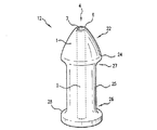
制限手段は、また、挿入可能部材に配置される当接部を含むことができる。例えば、制限手段は、個人の体腔への開口部(例えば、肛門括約筋)の内部または近くに配置可能であり、そこで1つまたは複数の当接面により支持される挿入可能部材を備えることができる。一実施形態においては、挿入可能部材の先端構造は、ほぼ円錐形の形状を有している。円錐の基部は、第1放射当接面を形成する。円錐の頂点は、個人の体腔の開口部への挿入可能部材の進入を開始するために用いられる。先端構造は、また、末端および近端を有する中央部分を含む。中央部分の近端が、円錐の基部に隣接して配置される。中央部分の近端は、円錐の基部の直径よりも小さい直径を有する。中央部分の末端は、その近端の直径よりも大きい直径を有し、第2放射当接面を形成する。一度挿入されると、腔の開口部は、第1および第2放射当接面の間に配置される。 The limiting means can also include an abutment disposed on the insertable member. For example, the restricting means can comprise an insertable member that can be placed within or near an opening to a body cavity of a person (eg, an anal sphincter), where it is supported by one or more abutment surfaces. . In one embodiment, the tip structure of the insertable member has a generally conical shape. The base of the cone forms a first radiation contact surface. The apex of the cone is used to initiate the insertion of the insertable member into the opening of the individual's body cavity. The tip structure also includes a central portion having a distal end and a proximal end. The proximal end of the central portion is located adjacent to the base of the cone. The proximal end of the central portion has a diameter that is smaller than the diameter of the base of the cone. The distal end of the central portion has a diameter that is larger than the diameter of its proximal end and forms a second radiation abutment surface. Once inserted, the cavity opening is disposed between the first and second radiation abutment surfaces.
制限手段は、また、軸に沿った第1円周を有する円筒ヘッドを備えることができる。挿入可能部材は、また、円筒ヘッドの基部の近くまたは隣の中央部分を含む。中央部分は、近端と末端を有する。前記末端部は、ほぼ円錐形の形状を有し、これによりほぼ平面の放射第1当接面を提供している。また、中央第1部分の近端に隣接して、第2当接面も存在する。 The restricting means can also comprise a cylindrical head having a first circumference along the axis. The insertable member also includes a central portion near or next to the base of the cylindrical head. The central portion has a proximal end and a distal end. The distal end has a generally conical shape, thereby providing a substantially planar radial first abutment surface. There is also a second abutment surface adjacent to the proximal end of the central first portion.
図面に、本発明の代替の実施形態、特に、個人からの排出物を受けるための器具、方法、システムおよびキットが示されている。さらに詳しくは、本発明は、排出物リザーバ(33)を備えることができる。リザーバ(33)の内部には、例えば診断または医療処置の間あるいは後に、個人の内腔から挿入可能部材(1)を通過してくる排出物を受けて集めることができる中空領域(34)を備えることができる。 In the drawings, alternative embodiments of the present invention are shown, in particular instruments, methods, systems and kits for receiving effluent from individuals. More particularly, the present invention may comprise an effluent reservoir (33). Inside the reservoir (33) is a hollow area (34) that can receive and collect effluent passing through the insertable member (1) from the individual's lumen, for example during or after a diagnostic or medical procedure. Can be provided.
図7Aは、排出物リザーバ(33)の正面図を示し、図7Bは、背面図を示す。一実施形態においては、排出物リザーバ(33)は、閉じられた底部(35)を有する中空領域(34)と、外周(38)が互いに固定された前壁および後壁(36,37)とを備えている。リザーバ(33)は、また、排出物リザーバの内部に排出物を入れ、または取り出すための1つまたは複数のポート(39)を備えることができる。リザーバ(33)は、さらに、排出物リザーバ(33)の内部(34)への、または内部からの媒体の運搬に使用するための1つまたは複数のポート(39)を含むことができる。代替の一実施形態においては、排出物リザーバ(33)は、折りたたみ可能な容器の形を取ることができる。他の実施形態においては、排出物リザーバは、硬質の容器を含むことができ、あるいは、折りたたみ可能な容器の形を取ることができる。 FIG. 7A shows a front view of the discharge reservoir (33) and FIG. 7B shows a rear view. In one embodiment, the effluent reservoir (33) comprises a hollow region (34) having a closed bottom (35), and a front wall and a rear wall (36, 37) with a perimeter (38) secured to each other. It has. The reservoir (33) can also include one or more ports (39) for placing or removing effluent within the effluent reservoir. The reservoir (33) may further include one or more ports (39) for use in transporting media to or from the interior (34) of the effluent reservoir (33). In an alternative embodiment, the discharge reservoir (33) can take the form of a collapsible container. In other embodiments, the discharge reservoir can include a rigid container or can take the form of a collapsible container.
本発明は、また、1つまたは複数のバリア(41)を備えることができる。1つまたは複数のバリア(41)は、1つまたは複数の位置に配置することができ、この位置は、排出物リザーバ(33)と、個人の排出物への接触から保護する領域との間のいずれかの導管とを含み、かつこれに限定されない。例えば、1つまたは複数のバリア(41)は、医療または診断処置に関連して使用されるコンポーネント、装置または機器に排出物が接触し、これを汚染することを防ぐために配置することができる。代替の一実施形態において、バリア(41)は、液体、固体、および気体でない粒子の通過に対して不透過性の材料の1つまたは複数の層を備えることができる。このようなバリアは、ウイルスおよびバクテリア、粘液および流体などの病原体の移動を著しく減少させることができる。代替の一実施形態においては、排出物バリア(41)は、0.1ミクロンの疎水性膜を含みかつこれに限定されない疎水性膜を備えることができ、抗ウイルスかつ抗菌のバリアを提供する。他の実施形態においては、調整可能なバリアは、クランプ、弁、止め栓、またはロッキングピンチクランプを含むことができる。 The present invention can also comprise one or more barriers (41). One or more barriers (41) can be placed in one or more locations, which are located between the waste reservoir (33) and the area that protects the person from contact with the waste. And any one of the following conduits: For example, one or more barriers (41) can be positioned to prevent effluent from contacting and contaminating components, devices or equipment used in connection with medical or diagnostic procedures. In an alternative embodiment, the barrier (41) may comprise one or more layers of material that is impermeable to the passage of liquid, solid, and non-gaseous particles . Such barriers can significantly reduce migration of pathogens such as viruses and bacteria, mucus and fluids. In an alternative embodiment, the effluent barrier (41) can comprise a hydrophobic membrane, including but not limited to a 0.1 micron hydrophobic membrane, providing an antiviral and antimicrobial barrier. In other embodiments, the adjustable barrier can include a clamp, a valve, a stopcock, or a locking pinch clamp.
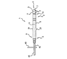
本発明においては、排出物リザーバ(33)または所望の医療機器を、1つまたは複数の導管(43)に結合することができる。導管は、いずれかの媒体または排出物を1つの場所から他へと運搬することが可能な中空領域(45)を含むことができる。本発明は、また、挿入可能部材を備えることができる。本発明の代替の一実施形態においては、挿入可能部材(1)は、前部(2)と後部(3)を有することができる。前部は、挿入可能部材(1)に支持された先端構造(4)を有する。先端構造は、個人の体腔の開口部への挿入可能部材(1)の進入を開始するために適合されている。先端構造(6)の頂点は、1つまたは複数の開口部(7)を有する。1つまたは複数の開口部は、頂点(6)の内部に配置された少なくとも1つの中空領域(5)に接続することができる。中空領域(5)は、先端構造(4)の長さに沿って伸ばすことができる。先端構造(4)は、先端構造(4)内に配置された中空領域(5)にそれぞれ接続された複数の開口部(7)を備えることができる。挿入可能部材(1)は、末端(9)と近端(10)を有する軸(8)を備えることができる。先端構造(4)は、軸(10)の近端またはその近くに配置することができる。軸(8)の内部は、1つまたは複数の中空領域(11)を備えることができる。1つまたは複数の中空領域は、軸(8)の長さに沿って伸ばすことができる。軸(8)の中空領域(11)は、先端構造(4)の中空領域(5)と直線にすることができ、これにより、挿入可能部材(2)の前部から後部(3)に伸びるチャネルを形成する。挿入可能部材(1)は、前記部材を、排出物リザーバ(33)あるいは医療機器またはそのいずれかのコンポーネントに通じる1つまたは複数の導管(43)に固定するための手段を備えることができる。 In the present invention, an effluent reservoir (33) or desired medical device can be coupled to one or more conduits (43). The conduit can include a hollow region (45) that can carry any medium or effluent from one location to another. The present invention can also include an insertable member. In an alternative embodiment of the invention, the insertable member (1) can have a front part (2) and a rear part (3). The front part has a tip structure (4) supported by the insertable member (1). The tip structure is adapted for initiating the insertion of the insertable member (1) into the opening of the individual's body cavity. The apex of the tip structure (6) has one or more openings (7). The one or more openings can be connected to at least one hollow region (5) located inside the apex (6). The hollow region (5) can extend along the length of the tip structure (4). The tip structure (4) can comprise a plurality of openings (7) each connected to a hollow region (5) disposed within the tip structure (4). The insertable member (1) can comprise a shaft (8) having a distal end (9) and a proximal end (10). The tip structure (4) can be located at or near the proximal end of the shaft (10). The interior of the shaft (8) can comprise one or more hollow regions (11). One or more hollow regions can extend along the length of the axis (8). The hollow region (11) of the shaft (8) can be straight with the hollow region (5) of the tip structure (4), thereby extending from the front of the insertable member (2) to the rear (3). Form a channel. The insertable member (1) may comprise means for securing the member to one or more conduits (43) leading to an effluent reservoir (33) or medical device or any component thereof.
本発明の挿入可能部材は、また、1つまたは複数の制限手段(12)を備えることができる。制限手段は、拡張可能構造(13)を備えることができる。一実施形態においては、軸(8)または先端構造(4)に、拡張可能構造(13)を設けることができる。代替の一実施形態においては、拡張可能構造(13)は、挿入可能部材(1)の軸(8)または先端構造(4)に支持された膨張可能な風船状の構造(14)の形を取ることができる。風船状の構造(14)は、挿入可能部材(1)の内部または外部に配置することができる膨張導管(15)に接続することができる。膨張導管(15)は、風船状構造内に導管(15)を通して気体または液体を注入することができるように、膨張ポンプ(16)に接続することができる。また、膨張導管(15)は、膨張導管(15)からの気体または液体の流れの漏れまたは通過を防止あるいは許可するための止め栓、バルブ、クランプまたは他のいずれかの手段に接続することができる。一実施形態においては、導管(15)は、膨張制御止め栓(17)と、膨張導管(15)を膨張ポンプ(16)のノズルに取り付けるための手段と、を備えることができる。一実施形態においては、拡張可能構造(13)は、E−Z−EM Flexi−Cuff(登録商標)シリコーンエラストマーリテンションカフ、または類似の器具である。この製品は、ニューヨーク州ウェストベリーのE−Z−EM,Inc.によって販売されている。 The insertable member of the present invention can also comprise one or more restricting means (12). The restricting means may comprise an expandable structure (13). In one embodiment, the shaft (8) or tip structure (4) can be provided with an expandable structure (13). In an alternative embodiment, the expandable structure (13) is in the form of an inflatable balloon-like structure (14) supported on the shaft (8) or tip structure (4) of the insertable member (1). Can be taken. The balloon-like structure (14) can be connected to an expansion conduit (15) that can be placed inside or outside the insertable member (1). The expansion conduit (15) can be connected to an expansion pump (16) so that gas or liquid can be injected through the conduit (15) into the balloon-like structure. The expansion conduit (15) may also be connected to stopcocks, valves, clamps or any other means for preventing or allowing leakage or passage of gas or liquid flow from the expansion conduit (15). it can. In one embodiment, the conduit (15) may comprise an expansion control stopcock (17) and means for attaching the expansion conduit (15) to the nozzle of the expansion pump (16). In one embodiment, the expandable structure (13) is an EZ-EM Flexi-Cuff® silicone elastomer retention cuff or similar device. This product is available from EZ-EM, Inc. of Westbury, NY. Sold by.
挿入可能部材(1)が、体腔の開口部を通して挿入されると、軸(8)または先端構造(4)に支持された風船状の構造(14)を、通常の平らな状態(19)から膨らんだ風船状のドーナツ(20)に膨張させて、望ましくない挿入可能部材(1)の動きを防止することができる。 When the insertable member (1) is inserted through the opening of the body cavity, the balloon-like structure (14) supported by the shaft (8) or the tip structure (4) is removed from the normal flat state (19). An inflated balloon-like donut (20) can be inflated to prevent unwanted movement of the insertable member (1).
制限手段(12)は、また、挿入可能部材(1)またはその近傍に配置された当接部を備えることができる。例えば、制限手段(12)は、ほぼ円錐状の形状(22)を有することができる。円錐(22)の基部は、第1放射当接面(24)を形成する。挿入可能部材(1)は、また、末端(26)と近端(27)を有する中央部分(25)を備える。中央部分(25)の近端(27)は、先端構造(4)の基部に隣接して配置される。中央部分(25)の近端(27)は、先端構造(4)の基部の直径よりも小さい直径を有する。中央部分(25)の末端は(26)は、その近端(27)の直径よりも大きな直径を持つことができ、これにより第2放射当接面を形成する。一度挿入されると、腔の入口またはその周囲が、第1および第2放射当接面(24,28)の間に位置し、挿入可能部材(1)を個人の体腔の内部に固定する。 The limiting means (12) can also comprise an abutment located at or near the insertable member (1). For example, the limiting means (12) can have a substantially conical shape (22). The base of the cone (22) forms a first radiation contact surface (24). The insertable member (1) also comprises a central portion (25) having a distal end (26) and a proximal end (27). The proximal end (27) of the central portion (25) is disposed adjacent to the base of the tip structure (4). The proximal end (27) of the central portion (25) has a diameter that is smaller than the diameter of the base of the tip structure (4) . The distal end (26) of the central portion (25) can have a diameter that is larger than the diameter of its proximal end (27), thereby forming a second radiating abutment surface. Once inserted, the entrance of the cavity or its periphery is located between the first and second radiation abutment surfaces (24, 28) to secure the insertable member (1) within the body cavity of the individual.
制限手段(12)は、また、軸に沿った第1円周を有する円筒ヘッド(29)を備えることができる。挿入可能部材(1)は、また、末端部(26)を有する中央部分(25)を備える。挿入可能部材(1)は、また、ほぼ円錐状の形状(32)を有する近端部(27)も含み、これにより、近端部(27)またはその近くにほぼ平面の放射第1当接面(24)を提供している。また、中央部分(25)の末端(26)に隣接した第2当接面(28)も存在する。 The limiting means (12) can also comprise a cylindrical head (29) having a first circumference along the axis. The insertable member (1) also comprises a central portion (25) having a distal end (26). The insertable member (1) also includes a proximal end (27) having a generally conical shape (32), whereby a substantially planar radial first abutment at or near the proximal end (27). A surface (24) is provided. There is also a second abutment surface (28) adjacent to the end (26) of the central portion (25).
図14〜図17を参照すると、吹込み機器またはユニットと共に使用する使い捨て器具が示されている。器具(50)は、自動吹込みユニット(51)と共に使用するためのものである。本発明のチュービング器具との使用に適した吹込みユニットは、E−Z−EM PROTOCO2LTM Colon Insufflatorまたは類似の装置を含み、かつこれに限定されない。この製品は、ニューヨーク州ウェストベリーのE−Z−EM,Inc.によって販売されている。このような器具(50)は、吹込みユニット(51)と共に使用すると、個人から直腸を通して排出されるいかなる排出物によるユニットの汚染も防ぐ。もう一つの実施形態においては、器具(50)は、無菌の形態で供給される。他の実施形態においては、本発明の1つまたは複数のコンポーネントが、ラテックスを含まない形態で提供される。器具(50)は、単一の患者への使用に適している。 Referring to FIGS. 14-17, a disposable device for use with a blowing device or unit is shown. The instrument (50) is for use with an automatic blowing unit (51). Blow units suitable for use with the tubing device of the present invention include, but are not limited to, EZ-EM PROTOCO 2 L ™ Colon Insufflator or similar devices. This product is available from EZ-EM, Inc. of Westbury, NY. Sold by. Such a device (50), when used with the insufflation unit (51), prevents contamination of the unit with any effluent discharged from the individual through the rectum. In another embodiment , the instrument (50) is supplied in a sterile form. In other embodiments, one or more components of the present invention are provided in a latex free form. The instrument (50) is suitable for use on a single patient.
器具(50)は、チューブ(52)を提供する。チューブ(52)は、ビニールまたは類似のプラスチックを含むフレキシブルチューブを含むことができ、またこれに限定されない。器具(50)は、また、チューブ(52)の末端に位置する単一ルーメンの挿入可能部材(1)を含む。挿入可能部材(1)は、個人の直腸に挿入可能である。一実施形態においては、単一ルーメンの挿入可能部材は、E−Z−EMカタログNo.8816,E−Z−EM Flexi−Tip(登録商標)、または任意の均等物である。この製品も、ニューヨーク州ウェストベリーのE−Z−EMによって販売されている。他の実施形態においては、先端構造(4)は、ディップ成形されたビニル先端である。成形ビニル先端は、ロッキングピンチクランプ(49)に一体的に接続することができる。 The instrument (50) provides a tube (52). The tube (52) can include, but is not limited to, a flexible tube comprising vinyl or similar plastic. The instrument (50) also includes a single lumen insertable member (1) located at the distal end of the tube (52). The insertable member (1) can be inserted into an individual's rectum. In one embodiment, the single lumen insertable member is an EZ-EM catalog no. 8816, EZ-EM Flexi-Tip (R), or any equivalent. This product is also sold by EZ-EM of Westbury, New York. In other embodiments, the tip structure (4) is a dip molded vinyl tip. The molded vinyl tip can be integrally connected to a locking pinch clamp (49).
クランプ(49)は、挿入可能部材(1)の近くのチュービング(52)に取り付けられている。一実施形態においては、クランプ(49)は、チュービング(52)に取り付けられたスライドクランプである。クランプ(49)は、単独で、または排出物リザーバ(33)に連動させて使用することができ、処置の期間の間または後に個人から排出されるいかなる大便/排出物も集める。処置の終わりに、クランプ(49)を作動させることにより、排出された大便/排出物は排出物リザーバ(33)の中に収容され、散乱を最小化し、排出物の処分を容易にする。 The clamp (49) is attached to the tubing (52) near the insertable member (1). In one embodiment, the clamp (49) is a slide clamp attached to the tubing (52). The clamp (49) can be used alone or in conjunction with the effluent reservoir (33) to collect any stool / effluent discharged from the individual during or after the treatment period. By activating the clamp (49) at the end of the procedure, the excreted stool / effluent is contained in the waste reservoir (33), minimizing scatter and facilitating disposal of the waste.
排出物リザーバ(33)は、吹込み処置の間に患者から排出される大便/排出物の保持に使用される。排出物リザーバ(33)は、クランプ(49)の近くに配置することができる。一実施形態においては、排出物リザーバ(33)は柔軟な容器であり、好ましくは折りたたみ可能なポリビニール袋である。排出物リザーバ(33)は、チュービング(52)を通るCO2ガス流れの直接ライン上にある。排出物リザーバ(33)がチュービング(52)を通る吹込みガス流れの直接ライン上にあるので、処置の開始と共に排出される残りの大便はいずれも、このリザーバ(33)に移動して集まり、これにより、処置の間に排出物の大きな柱が吹込みガスの通路を塞ぐことを防止する。排出された大便が排出物リザーバ(33)内にある状態で、空電空式吹込み器または手動吹込み器からのガスが、チュービング(52)を通って自由に患者に移動することができる。また、膨張ガスは、自由に双方向に流れることができ、これにより電空式吹込み器の圧力感知特性を活用することを可能にする。これは、直腸を一定のユーザ設定圧力で自動的に膨張させることを可能にする。 The discharge reservoir (33) is used to hold stool / discharge discharged from the patient during the insufflation procedure. The discharge reservoir (33) can be located near the clamp (49). In one embodiment, the discharge reservoir (33) is a flexible container, preferably a collapsible polyvinyl bag. The exhaust reservoir (33) is on the direct line of CO 2 gas flow through the tubing (52). Since the discharge reservoir (33) is on the direct line of insufflation gas flow through the tubing (52), any remaining stool discharged at the start of the procedure will move to this reservoir (33) and collect, This prevents large columns of effluent from blocking the insufflation gas passage during the procedure. With the discharged stool in the discharge reservoir (33), the gas from the electropneumatic or manual blower can move freely through the tubing (52) to the patient. . Also, the inflation gas can freely flow in both directions, thereby making it possible to exploit the pressure sensing characteristics of the electropneumatic blower. This allows the rectum to be automatically inflated with a constant user set pressure.
一実施形態においては、袋が柔軟で折りたためるように、排出物リザーバ(33)は、軟質のプラスチック(例えばビニール)を含む。排出物リザーバ(33)は、約20cc〜約150cc、または80cc、60cc、あるいは120ccもしくは140ccを含みかつこれらに限定されない容積を有する。排出物リザーバ(33)は、また、その上面に一体化された2つのチュービング接続ポート(39)を含む。一実施形態においては、接続ポート(39)は、市販のコルダーロッキング医療チュービング接続、または類似の器具である。代替の実施形態においては、排出物リザーバ(33)は、プラスチックバイアルなどの硬質の容器を含む。硬質の容器に対する柔軟な袋の主な利点は、しかしながら、製造、保管、運送、使用および続く処置後の処理の間に取り扱いを必要とする袋の実質体積が小さいことである。 In one embodiment, the discharge reservoir (33) comprises a soft plastic (eg, vinyl) so that the bag is flexible and folds. The discharge reservoir (33) has a volume that includes, but is not limited to, about 20cc to about 150cc, or 80cc, 60cc, or 120cc or 140cc. The discharge reservoir (33) also includes two tubing connection ports (39) integrated on its upper surface. In one embodiment, the connection port (39) is a commercially available corder-locking medical tubing connection or similar device. In an alternative embodiment, the discharge reservoir (33) includes a rigid container such as a plastic vial. The main advantage of a flexible bag over a rigid container, however, is that the substantial volume of the bag that requires handling during manufacturing, storage, transportation, use and subsequent post-treatment processing is small.
一実施形態においては、排出物リザーバ(33)は、診断処置の間、患者の高さより下に保持される。あるいは、排出物リザーバ(33)は、患者が器具に繋がれたままで、患者の高さよりも高く上げることもできる。これらの状況下では、スライドクランプ(49)を完全に閉じて、挿入可能部材を通じた排出物/大便の個人の腔への再入を防ぐことが有益であろう。 In one embodiment, the effluent reservoir (33) is held below the patient's height during the diagnostic procedure. Alternatively, the discharge reservoir (33) can be raised above the height of the patient while the patient remains connected to the instrument. Under these circumstances, it may be beneficial to fully close the slide clamp (49) to prevent re-entry of the effluent / stool into the individual's cavity through the insertable member.
バリア(41)は、チュービング(52)のライン上に位置する。バリア(41)は、排出物リザーバ(33)の隣、または近くに配置することができる。一実施形態においては、バリアをフィルタとすることができる。ここで、使用が適切なフィルタは、吹込み機器の汚染を防ぐ抗菌かつ抗ウイルスのバリアの提供に適した任意のフィルタを含み、かつこれに限定されない。一実施形態においては、バリア(41)は疎水性フィルタであり、特に0.1ミクロンの疎水性膜である。排出物リザーバ(33)に近い疎水性フィルタを利用することにより、処置の間に患者から排出されるウイルス性および/またはバクテリア性の物質はいずれも、排出物リザーバ(33)に収容される。 The barrier (41) is located on the tubing (52) line. The barrier (41) can be placed next to or near the effluent reservoir (33). In one embodiment, the barrier can be a filter. Here, filters suitable for use include, but are not limited to, any filter suitable for providing an antibacterial and antiviral barrier that prevents contamination of the blowing device. In one embodiment, the barrier (41) is a hydrophobic filter, in particular a 0.1 micron hydrophobic membrane. By utilizing a hydrophobic filter close to the drain reservoir (33), any viral and / or bacterial substances drained from the patient during the procedure are contained in the drain reservoir (33).
チュービングセット(52)は、接続(55)において吹込み器に取り付けられる。一実施形態においては、接続(55)は市販のコルダーロッキング医療チュービング接続、または類似の器具である。一実施形態においては、チュービング(52)は、自動CO2ガス吹込み器に接続される。 Tubing set (52) is attached to the blower at connection (55). In one embodiment, connection (55) is a commercially available corder-locking medical tubing connection or similar device. In one embodiment, tubing (52) is connected to the automatic CO 2 gas blowing device.
挿入可能部材(1)は、診断処置の間に結腸膨張のレベルを維持するための拡張可能構造(13)を含む。拡張可能構造(13)は、膨張すると、診断処置の間のガスの漏れを防止する。これは、現在使われているハンドバルブ膨張方法からの改善を表わしている。ガスが診断処置の間に直腸腔から漏れる可能性があるためである。ここで、使用に適した風船は、EZ−EM Balloon Inflators Cat.No.9529[REF 9529EU]を含み、かつこれに限定されない。一実施形態においては、拡張可能構造(13)は、約1cc〜約100ccの空気で膨張される。 The insertable member (1) includes an expandable structure (13) for maintaining the level of colonic expansion during the diagnostic procedure. The expandable structure (13), when inflated, prevents gas leakage during the diagnostic procedure. This represents an improvement over the currently used hand valve inflation method. This is because gas can escape from the rectal cavity during diagnostic procedures. Here, balloons suitable for use are EZ-EM Balloon Inflators Cat. No. Including but not limited to 9529 [REF 9529 EU]. In one embodiment, the expandable structure (13) is inflated with about 1 cc to about 100 cc of air.
一実施形態においては、カート(60)が、本発明が用いられる環境に関わる人的要因に適合するように設計されている。主要な機能は、CTまたは結腸内視鏡室内の移動式プラットフォーム上に、吹込みユニットおよびCO2供給シリンダを支持することである。その上、カート(60)は、処置の間に本発明の排出物トラップを垂直に維持するための取付け具を提供する。これは、トラップの底にある排出されたいずれの液体排出物/大便も、ガスルーメンから離して局所的に制限することにより、その効果を最大化する。また、排出物リザーバの縦の高さを、吹込み器および検査台より低く維持する。排出物リザーバを、吹込み器および個人の両方より低い位置に固定することで、リザーバへの排出物の集積を重力によって促進する。 In one embodiment, the cart (60) is designed to meet the human factors involved in the environment in which the present invention is used. Main functions, on CT or colonoscope indoor mobile platform is to support blowing unit and CO 2 supply cylinders. In addition, the cart (60) provides a fixture for keeping the effluent trap of the present invention vertical during the procedure. This maximizes the effectiveness of any discharged liquid stool / stool at the bottom of the trap by locally limiting it away from the gas lumen. Also, the vertical height of the discharge reservoir is kept lower than the blower and the inspection table. By fixing the waste reservoir at a lower position than both the insufflator and the individual, the accumulation of the waste in the reservoir is facilitated by gravity.
一実施形態においては、吹込み器(51)は、自動吹込みユニットである。ここでの使用に適した自動吹込みユニットは、気体を結腸内に送り込むための任意の電子装置を含み、かつこれに限定されない。一実施形態においては、ユニットは、電空式二酸化炭素吹込み器であり、制御インターフェイスで以下のパラメータを指定することにより、CO2を患者の結腸に送って膨張させるようになっている。患者内にセットされた使い捨てチューブの浣腸先端を直腸に挿入する場合、適切なCO2の膨張圧は、0〜25mmHgを含むことができる。CO2の設定流れ速度は、約1〜20L/mmを含むことができ、設定圧は約10mmHg〜約50mmHgとし、好ましくは、それぞれ約3〜6L/mmおよび20〜30mmHgとする。 In one embodiment, the blower (51) is an automatic blowing unit. Autoblowing units suitable for use herein include, but are not limited to, any electronic device for injecting gas into the colon. In one embodiment, the unit is an electropneumatic carbon dioxide insufflator that is adapted to deliver CO 2 to the patient's colon for inflation by specifying the following parameters at the control interface. When the enema tip of a disposable tube set in a patient is inserted into the rectum, a suitable CO 2 inflation pressure can include 0-25 mmHg. The set flow rate of CO 2 can include about 1-20 L / mm, and the set pressure is about 10 mmHg to about 50 mmHg, preferably about 3-6 L / mm and 20-30 mmHg, respectively.
一実施形態においては、本発明の吹込みシステムは、E−Z−EM PROTOCO2LTM ADMINISTRATION SET、または類似のシステムであり、CT結腸検査、あるいは結腸膨張を必要とする他のいずれかの診断処置を目的として、膨張媒体としてのCO2を患者の結腸に送り込み、その調整を行うために使用される。PROTOCO2L吹込み器ユニットは、現在市場に出ている腹腔鏡吹込み技術に基づいている。この吹込みユニットは、ソフトウェア制御された電気機械システムであり、供給シリンダから患者へのCO2の流れを正確に圧力調整し測定する。PROTOCO2L ADMINISTRATION SETは、8フィートのビニールチュービングと、2つの風船膨張器と、プラスチックチュービングクランプと、Flexi−Cuffシリコーンエラストマーリテンションカフ付きのFlexi−Tipと、0.1マイクロメータ非疎水性フィルタと、100mL排出物集積容器と、PROTOCO2L Colon Insufflatorへのコネクタとを含む。システムは、患者のアレルギー反応を防ぐために、ラテックスを含まない形態で好適に提供される。あるいは、上記のシステムは、ニューヨーク州ウェストベリーのE−Z−EM,Inc.により販売されているE−Z−EMハードバルブまたはE−Z−EM E−Z−Flat器具を含む、いずれかの空気式手動吹込み器と共に用いることもできる。 In one embodiment, the insufflation system of the present invention is an EZ-EM PROTOCO 2 L ™ ADMINISTRATION SET, or similar system, CT colon examination, or any other diagnosis that requires colonic dilatation For treatment purposes, CO 2 as an inflation medium is delivered to the patient's colon and used to make adjustments. The PROTOCO 2 L inflator unit is based on laparoscopic insufflation technology currently on the market. The insufflation unit is a software controlled electromechanical system that accurately regulates and measures the flow of CO 2 from the supply cylinder to the patient. PROTOCO 2 L ADMINISTRATION SET is an 8 foot vinyl tubing, two balloon inflaters, a plastic tubing clamp, a Flexi-Tip with Flexi-Cuff silicone elastomer retention cuff, a 0.1 micrometer non-hydrophobic filter, , 100 mL effluent collection container and connector to PROTOCO 2 L Colon Insufflator. The system is suitably provided in a latex-free form to prevent patient allergic reactions. Alternatively, the system described above is available from EZ-EM, Inc. of Westbury, NY. Can also be used with any pneumatic manual blower, including EZ-EM hard valves or EZ-EM EZ-Flat instruments sold by
本発明は、さらに、医療または診断処置の前または間に媒体を投与している、個人の体腔の開口部から排出される排出物を集める方法に関する。この方法は、1つまたは複数の以下のステップを含む。(1)排出物リザーバを挿入可能部材あるいは医療または診断処置の実行に必要な他の機器に接続し、(2)挿入可能部材を、個人の体腔の開口部を通して挿入し、(3)挿入可能部材が個人の腔に挿入されている間に医療または診断処置を行い、(4)処置の間または後に個人の腔の開口部を通過する排出物を、排出物リザーバに集め、(4)必要に応じて、排出物リザーバの高さを調整して、排出物リザーバへの排出物の通過を促進し、(5)排出物リザーバを挿入可能部材または機器から取り外し、(6)取扱いの際に排出物が排出物リザーバから漏れることを防止するために、1つまたは複数のクランプを結合する。 The invention further relates to a method for collecting effluent discharged from an opening in a body cavity of an individual administering a medium prior to or during a medical or diagnostic procedure. The method includes one or more of the following steps. (1) connect the effluent reservoir to an insertable member or other equipment necessary to perform a medical or diagnostic procedure, (2) insert the insertable member through an opening in the body cavity of an individual, and (3) insert Perform medical or diagnostic procedures while the member is inserted into the individual's cavity; (4) collect the effluent passing through the opening of the individual's cavity during or after the procedure in the effluent reservoir; (4) required The height of the discharge reservoir is adjusted accordingly to facilitate passage of the discharge into the discharge reservoir, (5) the discharge reservoir is removed from the insertable member or device, and (6) during handling. One or more clamps are coupled to prevent discharge from leaking out of the discharge reservoir.
図15は、排出物トラップがアクセサリーカートでなく自動吹込み器(68)に取り付けられた本発明の実施形態を示している。この図は、角度を付けて上部に取り付けられ、患者より下の縦位置に配置されている場合でも作業者が制御できるようにした制御パネル(70)を示している。このような配置の利点は、患者へのCO2の投与の前に、排出物トラップの存在を検出し得るようにした、超音波または電子光学センサを含みかつこれに限定されないセンサ手段(71)が設けられていることである。一実施形態においては、センサは、排出物リザーバの外面に配置することができる。このようなセンサの目的は、2つある。第1に、意図されない器具の操作を防止することである。第2に、感知のための構成を使用して、排出物リザーバの吹込み機器への接続が正しいことを確認できることである。 FIG. 15 shows an embodiment of the invention in which the emissions trap is attached to an automatic blower (68) rather than an accessory cart. This figure shows the control panel (70) attached to the top at an angle so that the operator can control it even when placed in a vertical position below the patient. The advantages of such an arrangement are sensor means (71) including but not limited to ultrasonic or electro-optic sensors, which can detect the presence of an effluent trap prior to administration of CO 2 to the patient. Is provided. In one embodiment, the sensor can be located on the outer surface of the effluent reservoir. There are two purposes for such a sensor. The first is to prevent unintended instrument operation. Second, the sensing configuration can be used to confirm the correct connection of the discharge reservoir to the blowing device.
図16は、排出物トラップがアクセサリーカートでなく自動吹込み器(68)に取り付けられた本発明の実施形態を再び示している。この図では、センサ(71)および(72)は、1つまたは複数のセンサ手段を含むことができる。これらのセンサは、排出物トラップおよび非疎水性フィルタの存在をそれぞれ検出するために使用される。これらのセンサは、図15に示した排出物トラップに用いられたセンサの目的と同一の目的を持っている。その上、医療用非疎水性フィルタが、通常、硬質のプラスチックのハウジングに取り付けられているため、ここで排出物トラップを支持している吹込み器の前面は、非疎水性フィルタの形状を受け入れるための形状的機能を含むことができる。このフィルタの取り付け構成は、センサ(電子光学式)との関連において、固有の形状特性を有するフィルタを収容するように設計することができる。同様に、図16のフィルタ電子光学センサ(72)の配置は、膜の上流/末端側に置くことができる。投与セットの材質特性と共に、電子光学センサの特性は、センサが、故障、すなわちフィルタ膜を横切る液体のブリーチも感知できるように調整することができる。この同一の目的を果たす代替の感知技術は、超音波である。 FIG. 16 again shows an embodiment of the present invention in which the emissions trap is attached to an automatic blower (68) rather than an accessory cart. In this figure, sensors (71) and (72) can include one or more sensor means. These sensors are used to detect the presence of effluent traps and non-hydrophobic filters, respectively. These sensors have the same purpose as that of the sensor used in the emission trap shown in FIG. In addition, since the medical non-hydrophobic filter is usually attached to a rigid plastic housing, the front of the blower supporting the effluent trap here accepts the shape of the non-hydrophobic filter Can include geometric features. This filter mounting configuration can be designed to accommodate filters having unique shape characteristics in the context of sensors (electro-optical). Similarly, the arrangement of the filter electro-optic sensor (72) of FIG. 16 can be placed upstream / terminal side of the membrane. Along with the material properties of the dosing set, the properties of the electro-optic sensor can be adjusted so that the sensor can also detect faults, i.e. breach of liquid across the filter membrane. An alternative sensing technique that serves this same purpose is ultrasound.
図17は、多孔フィルタ媒体が、電空式吹込み器のベントポートに取り付けられた本発明の実施形態を示している。このような媒体は、患者を元とする悪臭ガスが、処置の過程で周りの病室の空気に漏れ出すことを無くす、あるいは最小化するために用いることができる活性炭または他の洗浄媒体を含むことができる。 FIG. 17 illustrates an embodiment of the present invention in which a porous filter media is attached to the vent port of an electropneumatic blower. Such media include activated carbon or other cleaning media that can be used to prevent or minimize patient-based malodorous gases from leaking into the surrounding room air during the procedure. Can do.
本明細書の図面および添付物は、図解のみを目的として提示されている。これらは、本発明の範囲の限定を意図するものではない。さらに、当業者には、本明細書に記載された実施形態の様々な変更および修正が明らかとなることが理解されるべきである。このような変更および修正は、本発明の要旨および範囲から逸脱することなく、また、本発明に伴う利点を減少させることなく行うことができる。したがって、このような変更および修正を、添付の特許請求の範囲に含むことが意図される。また、本発明は、本明細書に記載される要素を適切に包含することができ、または、本明細書に記載される要素で構成され、あるいは、本質的に構成される。さらに、本明細書に例示的に開示される本発明は、本明細書に詳細に記載されている、または、記載されていないいずれの要素が無くとも、適切に実施することができる。 The drawings and attachments herein are presented for illustrative purposes only. These are not intended to limit the scope of the invention. Further, it should be understood by those skilled in the art that various changes and modifications to the embodiments described herein will be apparent. Such changes and modifications can be made without departing from the spirit and scope of the present invention and without diminishing its attendant advantages. Accordingly, such changes and modifications are intended to be included within the scope of the appended claims. In addition, the present invention can appropriately include the elements described in the present specification, or is composed of, or essentially consists of, the elements described in the present specification. Further, the present invention disclosed by way of example herein can be suitably practiced without any of the elements described in detail or not described herein.
Claims (35)
底部、上部、後壁および前壁を有すると共に、前記リザーバの内部に通じる2以上の開口部を含むリザーバを備え、
少なくとも1つの前記開口部は、医療または診断機器とのみ接続すると共に、少なくとも1つの前記開口部は、前記体腔とのみ接続し、前記体腔から排出された排出物は、リザーバの中に入り、接続された前記医療または診断機器から排出されたガスは、前記体腔に入る前に前記リザーバの内部を経由して、排出物と反対方向に通過することを特徴とする器具。In a device suitable for collecting effluent from an opening in a person's body cavity,
A reservoir having a bottom, a top, a rear wall and a front wall and including two or more openings leading to the interior of the reservoir;
At least one of the openings is connected only to a medical or diagnostic device, and at least one of the openings is connected only to the body cavity, and the discharge discharged from the body cavity enters the reservoir and is connected instrument gas discharged from the medical or diagnostic equipment, via the interior of the reservoir prior to entering the body cavity, characterized by the Turkey to pass in the opposite direction to the effluent.
(i)近端と末端を有する第1導管と、
(ii)診断前あるいは診断中に個人の結腸から排出物を集めるのに適したリザーバであって、前記リザーバの内部は、前記第1導管の前記末端と接続され、前記個人の肛門を通過する排出物を、前記リザーバ内に集められるようにしたリザーバと、
(iii)個人の肛門からの排出物の排出と吹込み装置から個人の肛門へのガスの導入の両方を許容する、個人の肛門への挿入に適した挿入可能部材であって、その挿入可能部材は前部と後部を有し、その前部から後部に伸びる単一のチャネルを有し、その後部は、前記第1導管の前記近端と接続される挿入可能部材と、
(iv)近端および末端を有する第2導管であって、前記近端は、前記リザーバの内部に接続され、前記末端は、前記吹き込み装置との接続に適合し、前記吹込み装置から排出されたガスが、前記吹き込み装置から前記第2導管へと通り、前記リザーバの内部と、前記第1導管と、前記挿入可能部材とを通過して前記個人の肛門に入るようになっていて、個人の肛門から排出される排出物が前記挿入可能部材および第1導管を通じて前記リザーバに入り、前記吹き込み装置からのガスが診断前あるいは診断中に前記リザーバを経由して通過する第2導管と、
(v)前記第2の導管に配置された1以上のバリアであって、診断前あるいは診断中に排出物が前記吹き込み装置に接触するのを防ぐのに適したバリアと、を備えることを特徴とする器具。In a device suitable for use to inflate an individual's colon before or during diagnosis,
(I) a first conduit having a proximal end and a distal end;
(Ii) a reservoir suitable for collecting effluent from the individual's colon before or during diagnosis, the interior of the reservoir being connected to the end of the first conduit and passing through the individual's anus A reservoir adapted to collect waste in the reservoir;
(Iii) An insertable member suitable for insertion into the individual's anus that allows both the discharge of the discharge from the individual's anus and the introduction of gas from the insufflation device into the individual's anus The member has a front portion and a rear portion and has a single channel extending from the front portion to the rear portion, the rear portion being an insertable member connected to the proximal end of the first conduit;
(Iv) a second conduit having a proximal end and a distal end, the proximal end being connected to the interior of the reservoir, the distal end being adapted for connection with the blowing device and being discharged from the blowing device Gas passes from the insufflation device to the second conduit, passes through the interior of the reservoir, the first conduit, and the insertable member into the individual's anus, A second conduit through which gas discharged from the anus enters the reservoir through the insertable member and a first conduit, and gas from the insufflation device passes through the reservoir before or during diagnosis;
(V) a pre SL 1 or more barrier disposed in the second conduit, in that it comprises a barrier adapted to prevent emissions into the diagnosis before or diagnosis of contacting the injectors A featured instrument.
上端および下端を有する固体で膨張しない構造の、伸びた中空の挿入可能部材であって、前記上端は、上開口部を含み、前記下端は、下開口部を有し、前記上開口部および下開口部は、前記上開口部から前記下開口部への排出物の通過および前記下開口部から前記上開口部への吹き込み装置からのガスの導入に十分な断面の中空領域を有するチャネル(流路)を介して動作可能に結合されている挿入可能部材と、
前記上開口部に近接した前記挿入可能部材の前記上端に固定され、これを囲んだ環状の拡張可能部材であって、前記拡張可能部材は、外向きに拡張し、前記挿入可能部材の周囲を前記上開口部に近接して囲み、前記体腔の開口部を密閉して、排出物が中空の挿入可能部材のみを通して前記体腔から外へ出るように構成され、前記拡張可能部材が前記体腔の開口部内に配置された後にこれを膨張させるための膨張導管を含む拡張可能部材と、
排出物が前記体腔から前記挿入可能部材を通じて前記リザーバに入り、診断の前あるいは診断中に吹き込み装置からのガスが前記リザーバを経由して通り前記体腔に入るように前記挿入可能部材の下端および吹き込み装置の両方に固定されると共に前記挿入可能部材と前記吹き込み装置の間に配置された排出物リザーバと、を含むことを特徴とする器具。In a device for collecting effluent from a body cavity through an opening in the body cavity,
Structure does not expand in solid having an upper end and a lower end, a hollow insert member extending, the upper end includes an upper opening, the lower end, have a lower opening, the upper opening and the lower The opening is a channel (flow channel) having a cross-sectional hollow area sufficient for the passage of discharge from the upper opening to the lower opening and the introduction of gas from the blowing device from the lower opening to the upper opening. An insertable member operatively coupled via a path) ;
An annular expandable member fixed to and surrounding the upper end of the insertable member proximate the upper opening, the expandable member extending outwardly and surrounding the insertable member enclose in proximity to the upper opening, to seal the opening of the body cavity is configured such effluent exits from the body cavity through only the hollow of the insertable member into the outer, open the expandable member of said cavity An expandable member including an inflation conduit for inflating it after being placed in the section;
Effluent enters the reservoir through the insertion member from the body cavity, the lower end of the insertable member as the gas from the device blowing the previous diagnosis or during diagnosis enters through the body cavity via the front SL reservoir and instrument, characterized in that it comprises a blowing device arranged effluent reservoir between both fixed to Rutotomoni the insertable member and the blowing apparatus, the.
底部、上部、後壁および前壁を有するリザーバであって、前記リザーバは、前記リザーバの内部に通じる2以上の開口部を有し、
前記リザーバは、吹き込み装置との接続を形成するための少なくとも1つの接続コンポーネントおよび挿入可能部材との接続を形成するための少なくとも1つの接続コンポーネントを有し、ガスが前記体腔へ投与可能な構造となり、同時に、前記リザーバ内の排出物を収集し、投与されたガスが前記体腔に入る前に前記リザーバの内部を経由して、前記リザーバの中に収集されている排出物とは反対方向に向かって通過するように、前記リザーバは、前記吹き込み装置と前記体腔との間に位置する構成となることを特徴とする器具。 In an instrument for collecting effluent from an individual's internal body cavity during or after a medical or diagnostic procedure involving administration of a gas vehicle to the body cavity
A reservoir having a bottom, a top, a rear wall and a front wall, the reservoir having two or more openings leading to the interior of the reservoir;
The reservoir has at least one connection component for forming a connection with the insufflation device and at least one connection component for forming a connection with the insertable member, the structure allowing gas to be administered to the body cavity next, at the same time, collect the effluent in the reservoir, the direction opposite to the dosing gas is via the interior of the reservoir prior to entering the body cavity, effluent being collected in said reservoir The reservoir is configured to be positioned between the insufflation device and the body cavity so as to pass toward the body .
近端と末端を有する第1導管と、前部と後部を有する単一ルーメン挿入可能部材とを備え、
前記挿入可能部材の後部は、前記第1導管の近端に配置され、前記前部は、体腔開口部に挿入可能であり、前記挿入可能部材の前記後部の近くに配置されたクランプと、前記体腔からの排出物を集めるための排出物リザーバと、近端および末端を有し、その面に配置される少なくとも1つの疎水性のバリアを有する第2導管と、ガスを投与するのに適した医療または診断機器に前記第2導管の前記末端を接続するための少なくとも1つの接続コンポーネント、および前記リザーバに前記第2導管の前記近端を接続するための少なくとも1つの接続コンポーネントとを備え、
前記挿入可能部材、前記第1導管、前記リザーバおよび前記第2導管は、前記体腔から排出される排出物が前記挿入可能部材、第1導管を通じて前記リザーバに入り、接続された前記吹き込み装置から排出されたガスは、前記吹き込み装置から、第2導管、前記リザーバの内部、第1導管、前記挿入可能部材を通じて前記体腔に入る構成であることを特徴とする器具。In instruments for use in conjunction with medical or diagnostic equipment,
A first conduit having a proximal end and a distal end; and a single lumen insertable member having a front portion and a rear portion;
A rear portion of the insertable member is disposed at a proximal end of the first conduit; the front portion is insertable into a body cavity opening; and a clamp disposed near the rear portion of the insertable member; A discharge reservoir for collecting discharge from the body cavity, a second conduit having a proximal end and a distal end and having at least one hydrophobic barrier disposed on its face, suitable for administering gas At least one connection component for connecting the distal end of the second conduit to a medical or diagnostic instrument, and at least one connection component for connecting the proximal end of the second conduit to the reservoir ;
The insertable member, the first conduit, the reservoir, and the second conduit are configured such that waste discharged from the body cavity enters the reservoir through the insertable member, first conduit and is discharged from the connected blowing device. The gas is configured to enter the body cavity from the blowing device through the second conduit, the interior of the reservoir, the first conduit, and the insertable member.
約8フィートのビニールチュービングと、エラストマー風船を膨張させるための1つまたは複数の風船膨張器と、1つまたは複数のプラスチックチュービングクランプと、1つまたは複数の浣腸先端を備える単一ルーメン挿入可能部材と、1つまたは複数のシリコーンエラストマー風船と、1つまたは複数の0.1マクロメートル疎水性フィルタと、少なくとも1つの排出物リザーバと、接続された際に、体腔から排出された排出物が、前記挿入可能部材を通り、次にビニールチュービングの第1区域を通って前記リザーバに入り、前記吹き込みユニットから排出されたガスが前記体腔に入る前に、前記リザーバの内部を通過するように前記ビニールチュービングを自動吹き込みユニットに接続するための1つまたは複数のチュービングコネクタとを含むことを特徴とするキット。In kits for use with automatic or manual blowing units
Single lumen insertable member comprising about 8 feet of vinyl tubing, one or more balloon inflaters for inflating an elastomeric balloon , one or more plastic tubing clamps, and one or more enema tips When one or a plurality of silicone elastomer balloons, one or a plurality of 0.1 macros meters hydrophobic filter, and one effluent reservoir even without low, when connected, exudates discharged from the body cavity Passes through the insertable member and then through the first section of vinyl tubing into the reservoir and allows the gas exhausted from the blowing unit to pass through the interior of the reservoir before entering the body cavity. One or more tubing connectors for connecting the vinyl tubing to the automatic blowing unit Kit, characterized in that it comprises the data.
Applications Claiming Priority (2)
| Application Number | Priority Date | Filing Date | Title |
|---|---|---|---|
| US33207201P | 2001-11-21 | 2001-11-21 | |
| PCT/US2002/037384 WO2003045303A2 (en) | 2001-11-21 | 2002-11-21 | Device, system, kit or method for collecting effluent from an individual |
Publications (3)
| Publication Number | Publication Date |
|---|---|
| JP2005510298A JP2005510298A (en) | 2005-04-21 |
| JP2005510298A5 JP2005510298A5 (en) | 2006-01-05 |
| JP4336750B2 true JP4336750B2 (en) | 2009-09-30 |
Family
ID=23296612
Family Applications (1)
| Application Number | Title | Priority Date | Filing Date |
|---|---|---|---|
| JP2003546808A Expired - Lifetime JP4336750B2 (en) | 2001-11-21 | 2002-11-21 | Apparatus, system and kit for collecting effluent from individuals |
Country Status (8)
| Country | Link |
|---|---|
| US (4) | US7361170B2 (en) |
| EP (1) | EP1455857B1 (en) |
| JP (1) | JP4336750B2 (en) |
| AT (1) | ATE518553T1 (en) |
| AU (1) | AU2002352851A1 (en) |
| CA (2) | CA2642135C (en) |
| ES (1) | ES2331226T3 (en) |
| WO (1) | WO2003045303A2 (en) |
Families Citing this family (44)
| Publication number | Priority date | Publication date | Assignee | Title |
|---|---|---|---|---|
| JP4336750B2 (en) | 2001-11-21 | 2009-09-30 | ブラッコ ディアグノスティックス,インク. | Apparatus, system and kit for collecting effluent from individuals |
| US20050215975A1 (en) * | 2002-01-31 | 2005-09-29 | Jean-Marie Mathias | Irreversibly closable flow control clamp |
| US8262639B2 (en) | 2002-01-31 | 2012-09-11 | Fenwal, Inc. | Irreversible flow control clamp |
| CA2546434C (en) | 2003-11-20 | 2013-01-22 | The Henry M. Jackson Foundation For The Advancement Of Military Medicine , Inc. | Portable hand pump for evacuation of fluids |
| CA2563632A1 (en) * | 2004-04-23 | 2005-11-10 | E-Z-Em, Inc. | Manually operated insufflator |
| US8337475B2 (en) | 2004-10-12 | 2012-12-25 | C. R. Bard, Inc. | Corporeal drainage system |
| US20080172010A1 (en) * | 2005-05-11 | 2008-07-17 | G.I. View Ltd. | Disposable Endoscope Connector |
| US7806850B2 (en) | 2005-10-24 | 2010-10-05 | Bracco Diagnostics Inc. | Insufflating system, method, and computer program product for controlling the supply of a distending media to an endoscopic device |
| DE102005052122A1 (en) * | 2005-10-28 | 2007-05-10 | W.O.M. World Of Medicine Ag | tubing |
| DE102005061593B3 (en) * | 2005-12-22 | 2007-08-23 | Ethicon Gmbh | Anal pressure measuring adapter |
| US20070161949A1 (en) * | 2006-01-06 | 2007-07-12 | Knox Susan J | Catheter system for minimizing retrograde bacterial transmission from a catheter tubing |
| JP2007209764A (en) * | 2006-02-10 | 2007-08-23 | Us Endoscopy Group Inc | Polyp trap |
| US20090187131A1 (en) * | 2006-03-02 | 2009-07-23 | Fitzgerald Peter J | Methods and devices for retrieval of a medical agent from a physiological efferent fluid collection site |
| US20070270714A1 (en) * | 2006-05-19 | 2007-11-22 | E-Z-Em, Inc. | System and method for tissue specimen collection |
| US8926577B2 (en) * | 2006-10-17 | 2015-01-06 | C. R. Bard, Inc. | Waste management system |
| US20080215011A1 (en) * | 2007-03-01 | 2008-09-04 | Iron Fire Innovations, Llc | Enema device |
| US8079988B2 (en) * | 2007-03-01 | 2011-12-20 | The Beechie Company | Enema device |
| US8777912B2 (en) | 2007-07-22 | 2014-07-15 | C. R. Bard, Inc. | Waste management system |
| WO2009045874A1 (en) * | 2007-09-28 | 2009-04-09 | Hollister Incorporated | Multi-layer odor barrier tube, and combination odor barrier tube and odor barrier collection bag |
| US8936583B2 (en) | 2007-09-28 | 2015-01-20 | Hollister Incorporated | Multi-layer catheter tubes with odor barrier |
| ES2907462T3 (en) | 2007-10-15 | 2022-04-25 | Univ Maryland | Apparatus for use in studying a patient's colon |
| EP2211969A1 (en) * | 2007-11-13 | 2010-08-04 | University of Maryland, Baltimore | Apparatus and method for automating an enema with controlled distension |
| US20120239004A1 (en) * | 2008-03-03 | 2012-09-20 | Mk International Pty Ltd | Catheter with friction reducing surface shaping |
| US8187236B1 (en) | 2008-08-12 | 2012-05-29 | French Ronald J | Device for irrigating the ear canal |
| US7699820B1 (en) | 2008-08-12 | 2010-04-20 | French Ronald J | Device for irrigating the ear canal |
| JP2010227484A (en) * | 2009-03-30 | 2010-10-14 | Horii Yakuhin Kogyo Kk | Gas injector |
| WO2011008758A2 (en) * | 2009-07-16 | 2011-01-20 | Mayo Foundation For Medical Education And Research | Colonic lavage catheter |
| ES2338855B2 (en) * | 2009-11-18 | 2011-12-30 | Nicolas Anthony Costovici | DEVICE FOR THE INSUFLATE OF GAS AND COLLECTION OF CORPORATE CAVITY EFFLUENTS OF AN INDIVIDUAL. |
| ES2341086B2 (en) * | 2010-01-29 | 2011-01-03 | Nicolas Anthony Costovici | CATHETER FOR THE PRACTICE OF COLONOSCOPY BY IMAGE. |
| CH703435A2 (en) * | 2010-07-07 | 2012-01-13 | Raphael Haberthuer | Apparatus for rectal hydration. |
| ES2633144T3 (en) | 2010-11-24 | 2017-09-19 | Bracco Diagnostics Inc. | System to provide and control the supply of a dilatation medium for CT colonography |
| EP2651314B1 (en) | 2010-12-15 | 2018-07-18 | Colospan Ltd. | Systems for bypassing an anastomosis site |
| JP2015109881A (en) * | 2012-03-22 | 2015-06-18 | テルモ株式会社 | Sheath for introducer |
| US9833606B2 (en) | 2012-09-07 | 2017-12-05 | Fenwal, Inc. | Non-reopenable flow control clamp |
| US9878125B2 (en) | 2013-06-20 | 2018-01-30 | Zcath Llc | Intermittent urinary catheter |
| US9486603B2 (en) | 2013-06-20 | 2016-11-08 | Philip J. Dye | Intermittent urinary catheter |
| US9289575B2 (en) * | 2013-06-20 | 2016-03-22 | Philip J. Dye | Catheter |
| JP5830625B2 (en) * | 2013-08-06 | 2015-12-09 | オリンパス株式会社 | Pneumoperitoneum |
| ES2743490T3 (en) | 2014-10-14 | 2020-02-19 | Colospan Ltd | Device for inserting a device into a hollow organ |
| JP7066642B2 (en) | 2016-07-18 | 2022-05-13 | メリット・メディカル・システムズ・インコーポレイテッド | Inflatable radial artery compression device |
| US10850063B2 (en) * | 2017-05-09 | 2020-12-01 | Carol E. Williams | Central line cap care kit and methods of using the same |
| JP7212388B2 (en) | 2017-05-11 | 2023-01-25 | ビペンド エルエルシー | pneumoperitoneum holding device |
| US20220015591A1 (en) * | 2020-07-20 | 2022-01-20 | Thomas Joseph Collery | Patient Excretion Collection Devices |
| WO2024030558A1 (en) * | 2022-08-03 | 2024-02-08 | Board Of Regents Of The University Of Nebraska | Portable evacuation system |
Family Cites Families (228)
| Publication number | Priority date | Publication date | Assignee | Title |
|---|---|---|---|---|
| US2539189A (en) | 1947-04-18 | 1951-01-23 | Sherman S Garrett | Apparatus for anatomical use of gas |
| US3177871A (en) * | 1961-02-24 | 1965-04-13 | Meyers Phillip Henry | Disposable sanitary container for radiographic enemas |
| US3374762A (en) | 1967-01-27 | 1968-03-26 | Alan W. Baldwin | Pressure indicator |
| US3674010A (en) | 1970-07-15 | 1972-07-04 | Diversified Medical Corp | Apparatus for automatic inflation of cavities of the body |
| JPS5147313B2 (en) | 1971-10-04 | 1976-12-14 | ||
| US3858572A (en) * | 1972-10-27 | 1975-01-07 | Kendall & Co | Insufflation device |
| US3885567A (en) * | 1973-02-20 | 1975-05-27 | John R Ross | Gastrointestinal aspirator pump |
| US3982540A (en) * | 1973-02-20 | 1976-09-28 | Ross John R | Gastrointestinal aspirator pump system and method |
| US3870072A (en) | 1973-05-10 | 1975-03-11 | Lindemann Hans Joachim | Insufflation apparatus for introducing limited quantities of carbon dioxide into the human body for operative purposes |
| GB1480334A (en) * | 1973-07-09 | 1977-07-20 | Unilever Ltd | Safety valves for protection against liquid contamination |
| US3867941A (en) | 1973-08-29 | 1975-02-25 | Hans Joachim Lindemann | Insufflation apparatus for introducing limited quantities of carbon dioxide into the human body for operative purposes |
| US3943938A (en) * | 1974-02-27 | 1976-03-16 | Paul Wexler | Anal sphincter device and barium enema plug |
| AR205589A1 (en) * | 1974-10-09 | 1976-05-14 | Reckitt & Colmann Prod Ltd | INTRODUCING DEVICE OF AN AQUEOUS COMPOSITION INTO A BODY CAVITY |
| DE2451383C3 (en) | 1974-10-26 | 1979-05-03 | Hans-Joachim Dr.Med. 2000 Hamburg Lindemann | Regulator for an insufflation device |
| US3940237A (en) * | 1974-12-13 | 1976-02-24 | Reynolds Metals Company | Furnace effluent filter for a carbon baking furnace |
| US4030500A (en) * | 1974-12-16 | 1977-06-21 | Hadar Yngve Ronnquist | Fecal matter collector |
| DE7508556U (en) | 1975-03-14 | 1975-12-04 | Friedhelm M Wiest Kg | Insufflation device |
| US4013076A (en) * | 1975-06-17 | 1977-03-22 | Diemolding Corporation | Aspirator jar |
| JPS5226193A (en) * | 1975-08-22 | 1977-02-26 | Houseikai | Remote control barium injector |
| US4117847A (en) * | 1976-02-05 | 1978-10-03 | Clayton Ralph S | Colon catheter |
| FR2326734A1 (en) | 1975-10-04 | 1977-04-29 | Wolf Gmbh Richard | GAS INSUFFLATION APPARATUS APPLICABLE IN PARTICULAR TO THE FILLING OF A BODY CAVITY |
| US4019515A (en) | 1975-12-08 | 1977-04-26 | Daniel Kornblum | Enemata administering device |
| US4182332A (en) * | 1978-02-17 | 1980-01-08 | Delaney Richard P | Rectal catheter |
| DE2843307A1 (en) * | 1978-10-04 | 1980-04-10 | Hoechst Ag | METHOD AND ARRANGEMENT FOR SEPARATING SOLID, SLUDGE-LIKE AND, IF NECESSARY, SOLVED PARTS FROM WASTEWATER |
| US4276874A (en) * | 1978-11-15 | 1981-07-07 | Datascope Corp. | Elongatable balloon catheter |
| US4419099A (en) * | 1980-04-04 | 1983-12-06 | Miller Roscoe E | Enema apparata improvements relating to double contrast studies |
| US4391280A (en) * | 1980-04-04 | 1983-07-05 | Miller Roscoe E | Enema apparata improvements relating to double contrast studies |
| US4504270A (en) * | 1980-04-04 | 1985-03-12 | Miller Roscoe E | Enema apparata improvements relating to double contrast studies |
| US4429693A (en) * | 1980-09-16 | 1984-02-07 | Blake L W | Surgical fluid evacuator |
| US4459139A (en) * | 1981-09-14 | 1984-07-10 | Gelman Sciences Inc. | Disposable filter device and liquid aspirating system incorporating same |
| US4464169A (en) | 1981-10-15 | 1984-08-07 | Kurt Semm | Apparatus and method for insufflating fluid media into a cavity |
| US4448207A (en) * | 1981-11-03 | 1984-05-15 | Vital Metrics, Inc. | Medical fluid measuring system |
| US4734109A (en) * | 1982-01-04 | 1988-03-29 | Cox James P | Effluent treatment apparatus and method of operating same |
| GB2136553B (en) | 1983-03-11 | 1986-02-12 | British Gas Corp | Burner |
| DE3413631A1 (en) | 1984-04-11 | 1985-10-24 | Semm, Kurt, Prof. Dr.Med., 2300 Kiel | MONOFILE DEVICE FOR INSUFFLING GAS |
| US4554078A (en) * | 1984-05-21 | 1985-11-19 | At&T Technologies, Inc. | Methods of and apparatus for effluent disposal |
| US4971034A (en) | 1985-01-16 | 1990-11-20 | Asahi Kogaku Kogyo Kabushiki Kaisha | Body cavity pressure adjusting device for endoscope and laser medical treatment apparatus including body cavity pressure adjusting device |
| US4637814A (en) * | 1985-04-05 | 1987-01-20 | Arnold Leiboff | Method and apparatus for intestinal irrigation |
| US4682979A (en) | 1985-06-17 | 1987-07-28 | Girouard Jimmy J | Colon washing methods and apparatus |
| US4902484A (en) * | 1985-07-18 | 1990-02-20 | John Zink Company | Oxygen injector means for secondary reformer |
| US4664114A (en) * | 1985-08-12 | 1987-05-12 | Kamran Ghodsian | Dilator for cervical canal |
| US4758221A (en) * | 1986-02-18 | 1988-07-19 | St. Louis University | Catheter with a tip manipulation feature |
| US4687002A (en) * | 1986-03-06 | 1987-08-18 | Lahr Christopher J | Sphincterogram and anal exercising device |
| DE3611018C1 (en) | 1986-03-27 | 1987-06-19 | Wiest Peter P | Insufflation device for gas |
| GB2201597B (en) * | 1986-05-09 | 1990-01-04 | Craig Med Prod Ltd | Faecal incontinence bag |
| US4837814A (en) * | 1986-09-29 | 1989-06-06 | Anritsu Corporation | Telephone set |
| US5160325A (en) * | 1986-10-06 | 1992-11-03 | C. R. Bard, Inc. | Catheter with novel lumens shapes |
| US5089375A (en) | 1986-10-30 | 1992-02-18 | Hitachi Maxell, Ltd. | Optical information recording medium and production method thereof |
| US5019059A (en) * | 1986-12-15 | 1991-05-28 | Uresil Corporation | Apparatus and method for collecting body fluids |
| JPS63164935A (en) * | 1986-12-27 | 1988-07-08 | 株式会社東芝 | Suction apparatus of endoscope |
| US4883462A (en) | 1987-01-30 | 1989-11-28 | Baxter Travenol Laboratories, Inc. | Blood extraction assist apparatus and method |
| FR2615099B1 (en) * | 1987-05-14 | 1996-08-23 | Biotrol Sa Lab | FILTER SYSTEM WITH INCORPORATED DEGASSING VENT FOR MOUNTING IN DRAINAGE POCKETS OF ARTIFICIAL ANUSES DURING THEIR MANUFACTURE |
| US4813935A (en) * | 1987-07-27 | 1989-03-21 | Habley Medical Technology Corporation | Urinary catheter |
| US4930997A (en) * | 1987-08-19 | 1990-06-05 | Bennett Alan N | Portable medical suction device |
| JPS6464619A (en) | 1987-09-03 | 1989-03-10 | Olympus Optical Co | Control apparatus for endoscope |
| US4795429A (en) * | 1987-10-28 | 1989-01-03 | Feldstein Marvin A | Method and apparatus for use in the control of intravenous medication introduction |
| JP2583084B2 (en) * | 1987-12-17 | 1997-02-19 | 日本合成化学工業株式会社 | Waste container |
| JPH0217141A (en) | 1988-07-05 | 1990-01-22 | Agency Of Ind Science & Technol | Conversion of aromatic hydrocarbons |
| US5176630A (en) * | 1988-09-22 | 1993-01-05 | Aegis Medical, Inc. | Rectal insertion device and control valve means therefor |
| AU4492989A (en) * | 1988-10-20 | 1990-05-14 | Fusen H. Chen | Incontinence device |
| FR2642297A1 (en) | 1989-02-02 | 1990-08-03 | Sinergy Sa | APPARATUS FOR IRRIGATION AND SUCTION FOR USE IN ENDOSCOPIC SURGERY |
| US5084060A (en) | 1989-02-15 | 1992-01-28 | Freund Precision, Inc. | Apparatus for enlarging a vessel or clearing obstructive tissue from a vessel according to vessel compliance |
| US4963134A (en) * | 1989-03-03 | 1990-10-16 | United States Medical Corporation | Laser surgery plume evacuator with aspirator |
| US5196244A (en) * | 1989-03-20 | 1993-03-23 | Donald Guthrie Foundation For Medical Research, Inc. | Disposable tissue trap with aseptic barrier |
| DE3922746C1 (en) * | 1989-07-11 | 1990-08-23 | Richard Wolf Gmbh, 7134 Knittlingen, De | |
| CA1337714C (en) | 1989-07-31 | 1995-12-12 | Karen E. Kullas | Irrigation system for use with endoscopic procedure |
| US5006109A (en) | 1989-09-12 | 1991-04-09 | Donald D. Douglas | Method and device for controlling pressure, volumetric flow rate and temperature during gas insuffication procedures |
| US4957486A (en) * | 1989-10-02 | 1990-09-18 | Davis Emsley A | Rectal-stomal insert apparatus and method |
| US5102416A (en) * | 1989-11-21 | 1992-04-07 | Rock John M | Vessel vector invasive catheter |
| SE465017B (en) | 1989-11-24 | 1991-07-15 | Lars Knutson | DEVICE FOR SEGMENTAL PERFUSION / ASPIRATION OF THE ENTREPRENEUR |
| US5061239A (en) * | 1990-01-31 | 1991-10-29 | Shiels William E | Intussusception air reduction system |
| JPH0427943A (en) | 1990-05-23 | 1992-01-30 | Konica Corp | Silver halide color photographic sensitive material |
| US5029580A (en) * | 1990-07-18 | 1991-07-09 | Ballard Medical Products | Medical aspirating apparatus with multi-lumen catheter tube and methods |
| JP2854690B2 (en) | 1990-08-06 | 1999-02-03 | 株式会社東芝 | Shutter opening and closing mechanism for optical disk drive |
| JP2516837B2 (en) | 1990-09-25 | 1996-07-24 | 日信工業株式会社 | Brake fluid pressure controller for rear brake |
| US5184074A (en) | 1991-02-04 | 1993-02-02 | The Regents Of The University Of California | Real-time mr imaging inside gantry room |
| FR2673524B1 (en) | 1991-03-05 | 1999-02-19 | Vincent Paul | ANO-RECTAL MANOMETRY SENSOR PROBE WITH THREE BALLOONS AND BLOW-OUT AND MEASURING DEVICE FOR ITS OPERATION. |
| JPH0777576B2 (en) | 1991-03-27 | 1995-08-23 | 了司 服部 | Endoscope accessories and endoscope |
| US5328458A (en) | 1991-12-03 | 1994-07-12 | Olympus Optical Co., Ltd. | Insufflation apparatus |
| JP3228541B2 (en) | 1991-12-03 | 2001-11-12 | オリンパス光学工業株式会社 | Insufflation device |
| JPH05226193A (en) | 1992-02-14 | 1993-09-03 | Matsushita Electric Ind Co Ltd | Solid-state chip electrolytic capacitor |
| DE69327362T2 (en) | 1992-05-07 | 2000-08-24 | Cook William A Australia | Insufflation device with gas |
| US5292304A (en) | 1992-06-02 | 1994-03-08 | Northgate Technologies, Inc. | Insufflator digital gas flow system |
| DE4219859B4 (en) | 1992-06-17 | 2005-12-29 | Erbe Elektromedizin Gmbh | insufflator |
| JP3250744B2 (en) | 1992-06-17 | 2002-01-28 | 長野計器株式会社 | Gas ventilation device and its abnormality determination device |
| EP0684850B1 (en) | 1992-07-07 | 1999-05-19 | 544456 B.C. Ltd | Apparatus for improved insufflation |
| US5330486A (en) * | 1992-07-29 | 1994-07-19 | Wilk Peter J | Laparoscopic or endoscopic anastomosis technique and associated instruments |
| US5322070A (en) * | 1992-08-21 | 1994-06-21 | E-Z-Em, Inc. | Barium enema insufflation system |
| US5788688A (en) * | 1992-11-05 | 1998-08-04 | Bauer Laboratories, Inc. | Surgeon's command and control |
| US5365928A (en) * | 1992-11-25 | 1994-11-22 | Medrad, Inc. | Endorectal probe with planar moveable MRI coil |
| DE9218373U1 (en) | 1992-12-14 | 1994-01-27 | Dornier Medizintechnik | Workplace for minimally invasive surgery |
| US5429133A (en) | 1992-12-18 | 1995-07-04 | Neoprobe Corporation | Radiation responsive laparoscopic instrument |
| US5487376A (en) * | 1993-02-25 | 1996-01-30 | Olympus Optical Co., Ltd. | Washing apparatus for a protection cover for an endoscope |
| US5423741A (en) | 1993-05-28 | 1995-06-13 | Bei Medical Sytems, Inc. | Apparatus and method for the insufflation of gas into a body cavity |
| US5433216A (en) * | 1993-06-14 | 1995-07-18 | Mountpelier Investments, S.A. | Intra-abdominal pressure measurement apparatus and method |
| US5364363A (en) * | 1993-07-08 | 1994-11-15 | Survival Technology, Inc. | Rectal administrator |
| US5411474A (en) | 1993-07-14 | 1995-05-02 | Douglas E. Ott | Method and apparatus for conditioning insufflation gas for laparoscopic surgery |
| US5678568A (en) | 1993-07-27 | 1997-10-21 | Olympus Optical Co., Ltd. | System control apparatus, medical system control apparatus and image-plane display method of medical system control apparatus |
| US5382229A (en) * | 1993-09-21 | 1995-01-17 | Abbott Laboratories | Irrigation solution re-circulating system |
| US5439441A (en) | 1993-10-12 | 1995-08-08 | Snowden-Pencer, Inc. | Surgical insufflation system with improved determination of body cavity pressure |
| US5569216A (en) * | 1993-12-02 | 1996-10-29 | Kim; Jae H. | Multipurpose colostomy device having balloons on an end thereof |
| US5405319A (en) * | 1993-12-30 | 1995-04-11 | Abell; Roy | Bowel evacuation system |
| DE4402467A1 (en) | 1994-01-28 | 1995-08-03 | Wolf Gmbh Richard | Insufflation device |
| US5800381A (en) | 1994-02-25 | 1998-09-01 | Ognier; Jean-François | Medical gas insufflator with automatic gas flow control |
| US5688256A (en) * | 1994-03-03 | 1997-11-18 | Lap-Cap Associates | Evacuation unit and method for controlling the release of gas from a body cavity following surgery |
| WO1995034336A1 (en) | 1994-06-13 | 1995-12-21 | Storz Endoskop Gmbh | Gas insufflating device |
| US5920319A (en) | 1994-10-27 | 1999-07-06 | Wake Forest University | Automatic analysis in virtual endoscopy |
| US5782762A (en) * | 1994-10-27 | 1998-07-21 | Wake Forest University | Method and system for producing interactive, three-dimensional renderings of selected body organs having hollow lumens to enable simulated movement through the lumen |
| US5458586A (en) * | 1994-11-14 | 1995-10-17 | Pall Corporation | Universal connector for vacuum systems |
| US5653683A (en) * | 1995-02-28 | 1997-08-05 | D'andrea; Mark A. | Intracavitary catheter for use in therapeutic radiation procedures |
| DE19510707A1 (en) | 1995-03-15 | 1996-09-19 | Uwe Dipl Ing Dey | Maintaining cleanliness inside medical working instrument inserted in live body |
| DE19510712C2 (en) | 1995-03-15 | 2001-03-29 | Dmv Medizintechnik Gmbh | Method and device for introducing a gas |
| US5800493A (en) | 1995-04-26 | 1998-09-01 | Gynecare, Inc. | Intrauterine ablation system |
| US5494481A (en) * | 1995-05-26 | 1996-02-27 | Anderberg; Steven L. | Rectal plug and method of introducing same into a slaughtered animal |
| JPH0938092A (en) | 1995-07-31 | 1997-02-10 | Olympus Optical Co Ltd | Pneumoperitoneum device |
| US6059717A (en) * | 1995-12-18 | 2000-05-09 | Dabney; J. Conway | Sexual aid |
| GB9619758D0 (en) * | 1996-09-23 | 1996-11-06 | Nycomed Imaging As | Method |
| US6066139A (en) * | 1996-05-14 | 2000-05-23 | Sherwood Services Ag | Apparatus and method for sterilization and embolization |
| US5779662A (en) * | 1996-05-20 | 1998-07-14 | Linvatec Corporation | Laparoscopic tissue resection system |
| US6331116B1 (en) | 1996-09-16 | 2001-12-18 | The Research Foundation Of State University Of New York | System and method for performing a three-dimensional virtual segmentation and examination |
| US5817124A (en) * | 1997-06-02 | 1998-10-06 | Karell; Manuel L. | Anal dilator with self-expanding element |
| US6400157B1 (en) * | 1997-11-26 | 2002-06-04 | Fonar Corporation | MRI methods and systems |
| US5978697A (en) | 1998-01-05 | 1999-11-02 | Galil Medical Ltd. | System and method for MRI-guided cryosurgery |
| US6299592B1 (en) | 1998-03-31 | 2001-10-09 | Northgate Technologies Inc. | Laparoscopic insufflator |
| US7918816B2 (en) * | 1998-05-19 | 2011-04-05 | Lexion Medical, Llc | Method and apparatus for delivering an agent to the abdomen |
| US7744557B2 (en) * | 1998-05-19 | 2010-06-29 | Lexion Medical, Llc | Method and apparatus for delivering an agent to the abdomen |
| US7250035B1 (en) * | 1998-05-19 | 2007-07-31 | Lexion Medical, Llc | Method and apparatus for treating gas for delivery to an animal |
| US6068609A (en) * | 1998-05-19 | 2000-05-30 | Douglas E. Ott | Method and apparatus for conditioning gas for medical procedures having humidity monitoring and recharge alert |
| ATE322862T1 (en) * | 1998-06-29 | 2006-04-15 | Procter & Gamble | DISPOSABLE ITEM WITH EARLY WARNING MEASUREMENT DEVICE |
| US6328690B1 (en) | 1998-07-03 | 2001-12-11 | Asahi Kogaku Kogyo Kabushiki Kaisha | Air feeding device for endoscope |
| US6026684A (en) | 1998-07-17 | 2000-02-22 | Haemonetics Corporation | Active donor hand gripper for use in a blood collection apparatus |
| US5992419A (en) * | 1998-08-20 | 1999-11-30 | Mmtc, Inc. | Method employing a tissue-heating balloon catheter to produce a "biological stent" in an orifice or vessel of a patient's body |
| JP3406848B2 (en) | 1998-09-09 | 2003-05-19 | ペンタックス株式会社 | Endoscope air supply device |
| JP2000083894A (en) | 1998-09-11 | 2000-03-28 | Asahi Optical Co Ltd | Air supply device for endoscope |
| US6485412B1 (en) | 1998-10-05 | 2002-11-26 | Donny M. Byrne | Adapter for the connection of a water bottle to an endoscope |
| US6228048B1 (en) * | 1998-10-23 | 2001-05-08 | Cm Robbins Company Inc. | Colonic irrigation apparatus and method |
| JP3445508B2 (en) | 1998-10-29 | 2003-09-08 | ペンタックス株式会社 | Endoscope air supply device |
| US6261227B1 (en) | 1998-11-12 | 2001-07-17 | Asahi Kogaku Kogyo Kabushiki Kaisha | Air feeding device for endoscope |
| JP3809026B2 (en) | 1999-02-02 | 2006-08-16 | ペンタックス株式会社 | Endoscope air supply safety device |
| US6458093B1 (en) | 1999-02-05 | 2002-10-01 | Storz Endoskop Gmbh | Apparatus for insufflating gas into a corporeal cavity of a human or animal body |
| AU780294B2 (en) | 1999-05-18 | 2005-03-17 | Lexion Medical, Llc | Method and apparatus for treating gas for delivery to an animal |
| DE19923752A1 (en) * | 1999-05-25 | 2000-11-30 | Stiefelmayer Gmbh & Co Kg C | Clamping device for objects, e.g. B. for workpieces to be machined |
| ES2243282T3 (en) | 1999-06-30 | 2005-12-01 | University Of Florida Research Foundation, Inc. | FAN MONITORING SYSTEM. |
| EP1229829B1 (en) | 1999-11-10 | 2008-01-09 | Cytyc Surgical Products | System for detecting perforations in a body cavity |
| US6402714B1 (en) | 1999-11-12 | 2002-06-11 | Karl Storz Gmbh & Co., Kg | Apparatus and method for controlling high flow insufflation |
| DE19955847C1 (en) | 1999-11-17 | 2001-08-16 | W O M Gmbh Physikalisch Medizi | Insufflation device for gas |
| JP3523554B2 (en) * | 2000-01-28 | 2004-04-26 | ペンタックス株式会社 | Zoom lens system |
| US6467755B2 (en) * | 2000-02-02 | 2002-10-22 | Winch Winder Company | Power driven winch winding tool |
| US6478782B1 (en) * | 2000-02-11 | 2002-11-12 | Kaoru Wada | Enema |
| US6477401B1 (en) | 2000-03-10 | 2002-11-05 | Mayo Foundation For Medical Education And Research | Colonography of an unprepared colon |
| US6845262B2 (en) * | 2000-03-29 | 2005-01-18 | The Brigham And Women's Hospital, Inc. | Low-field MRI |
| US6471638B1 (en) * | 2000-04-28 | 2002-10-29 | Origin Medsystems, Inc. | Surgical apparatus |
| JP3557174B2 (en) | 2000-05-02 | 2004-08-25 | 三鷹光器株式会社 | MRI microscope |
| US6473943B1 (en) * | 2000-08-31 | 2002-11-05 | Dayco Products, Inc. | Hose clamp |
| WO2002019957A2 (en) | 2000-09-05 | 2002-03-14 | Storz-Endoskop Gmbh | System and method for the central control of devices used during an operation |
| JP4180367B2 (en) | 2000-10-16 | 2008-11-12 | フィッシャー アンド ペイケル ヘルスケア リミテッド | Equipment used for humidifying gases in medical procedures |
| US7094216B2 (en) | 2000-10-18 | 2006-08-22 | Medrad, Inc. | Injection system having a pressure isolation mechanism and/or a handheld controller |
| JP4246492B2 (en) | 2001-01-05 | 2009-04-02 | メタキュアー ナームロゼ フェンノートシャップ | Regulation of eating habits |
| US6975968B2 (en) | 2001-02-08 | 2005-12-13 | Olympus Corporation | Medical system control apparatus, and method for dealing with trouble with the medical system control apparatus |
| JP2002306509A (en) | 2001-04-10 | 2002-10-22 | Olympus Optical Co Ltd | Remote operation supporting system |
| US20020161304A1 (en) | 2001-04-30 | 2002-10-31 | Eide Per Kristian | Monitoring pressure in a body cavity |
| US7512434B2 (en) * | 2001-05-08 | 2009-03-31 | Liebel-Flarsheim Company | Remotely powered injector |
| US7607440B2 (en) | 2001-06-07 | 2009-10-27 | Intuitive Surgical, Inc. | Methods and apparatus for surgical planning |
| US20030093503A1 (en) | 2001-09-05 | 2003-05-15 | Olympus Optical Co., Ltd. | System for controling medical instruments |
| JP4336750B2 (en) | 2001-11-21 | 2009-09-30 | ブラッコ ディアグノスティックス,インク. | Apparatus, system and kit for collecting effluent from individuals |
| US20030162204A1 (en) | 2001-12-04 | 2003-08-28 | Dave Smith | Alcohol detection assembly |
| US6907879B2 (en) | 2002-02-04 | 2005-06-21 | Ndt | Agent delivery and aspiration device |
| CN101219058B (en) | 2002-03-14 | 2012-01-11 | Netkisr有限公司 | System and method for analyzing and displaying computed tomography data |
| US7404809B2 (en) * | 2004-10-12 | 2008-07-29 | Iradimed Corporation | Non-magnetic medical infusion device |
| US6824539B2 (en) | 2002-08-02 | 2004-11-30 | Storz Endoskop Produktions Gmbh | Touchscreen controlling medical equipment from multiple manufacturers |
| US20040030367A1 (en) | 2002-08-09 | 2004-02-12 | Olympus Optical Co., Ltd. | Medical control device, control method for medical control device, medical system device and control system |
| US7147627B2 (en) | 2002-08-21 | 2006-12-12 | Hollister Incorporated | Bowel management system |
| JP2004181229A (en) | 2002-11-20 | 2004-07-02 | Olympus Corp | System and method for supporting remote operation |
| US20040138586A1 (en) | 2002-11-20 | 2004-07-15 | Ganz Robert A. | Apparatus and method for determining yield pressure |
| IL154101A0 (en) | 2003-01-23 | 2003-07-31 | Univ Ramot | Minimally invasive controlled surgical system with feedback |
| EP1596905A2 (en) | 2003-02-21 | 2005-11-23 | Smith and Nephew, Inc. | Spinal fluid introduction |
| US7654975B2 (en) | 2003-04-24 | 2010-02-02 | Northgate Technologies, Inc. | Mixed-gas insufflation system |
| US7641668B2 (en) | 2003-05-16 | 2010-01-05 | Scimed Life Systems, Inc. | Fluid delivery system and related methods of use |
| US7549421B2 (en) | 2003-09-17 | 2009-06-23 | Datex-Ohmeda Inc. | Method and system for integrating ventilator and medical device activities |
| US7320599B2 (en) | 2003-10-02 | 2008-01-22 | Gary Jay Morris | Blood pressure simulation apparatus with tactile interface |
| ES2336796T3 (en) | 2003-10-07 | 2010-04-16 | Northgate Technologies Incorporated | SYSTEM TO SUPPLY A SUBSTANCE TO A BODY CAVITATION. |
| DE10349649B3 (en) | 2003-10-17 | 2005-05-19 | Karl Storz Gmbh & Co. Kg | A method and apparatus for generating an annotated image in a sterile work area of a medical facility |
| WO2006049725A2 (en) | 2004-03-23 | 2006-05-11 | Minimus Surgical Systems | Surgical systems and devices to enhance gastric restriction therapies |
| JP4800647B2 (en) | 2004-03-29 | 2011-10-26 | オリンパス株式会社 | Endoscope system |
| JP4573555B2 (en) | 2004-03-30 | 2010-11-04 | オリンパス株式会社 | Endoscopic surgery system |
| JP4573554B2 (en) | 2004-03-30 | 2010-11-04 | オリンパス株式会社 | Endoscopic surgery system |
| JP4573556B2 (en) | 2004-03-31 | 2010-11-04 | オリンパス株式会社 | Air supply device |
| US20060129087A1 (en) | 2004-03-31 | 2006-06-15 | Takefumi Uesugi | Method and apparatus for supplying predetermined gas into body cavities of a patient |
| JP4624707B2 (en) | 2004-03-31 | 2011-02-02 | オリンパス株式会社 | Endoscopic surgery system |
| IL162390A0 (en) | 2004-06-07 | 2005-11-20 | Medigus Ltd | Multipurpose endoscopy suite |
| WO2006002635A1 (en) | 2004-06-30 | 2006-01-12 | Gregersen Enterprises Aps | Morphometry of a bodily hollow system |
| JP4526313B2 (en) | 2004-07-01 | 2010-08-18 | オリンパス株式会社 | Air supply system |
| JP4716689B2 (en) | 2004-08-04 | 2011-07-06 | オリンパス株式会社 | Endoscope system |
| JP2006061214A (en) | 2004-08-24 | 2006-03-09 | Olympus Corp | Surgery system |
| US7335159B2 (en) | 2004-08-26 | 2008-02-26 | Scimed Life Systems, Inc. | Endoscope having auto-insufflation and exsufflation |
| US20060055544A1 (en) | 2004-09-10 | 2006-03-16 | Morguelan Fred N | Signaling device |
| US7364573B2 (en) | 2004-11-30 | 2008-04-29 | Anthony Garabet | Method and apparatus for pressurizing a body cavity for diagnostic and rehabilitative purposes |
| WO2006064713A1 (en) | 2004-12-15 | 2006-06-22 | Olympus Medical Systems Corp. | Gas supply device, method of controlling gas supply device, gas supply system, and endoscope system |
| EP1835871B1 (en) * | 2004-12-22 | 2013-05-22 | Bracco Diagnostics Inc. | System, imaging suite, and method for using an electro-pneumatic insufflator for magnetic resonance imaging |
| EP1839568B1 (en) | 2005-01-19 | 2018-03-07 | Olympus Corporation | Operation data management device, operation control device, and operation data processing method |
| US7959607B2 (en) | 2005-05-27 | 2011-06-14 | Stryker Corporation | Hand-held fluid delivery device with sensors to determine fluid pressure and volume of fluid delivered to intervertebral discs during discography |
| JP2007075396A (en) | 2005-09-15 | 2007-03-29 | Pentax Corp | Medical air supply device |
| US7806850B2 (en) | 2005-10-24 | 2010-10-05 | Bracco Diagnostics Inc. | Insufflating system, method, and computer program product for controlling the supply of a distending media to an endoscopic device |
| CN101346096A (en) | 2005-12-27 | 2009-01-14 | 斯特赖克Gi有限公司 | Endoscopic apparatus provided with pressure relief arrangement |
| US20070163585A1 (en) | 2006-01-13 | 2007-07-19 | Olympus Medical Systems Corp. | Method for accessing abdominal cavity and medical procedure via natural orifice |
| KR101326417B1 (en) | 2006-01-13 | 2013-11-11 | 올림푸스 메디칼 시스템즈 가부시키가이샤 | Overtube for endoscope |
| US8172787B2 (en) | 2006-04-13 | 2012-05-08 | Stryker Corporation | Method and apparatus to detect biocontamination in an insufflator for use in endoscopy |
| US20070282219A1 (en) | 2006-06-02 | 2007-12-06 | Bo Holte | Method and system for measuring the intra-abdominal pressure of a patient |
| JP5226193B2 (en) | 2006-06-28 | 2013-07-03 | 環境省国立水俣病総合研究センター長 | Mercury adsorption method |
| EP2043715A1 (en) | 2006-07-24 | 2009-04-08 | Wolfgang Herrmann | Metering system for ozone or ozone/oxygen mixture |
| US8414550B2 (en) * | 2006-09-29 | 2013-04-09 | Lexion Medical, Llc | System and method to vent gas from a body cavity |
| IL179051A0 (en) | 2006-11-05 | 2007-03-08 | Gyrus Group Plc | Modular surgical workstation |
| FR2908048B1 (en) | 2006-11-08 | 2009-02-06 | Sopro Sa | GAS INSUFFLATION DEVICE FOR OPTIMUM AND SECURE USE OF PRESSURIZED GAS CONTAINERS |
| US7912264B2 (en) | 2007-08-03 | 2011-03-22 | Siemens Medical Solutions Usa, Inc. | Multi-volume rendering of single mode data in medical diagnostic imaging |
| WO2009023684A1 (en) | 2007-08-13 | 2009-02-19 | Fong-Ichimura Alina K | Method and system for assessing brain function using functional magnetic resonance imaging |
| ES2907462T3 (en) | 2007-10-15 | 2022-04-25 | Univ Maryland | Apparatus for use in studying a patient's colon |
| EP2211969A1 (en) | 2007-11-13 | 2010-08-04 | University of Maryland, Baltimore | Apparatus and method for automating an enema with controlled distension |
| US8892182B2 (en) | 2008-02-08 | 2014-11-18 | Ethicon, Inc. | Double balloon isolation catheters and methods therefor |
| US8221313B2 (en) | 2008-07-28 | 2012-07-17 | Olympus Medical Systems Corp. | Endoscope apparatus |
| EP2341849B1 (en) | 2008-10-10 | 2019-12-18 | SurgiQuest, Incorporated | System for improved gas recirculation in surgical trocars with pneumatic sealing |
| JP2010227484A (en) | 2009-03-30 | 2010-10-14 | Horii Yakuhin Kogyo Kk | Gas injector |
| EP2464403B1 (en) | 2009-08-10 | 2016-04-27 | AeroSurgical Limited | An insufflation system |
| US8366654B2 (en) | 2009-09-09 | 2013-02-05 | Stryker Corporation | Apparatus for preventing cross contamination by sterilizing an insufflation device |
| US7931588B2 (en) | 2009-09-14 | 2011-04-26 | Artann Laboratories | System for assessment of colonoscope manipulation |
| US20110066078A1 (en) | 2009-09-14 | 2011-03-17 | Artann Laboratories, Inc. | Pain monitor for a patient undergoing a medical procedure |
| US9144373B2 (en) | 2010-04-26 | 2015-09-29 | United States Endoscopy Group, Inc. | Water bottle adapter for coupling an endoscope to a water bottle |
| JP5566340B2 (en) | 2010-07-14 | 2014-08-06 | 富士フイルム株式会社 | Endoscopic air supply system |
| ES2633144T3 (en) | 2010-11-24 | 2017-09-19 | Bracco Diagnostics Inc. | System to provide and control the supply of a dilatation medium for CT colonography |
-
2002
- 2002-11-21 JP JP2003546808A patent/JP4336750B2/en not_active Expired - Lifetime
- 2002-11-21 US US10/497,625 patent/US7361170B2/en not_active Expired - Lifetime
- 2002-11-21 AT AT02789809T patent/ATE518553T1/en not_active IP Right Cessation
- 2002-11-21 ES ES02789809T patent/ES2331226T3/en not_active Expired - Lifetime
- 2002-11-21 AU AU2002352851A patent/AU2002352851A1/en not_active Abandoned
- 2002-11-21 EP EP02789809A patent/EP1455857B1/en not_active Expired - Lifetime
- 2002-11-21 CA CA2642135A patent/CA2642135C/en not_active Expired - Lifetime
- 2002-11-21 CA CA002467969A patent/CA2467969C/en not_active Expired - Lifetime
- 2002-11-21 WO PCT/US2002/037384 patent/WO2003045303A2/en active Application Filing
-
2008
- 2008-02-11 US US12/029,159 patent/US8057448B2/en not_active Expired - Fee Related
-
2011
- 2011-10-06 US US13/267,434 patent/US8771245B2/en not_active Expired - Lifetime
-
2014
- 2014-05-08 US US14/273,066 patent/US10758399B2/en active Active
Also Published As
| Publication number | Publication date |
|---|---|
| US10758399B2 (en) | 2020-09-01 |
| AU2002352851A1 (en) | 2003-06-10 |
| US20080228154A1 (en) | 2008-09-18 |
| EP1455857B1 (en) | 2011-08-03 |
| WO2003045303A2 (en) | 2003-06-05 |
| EP1455857A4 (en) | 2009-06-24 |
| US8057448B2 (en) | 2011-11-15 |
| CA2467969C (en) | 2009-01-27 |
| CA2467969A1 (en) | 2003-06-05 |
| US7361170B2 (en) | 2008-04-22 |
| CA2642135A1 (en) | 2003-06-05 |
| US20120078081A1 (en) | 2012-03-29 |
| ES2331226T3 (en) | 2011-10-24 |
| US20050038374A1 (en) | 2005-02-17 |
| US20140296806A1 (en) | 2014-10-02 |
| ATE518553T1 (en) | 2011-08-15 |
| JP2005510298A (en) | 2005-04-21 |
| WO2003045303A3 (en) | 2003-07-31 |
| US8771245B2 (en) | 2014-07-08 |
| EP1455857A2 (en) | 2004-09-15 |
| CA2642135C (en) | 2013-04-09 |
| AU2002352851A8 (en) | 2003-06-10 |
| ES2331226T1 (en) | 2009-12-28 |
Similar Documents
| Publication | Publication Date | Title |
|---|---|---|
| JP4336750B2 (en) | Apparatus, system and kit for collecting effluent from individuals | |
| JP2005510298A5 (en) | ||
| US20090171268A1 (en) | Manually Operated Insufflator | |
| CN112512465A (en) | Fluid collection devices, systems, and methods | |
| US9126008B2 (en) | Catheter and method for its use | |
| US20060025729A1 (en) | Transanal colorectal irrigators | |
| JP4574617B2 (en) | Gastrointestinal irrigation device | |
| CN104125797A (en) | Methods and devices for prevention of surgical site infections | |
| JP2009022443A (en) | Insertion assisting device | |
| US20100268154A1 (en) | Apparatus and method for automating an enema with controlled distension | |
| US4776845A (en) | Rectal-stomal insert apparatus | |
| KR20180071251A (en) | Dual Port Tubes for Suction and Supply Systems, Methods, and Apparatus | |
| JPH08168465A (en) | Trocar | |
| US6203520B1 (en) | Apparatus and method for the treatment of the gastrointestinal tract | |
| JP2004357846A (en) | Enema catheter | |
| ES2894298T3 (en) | Medical device | |
| JP3252274B2 (en) | Rectal catheter | |
| JPH08155033A (en) | Catheter for intestine | |
| JPH08215303A (en) | Catheter for intestinal tube | |
| CN218739839U (en) | Rectal balloon catheter device | |
| JP2020121058A (en) | Mirror catheter |
Legal Events
| Date | Code | Title | Description |
|---|---|---|---|
| A131 | Notification of reasons for refusal |
Free format text: JAPANESE INTERMEDIATE CODE: A131 Effective date: 20070925 |
|
| A601 | Written request for extension of time |
Free format text: JAPANESE INTERMEDIATE CODE: A601 Effective date: 20071212 |
|
| A602 | Written permission of extension of time |
Free format text: JAPANESE INTERMEDIATE CODE: A602 Effective date: 20071219 |
|
| A521 | Request for written amendment filed |
Free format text: JAPANESE INTERMEDIATE CODE: A523 Effective date: 20080325 |
|
| A131 | Notification of reasons for refusal |
Free format text: JAPANESE INTERMEDIATE CODE: A131 Effective date: 20080819 |
|
| A521 | Request for written amendment filed |
Free format text: JAPANESE INTERMEDIATE CODE: A523 Effective date: 20081113 |
|
| A711 | Notification of change in applicant |
Free format text: JAPANESE INTERMEDIATE CODE: A711 Effective date: 20081208 |
|
| A521 | Request for written amendment filed |
Free format text: JAPANESE INTERMEDIATE CODE: A821 Effective date: 20081208 |
|
| TRDD | Decision of grant or rejection written | ||
| A01 | Written decision to grant a patent or to grant a registration (utility model) |
Free format text: JAPANESE INTERMEDIATE CODE: A01 Effective date: 20090317 |
|
| A601 | Written request for extension of time |
Free format text: JAPANESE INTERMEDIATE CODE: A601 Effective date: 20090413 |
|
| A602 | Written permission of extension of time |
Free format text: JAPANESE INTERMEDIATE CODE: A602 Effective date: 20090416 |
|
| A61 | First payment of annual fees (during grant procedure) |
Free format text: JAPANESE INTERMEDIATE CODE: A61 Effective date: 20090515 |
|
| A521 | Request for written amendment filed |
Free format text: JAPANESE INTERMEDIATE CODE: A821 Effective date: 20090515 |
|
| R150 | Certificate of patent or registration of utility model |
Ref document number: 4336750 Country of ref document: JP Free format text: JAPANESE INTERMEDIATE CODE: R150 Free format text: JAPANESE INTERMEDIATE CODE: R150 |
|
| FPAY | Renewal fee payment (event date is renewal date of database) |
Free format text: PAYMENT UNTIL: 20120710 Year of fee payment: 3 |
|
| FPAY | Renewal fee payment (event date is renewal date of database) |
Free format text: PAYMENT UNTIL: 20120710 Year of fee payment: 3 |
|
| FPAY | Renewal fee payment (event date is renewal date of database) |
Free format text: PAYMENT UNTIL: 20130710 Year of fee payment: 4 |
|
| R250 | Receipt of annual fees |
Free format text: JAPANESE INTERMEDIATE CODE: R250 |
|
| R250 | Receipt of annual fees |
Free format text: JAPANESE INTERMEDIATE CODE: R250 |
|
| S531 | Written request for registration of change of domicile |
Free format text: JAPANESE INTERMEDIATE CODE: R313531 |
|
| R350 | Written notification of registration of transfer |
Free format text: JAPANESE INTERMEDIATE CODE: R350 |
|
| R157 | Certificate of patent or utility model (correction) |
Free format text: JAPANESE INTERMEDIATE CODE: R157 |
|
| R250 | Receipt of annual fees |
Free format text: JAPANESE INTERMEDIATE CODE: R250 |
|
| R157 | Certificate of patent or utility model (correction) |
Free format text: JAPANESE INTERMEDIATE CODE: R157 |
|
| R250 | Receipt of annual fees |
Free format text: JAPANESE INTERMEDIATE CODE: R250 |
|
| R250 | Receipt of annual fees |
Free format text: JAPANESE INTERMEDIATE CODE: R250 |
|
| R250 | Receipt of annual fees |
Free format text: JAPANESE INTERMEDIATE CODE: R250 |
|
| R250 | Receipt of annual fees |
Free format text: JAPANESE INTERMEDIATE CODE: R250 |
|
| R250 | Receipt of annual fees |
Free format text: JAPANESE INTERMEDIATE CODE: R250 |
|
| R250 | Receipt of annual fees |
Free format text: JAPANESE INTERMEDIATE CODE: R250 |
|
| R250 | Receipt of annual fees |
Free format text: JAPANESE INTERMEDIATE CODE: R250 |
|
| R250 | Receipt of annual fees |
Free format text: JAPANESE INTERMEDIATE CODE: R250 |
|
| EXPY | Cancellation because of completion of term |