JP4336062B2 - Information communication device and information communication method - Google Patents
Information communication device and information communication method Download PDFInfo
- Publication number
- JP4336062B2 JP4336062B2 JP2001162039A JP2001162039A JP4336062B2 JP 4336062 B2 JP4336062 B2 JP 4336062B2 JP 2001162039 A JP2001162039 A JP 2001162039A JP 2001162039 A JP2001162039 A JP 2001162039A JP 4336062 B2 JP4336062 B2 JP 4336062B2
- Authority
- JP
- Japan
- Prior art keywords
- information
- disclosure range
- setting
- range
- information communication
- Prior art date
- Legal status (The legal status is an assumption and is not a legal conclusion. Google has not performed a legal analysis and makes no representation as to the accuracy of the status listed.)
- Expired - Fee Related
Links
Images


Classifications
-
- H—ELECTRICITY
- H04—ELECTRIC COMMUNICATION TECHNIQUE
- H04W—WIRELESS COMMUNICATION NETWORKS
- H04W28/00—Network traffic management; Network resource management
- H04W28/16—Central resource management; Negotiation of resources or communication parameters, e.g. negotiating bandwidth or QoS [Quality of Service]
- H04W28/18—Negotiating wireless communication parameters
-
- H—ELECTRICITY
- H04—ELECTRIC COMMUNICATION TECHNIQUE
- H04W—WIRELESS COMMUNICATION NETWORKS
- H04W76/00—Connection management
- H04W76/10—Connection setup
-
- H—ELECTRICITY
- H04—ELECTRIC COMMUNICATION TECHNIQUE
- H04W—WIRELESS COMMUNICATION NETWORKS
- H04W8/00—Network data management
- H04W8/005—Discovery of network devices, e.g. terminals
-
- H—ELECTRICITY
- H04—ELECTRIC COMMUNICATION TECHNIQUE
- H04W—WIRELESS COMMUNICATION NETWORKS
- H04W88/00—Devices specially adapted for wireless communication networks, e.g. terminals, base stations or access point devices
- H04W88/02—Terminal devices
Landscapes
- Engineering & Computer Science (AREA)
- Quality & Reliability (AREA)
- Computer Networks & Wireless Communication (AREA)
- Signal Processing (AREA)
- Mobile Radio Communication Systems (AREA)
- Telephone Function (AREA)
- Telephonic Communication Services (AREA)
- Medical Treatment And Welfare Office Work (AREA)
- Small-Scale Networks (AREA)
- Communication Control (AREA)
Description
【0001】
【発明の属する技術分野】
本発明は、無線通信方式を利用してデータ通信が可能な情報通信機器に関し、特に、情報通信端末におけるプライバシーに関する情報を保護することが可能な通信技術の分野に関する。
【0002】
【従来の技術】
近年、Bluetoothと称される近距離無線通信方式を利用して、例えば、家電機器(例えば、テレビ、冷蔵庫など)、プリンタ、携帯電話機、PDA(Personal Digital Assistant)、パーソナルコンピュータ、ネットワーク上のアプリケーシションサーバなどの複数の電子機器間で情報を共有し、インテリジェントな機構を実現するための研究、開発が盛んに行われている。ここに、Bluetoothとは、1998年5月から日欧共同で標準化活動を開始した近距離無線通信技術規格の呼称である。このBluetoothでは、最大データ伝送速度が約1Mbps、最大伝送距離が10m程度の近距離無線通信網を構築してデータ通信を行うものであり、無許可で利用可能な2.4GHz帯のISM(Industrial Scientific Medical)周波数帯域に帯域幅が1MHzのチャネルを79個設定し、1秒間に1600回チャネルを切り換える周波数ホッピング方式のスペクトラム拡散技術を採用して電子機器間で電波を送受信する。
【0003】
また、Bluetoothを採用した電子機器(以下「BT機器」という)は、スレーブマスタ方式が適用され、処理内容に応じて、周波数ホッピングパターンを決定するマスタ機器と、マスタ機器に制御される通信相手のスレーブ機器とに別れる。マスタ機器では、一度に7台のスレーブ機器と同時にデータ通信を行うことができる。例えば、マスタ機器は、半径10m内に存在するスレーブ機器を認識すると、お互いのIDナンバーを交換して確認した後、乱数を発生させて、当該マスタ−スレーブ機器間におけるリンクキー(暗号キー)を生成するという認証処理を行う。かかる認証処理により、当該マスタ−スレーブ機器間の接続が確立し、自動的に、お互いが有する情報の送受信が行われる。また、あるマスタ機器とスレーブ機器との間で、一度、認証処理が行われると、その後の接続時には、認証処理を行うことなく、リンクキーに基づきそのマスタ−スレーブ機器間で自動的に接続し、データ通信が可能となる。マスタ−スレーブ機器間で送受信される情報の内容は、予め各BT機器において予め決められている。
【0004】
【発明が解決しようとする課題】
このように、Bluetoothのような近距離無線通信方式を採用することにより、様々な電子機器間で情報のやり取りを、自動的に行うことが可能となるが、反面、プライバシー情報が漏洩する可能性があるという問題がある。
【0005】
本発明は、以上の問題に鑑みてなされたものであり、目的に応じた情報の送信ができ、不必要な情報の送信を防止することが可能な情報通信機器および情報通信方法を提供することを目的とする。
【0006】
【課題を解決するための手段】
上記課題を解決するため、請求項1に記載の発明は、通信可能範囲内に存在する相手機器を自動的に認識し、接続するとともに、当該相手機器とデータ通信を行うことが可能な情報通信機器において、前記相手機器に送信すべき情報の公開範囲を、相手機器ごとに設定する設定手段と、使用者が操作指示を入力するための入力手段と、を備え、前記設定手段は、前記入力手段を介した前記使用者からの公開範囲設定指示に基づいて、複数ある利用形態ごとに異なる前記公開範囲を設定するように構成する。
【0007】
請求項1に記載の発明によれば、接続対象となる複数の相手機器に送信すべき情報の公開範囲を相手機器ごとに設定するように構成したので、相手機器ごとに公開する情報を制限することができ、接続する相手機器に応じた情報を区別して送信することができる。従って、不必要な情報の送信を防止することができ、効果的に、プライバシー情報の漏洩を防止することができる。また、複数ある利用形態ごとに異なる公開範囲を設定ように構成したので、使用者は、同一の相手機器でも、その接続目的に応じて、情報を公開する範囲を決定することができる。
【0008】
請求項2に記載の発明は、請求項1に記載の情報通信機器において、前記設定手段は、通信可能範囲内に存在する前記相手機器が新規に接続する機器であるか否かを判断し、新規に接続する機器である場合には、前記入力手段を介した前記使用者からの公開範囲設定指示に基づいて、前記公開範囲を設定するように構成する。
【0009】
請求項2に記載の発明によれば、使用者が、入力手段を介して、相手機器ごとに公開範囲を設定するように構成したので、使用者は、接続した相手機器との目的に応じて、情報を公開する範囲を決定することができる。よって、当該情報通信機器の利便性を向上させることができる。
【0014】
請求項3に記載の発明は、請求項1又は2に記載の情報通信機器において、前記利用形態には、恒久利用と一時利用とを含み、前記設定手段は、前記入力手段を介した前記使用者からの利用形態設定指示に基づいて、前記恒久利用と前記一時利用の何れか一方を、通常利用する利用形態として設定するように構成する。
【0015】
請求項4に記載の発明は、請求項3に記載の情報通信機器において、前記設定手段は、前記入力手段を介した前記使用者からの利用形態変更指示に基づいて、前記通常利用する利用形態を変更するように構成する。
【0016】
請求項4に記載の発明によれば、使用者のその時の接続目的に応じて、適宜、通常利用する利用形態を変更することができる。
【0021】
請求項5に記載の発明は、請求項1乃至4の何れか一項に記載の情報通信機器において、前記利用形態には、緊急利用の利用形態を含み、前記入力手段を介した使用者からの緊急利用指示に基づいて、前記緊急利用に対応する公開範囲の情報を前記相手機器に送信する手段を更に備えるように構成する。
【0022】
請求項5に記載の発明によれば、緊急時に送信する情報の内容を予め設定しておけば、他の利用形態とは無関係に、それらの情報を迅速に送信することができる。
【0023】
請求項6に記載の発明は、請求項1乃至5の何れか一項に記載の情報通信機器において、前記設定手段は、前記相手機器ごと、若しくは前記利用形態ごとに対応付けて、前記公開範囲内の情報の送信を行うことを使用者に知覚させるか否かの知覚設定を行い、前記接続された相手機器に前記送信すべき情報を送信する場合に、前記設定手段により行われた知覚設定に基づいて、前記公開範囲内の情報の送信を行うことを使用者に知覚させる手段を更に備えるように構成する。
【0024】
請求項6に記載の発明によれば、公開範囲内の情報を送信する際に、使用者に知覚させる、例えば、警報音をスピーカから出力したり、警報メッセージを表示器に表示したりするので、使用者が、知らない間に情報が漏洩することを防止することができる。
【0025】
請求項7に記載の発明は、請求項1乃至6の何れかに記載の情報通信機器において、前記公開範囲は、情報の内容に応じて複数のランクに分類されるように構成する。
【0026】
請求項7に記載の発明によれば、これらのランクへの情報の割り当てよって、情報ごとに送信可否を設定することができる。従って、より効果的に不必要な情報の送信を防止することができる。
【0027】
請求項8に記載の発明は、請求項7に記載の情報通信機器において、前記公開範囲の所定のランクに属すべき情報の内容は、前記入力手段を介した使用者からの指示に基づいて設定されるように構成する。
【0028】
請求項8に記載の発明によれば、公開範囲の所定のランクに属すべき情報の内容は、使用者が任意に設定することができるので、当該情報通信機器の利便性を向上させることができる。
【0029】
請求項9に記載の発明は、通信可能範囲内に存在する相手機器を自動的に認識し、接続するとともに、当該相手機器とデータ通信を行うことが可能な情報通信方法において、前記相手機器に送信すべき情報の公開範囲を、相手機器ごとに設定し、前記接続された相手機器から所定の情報の送信要求があった場合に、前記設定した公開範囲に基づいて、前記要求があった情報の送信可否を決定し、前記公開範囲を設定する場合には、複数ある利用形態ごとに異なる公開範囲を設定するように構成する。
【0030】
請求項9に記載の発明によれば、送信すべき情報の公開範囲を、相手機器ごとに設定することができるとともに、複数ある利用形態ごとに異なる公開範囲を設定することができ、接続する相手機器に応じた情報を区別して送信することができる。従って、不必要な情報の送信を防止することができ、効果的に、プライバシー情報の漏洩を防止することができる。また、同一の相手機器に対して、その接続目的に応じて、情報を公開する範囲を決定することができる。
【0031】
【発明の実施の形態】
以下、本発明の好適な実施の形態を添付図面に基づいて説明する。なお、以下の説明は、リストバンドセンサーに対して本発明にかかる情報通信機器を適用した場合の実施形態である。
【0032】
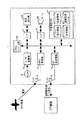
図1は、本実施形態にかかるリストバンドセンサー1の概略構成を示すものである。リストバンドセンサー1は、図示の通り、本発明の設定手段および決定手段としてのシステムコントロール部10、センサー11、GPS(Global Positioning System)受信機13、BT(Bluetooth)送受信機15、本発明の入力手段としての表示操作部18、スピーカ20、不揮発性メモリ21などを含んで構成され、主として、使用者の手首(リスト)に装着されて使用される。
【0033】
システムコントロール部10は、図示しない演算機能を有するCPU、発振回路、各種動作制御のためのプログラムおよびデータを記憶するROM、作業領域としてのRAM等を備え、リストバンドセンサー1全体における動作制御を担うとともに、時計機能を有する。センサー11は、使用者の生体情報、例えば、体温、心拍数、血圧などを検出するための公知の機能を有する。A/D変換部12は、システムコンロール部10からのサンプリングクロックの周期で、検出された生体情報をサンプリングしてデジタルデータに変換する。GPS受信機13は、一般の携帯電話機などに搭載されている機器であり、公知のナビゲーション機能を有し、GPS衛星から送信された電波を、アンテナ14を介して受信し、リストバンドセンサー1の現在位置(緯度と経度)を検出する。
【0034】
BT送受信機15は、例えば、LSI(Large-Scale Integration)を主体として構成され、上述したBluetoothに基づく近距離無線通信機能を有し、他のBT機器(例えば、カーコンピュータ、携帯電話機、パソコン)と、アンテナ16を介してデータ通信を行う機能を有する。より具体的には、BT送受信機15は、マスタ機器として、例えば、半径10m内に存在するスレーブ機器を認識すると、お互いのIDナンバーを交換して確認した後、乱数を発生させて、当該マスタ−スレーブ機器間におけるリンクキー(暗号キー)を生成する(以下、「インクワイヤリー動作」という)。これにより、リストバンドセンサー1とBT機器とが無線通信により接続され、各種データの送受信が行なわれることとなる(以下、「ページング動作」という)。このデータの送受信は、BT送受信機15により、例えば、1MHzごとに分割された79チャネル上(2.402GHz〜2.480GHz)に毎秒1600回の周波数ホッピングを行うように周波数変換され、パケット単位で行なわれる。
【0035】
また、一旦、インクワイヤリー動作が行なわれ、リンクキーが生成されると、次回以降の接続は、設定により、インクワイヤリー動作を経ることなく、リンクキーに基づきページング動作を開始することができる。なお、本実施形態においては、一旦、インクワイヤリー動作が行なわれた後は、次回以降の接続は、インクワイヤリー動作を経ることなく、ページング動作を開始するものとして説明する。
【0036】
システムコントロール部10は、このようなインクワイヤリー動作の際に、使用者からの表示操作部18を介した操作指示に基づいて、その通信相手のBT機器との接続条件を設定する。図2(A)は、一つのBT機器に対して設定される接続条件および、履歴を示すテーブル(以下、単に、「接続条件テーブル」という)のフォーマットを示すものであり、図2(B)は、接続条件が設定された後の接続条件テーブル例を示すものである。このような接続条件テーブルは、図2(B)に示すように、リンクキーが生成された通信相手となるBT機器毎に存在し、後述する不揮発性メモリ21に保存される。
【0037】
図2(A)に示すように、接続条件には、公開条件、公開範囲、確認表示、確認音、制限時間の要素が含まれる。ここで、公開条件とは、通信相手のBT機器との間における利用形態を意味するものであり、恒久利用、一時利用、緊急利用の3形態が用意されている。このうち、恒久利用と一時利用は、何れか一方を通常利用(メイン)とし、他方を副次的利用(サブ)に設定する必要がある。つまり、恒久利用を通常利用するか、或いは、一時利用を通常利用するかを設定するのである。図2(B)の例では、通常利用に設定された方は「○」で、副次的利用に設定された方は「△」で、それぞれ示されている。また、緊急利用は、外部への緊急通報時に利用するものであるが、通信相手のBT機器によっては、これを利用できない場合もある。図2(B)の例では、緊急利用が利用可能なBT機器は、「◎」で、利用不可能なBT機器は「×」でそれぞれ示されている。また、それぞれの利用形態毎に、公開範囲、確認表示、確認音、制限時間を設定することが可能である。これらの利用形態の利用方法については、後述する動作にて詳しく説明する。
【0038】
なお、Bluetoothには、リンクキーを有しなくても、予め用意された固有のキーにより、他のBT機器との間でデータ通信を行う、いわゆる一時利用という機能があるが、本実施形態における一時利用とは異なるものである。
【0039】
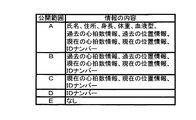
図2(A)、(B)に示す公開範囲とは、通信相手のBT機器に対して送信することができる情報の範囲を意味し、情報の内容に応じて複数のランクに分類される。図3に、公開範囲と情報の内容との対応関係を示す。図3に示すように、公開範囲には、A〜Eまでのランクがあり、それぞれのランクに対して、各情報が割り当てられ、属している。例えば、あるBT機器に対して、公開範囲が「C」に設定された場合には、リストバンドセンサー1は、そのBT機器に対して、「現在の心拍数」、「現在の位置情報」、「IDナンバー」の情報のみ、送信することができる。また、それぞれのランク(A〜E)に対して、どの情報を割り当てるかは、例えば、後述する自宅のパソコン2で設定し、それを、リストバンドセンサー1に転送する。なお、本実施形態において、上記ランクは、A〜Eの5段階としたが、これより多くても少なくてもよい。また、図2(B)において、各ランクに割り当てられた情報の内容は、あくまでも一例であり、これ以外の如何なる情報を割り当ててもよい。
【0040】
図2(A)、(B)に示す確認表示および確認音は、それぞれ、「有」或いは「無」の何れかに設定することができる。例えば、確認表示が「有」に設定された場合には、公開範囲で決められたランクの情報の内容を送信する際に、確認のための警報メッセージが表示操作部18に表示される。また、確認音が「有」に設定された場合には、公開範囲で決められたランクの情報の内容を送信する際に、確認のための警報音がスピーカ20から再生される。これにより、使用者は、ある情報が送信されたことを把握することができ、知らない間に情報が漏洩することを防止することができる。
【0041】
図2(A)、(B)に示す制限時間は、リストバンドセンサー1と通信相手のBT機器との間で、一回の接続で許容できる時間を示すものであり、当該接続時間が経過すると、自動的に接続が解除されることとなる。
【0042】
図2(A)、(B)に示す接続条件テーブル上の履歴には、前回交信日時およびアクセス回数が含まれており、図2(B)に示すように、それぞれの利用形態毎に存在する。
【0043】
システムコントロール部10は、このように設定された接続条件テーブルに基づいて、BT送受信機15によるBT機器に対するデータ送信や、I/F(インターフェース)17を介しての表示操作部18への警報メッセージ表示、さらには、アンプ19を介してのスピーカ20への警報音出力を制御する。
【0044】
次に、表示・操作部18は、各種情報を表示するための表示器や、使用者の操作指示を入力するための各種操作ボタンを備える。図4は、リストバンドセンサー1の外観構成例を示すものであり、表示・操作部18が前面に現れている。図4の例では、表示器18aには、現在時刻、使用者の生体情報が表示されている。この表示器18aには、接続条件設定時には、設定すべき接続条件が表示されることとなる。また、リセットボタン18bは、上記接続条件のクリアなどの指示を入力するためなどに使用される。このリセットボタン18bにより、情報の送信を急遽中止することができるので安全性を向上させることができる。
【0045】
セレクトボタン18cは、上記接続条件設定または更新の際に、所望の設定要素(公開条件、公開範囲等)の選択指示を入力するためなどに使用される。
【0046】
許可ボタン18dは、通信相手のBT機器との接続や接続条件を許可する指示を入力するためなどに使用される。一時利用ボタン18eは、上記公開条件が「恒久利用」に設定されている場合に、「一時利用」に切り換える指示を入力するためなどに使用される。また、図4の符号18fは、緊急ボタンであり、上記公開条件における緊急利用の指示を入力するために使用される。
【0047】
なお、図4に示すこれらの各種操作ボタンの他にも操作ボタンを設け、かかる操作ボタンにて、上述した公開範囲におけるそれぞれのランク(A〜E)に対する情報の割り当て(情報の内容ごとにランク分け)を行うことができるように構成してもよい。また、図4に示すこれらの各種操作ボタンの組み合わせにより、情報の内容ごとにランク分けを行うことができるように構成してもよい。
【0048】
次に、不揮発性メモリ21は、例えば、EEPROM(Electrically Erasable and Programmable Read Only Memory)などからなり、センサー11により検出されA/D変換部12によりデジタルデータに変換された生体情報や、GPS受信機13により検出された位置情報は、さらには、使用者の氏名、住所、身長、体重、血液型などの個人情報、上記接続条件テーブルなどが記憶されている。また、個人情報、生体情報、位置情報は、図3に示すように、公開範囲の各ランクに割り当てられて記憶されている。
【0049】
以上の構成において、リストバンドセンサー1と、通信相手のBT機器とが無線接続し、データ通信が行なわれる場合の動作について、図5乃至10を参照して説明する。図5は、リストバンドセンサー1が、様々なBT機器とデータ通信を行う場合のようすを示すものである。図5の例では、リストバンドセンサー1の通信相手となるBT機器として、自宅内のパソコン(BT送受信機およびアンテナ含む)2、車両内の、例えば、カーナビゲーション装置などのカーコンピュータ(BT送受信機およびアンテナ含む)3、スポーツセンター内のパソコン(BT送受信機およびアンテナ含む)4、携帯電話機(BT送受信機およびアンテナ含む)5がそれぞれ示されている。
【0050】
このうち、自宅内のパソコン2は、公衆回線網を利用して構築されたネットワーク(例えば、インターネット)に接続されており、病院等の緊急センターのサーバ6との間でデータ通信が可能である。また、カーコンピュータ3、携帯電話機5は、移動体通信網を介して、公衆回線網を利用して構築されたネットワークに接続されており、それぞれ、緊急センターのサーバ6との間でデータ通信が可能である。一方、スポーツセンター内のパソコン4は、直接、緊急センターのサーバ6には接続されていない。
【0051】
リストバンドセンサー1は、このような各BT機器のそれぞれと無線通信を行うこととなる。図6は、無線通信時におけるリストバンドセンサー1のシステムコントロール部10の接続処理を示すフローチャートである。
【0052】
先ず、リストバンドセンサー1が、カーコンピュータ3と無線通信を行う場合を例にとって説明する。リストバンドセンサー1が、カーコンピュータ3との通信(接続)可能範囲内(例えば、半径10m内)に入ると、BT送受信機15は、カーコンピュータ3を認識し、カーコンピュータ3のIDナンバーを取得して、これを、システムコントロール部10に伝える。
【0053】
これにより、システムコントロール部10は、通信可能範囲内にBT機器であるカーコンピュータ3が存在することを確認すると(ステップS1)、IDナンバーから、カーコンピュータ3が新規接続のBT機器であるか否か、即ち、リンクキーが既に作成されているか否かを判断する(ステップS2)。リンクキーが既に作成されている場合、システムコントロール部10は、そのリンクキーに基づくページング動作開始指令をBT送受信機15に与えるとともに、接続条件テーブルを参照し、該当する接続条件を表示・操作部18の表示器18aに表示させる(ステップS3)。こうして、リストバンドセンサー1とカーコンピュータ3の接続が確立する。
【0054】
一方、リンクキーが未だ作成されていない場合、システムコントロール部10は、BT送受信機15に対し、インクワイヤリー動作指令を与える(ステップS4)。これにより、BT送受信機15にて、カーコンピュータ3とのリンクキーが生成され、システムコントロール部10に伝えられる。そして、システムコントロール部10は、カーコンピュータ3との接続条件設定処理を開始する(ステップS5)。図7(B)は、図6のステップS5における接続条件設定処理を示すフローチャートであり、図7(A)は、その時のBT機器(ここでは、カーコンピュータ3)の接続条件設定処理を示すフローチャートである。なお、図7(A)および(B)において、破線矢印線は、リストバンドセンサー1とBT機器間のデータの流れを示す。
【0055】
図7(A)において、カーコンピュータ3側でもリストバンドセンサー1を認識し、新規接続のBT機器か否かを判断する(ステップ51)。新規接続であると判断した場合には、カーコンピュータ3は、リストバンドセンサー1に接続条件の要求(無線送信)を行う(ステップS52)。この接続条件は、予め、カーコンピュータ3側で設定されている。例えば、公開条件においては、恒久利用をメインに設定し、緊急利用は利用可能(図5に示すように、カーコンピュータ3は、移動体通信網および公衆回線網を介して緊急センターのサーバ6に接続可能なため)とする設定がされる。
【0056】
次に、リストバンドセンサー1のBT送受信機15がかかる接続条件を受信すると、図7(B)に示すように、システムコントロール部10は、これを認識し(ステップS11)、表示操作部18に、かかる接続条件を表示させる(ステップS12)。なお、接続条件のうち、確認表示、確認音、制限時間については、リストバンドセンサー1側に代表例が不揮発性メモリ21に予め記憶されており、それらの情報が読み出されて表示操作部18に表示されることとなる。
【0057】
こうして、表示操作部18の表示器18a上に表示された接続条件例を図8(A)に示す。BT機器からの接続条件を変更せずそのまま採用する場合、使用者が、この表示状態で、表示操作部18の許可ボタン18dを押下すると、システムコントロール部10は、接続条件が承諾されたことを認識し(ステップS13)、当該接続条件を承諾する旨の情報の送信指令をBT送受信機15に与える(ステップS14)。これにより、その承諾する旨の情報が、リストバンドセンサー1からカーコンピュータ3に送信されることとなる。
【0058】
一方、BT機器からの接続条件を変更する場合、使用者による、表示操作部18のセレクトボタン18c、一時ボタン18e、許可ボタン18dの操作に基づき、システムコントロール部10は、接続条件である公開条件、公開範囲、確認表示、確認音、制限時間の設定変更を行う(ステップS15〜S19)。以下に、具体的な設定変更例を説明する。
【0059】
図8(A)の例では、公開条件として、恒久利用が「○」(即ち、メインとして)で、一時利用が「△」(即ち、サブとして)でそれぞれ表示されており、緊急利用が「◎」(即ち、利用可能である)で表示されている。このうち、恒久利用の右横の設定要素「○」がカーソル180で選択されており、表示欄182には、この選択された恒久利用に対応する公開条件、確認表示、確認音、制限時間が表示されている。このカーソル180は、各設定要素の上を、表示操作部18のセレクトボタン18cの押下により順次移動する。
【0060】
また、図8(A)の例において、一時利用の右横の設定要素「△」をカーソル180で選択した場合、表示欄182には、一時利用に対応する公開条件、確認表示、確認音、制限時間が表示されることとなる。さらに、緊急利用の右横の設定要素「◎」をカーソル180で選択した場合、表示欄182には、緊急利用に対応する公開条件、確認表示、確認音、制限時間が表示されることとなる。
【0061】
ここで、図8(A)の例において、恒久利用をサブとするように設定変更したい場合には、恒久利用の右横の設定要素「○」がカーソル180で選択されている状態で、例えば、一時ボタン18eを押下すると、「○」の表示が「△」に変更され、サブに設定変更することができる(この場合、一時利用の「△」は、自動的に「○」に変更される)。また、緊急利用を使用しない場合には、緊急利用の右横の設定要素「◎」がカーソル180で選択されている状態で、一時ボタン18eを押下すると、「◎」の表示が「×」に変更され、緊急利用を利用しない設定に変更することができる。
【0062】
また、所望の利用形態、例えば、恒久利用の右横の設定要素「○」をカーソル180で選択している状態で、許可ボタン18dを押下すると、図8(B)に示すように、カーソル180が表示欄182内の公開範囲の右横の設定要素「A」に移動することとなる。この状態で、一時ボタン18eを押下する毎に、かかる設定要素は、「A」、「B」、「C」・・と変更されることとなる。例えば、図8(B)および(C)に示すように、一時ボタン18eを押下により、公開範囲の設定要素が「A」から「C」に変更される。また、確認表示、確認音、制限時間の設定要素を変更する場合にも、同様に、セレクトボタン18cにて、順次、設定要素上を移動させ、一時ボタン18eにて変更することとなる。
【0063】
そして、このように変更した内容を接続条件として採用する場合、図8(D)に示すように、使用者が、セレクトボタン18cにより、許可181を選択し、許可ボタン18dを押下すると、システムコントロール部10は、これに応答し(ステップS20)、設定された接続条件の送信指令をBT送受信機15に与える(ステップS21)。これにより、その設定された接続条件が、リストバンドセンサー1からカーコンピュータ3に送信されることとなる。
【0064】
次に、ステップS22において、システムコントロール部10は、上記接続条件をリンクキーに対応付けて不揮発性メモリ21における接続条件テーブル(図2(B)参照)に記憶し、図6に示す処理に戻り、接続処理を終了する。
【0065】
一方、上記ステップS14またはS21において、接続条件若しくは情報がカーコンピュータ3に送信されると、図7(A)に示すように、カーコンピュータ3はこれを応答として認識し(ステップS53)、上記ステップS52で要求した接続条件が承諾されたか否かを判断する(ステップS54)。要求した接続条件が承諾された場合には、その接続条件を認識(メモリに記憶)する(ステップS55)。一方、要求した接続条件が承諾されない場合には、リストバンドセンサー1より受信した接続条件を認識(メモリに記憶)する(ステップS55)。
【0066】
なお、以上のように設定された接続条件は、図示しないが、表示操作部18の各種ボタンにより、使用者が任意に変更可能である。
【0067】
以上のように、リストバンドセンサー1おける接続処理が終了し、リストバンドセンサー1とBT機器(ここでは、カーコンピュータ3)の接続が確立すると、データ通信処理が開始される。
【0068】
図9(A)は、リストバンドセンサー1のシステムコントロール部10のデータ通信処理を示すフローチャートであり、図9(B)は、その時のBT機器(ここでは、カーコンピュータ3)のデータ通信処理を示すフローチャートである。
【0069】
図9(A)に示すデータ通信処理において、システムコントロール部10は、緊急利用の指示があるか否かを監視しており(ステップS31)、使用者が、表示操作部18の緊急ボタン18fを押下すると、システムコントロール部10は、これに応答し、緊急利用処理(ステップS32)を開始する。緊急利用処理の詳細については後述する。
【0070】
緊急利用の指示がない場合、システムコントロール部10は、不揮発性メモリ21に記憶された接続条件テーブルの公開条件を参照し、メインとなっている利用形態が一時利用であるか否かを判断する(ステップS33)。一時利用である場合には、システムコントロール部10は、これを認識し(ステップS34)、ステップS38に移行する。一方、一時利用でない場合には、システムコントロール部10は、ステップS35に移行する。例えば、図2(B)に示すカーコンピュータ3の公開条件では、恒久利用がメインとなっているため、この場合は、ステップS35に移行することとなる。
【0071】
ステップS35では、システムコントロール部10は、一時利用への変更指示があるか否か、即ち、表示操作部18の一時利用ボタン18eが押下されたか否かを判断する。使用者が、表示操作部18の一時利用ボタン18eを押下すると、システムコントロール部10は、これに応答し、当該接続中に限り、利用形態を一時利用に変更して認識する。これにより、例えば、通常、使用者が単独で車両に乗り、リストバンドセンサー1における情報をカーコンピュータ3に送信して表示部に表示させている場合に、たまたま、他人を乗せた場合にも、情報の公開範囲を制限することができる。
【0072】
一方、一時利用への変更指示がない場合、システムコントロール部10は、恒久利用の許可指示があるか否かを判断する(ステップS36)。使用者が、表示操作部18の許可ボタン18dを押下すると、システムコントロール部10は、恒久利用を認識し(ステップS37)、ステップS38に移行する。ここで、恒久利用の場合に、一時利用とは異なり、恒久利用の許可指示(ステップS36)を経て、ステップS38に移行するようにしたのは、通常、恒久利用の場合、一時利用よりも情報の公開範囲を広く設定するので、不用意に情報が漏洩するのを防止するためである。但し、ステップS36の処理をパスするように構成してもよい。
【0073】
ステップS38では、システムコントロール部10は、カーコンピュータ3からの所定の情報の送信要求があるか否かを監視している。カーコンピュータ3は、このような所定の情報の送信要求を、図9(B)に示すデータ通信処理に基づいて行う。図9(B)に示すカーコンピュータ3のデータ通信処理では、先ず、カーコンピュータ3は、リストバンドセンサー1から緊急利用の情報を受信したか否かを監視している(ステップS61)。緊急利用の情報を受信していない場合には、所定の情報の送信要求を行うか否かを判断し(ステップS63)、送信要求を行う場合には、リストバンドセンサー1に対し、所定の情報の送信要求を行う(ステップS64)。このような所定の情報の送信要求を行うか否か、および何の情報の送信要求を行うか否かについては、予め、カーコンピュータ3において設定されている。
【0074】
図9(A)の説明に戻り、カーコンピュータ3から、所定の情報の送信要求があった場合には、システムコントロール部10は、不揮発性メモリ21に記憶された接続条件テーブルの公開範囲を参照し、要求された情報が当該公開範囲内である否かを判断する(ステップS39)。例えば、リストバンドセンサー1側で恒久利用が認識されていた(上記ステップS37にて)場合に、カーコンピュータ3から、図3に示す公開範囲「A」若しくは「B」に対応する情報が要求されたとすると、図2(B)に示す接続条件テーブル上の公開範囲は「C」に設定されているので、システムコントロール部10は、公開範囲外と判断して、要求された情報の送信は行わない。
【0075】
一方、例えば、リストバンドセンサー1側で恒久利用が認識されていた(上記ステップS37にて)場合に、カーコンピュータ3から、図3に示す公開範囲「C」に含まれる情報が要求されたとすると、図2(B)に示す接続条件テーブル上の公開範囲は「C」に設定されているので、システムコントロール部10は、公開範囲内と判断して、ステップS40に移行する。
【0076】
ステップS40では、システムコントロール部10は、接続条件テーブルにおける当該利用形態に対応する確認表示および確認音に基づいて、表示および音声出力処理を行う。例えば、図2(B)の例では、カーコンピュータ3の恒久利用に対応する確認表示および確認音は、ともに「無」に設定されているので、警報メッセージ表示および警報音出力が行なわれず、ステップS41に移行する。
【0077】
ステップS41では、システムコントロール部10は、カーコンピュータ3から要求された情報の送信指令をBT送受信機15に与える。こうして、カーコンピュータ3に対し、その情報が送信されることとなる。
【0078】
そして、図9(B)に示すように、カーコンピュータ3では、かかる情報を受信し(ステップS65)、それを、カーコンピュータ3の表示部に表示する(ステップS66)。例えば、カーコンピュータ3の表示部上に、図3に示す公開範囲「C」の情報である「現在の心拍情報」、「現在の位置情報」、「IDナンバー」が表示されることとなる。これにより、使用者は、カーコンピュータ3の表示部上で、自己の体調等を確認することができる。
【0079】
また、カーコンピュータ3は、使用者(ドライバー)の現在の心拍情報から、緊張状態や疲労・眠気を推定し、さらに車速情報とを組み合わせデータ解析した後に、使用者(ドライバー)に音声や文字等で案内する。例えば、脈拍数(または心拍数)の上昇と、低速の断続運転(渋滞等)継続(車速情報により検出)とにより、いらいら状態を推定する。また、脈拍数(または心拍数)の低下と、速度超過(車速情報により検出)とにより、興奮・緊張状態を推定する。さらには、脈拍数(または心拍数)の低下と、車両の蛇行運転(車速情報により検出)とにより、眠気状態を推定する。そして、カーコンピュータ3は、これらの推定結果に基づき、周辺の休憩施設をナビゲーションで検索して、使用者(ドライバー)に音声や文字等で案内する。
【0080】
さらに、カーコンピュータ3は、ラジオ音楽聴取時の心拍数の増加を検出することにより、好みの曲と推定して、演奏楽曲の保存やタイトル検索を行って、使用者(ドライバー)に提示する他、音声によるクイズや、いくつかの質問後の使用者(ドライバー)の生体反応をみて、音声で反応を伝える等の処理を行う。
【0081】
ところで、上記ステップS39において、リストバンドセンサー1側で一時利用が認識されていた(上記ステップS34にて)場合に、カーコンピュータ3から要求される情報が図3に示す公開範囲「C」であったとしても、図2(B)に示す接続条件テーブル上の公開範囲は「D」に設定されているので、システムコントロール部10は、公開範囲外と判断して、要求された情報の送信は行わない。
【0082】
一方、カーコンピュータ3から、リストバンドセンサー1側で一時利用が認識されていた(上記ステップS34にて)場合に、図3に示す公開範囲「D」に含まれる情報が要求されたとすると、図2(B)に示す接続条件テーブル上の公開範囲は「D」に設定されているので、システムコントロール部10は、公開範囲内と判断して、ステップS40に移行する。この場合、図2(B)の例では、カーコンピュータ3の一時利用に対応する確認表示および確認音はともに「有」に設定されているので、システムコントロール部10により、表示操作部18の表示器18a上に警報メッセージが表示され、スピーカ20から警報音が出力されることとなる。また、この場合には、カーコンピュータ3における表示部上には、「IDナンバー」のみが表示されることとなる。これにより、使用者の車両に他人が乗ってきた場合にも、その他人に、使用者の現在の心拍情報などを知られることを防ぐことができる。また、警報音、警報メッセージ表示等で、通常利用でないことを知らせることができる。
【0083】
図9(A)に示すステップS42では、システムコントロール部10は、カーコンピュータ3との接続時間が、接続条件テーブルにおける現在の利用形態に対応する制限時間を経過したか否かを判断し(ステップS42)、経過したと判断した場合には、データ通信処理を終了する。一方、制限時間が「無」に設定されていた場合や、制限時間が経過していない場合には、ステップS31に戻り、上記の処理を繰り返す。なお、データ通信処理の終了若しくは、その他の任意のタイミングで、図2(B)に示すように、不揮発性メモリ21における履歴(BT機器との交信日時およびアクセス回数など)が更新される。
【0084】
次に、上述したように、図9(A)に示すステップS31において、使用者が、表示操作部18の緊急ボタン18fを押下すると、システムコントロール部10は、これに応答し、緊急利用処理(ステップS32)を開始する。
【0085】
図10(A)は、図9(A)のステップS32における緊急利用処理を示すフローチャートであり、図10(B)は、図9(B)のステップS62における緊急利用処理を示すフローチャートである。
【0086】
図10(A)において、先ず、システムコントロール部10は、接続条件テーブルを参照して、緊急センターに接続可能なBT機器を検索する(ステップS43)。ここで検索対象となるBT機器は、リストバンドセンサー1と通信可能範囲内にあり、かつ、接続条件テーブルにて緊急利用が利用可能に設定されているBT機器である。検索した結果、緊急センターに接続可能なBT機器がある場合、システムコントロール部10は、そのBT機器を選定し、接続条件テーブルにおける警報利用に対応する確認表示および確認音に基づいて、表示および音声出力処理を行う(ステップS44)。
【0087】
そして、システムコントロール部10は、接続条件テーブルにおける緊急利用に対応する公開範囲内の情報の送信指令を、BT送受信機15に与える。これにより、かかる情報が選定されたBT機器に送信されることとなる。例えば、選定されたBT機器が、カーコンピュータ3であった場合には、図2(B)に示す接続条件テーブルで設定された公開範囲「A」に対応する情報が、カーコンピュータ3に送信されることとなる。
【0088】
こうして、カーコンピュータ3が警報利用に対応する公開範囲の情報を受信すると、図9(B)を用いて説明したように、ステップS61で、カーコンピュータ3は、これを認識し、図10(B)に示す緊急利用処理(ステップS62)を開始する。
【0089】
図10(B)の処理では、先ず、カーコンピュータ3は、緊急センターのサーバ6に移動体通信網および公衆回線網を介して接続する。そして、カーコンピュータ3は、リストバンドセンサー1から受信した情報を、緊急センターのサーバ6に送信する(ステップS68)。次に、カーコンピュータ3は、緊急センターのサーバ6から、その使用者に関する追加の情報の要求があるか否か、例えば、所定時間監視しており(ステップS69)、追加の情報の要求がある場合には、かかる情報の要求を、リストバンドセンサー1に対して行う(ステップS70)。
【0090】
図10(A)の説明に戻り、ステップS46で、リストバンドセンサー1のシステムコントロール部10は、カーコンピュータ3から追加の情報の要求があるか否か、例えば、所定時間監視しており、追加の情報の要求がある場合には、システムコントロール部10は、接続条件テーブルの警報利用に対応する公開範囲を参照し、追加要求された情報が当該公開範囲内である否かを判断する(ステップS47)。追加要求された情報が当該公開範囲内であると判断した場合には、システムコントロール部10は、接続条件テーブルにおける警報利用に対応する確認表示および確認音に基づいて、表示および音声出力処理を行い(ステップS48)、追加要求された情報の送信指令をBT送受信機15に与える(ステップS49)。これにより、カーコンピュータ3に対し、その追加の情報が送信されることとなる。
【0091】
こうして、図10(B)のステップS71に示すように、カーコンピュータ3が追加の情報を受信すると、カーコンピュータ3は、リストバンドセンサー1から受信した追加の情報を、上記と同様、ステップS69、70の処理を行い、緊急センターのサーバ6に送信する。
【0092】
このように、リストバンドセンサー1の表示操作部18の緊急ボタン18fが押下された場合には、恒久利用および一時利用とは別に、迅速に公開範囲内の情報が緊急センターに送信される。従って、例えば、使用者の具合が急に悪くなった場合に、即座に病院等の緊急センターに通報することができる。
【0093】
なお、ステップS45にて送信する情報を最小限の情報となるように設定しておき(例えば、IDナンバーのみ)、その後、ステップS46にて追加の情報の送信要求があった場合に、接続条件テーブルで設定された公開範囲内の情報をステップS47〜ステップS49の処理で送信するようにしてもよい。
【0094】
一方、図10(A)に示すステップS46、および図10(B)に示すステップS69において、所定時間内に追加情報の要求がないと判断された場合には、それぞれ、図9(A)、(B)の処理に戻る。
【0095】
次に、リストバンドセンサー1が、スポーツセンターのパソコン4と無線通信を行う場合を例にとって説明する。
【0096】
この場合にも、リストバンドセンサー1のシステムコントロール部10は、上記カーコンピュータ3で説明したのと同様、図6に示す接続処理、および新規接続の場合には図7に示す接続条件設定処理を行い、スポーツセンターのパソコン4との接続を確立する。かかる接続条件設定処理により、例えば、図2(B)に示すように、公開条件は、恒久利用がメインに、緊急利用は利用不可に、それぞれ設定され、公開範囲は、一時利用が「C」に設定される。緊急利用が利用不可であるのは、図5に示すように、スポーツセンターのパソコン4が緊急センターのサーバ6に接続できないためであり、図7(B)に示すステップS12の表示操作部18の表示器18aにおける緊急利用が、当初から「×」に表示され、「◎」への変更設定が不可能となる。
【0097】
次に、図9(A)に示すデータ通信処理が開始され、例えば、使用者が、表示操作部18の緊急ボタン18fを押下すると、システムコントロール部10は、これに応答し(ステップS31)、上述したように、図10(A)に示す緊急利用処理(ステップS32)を開始する。図10(A)では、システムコントロール部10は、ステップS43で、上述したように、緊急センターに接続可能なBT機器を検索することとなるが、この場合、スポーツセンターのパソコン4は、緊急利用が利用できないので選定されることはない。しかしながら、他のBT機器、例えば、図5に示す携帯電話機5が、同時に接続状態にあれば、その携帯電話機5が選定され、上述したカーコンピュータ3の場合と同様、ステップS44以降の処理が行なわれることとなる。
【0098】
次に、図9(A)の説明に戻り、ステップS33では、システムコントロール部10は、接続条件テーブルの公開条件を参照し、メインとなっている利用形態が一時利用であるか否かを判断する。スポーツセンターのパソコン4の場合、図2(B)に示すように、公開条件は、メインが一時利用に設定されているので、ステップS34に以降し、システムコントロール部10は、一時利用を認識する。なお、ステップS35では、メインが恒久利用であるときに、一時利用への変更を可能としているが、これと同様に、メインが一時利用であるときに、恒久利用への変更を可能とするように構成してもよい。
【0099】
次に、スポーツセンターのパソコン4から所定の情報の要求があった場合、システムコントロール部10は、接続条件テーブルの公開範囲を参照し、要求された情報が当該公開範囲内である否かを判断する(ステップS39)。この場合、スポーツセンターのパソコン4から、図3に示す公開範囲「A」若しくは「B」に対応する情報が要求されたとすると、スポーツセンターのパソコン4は、図2(B)に示すように、公開範囲が「C」に設定されているので、システムコントロール部10は、公開範囲外と判断して、要求された情報の送信は行わない。一方、スポーツセンターのパソコン4から、図3に示す公開範囲「C」に含まれる情報が要求されたとすると、システムコントロール部10は、公開範囲内と判断して、ステップS40に移行する。この場合、図2(B)に示すように、確認表示および確認音はともに「有」に設定されているので、システムコントロール部10により、表示操作部18の表示器18a上に警報メッセージを表示し、スピーカ20から警報音を出力した後、スポーツセンターのパソコン4から要求された情報を送信することととなる。
【0100】
ここで、スポーツセンター内には、図示しないが、運動負荷試験を行うための様々なトレッドミル(ウォーキングマシン等)が設置されており、これらは、LAN等のネットワークを介してパソコン4に接続されている。使用者が、あるトレッドミルを利用する場合、所定の操作により、上記データ通信処理にてパソコン4に送信された現在の心拍数情報が、そのトレッドミルに転送され、そこで、最適な負荷を計算し、運動強度を調整することができる。
【0101】
なお、トレッドミル自体にBluetooth通信機能を持たせBT機器とし、リストバンドセンサー1との無線通信を行うように構成してもよい。この場合にも、図6、図7、図9、図10の処理が、上記と同様に行なわれ、トレッドミルごとに接続条件、即ち、公開条件、公開範囲等を異ならしめることができる。
【0102】
次に、リストバンドセンサー1が、自宅のパソコン2と無線通信を行う場合を例にとって説明する。
【0103】
この場合にも、リストバンドセンサー1のシステムコントロール部10は、上記カーコンピュータ3で説明したのと同様、図6に示す接続処理、および新規接続の場合には図7に示す接続条件設定処理を行い、自宅のパソコン2との接続を確立する。なお、この場合も、図6、図7、図9、図10の処理を行うことができるが、これらの処理の重複した説明は省略する。
【0104】
リストバンドセンサー1の不揮発性メモリ21に記憶される個人情報は、自宅のパソコン2で作成され、図示しないが、図9(A)に示すデータ通信処理中に無線データ通信にて、リストバンドセンサー1に転送することができる。
【0105】
また、上述したように、自宅のパソコン2で、上述した公開範囲におけるそれぞれのランク(A〜E)に対する情報の割り当て(情報の内容ごとにランク分け)を行い、図9(A)に示すデータ通信処理中に無線データ通信にて、リストバンドセンサー1に転送することができる。
【0106】
さらに、自宅のパソコン2にヘルスチェックを行う機能を備えて、使用者が帰宅した際に、データ通信処理にて、自宅のパソコン2に公開範囲に応じた生体情報を、送信し自動的にヘルスチェックし、そのヘルスチェックの結果を、パソコン2の画面上に表示させるようにしてもよい。この場合、自宅に顧客が来た際には、上述したように、表示操作部18の一時ボタン18eにより、一時利用に変更することができるので、その顧客にヘルスチェックの結果を見られることを防ぐことができる。
【0107】
以上説明したように、上記実施形態によれば、BT機器ごとに公開条件、公開範囲等の接続条件を設定し、当該接続条件に基づいて、接続するBT機器に応じた、また、目的に応じた情報を区別して送信することができるので、不必要な情報の送信を防止することができ、効果的に、プライバシー情報の漏洩を防止することができる。また、複数ある利用形態ごとに異なる公開範囲を設定ように構成したので、使用者は、同一の相手機器でも、その接続目的に応じて、情報を公開する範囲を決定することができる。また、公開範囲を情報の内容に応じて複数のランクに分類し、しかも、これらのランクへの情報の割り当てを、使用者が任意に行うことができるので、より効果的に不必要な情報の送信を防止することができ、情報通信機器の利便性を向上させることができる。
【0108】
なお、上記実施形態においては、本発明にかかる情報通信機器としてリストバンドセンサーを例にとって説明したが、これに限定されるものではなく、その他の様々な機器に適用することが可能である。
【0109】
また、上記実施形態においては、リストバンドセンサーにGPS受信機13を備えさせ、位置情報を検出できるように構成したが、GPS受信機を備えた携帯電話機にて検出された位置情報をリストバンドセンサーに転送するように構成してもよい。
【0110】
また、上記実施形態においては、近距離無線通信方式は、Bluetooth方式を適用したが、これに限定されず、この他にも、例えば、802.11b、IEEE802.11e等による広帯域なスループットを実現できる無線規格や、さらには、PulsONテクノロジと呼ばれる拡散型無線通信(数年以内に1Gbpsの通信速度を実現)等による無線規格を適用するようにしてもよい。
【0111】
【発明の効果】
以上説明したように、本発明によれば、相手機器ごとに利用形態、公開範囲等を設定し、これらに基づいて、接続する相手機器に応じた、また、目的に応じた情報を区別して送信することができるので、不必要な情報の送信を防止することができ、効果的に、プライバシー情報の漏洩を防止することができる。また、複数ある利用形態ごとに異なる公開範囲を設定ように構成したので、使用者は、同一の相手機器でも、その接続目的に応じて、情報を公開する範囲を決定することができる。また、公開範囲を情報の内容に応じて複数のランクに分類し、しかも、これらのランクへの情報の割り当てを、使用者が任意に行うことができるので、より効果的に不必要な情報の送信を防止することができ、情報通信機器の利便性を向上させることができる。
【図面の簡単な説明】
【図1】本実施形態にかかるリストバンドセンサー1の概略構成を示す図である。
【図2】(A)は、一つのBT機器に対して設定される接続条件および、履歴を示すテーブルのフォーマットを示す図である。(B)は、接続条件が設定された後の接続条件テーブル例を示す図である。
【図3】公開範囲と情報の内容との対応関係を示す図である。
【図4】リストバンドセンサー1の外観構成例を示す図である。
【図5】リストバンドセンサー1が、様々なBT機器とデータ通信を行う場合のようすを示す図である。
【図6】無線通信時におけるリストバンドセンサー1のシステムコントロール部10の接続処理を示すフローチャートである。
【図7】(A)は、BT機器の接続条件設定処理を示すフローチャートである。(B)は、図6のステップS5における接続条件設定処理を示すフローチャートである。
【図8】表示操作部18の表示器18a上に表示された接続条件例を示す図である。
【図9】(A)は、リストバンドセンサー1のシステムコントロール部10のデータ通信処理を示すフローチャートである。(B)は、その時のBT機器のデータ通信処理を示すフローチャートである。
【図10】(A)は、図9(A)のステップS32における緊急利用処理を示すフローチャートである。(B)は、図9(B)のステップS62における緊急利用処理を示すフローチャートである。
【符号の説明】
1 リストバンドセンサー
2 自宅内のパソコン
3 カーコンピュータ
4 スポーツセンター内のパソコン
5 携帯電話機
10 システムコントロール部
11 センサー
12 A/D変換部
13 GPS受信機
14、16 アンテナ
15 BT送受信機
17 I/F
18 表示操作部
19 アンプ
20 スピーカ
21 不揮発性メモリ[0001]
BACKGROUND OF THE INVENTION
The present invention relates to an information communication device capable of data communication using a wireless communication method, and more particularly to a field of communication technology capable of protecting information related to privacy in an information communication terminal.
[0002]
[Prior art]
In recent years, using a short-range wireless communication method called Bluetooth, for example, home appliances (for example, televisions, refrigerators, etc.), printers, mobile phones, personal digital assistants (PDAs), personal computers, network applications Research and development for sharing intelligent information among multiple electronic devices such as servers and realizing intelligent mechanisms are actively conducted. Here, Bluetooth is the name of a short-range wireless communication technology standard that started standardization activities in Japan and Europe in May 1998. This Bluetooth constructs a short-range wireless communication network with a maximum data transmission speed of about 1 Mbps and a maximum transmission distance of about 10 m, and performs data communication. A 2.4 GHz band ISM (Industrial) that can be used without permission. Scientific Medical) Radio frequency is transmitted and received between electronic devices by adopting frequency hopping spread spectrum technology that sets 79 channels with 1MHz bandwidth in frequency band and switches channels 1600 times per second.
[0003]
In addition, an electronic device adopting Bluetooth (hereinafter referred to as “BT device”) adopts a slave master method, and determines a frequency hopping pattern according to processing contents and a communication partner controlled by the master device. Divide into slave devices. The master device can perform data communication simultaneously with seven slave devices at a time. For example, when a master device recognizes a slave device existing within a radius of 10 m, it exchanges and confirms the ID numbers of each other, generates a random number, and generates a link key (encryption key) between the master and slave devices. Generate authentication process. By such authentication processing, a connection between the master and slave devices is established, and information contained in each other is automatically transmitted and received. In addition, once authentication processing is performed between a master device and a slave device, connection is automatically established between the master and slave devices based on the link key without performing authentication processing during subsequent connections. Data communication is possible. The content of information transmitted / received between the master and slave devices is determined in advance in each BT device.
[0004]
[Problems to be solved by the invention]
In this way, by adopting a short-range wireless communication method such as Bluetooth, it is possible to automatically exchange information between various electronic devices, but on the other hand, there is a possibility of leakage of privacy information There is a problem that there is.
[0005]
The present invention has been made in view of the above problems, and provides an information communication device and an information communication method capable of transmitting information according to the purpose and preventing unnecessary information from being transmitted. With the goal.
[0006]
[Means for Solving the Problems]
In order to solve the above-mentioned problem, the invention according to
[0007]
According to the first aspect of the present invention, the disclosure range of the information to be transmitted to a plurality of counterpart devices to be connected is set for each counterpart device, so the information disclosed for each counterpart device is limited. It is possible to distinguish and transmit information according to the connected device. Accordingly, unnecessary information transmission can be prevented, and leakage of privacy information can be effectively prevented.In addition, since a different disclosure range is set for each of a plurality of usage forms, the user can determine the range of information disclosure even for the same counterpart device according to the connection purpose.
[0008]
The invention according to
[0009]
According to the second aspect of the present invention, since the user sets the disclosure range for each counterpart device via the input means, the user can respond to the purpose of the connected counterpart device. , Can determine the scope of information disclosure. Therefore, the convenience of the information communication device can be improved.
[0014]
Claim3The invention described in claim1 or 2In the information communication device according to
[0015]
Claim4The invention described in claim3In the information communication device described in the
[0016]
Claim4According to the invention described in the above, it is possible to appropriately change the usage form normally used according to the connection purpose of the user at that time.
[0021]
Claim5The invention described in claimAny one of 1 to 4In the information and communication equipment described in,in frontThe use form includes a use form for emergency use, and based on an emergency use instruction from a user via the input means, means for transmitting information on a public range corresponding to the emergency use to the counterpart deviceMoreConfigure to include.
[0022]
Claim5According to the invention described in (1), if the contents of information to be transmitted in an emergency are set in advance, the information can be transmitted promptly regardless of other usage forms.
[0023]
Claim6The invention described in claimAny one of 1 to 5In the information communication equipment described inThe setting means includesWhether to let the user perceive transmission of information within the disclosure range in association with each counterpart device or each usage modeWhen performing the perceptual setting and transmitting the information to be transmitted to the connected counterpart device, based on the perceptual setting performed by the setting unit,Means for causing a user to perceive transmission of information within the disclosure range;MoreConfigure to include.
[0024]
Claim6According to the invention described in (1), when transmitting information within the open range, the user is made to perceive, for example, an alarm sound is output from a speaker or an alarm message is displayed on a display. However, it is possible to prevent information from leaking without knowing it.
[0025]
Claim7The invention described in
[0026]
Claim7According to the invention described in (1), it is possible to set transmission permission / inhibition for each information by assigning information to these ranks. Therefore, unnecessary information transmission can be prevented more effectively.
[0027]
Claim8The invention described in claim7In the information communication device described in (1), the content of information that should belong to a predetermined rank of the disclosure range is set based on an instruction from a user via the input unit.
[0028]
Claim8According to the invention described in (4), the content of information that should belong to a predetermined rank in the disclosure range can be arbitrarily set by the user, so that the convenience of the information communication device can be improved.
[0029]
Claim9In the information communication method capable of automatically recognizing and connecting to a counterpart device existing within a communicable range and performing data communication with the counterpart device, the invention described in the above should be transmitted to the counterpart device The disclosure range of information is set for each counterpart device, and when there is a request for transmission of predetermined information from the connected counterpart device, the setting is performed.didDecide whether to send the requested information based on the disclosure rangeHowever, when setting the disclosure range, a different disclosure range is set for each of a plurality of usage forms.To be configured.
[0030]
Claim9According to the invention described inThe disclosure range of the information to be sentFor each partner deviceSet inCan be determinedAs well as different disclosure ranges for each usage pattern,Information corresponding to the connected device to be connected can be distinguished and transmitted. Accordingly, unnecessary information transmission can be prevented, and leakage of privacy information can be effectively prevented.Further, it is possible to determine the range of information to be disclosed for the same counterpart device according to the connection purpose.
[0031]
DETAILED DESCRIPTION OF THE INVENTION
DESCRIPTION OF EXEMPLARY EMBODIMENTS Hereinafter, preferred embodiments of the invention will be described with reference to the accompanying drawings. The following description is an embodiment when the information communication device according to the present invention is applied to the wristband sensor.
[0032]
FIG. 1 shows a schematic configuration of a
[0033]
The
[0034]
The
[0035]
Also, once the ink-wired operation is performed and the link key is generated, the paging operation can be started based on the link key without going through the ink-wired operation for the subsequent connections according to the setting. . In the present embodiment, it is assumed that after the ink-wired operation is once performed, the connection after the next time starts the paging operation without going through the ink-wired operation.
[0036]
In such an inquiry operation, the
[0037]
As shown in FIG. 2A, the connection condition includes elements of a disclosure condition, a disclosure range, a confirmation display, a confirmation sound, and a time limit. Here, the disclosure condition means a use form with the BT device of the communication partner, and three forms of permanent use, temporary use, and emergency use are prepared. Of these, permanent use and temporary use must be set to normal use (main) and the other to secondary use (sub). That is, it is set whether permanent use is normally used or temporary use is normally used. In the example of FIG. 2B, the one set for normal use is indicated by “◯”, and the one set for secondary use is indicated by “Δ”. Moreover, although emergency use is used at the time of emergency notification to the outside, depending on the BT device of the communication partner, this may not be used. In the example of FIG. 2B, BT devices that can be used for emergency use are indicated by “◎”, and BT devices that cannot be used are indicated by “x”. Moreover, it is possible to set a disclosure range, a confirmation display, a confirmation sound, and a time limit for each usage mode. The usage method of these usage forms will be described in detail in the operation described later.
[0038]
Note that Bluetooth has a function of so-called temporary use in which data communication is performed with another BT device using a unique key prepared in advance, even without a link key. It is different from temporary use.
[0039]
The disclosure range shown in FIGS. 2A and 2B means the range of information that can be transmitted to the BT device of the communication partner, and is classified into a plurality of ranks according to the content of the information. FIG. 3 shows the correspondence between the disclosure range and the information content. As shown in FIG. 3, the disclosure range includes ranks A to E, and each piece of information is assigned and belongs to each rank. For example, when the disclosure range is set to “C” for a certain BT device, the
[0040]
The confirmation display and confirmation sound shown in FIGS. 2A and 2B can be set to either “present” or “not present”, respectively. For example, when the confirmation display is set to “present”, a warning message for confirmation is displayed on the
[0041]
The time limits shown in FIGS. 2 (A) and 2 (B) indicate the time allowed for one connection between the
[0042]
The history on the connection condition table shown in FIGS. 2 (A) and 2 (B) includes the previous communication date and time and the number of accesses. As shown in FIG. 2 (B), it exists for each usage mode. .
[0043]
Based on the connection condition table set in this way, the
[0044]
Next, the display /
[0045]
The
[0046]
The
[0047]
In addition to these various operation buttons shown in FIG. 4, operation buttons are provided, and with these operation buttons, information is assigned to each rank (A to E) in the above-described disclosure range (rank for each content of information). You may comprise so that it can be performed. Moreover, you may comprise so that ranking can be performed for every content of information by the combination of these various operation buttons shown in FIG.
[0048]
Next, the
[0049]
With the above configuration, the operation when the
[0050]
Among these, the
[0051]
The
[0052]
First, a case where the
[0053]
As a result, when the
[0054]
On the other hand, if the link key has not yet been created, the
[0055]
In FIG. 7A, the
[0056]
Next, when the
[0057]
An example of connection conditions displayed on the
[0058]
On the other hand, when the connection condition from the BT device is changed, the
[0059]
In the example of FIG. 8A, the permanent use is displayed as “◯” (ie, as the main), the temporary use is displayed as “△” (ie, as the sub), and the emergency use is indicated as “ "" (That is, available). Among these, the setting element “◯” on the right side of the permanent use is selected by the
[0060]
Further, in the example of FIG. 8A, when the setting element “Δ” on the right side of temporary use is selected with the
[0061]
Here, in the example of FIG. 8 (A), when it is desired to change the setting so that the permanent use is set as the sub, the setting element “◯” on the right side of the permanent use is selected with the
[0062]
In addition, when the
[0063]
When adopting the contents changed in this way as the connection condition, as shown in FIG. 8D, when the user selects the
[0064]
Next, in step S22, the
[0065]
On the other hand, when the connection condition or information is transmitted to the
[0066]
Although the connection conditions set as described above are not shown, the user can arbitrarily change them using various buttons of the
[0067]
As described above, when the connection process in the
[0068]
FIG. 9A is a flowchart showing data communication processing of the
[0069]
In the data communication process shown in FIG. 9A, the
[0070]
When there is no emergency use instruction, the
[0071]
In step S35, the
[0072]
On the other hand, when there is no instruction to change to temporary use, the
[0073]
In step S <b> 38, the
[0074]
Returning to the description of FIG. 9A, when there is a request for transmission of predetermined information from the
[0075]
On the other hand, for example, if permanent use is recognized on the
[0076]
In step S40, the
[0077]
In step S <b> 41, the
[0078]
Then, as shown in FIG. 9B, the
[0079]
In addition, the
[0080]
Furthermore, the
[0081]
Incidentally, in step S39, when the
[0082]
On the other hand, if the
[0083]
In step S42 shown in FIG. 9A, the
[0084]
Next, as described above, in step S31 shown in FIG. 9A, when the user presses the
[0085]
FIG. 10A is a flowchart showing the emergency use process in step S32 of FIG. 9A, and FIG. 10B is a flowchart showing the emergency use process in step S62 of FIG. 9B.
[0086]
10A, first, the
[0087]
Then, the
[0088]
Thus, when the
[0089]
10B, first, the
[0090]
Returning to the description of FIG. 10A, in step S46, the
[0091]
Thus, as shown in step S71 of FIG. 10B, when the
[0092]
As described above, when the
[0093]
Note that the information to be transmitted in step S45 is set to be minimal information (for example, only the ID number), and then, if there is a request for transmission of additional information in step S46, the connection condition Information within the disclosure range set in the table may be transmitted by the processing in steps S47 to S49.
[0094]
On the other hand, when it is determined in step S46 shown in FIG. 10A and step S69 shown in FIG. 10B that there is no request for additional information within a predetermined time, respectively, FIG. The processing returns to (B).
[0095]
Next, the case where the
[0096]
Also in this case, the
[0097]
Next, the data communication process shown in FIG. 9A is started. For example, when the user presses the
[0098]
Next, returning to the description of FIG. 9A, in step S33, the
[0099]
Next, when there is a request for predetermined information from the
[0100]
Here, although not shown, various treadmills (walking machines, etc.) for performing an exercise load test are installed in the sports center, and these are connected to the
[0101]
Note that the treadmill itself may have a Bluetooth communication function to form a BT device and perform wireless communication with the
[0102]
Next, a case where the
[0103]
Also in this case, the
[0104]
The personal information stored in the
[0105]
Further, as described above, the
[0106]
In addition, the
[0107]
As described above, according to the above embodiment, connection conditions such as a disclosure condition and a disclosure range are set for each BT device, and based on the connection condition, according to the BT device to be connected and according to the purpose. Therefore, unnecessary information can be prevented from being transmitted and leakage of privacy information can be effectively prevented.In addition, since a different disclosure range is set for each of a plurality of usage forms, the user can determine the range of information disclosure even for the same counterpart device according to the connection purpose.In addition, the disclosure range is classified into a plurality of ranks according to the contents of information, and the user can arbitrarily assign information to these ranks. Transmission can be prevented and the convenience of the information communication device can be improved.
[0108]
In the above embodiment, the wristband sensor has been described as an example of the information communication device according to the present invention. However, the present invention is not limited to this and can be applied to various other devices.
[0109]
In the above embodiment, the wristband sensor is provided with the
[0110]
In the above embodiment, the Bluetooth system is applied as the short-range wireless communication system. However, the present invention is not limited to this. For example, 802.11b, IEEE802.11e, etc. can realize a wide-band throughput. You may make it apply the radio | wireless standard by the spreading | diffusion type radio | wireless communication called the Pulse ON technology (Implementing the communication speed of 1 Gbps within several years) etc.
[0111]
【The invention's effect】
As described above, according to the present invention, a usage form, a disclosure range, and the like are set for each counterpart device, and based on these, information corresponding to the connected counterpart device and information according to the purpose is transmitted separately. Therefore, unnecessary information transmission can be prevented, and leakage of privacy information can be effectively prevented.In addition, since a different disclosure range is set for each of a plurality of usage forms, the user can determine the range of information disclosure even for the same counterpart device according to the connection purpose.In addition, the disclosure range is classified into a plurality of ranks according to the contents of information, and the user can arbitrarily assign information to these ranks. Transmission can be prevented and the convenience of the information communication device can be improved.
[Brief description of the drawings]
FIG. 1 is a diagram showing a schematic configuration of a
FIG. 2A is a diagram illustrating a connection condition set for one BT device and a format of a table indicating a history. (B) is a figure which shows the example of a connection condition table after a connection condition is set.
FIG. 3 is a diagram illustrating a correspondence relationship between a disclosure range and information contents;
FIG. 4 is a diagram illustrating an external configuration example of a
FIG. 5 is a diagram showing how the
FIG. 6 is a flowchart showing connection processing of the
FIG. 7A is a flowchart showing connection condition setting processing for a BT device. FIG. 7B is a flowchart showing connection condition setting processing in step S5 of FIG.
FIG. 8 is a diagram showing an example of connection conditions displayed on the
FIG. 9A is a flowchart showing a data communication process of the
FIG. 10A is a flowchart showing an emergency use process in step S32 of FIG. 9A. (B) is a flowchart showing an emergency use process in step S62 of FIG. 9 (B).
[Explanation of symbols]
1 Wristband sensor
2 PC at home
3 Car computer
PC in 4 sports centers
5 Mobile phones
10 System control section
11 Sensor
12 A / D converter
13 GPS receiver
14,16 Antenna
15 BT transceiver
17 I / F
18 Display operation section
19 Amplifier
20 Speaker
21 Nonvolatile memory
Claims (9)
前記相手機器に送信すべき情報の公開範囲を、相手機器ごとに設定する設定手段と、
使用者が操作指示を入力するための入力手段と、を備え、
前記設定手段は、前記入力手段を介した前記使用者からの公開範囲設定指示に基づいて、複数ある利用形態ごとに異なる前記公開範囲を設定することを特徴とする情報通信機器。In an information communication device capable of automatically recognizing and connecting to a partner device that exists within the communicable range and performing data communication with the partner device,
Setting means for setting the disclosure range of information to be transmitted to the counterpart device for each counterpart device ;
An input means for a user to input an operation instruction,
The information communication device , wherein the setting unit sets a different disclosure range for each of a plurality of usage forms based on a disclosure range setting instruction from the user via the input unit .
前記設定手段は、前記入力手段を介した前記使用者からの利用形態設定指示に基づいて、前記恒久利用と前記一時利用の何れか一方を、通常利用する利用形態として設定することを特徴とする請求項1又は2に記載の情報通信機器。 The setting means sets one of the permanent use and the temporary use as a use form for normal use based on a use form setting instruction from the user via the input means. The information communication apparatus according to claim 1 or 2.
前記入力手段を介した使用者からの緊急利用指示に基づいて、前記緊急利用に対応する公開範囲の情報を前記相手機器に送信する手段を更に備えることを特徴とする請求項1乃至4の何れか一項に記載の情報通信機器。 5. The information processing apparatus according to claim 1, further comprising means for transmitting information on a public range corresponding to the emergency use to the counterpart device based on an emergency use instruction from a user via the input means. An information communication device according to claim 1.
前記接続された相手機器に前記送信すべき情報を送信する場合に、前記設定手段により行われた知覚設定に基づいて、前記公開範囲内の情報の送信を行うことを使用者に知覚させる手段を更に備えることを特徴とする請求項1乃至5の何れか一項に記載の情報通信機器。 Means for causing a user to perceive transmission of information within the disclosure range based on a perceptual setting made by the setting means when transmitting the information to be transmitted to the connected counterpart device; The information communication device according to claim 1, further comprising:
前記相手機器に送信すべき情報の公開範囲を、相手機器ごとに設定し、 Set the disclosure range of information to be transmitted to the counterpart device for each counterpart device,
前記接続された相手機器から所定の情報の送信要求があった場合に、前記設定した公開範囲に基づいて、前記要求があった情報の送信可否を決定し、 When there is a request for transmission of predetermined information from the connected counterpart device, based on the set disclosure range, it is determined whether the requested information can be transmitted,
前記公開範囲を設定する場合には、複数ある利用形態ごとに異なる公開範囲を設定することを特徴とする情報通信方法。 An information communication method characterized by setting a different disclosure range for each of a plurality of usage forms when setting the disclosure range.
Priority Applications (4)
| Application Number | Priority Date | Filing Date | Title |
|---|---|---|---|
| JP2001162039A JP4336062B2 (en) | 2001-05-30 | 2001-05-30 | Information communication device and information communication method |
| DE60205307T DE60205307T2 (en) | 2001-05-30 | 2002-05-23 | Information communication device and information communication method |
| EP02011350A EP1263174B1 (en) | 2001-05-30 | 2002-05-23 | Information communication apparatus and information communication method |
| US10/156,813 US20020183006A1 (en) | 2001-05-30 | 2002-05-30 | Information communication apparatus and information communication method |
Applications Claiming Priority (1)
| Application Number | Priority Date | Filing Date | Title |
|---|---|---|---|
| JP2001162039A JP4336062B2 (en) | 2001-05-30 | 2001-05-30 | Information communication device and information communication method |
Publications (2)
| Publication Number | Publication Date |
|---|---|
| JP2002353976A JP2002353976A (en) | 2002-12-06 |
| JP4336062B2 true JP4336062B2 (en) | 2009-09-30 |
Family
ID=19005225
Family Applications (1)
| Application Number | Title | Priority Date | Filing Date |
|---|---|---|---|
| JP2001162039A Expired - Fee Related JP4336062B2 (en) | 2001-05-30 | 2001-05-30 | Information communication device and information communication method |
Country Status (4)
| Country | Link |
|---|---|
| US (1) | US20020183006A1 (en) |
| EP (1) | EP1263174B1 (en) |
| JP (1) | JP4336062B2 (en) |
| DE (1) | DE60205307T2 (en) |
Families Citing this family (17)
| Publication number | Priority date | Publication date | Assignee | Title |
|---|---|---|---|---|
| JP4481079B2 (en) * | 2003-06-12 | 2010-06-16 | パナソニック株式会社 | Bluetooth master selection method, Bluetooth master selection program, and Bluetooth device |
| WO2006096192A1 (en) * | 2004-06-09 | 2006-09-14 | Honeywell International, Inc. | Communications system based on real-time neurophysiological characterization |
| JP2006059115A (en) * | 2004-08-19 | 2006-03-02 | Sony Ericsson Mobilecommunications Japan Inc | Portable terminal |
| KR100883481B1 (en) | 2004-12-28 | 2009-02-27 | 샤프 가부시키가이샤 | Mobile terminal, communication terminal, location notifying system using them, and location notifying method |
| EP1768434A1 (en) * | 2005-09-21 | 2007-03-28 | Thomson Telecom Belgium | Method and a device to suspend the access to a service |
| FI118907B (en) * | 2005-11-17 | 2008-04-30 | Axo Service Oy | Procedure for arranging tip games, game servers, data transfer systems and computer software products |
| JP4677348B2 (en) * | 2006-01-12 | 2011-04-27 | 富士通株式会社 | Personal information collecting apparatus, personal information providing system, and personal information providing method |
| JP3887653B1 (en) * | 2006-02-22 | 2007-02-28 | クオリティ株式会社 | Service provision management system |
| JP4633668B2 (en) * | 2006-04-13 | 2011-02-16 | 日本電信電話株式会社 | Information storage system, information transmission device used in the information storage system, information storage server used in the information storage system, computer program for realizing the information storage server, and computer-readable recording medium recording the computer program |
| JP4211841B2 (en) * | 2006-11-15 | 2009-01-21 | トヨタ自動車株式会社 | Driver state estimation device, server, driver information collection device, and driver state estimation system |
| JP4853356B2 (en) * | 2007-03-30 | 2012-01-11 | 株式会社デンソー | Vehicle communication system and vehicle-mounted device |
| JP2009065306A (en) * | 2007-09-05 | 2009-03-26 | Hitachi Ltd | Sensor node and sensor network system |
| JP4331233B2 (en) * | 2007-12-26 | 2009-09-16 | 株式会社東芝 | Wireless communication device |
| EP3119101B1 (en) * | 2009-04-01 | 2018-05-23 | Oticon A/s | Pairing wireless devices |
| US20110118969A1 (en) * | 2009-11-17 | 2011-05-19 | Honeywell Intellectual Inc. | Cognitive and/or physiological based navigation |
| JP2015154889A (en) * | 2014-02-21 | 2015-08-27 | セイコーエプソン株式会社 | Wearable device and control method of wearable device |
| US9680831B2 (en) * | 2014-07-30 | 2017-06-13 | Verily Life Sciences Llc | Data permission management for wearable devices |
Family Cites Families (15)
| Publication number | Priority date | Publication date | Assignee | Title |
|---|---|---|---|---|
| AU7210894A (en) * | 1993-06-25 | 1995-01-17 | Xircom, Inc. | Virtual carrier detection for wireless local area network with distributed control |
| US6083248A (en) * | 1995-06-23 | 2000-07-04 | Medtronic, Inc. | World wide patient location and data telemetry system for implantable medical devices |
| US5873040A (en) * | 1996-08-13 | 1999-02-16 | International Business Machines Corporation | Wireless 911 emergency location |
| US6192243B1 (en) * | 1997-05-14 | 2001-02-20 | Nortel Networks Corporation | Method and apparatus for dynamically adjusting number of guard channels in a mobile communication system |
| US5901358A (en) * | 1997-07-15 | 1999-05-04 | Omnipoint Corporation | Mobile station locating system and method |
| US6397077B1 (en) * | 1998-05-20 | 2002-05-28 | Conexant Systems, Inc. | Wide frequency range couplers and detectors for power detection in multiple frequency band systems |
| JP3161599B2 (en) * | 1998-07-10 | 2001-04-25 | 日本電気株式会社 | Mobile phone system |
| US6839560B1 (en) * | 1999-02-25 | 2005-01-04 | Microsoft Corporation | Using a derived table of signal strength data to locate and track a user in a wireless network |
| US6711147B1 (en) * | 1999-04-01 | 2004-03-23 | Nortel Networks Limited | Merged packet service and mobile internet protocol |
| US6148179A (en) * | 1999-06-25 | 2000-11-14 | Harris Corporation | Wireless spread spectrum ground link-based aircraft data communication system for engine event reporting |
| JP3683128B2 (en) * | 1999-07-06 | 2005-08-17 | 日本電気株式会社 | Wireless communication device and power consumption control method for wireless communication device |
| US6501733B1 (en) * | 1999-10-01 | 2002-12-31 | Lucent Technologies Inc. | Method for controlling data flow associated with a communications node |
| US6954735B1 (en) * | 1999-10-01 | 2005-10-11 | Nokia Corporation | Method and system of shopping with a mobile device to purchase goods and/or services |
| US6546254B2 (en) * | 2001-02-06 | 2003-04-08 | Ip Mobilenet, Inc. | Method and apparatus for intelligent dynamic frequency reuse |
| US6732093B2 (en) * | 2001-05-31 | 2004-05-04 | Pharsight Corporation | Systems and methods for performing temporal logic queries |
-
2001
- 2001-05-30 JP JP2001162039A patent/JP4336062B2/en not_active Expired - Fee Related
-
2002
- 2002-05-23 EP EP02011350A patent/EP1263174B1/en not_active Expired - Lifetime
- 2002-05-23 DE DE60205307T patent/DE60205307T2/en not_active Expired - Lifetime
- 2002-05-30 US US10/156,813 patent/US20020183006A1/en not_active Abandoned
Also Published As
| Publication number | Publication date |
|---|---|
| US20020183006A1 (en) | 2002-12-05 |
| EP1263174A2 (en) | 2002-12-04 |
| JP2002353976A (en) | 2002-12-06 |
| EP1263174A3 (en) | 2003-09-24 |
| DE60205307T2 (en) | 2005-12-29 |
| DE60205307D1 (en) | 2005-09-08 |
| EP1263174B1 (en) | 2005-08-03 |
Similar Documents
| Publication | Publication Date | Title |
|---|---|---|
| JP4336062B2 (en) | Information communication device and information communication method | |
| US8095071B2 (en) | Method for pairing wireless communication devices and apparatus for the same | |
| KR101544431B1 (en) | Apparatus and method for connecting with bluetooth devices in a terminal using audio channel | |
| US6748195B1 (en) | Wireless device having context-based operational behavior | |
| US8892038B2 (en) | Method for searching and connecting Bluetooth devices and apparatus using the same | |
| US6982962B1 (en) | System and method for selecting a network access provider using a portable information device | |
| KR100389820B1 (en) | Method for establishing link between bluetooth apparatuses using bluetooth wireless communication | |
| CN100438366C (en) | Compound portable computing device with dual portion keyboard coupled over a wireless link | |
| KR101163080B1 (en) | Method for operating a wireless network | |
| US20040162027A1 (en) | Bluetooth wireless communication apparatus and method of notifying users of devices connectable to ad-hoc networks to establish effective connections based on a user's selection | |
| US20080125040A1 (en) | Location discovery using bluetooth | |
| JP2002353978A (en) | Wireless communication terminal having main station or subordinate station function | |
| US20030125074A1 (en) | Portable communication terminal | |
| TW200926749A (en) | Providing personal emergency data to a public safety answering point | |
| JPWO2008155823A1 (en) | Portable terminal device, wireless communication unit, wireless communication system, and wireless communication method | |
| JP2004015558A (en) | Communication method, communication system, and communication apparatus | |
| KR100801648B1 (en) | Method for information display using bluetooth in mobile communication terminal | |
| CN111836304A (en) | Information transmission method and terminal | |
| US8583041B2 (en) | Operating method and apparatus for user interface in portable terminal | |
| JP4686879B2 (en) | Transmission method and transmission apparatus | |
| US20030096633A1 (en) | Human interface detection and switching | |
| KR100612696B1 (en) | Method for Pairing Mobile Communication Terminal in Bluetooth Network and Mobile Communication Terminal Therefore | |
| US8351893B2 (en) | Mobile station and method for performing software functions | |
| JP4383700B2 (en) | Mobile communication terminal | |
| KR20060023857A (en) | Method and terminal for transmitting contents data among the terminals with bluetooth module |
Legal Events
| Date | Code | Title | Description |
|---|---|---|---|
| A621 | Written request for application examination |
Free format text: JAPANESE INTERMEDIATE CODE: A621 Effective date: 20061211 |
|
| A977 | Report on retrieval |
Free format text: JAPANESE INTERMEDIATE CODE: A971007 Effective date: 20090205 |
|
| A131 | Notification of reasons for refusal |
Free format text: JAPANESE INTERMEDIATE CODE: A131 Effective date: 20090407 |
|
| A521 | Request for written amendment filed |
Free format text: JAPANESE INTERMEDIATE CODE: A523 Effective date: 20090602 |
|
| TRDD | Decision of grant or rejection written | ||
| A01 | Written decision to grant a patent or to grant a registration (utility model) |
Free format text: JAPANESE INTERMEDIATE CODE: A01 Effective date: 20090623 |
|
| A01 | Written decision to grant a patent or to grant a registration (utility model) |
Free format text: JAPANESE INTERMEDIATE CODE: A01 |
|
| A61 | First payment of annual fees (during grant procedure) |
Free format text: JAPANESE INTERMEDIATE CODE: A61 Effective date: 20090626 |
|
| FPAY | Renewal fee payment (event date is renewal date of database) |
Free format text: PAYMENT UNTIL: 20120703 Year of fee payment: 3 |
|
| R150 | Certificate of patent or registration of utility model |
Free format text: JAPANESE INTERMEDIATE CODE: R150 Ref document number: 4336062 Country of ref document: JP Free format text: JAPANESE INTERMEDIATE CODE: R150 |
|
| FPAY | Renewal fee payment (event date is renewal date of database) |
Free format text: PAYMENT UNTIL: 20130703 Year of fee payment: 4 |
|
| R250 | Receipt of annual fees |
Free format text: JAPANESE INTERMEDIATE CODE: R250 |
|
| LAPS | Cancellation because of no payment of annual fees |