JP4335680B2 - Rate selection for OFDM systems - Google Patents
Rate selection for OFDM systems Download PDFInfo
- Publication number
- JP4335680B2 JP4335680B2 JP2003548488A JP2003548488A JP4335680B2 JP 4335680 B2 JP4335680 B2 JP 4335680B2 JP 2003548488 A JP2003548488 A JP 2003548488A JP 2003548488 A JP2003548488 A JP 2003548488A JP 4335680 B2 JP4335680 B2 JP 4335680B2
- Authority
- JP
- Japan
- Prior art keywords
- channel
- data rate
- data
- rate
- function
- Prior art date
- Legal status (The legal status is an assumption and is not a legal conclusion. Google has not performed a legal analysis and makes no representation as to the accuracy of the status listed.)
- Expired - Lifetime
Links
Images


Classifications
-
- H—ELECTRICITY
- H04—ELECTRIC COMMUNICATION TECHNIQUE
- H04L—TRANSMISSION OF DIGITAL INFORMATION, e.g. TELEGRAPHIC COMMUNICATION
- H04L1/00—Arrangements for detecting or preventing errors in the information received
- H04L1/0001—Systems modifying transmission characteristics according to link quality, e.g. power backoff
- H04L1/0002—Systems modifying transmission characteristics according to link quality, e.g. power backoff by adapting the transmission rate
-
- H—ELECTRICITY
- H04—ELECTRIC COMMUNICATION TECHNIQUE
- H04L—TRANSMISSION OF DIGITAL INFORMATION, e.g. TELEGRAPHIC COMMUNICATION
- H04L1/00—Arrangements for detecting or preventing errors in the information received
- H04L1/0001—Systems modifying transmission characteristics according to link quality, e.g. power backoff
- H04L1/0015—Systems modifying transmission characteristics according to link quality, e.g. power backoff characterised by the adaptation strategy
- H04L1/0019—Systems modifying transmission characteristics according to link quality, e.g. power backoff characterised by the adaptation strategy in which mode-switching is based on a statistical approach
- H04L1/0021—Systems modifying transmission characteristics according to link quality, e.g. power backoff characterised by the adaptation strategy in which mode-switching is based on a statistical approach in which the algorithm uses adaptive thresholds
-
- H—ELECTRICITY
- H04—ELECTRIC COMMUNICATION TECHNIQUE
- H04L—TRANSMISSION OF DIGITAL INFORMATION, e.g. TELEGRAPHIC COMMUNICATION
- H04L5/00—Arrangements affording multiple use of the transmission path
- H04L5/003—Arrangements for allocating sub-channels of the transmission path
- H04L5/0044—Arrangements for allocating sub-channels of the transmission path allocation of payload
- H04L5/0046—Determination of how many bits are transmitted on different sub-channels
-
- H—ELECTRICITY
- H04—ELECTRIC COMMUNICATION TECHNIQUE
- H04L—TRANSMISSION OF DIGITAL INFORMATION, e.g. TELEGRAPHIC COMMUNICATION
- H04L5/00—Arrangements affording multiple use of the transmission path
- H04L5/003—Arrangements for allocating sub-channels of the transmission path
- H04L5/0058—Allocation criteria
- H04L5/006—Quality of the received signal, e.g. BER, SNR, water filling
-
- H—ELECTRICITY
- H04—ELECTRIC COMMUNICATION TECHNIQUE
- H04W—WIRELESS COMMUNICATION NETWORKS
- H04W28/00—Network traffic management; Network resource management
- H04W28/16—Central resource management; Negotiation of resources or communication parameters, e.g. negotiating bandwidth or QoS [Quality of Service]
- H04W28/18—Negotiating wireless communication parameters
- H04W28/22—Negotiating communication rate
-
- H—ELECTRICITY
- H04—ELECTRIC COMMUNICATION TECHNIQUE
- H04W—WIRELESS COMMUNICATION NETWORKS
- H04W28/00—Network traffic management; Network resource management
- H04W28/16—Central resource management; Negotiation of resources or communication parameters, e.g. negotiating bandwidth or QoS [Quality of Service]
- H04W28/24—Negotiating SLA [Service Level Agreement]; Negotiating QoS [Quality of Service]
-
- H—ELECTRICITY
- H04—ELECTRIC COMMUNICATION TECHNIQUE
- H04L—TRANSMISSION OF DIGITAL INFORMATION, e.g. TELEGRAPHIC COMMUNICATION
- H04L1/00—Arrangements for detecting or preventing errors in the information received
- H04L1/0001—Systems modifying transmission characteristics according to link quality, e.g. power backoff
- H04L1/0023—Systems modifying transmission characteristics according to link quality, e.g. power backoff characterised by the signalling
-
- H—ELECTRICITY
- H04—ELECTRIC COMMUNICATION TECHNIQUE
- H04L—TRANSMISSION OF DIGITAL INFORMATION, e.g. TELEGRAPHIC COMMUNICATION
- H04L1/00—Arrangements for detecting or preventing errors in the information received
- H04L1/12—Arrangements for detecting or preventing errors in the information received by using return channel
- H04L1/16—Arrangements for detecting or preventing errors in the information received by using return channel in which the return channel carries supervisory signals, e.g. repetition request signals
- H04L1/18—Automatic repetition systems, e.g. Van Duuren systems
- H04L1/1812—Hybrid protocols; Hybrid automatic repeat request [HARQ]
- H04L1/1819—Hybrid protocols; Hybrid automatic repeat request [HARQ] with retransmission of additional or different redundancy
-
- H—ELECTRICITY
- H04—ELECTRIC COMMUNICATION TECHNIQUE
- H04L—TRANSMISSION OF DIGITAL INFORMATION, e.g. TELEGRAPHIC COMMUNICATION
- H04L5/00—Arrangements affording multiple use of the transmission path
- H04L5/0001—Arrangements for dividing the transmission path
- H04L5/0003—Two-dimensional division
- H04L5/0005—Time-frequency
- H04L5/0007—Time-frequency the frequencies being orthogonal, e.g. OFDM(A), DMT
-
- Y—GENERAL TAGGING OF NEW TECHNOLOGICAL DEVELOPMENTS; GENERAL TAGGING OF CROSS-SECTIONAL TECHNOLOGIES SPANNING OVER SEVERAL SECTIONS OF THE IPC; TECHNICAL SUBJECTS COVERED BY FORMER USPC CROSS-REFERENCE ART COLLECTIONS [XRACs] AND DIGESTS
- Y02—TECHNOLOGIES OR APPLICATIONS FOR MITIGATION OR ADAPTATION AGAINST CLIMATE CHANGE
- Y02D—CLIMATE CHANGE MITIGATION TECHNOLOGIES IN INFORMATION AND COMMUNICATION TECHNOLOGIES [ICT], I.E. INFORMATION AND COMMUNICATION TECHNOLOGIES AIMING AT THE REDUCTION OF THEIR OWN ENERGY USE
- Y02D30/00—Reducing energy consumption in communication networks
- Y02D30/50—Reducing energy consumption in communication networks in wire-line communication networks, e.g. low power modes or reduced link rate
Landscapes
- Engineering & Computer Science (AREA)
- Signal Processing (AREA)
- Computer Networks & Wireless Communication (AREA)
- Quality & Reliability (AREA)
- Probability & Statistics with Applications (AREA)
- Physics & Mathematics (AREA)
- Artificial Intelligence (AREA)
- Mobile Radio Communication Systems (AREA)
- Detection And Prevention Of Errors In Transmission (AREA)
- Communication Control (AREA)
- Transmitters (AREA)
- Circuits Of Receivers In General (AREA)
- Digital Transmission Methods That Use Modulated Carrier Waves (AREA)
Description
【技術分野】
【0001】
本発明は、一般にデータ通信に関し、詳しくは無線(例えば、OFDM)通信システムのレートを選択する技術に関する。
【背景技術】
【0002】
無線通信システムは、声やデータなどの様々な種類の通信を提供するために広く適用されている。これらのシステムは、直交周波数分割多重(OFDM)変調を適用しうる。これは、あるチャンネル環境に対して高い性能を提供することができる。OFDMシステムにおいて、システム帯域幅は、多くの(NF 個の)周波数サブチャンネルに効果的に分割される(これは、サブ帯域または周波数ビンと称される)。各周波数サブチャネルは、データが変調されるそれぞれのサブキャリア(または周波数トーン)に関連している。典型的に、送信されるデータ(すなわち、情報ビット)は、符号化されたビットを生成するために特定の符号スキームを用いて符号化される。そして、符号化されたビットは、マルチビットシンボルにグループ化される。それらはさらに特定の変調スキーム(例えばM−PSK又はM−QAM)に基づいて変調シンボルにマップされる。各周波数サブチャンネルの帯域幅に依存する各時間間隔において、変調シンボルが、NF 個の周波数サブチャンネルのそれぞれによって送信される。
【0003】
OFDMシステムの周波数サブチャネルは、異なるチャンネル条件(例えば、周波数フェージング及び複数経路効果)を経験し、異なる信号対ノイズ及び干渉比(SNR)となる。各送信された変調シンボルは、送信されたシンボルが経由した特定の周波数サブチャンネルにおける通信チャンネルの周波数応答によって影響される。通信チャンネルの複数経路プロファイルに依存して、周波数応答は、システム帯域幅に亘って大幅に変わりうる。従って、特定のデータパケットを集合的に生成する変調シンボルは、NF 個の周波数サブチャンネルを経由してSNRの広い範囲において個別に受信される。そして、このSNRは、それに対応して、パケット全体に亘って変化する。
【0004】
フラットでも一定でもない周波数応答を持つ複数経路チャンネルにとって、各周波数サブチャンネル上で確実に送信される変調シンボル毎の情報ビットの数(すなわち、データレートまたは情報レート)は、サブチャンネルからサブチャンネルで異なっている。さらに、チャネル条件は一般に、時間に亘って変化する。結果として、周波数サブチャンネルのためにサポートされたデータレートもまた時間に亘って変化する。
【0005】
与えられた受信機によって経験されたチャンネル条件は推測的に知られていないので、全ての受信機に対して同じ送信電力及び/又はデータレートでデータを送信することは非現実的である。これらの送信パラメータを固定することは、送信電力の浪費、ある受信機に対する準最適なデータレートの使用、及び他の受信機に対する信頼性の低い通信の結果に至り、これら全ては、システム能力の望ましくない減少をもたらす。異なる受信機のための通信チャンネルの異なる送信能力に、これらチャンネルの時間変動及び複数経路特性を加えることは、OFDMシステム内の送信用データの効果的な符号化と変調に対する挑戦となる。
【0006】
従って、上述したようなチャンネル特性を持つ無線(例えばOFDM)通信システムにおけるデータ送信のための適切なレートを選択する技術についてのニーズがある。
【特許文献1】
米国特許出願番号 第09/826,481号、"Method and Apparatus for Utilizing Channel State Information in a Wireless Communication System"、2001年3月23日出願
【特許文献2】
米国特許出願番号 第09/956,449号、"Method and Apparatus for Utilizing Channel State Information in a Wireless Communication System"、2001年9月18日出願
【特許文献3】
米国特許出願番号 第09/854,235号、"Method and Apparatus for Processing Data in a Multiple-Input Multiple-Output (MIMO) Communication System Utilizing Channel State Information"、2001年5月11日出願
【特許文献4】
米国特許出願番号 第09/776,075号、"Coding Scheme for a Wireless Communication System",2001年2月1日出願
【特許文献5】
米国特許出願番号 Attorney Docket No. 010254 "Multiple- Access Multiple-Input Multiple-Output (MIMO) Communication System"、2001年11月6日出願
【特許文献6】
米国特許出願番号 第09/532,492号、"High Efficiency, High Performance Communication System Employing Multi-Carrier Modulation"、2000年3月30日出願
【非特許文献1】
"Digital Communications" 3rd Edition, 1995, McGraw Hill, sections 10-2-2 および10-3-2、J. G. Proakis著
【非特許文献2】
"Multicarrier Modulation for Data Transmission: An Idea Whose Time Has Come, "by John A. C. Bingham, IEEE Communications Magazine, May 1990
【発明の開示】
本発明の局面は、無線(例えばOFDM)通信システムにおけるデータ送信用レートを決定し、選択する技術を提供する。これらの技術は、複数経路(非フラット)チャンネルか、フラットチャンネルかの何れか一方で動作するOFDMシステムのための改良されたシステム性能を提供するのに使用されうる。
【0007】
ある局面において、OFDMシステムによって、与えられた複数経路チャンネルに亘って確実に送信される最大データレートは、等価周波数フラットチャンネル(例えば、フラットな周波数応答を持ったチャンネル)のためのメトリックに基づいて決定される。特定の周波数応答と特定のノイズ変化によって定義される与えられた複数経路チャンネルにとって、OFDMシステムは、特定の変調スキームM(r)を使って、特定の等価データレートDequivを達成することができる。等価データレートDequivは、特定のチャンネル容量関数(例えば、制限されたチャンネル容量関数、又は他の関数)に基づいて推定される。変調スキームM(r)を使って等価データレートDequiv で確実に送信するために、等価周波数フラットチャンネルによって必要とされるSNRの推定値であるメトリックは、M(r)を使って、更には、特定の関数g(Dequiv,M(r))に基づいてD equiv のために決定される。その後、変調スキームM(r)と符号化レートC(r)とを使って特定のデータレートD(r)で確実に送信するために等価チャンネルに必要とされる閾SNRが決定される。メトリックが、この閾SNRよりも大きいか、または等しい場合には、このデータレートD(r)は、複数経路チャンネルによってサポートされていると見なされる。
【0008】
別の局面では、増分送信(IT)スキームが提供され、第1の局面のレート選択と連携することによって、バックオフの量を低減し、システムスループットを改善するために有利に使用される。このITスキームは、一度に一つの送信を特定の制御まで行う一つ以上の離散的な送信を用いて、与えられたデータパケットを送信する。このパケットのための第1の送信は、十分なデータ量を含んでいる。これによって、パケットを、予期されたチャンネル条件に基づいて、受信機において誤り無く復元することができる。しかしながら、この第1の送信が、通信チャンネルによって大幅に品質が低下し、誤りの無いパケットの復元が達成されない場合には、パケットのための追加データ量の増分送信がなされる。その後受信機は、増分送信における追加データと、パケットについて以前に受信された全てのデータとに基づいてパケットを復元するよう試みる。送信機による増分送信と、受信機による復号は、パケットが誤り無く復元されるか、増分送信の最大数に達するまで、一度以上行われる。
【0009】
本発明の種々の局面及び実施例を以下に詳記する。本発明は更に、以下に記載するような方法、受信機ユニット、送信機ユニット、受信機システム、送信機システム、システム、及び本発明の種々の局面、実施例、および特性を実現するその他の装置及び構成要素を提供する。
【発明を実施するための最良の形態】
【0010】
本発明の特徴、特性、及び利点は、同一の符号が対応している図面とともに説明された以下に引用された詳細記載から明らかになるであろう。
【0011】
データ送信のためのレートを決定し、選択するここで記載されている技術は、例えば、複数入力複数出力(MIMO)システムのように、一つ以上の独立した送信チャンネルからなる様々な無線通信システムのために使用される。明確化のため、本発明の種々の局面と実施例は、直交周波数分割多重(OFDM)システムのために具体的に記載されている。このシステムでは、独立した送信チャンネルは、全体のシステム帯域幅を分割することによって形成された周波数サブチャンネルまたはビンである。
【0012】
図1は、OFDMシステムの簡略モデルの図である。送信機110では、トラフィックデータが、データソース112から特定のデータレートでエンコーダ/変調器114へと提供される。エンコーダ/変調器114は、一つ以上の符号化スキームにしたがってデータを符号化し、更に、一つ以上の変調スキームにしたがって符号化データを変調する。この変調は、符号化されたビットのセットをグルーピングし、マルチビットシンボルを形成することと、各マルチビットシンボルを、シンボルを送信するために使用される各周波数サブチャンネルのために選択された特定の変調スキーム(例えば、QPSK、M−PSK、またはM−QAM)に対応した信号配置上の点にマッピングすることによって達成される。マッピングされた各信号点は、変調シンボルに対応している。
【0013】
ある実施例では、このデータレートは、データレート制御によって決定され、符号化スキームは、符号化制御によって決定され、変調スキームは、変調制御によって決定される。これら全ては、受信機150から受信されたフィードバック信号に基づいてコントローラ130によって提供される。
【0014】
パイロットもまた、チャンネル推定、捕捉、周波数およびタイミング同期、コヒーレントデータ復調等の多くの機能の実行を支援するために受信機に送信される。この場合、パイロットデータは、エンコーダ/変調器114に提供され、ここで、このパイロットデータは多重化され、トラフィックデータを用いて処理される。
【0015】
OFDMのために、この変調データ(すなわち、変調シンボル)は、その後、逆高速フーリエ変換器(IFFT)116によって時間ドメインに変換され、OFDMシンボルが提供される。ここで各OFDMシンボルは、送信シンボル周期内のNF 個の周波数サブチャンネルで送信されるNF 個の変調シンボルのベクトルの時間表示に対応している。単一のキャリア「時間符号化された」システムと比べて、OFDMシステムは、トラフィックデータを表す変調シンボルのIFFTを時間ドメインで送ることにより、「周波数ドメインで」変調シンボルを効率的に送信する。このOFDMシンボルは更に処理され(図1には、簡略化のため記載していない)、変調信号が生成される。この変調信号は、その後、無線通信チャンネルを介して受信機に送信される。図1に示すように、この通信チャンネルは、周波数応答H(F)を持ち、更に、n(t)の追加ホワイトガウシアンノイズ(AWGN)を用いて変調信号を劣下させる。
【0016】
受信機150では、この送信された変調信号が受信され、調整され、データサンプルを提供するためにデジタル化される。高速フーリエ変換器(FFT)160はその後データサンプルを受信し、周波数ドメインに変換する。そして、この復元されたOFDMシンボルは、復調器/復号器162と、チャンネル推定器164に提供される。復調器/復号器162は、この復元されたOFDMシンボルを処理(例えば、復調および復号)して復号データを提供する。そしてさらに、各受信パケットのステータスを提供する。チャンネル推定器164は、この復元されたOFDMシンボルを処理し、例えば、チャンネル周波数応答、チャンネルノイズ変動、および受信シンボルの信号対ノイズ及び干渉比(SNR)等といった通信チャンネルの一つ以上の特性の推定値を提供する。
【0017】
レートセレクタ166は、チャンネル推定器164からこの推定値を受信し、データ送信の使用に有効な周波数サブチャンネルの全てまたはサブセットに使用される適切な「レート」を決定する。このレートは、1セットのパラメータのための具体的値のセットを示す。例えば、このレートは、データ送信、具体的な符号化スキーム及び/又は符号化レート、具体的な変調スキーム等に使用される具体的なデータレートを示している(あるいは、関連している)。
【0018】
コントローラ170は、レートセレクタ166からこのレートを、復調器/復号器162からパケットステータスを、それぞれ受信し、送信機110に返信される適切なフィードバック情報を提供する。このフィードバック情報は、このレート、チャンネル推定器164によって提供されたチャンネル推定値、各受信パケットに対する承認(ACK)または非承認(NACK)、他の情報、またはこれらの任意の組み合わせを含む。このフィードバック情報は、送信機において処理しているデータを調整することによって、該システムの効率の向上のために使用される。これによって、このデータ送信は、この通信チャンネルでサポートされている最も知られた電力とレートの設定において実行される。このフィードバック情報は、その後送信機110に返信され、受信機150へのデータ送信の処理(例えば、データレート、符号化、及び変調)を調整するために使用される。
【0019】
図1に示す実施例では、このレート選択は、受信機150によって実行され、選択されたレートが、送信機110に提供される。他の実施例において、このレート選択は、受信機によって提供されたフィードバック情報に基づいて、送信機によって実行される。または、送信機と受信機との両方によって一緒に実行される。
【0020】
適当な条件のもとで、FFT160の出力において復元されたOFDMシンボルは、以下(1)式の通り表される。
【数1】

ここで、kは、OFDMシステムの周波数サブチャンネルのインデクス、すなわち、k=0,1,・・・,NF−1であり、NFは、周波数サブチャンネルの数である。Y(k)は、k番目の周波数サブチャンネルで送信された変調シンボルである。これらは、k番目の周波数サブチャンネルに使用された特定の変調スキームに基づいて導出される。H(k)は、通信チャンネルの周波数応答であり、各周波数サブチャンネルについて「量子化された」型式で表示される。N(k)は、時間ドメインノイズのNF個のサンプルのシーケンスのFFTを示す。すなわち、k=0,1,・・・,NF−1の場合におけるFFT{n(kT)}である。Tはサンプリング周期である。
【0022】
単一のキャリアシステムにおいて、送信されたシンボルは、ほとんど同一のSNRで、受信機において全て受信される。「一定のSNR」パケットのSNRと、パケットの誤りの確率との関係は、当該技術では良く知られている。概算として、特に達成されたSNRを持つ単一のキャリアシステムによってサポートされた最大データレートは、同一のSNRを持つAWGNチャンネルによってサポートされた最大データレートと推定される。AWGNチャンネルの主要な特性は、周波数応答がフラット、すなわちシステム全体の帯域幅に亘って一定であるということである。
【0023】
しかしながら、OFDMシステムでは、パケットを構成している変調シンボルが、多数の周波数サブチャンネルを介して送信される。パケットを送信するのに使用されている周波数サブチャンネルの周波数応答に依存して、SNRは、パケット全体に亘って変化しうる。このSNRを変化させるパケットの問題は、システム帯域幅が増加すると、また、複数経路を経験すると悪化する。
【0024】
OFDMシステムに対する大きなチャレンジは、特定のパケット誤り率(PER)、フレーム誤り率(FER)、ビット誤り率(BER)、またはその他の基準によって定量化される特定の性能レベルを達成しながら、データ送信のために使用される最大データレートを決定することである。例えば、望ましい性能レベルは、PERを、特定のノミナル値の回りの小さなウィンドウ内(例えばPe=1%)に維持することによって達成される。
【0025】
典型的な通信システムでは、具体的かつ離散的なデータレートのセットが定義され、このデータレートのみの使用が有効になる。各データレートD(r)は、具体的な変調スキームまたは配置M(r)、および具体的な符号化レートC(r)に関連している。各データレートは更に特定のSNR(r)を必要とする。これは、最小のSNRであり、ここでは、このデータレートでのデータ送信について結果として得られるPERが、望ましいPERであるPeより小さいか、または等しい。このSNR(r)は、通信チャンネルがAWGN(すなわち、システム帯域幅全体に亘ってフラットな周波数応答を持つ。つまり、H(k)=Hが全てのkについて成立する。)と仮定する。一般に、送信機と受信機との間の通信チャンネルはAWGNではなく、分散的、または周波数選択的である(すなわち、システム帯域幅の異なるサブバンドにおいて異なる減衰量となる)。このような複数経路チャンネルにとって、データ送信のために使用される特定のデータレートは、チャンネルの複数経路、または周波数選択的性質のために選択される。
【0026】
各データレートD(r)は、それを特徴付けているパラメータセットと関連している。これらのパラメータは、以下の(2)式に示すように、変調スキームM(r)、符号化レートC(r)、及び望ましいSNR(r)を含む。
【数2】
ここでrは、データレートのインデクス、すなわち、r=0,1,・・・,NR−1であり、NR(下付)は、利用可能なデータレートの合計数である。式(2)は、データレートD(r)は、変調スキームM(r)と符号化レートC(r)とを用いて送信され、望ましいノミナルPER Peを達成するためにはAWGNチャンネルにSNR(r)が必要であることを述べている。NR 個のデータレートは、D(0)<D(1)<D(2)<・・・<D(NR−1)になるように要求される。
【0028】
本発明のある局面によれば、OFDMシステムにおいて、与えられた複数経路チャンネルを介して確実に送信される最大データレートは、等価なAWGNチャンネルのためのメトリックに基づいて決定される。信頼できる送信は、望ましいPERであるPeが、このデータ送信のために維持される場合に達成される。本局面の詳細を以下に示す。
【0029】
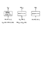
図2は、等価チャンネルを用いた複数チャンネルのためのレート選択を図示したものである。チャンネル応答H(k)と、ノイズ変動N0によって定義される与えられた複数経路チャンネルによって、OFDMシステムは、異なる周波数サブチャンネルに対して異なる変調スキームM(k)を使って、等価なデータレートDequivを達成することができる。このDequivは、特定のチャンネル容量関数f[H(k),N0,M(k)]に基づいて、以下に記載される。個別の周波数サブチャンネルの帯域幅は、1に規格化されているので、関数f[・]の引数として現れない。SNRの推定値であり、望ましいPERであるPeにおける変調スキームMを用いた等価データレートDequivにおいて送信するための等価AWGNチャンネルによって必要とされるSNRequivは、M(k)を用いて、更に、後述する関数g(Dequiv,M(k))に基づいてD equiv のために導出される。
【0030】
データレートD(k)、変調スキームM(k)、及び符号化レートC(k)のために、このAWGNチャンネルは、望ましいPERであるPeを達成するために、SNRであるSNRthか、それ以上を必要とする。この閾SNRthは、コンピュータシミュレーションまたは他の手段によって決定される。メトリック(すなわち、SNRequiv)がSNRthと等しいか、それ以上である場合には、このデータレートD(k)は、その後、複数経路チャンネルのためにOFDMシステムによってサポートされているものと考えられる。データレートD(k)が増加すると、H(k)およびN0によって定義された与えられたチャンネル条件のために、閾SNRthは増加する。したがって、OFDMシステムによってサポートされる最大のデータレートは、チャンネル条件によって制限される。与えられた複数経路チャンネルのために、OFDMシステムによってサポートされる最大データレートを決定するために、ここでは、様々なスキームが提供される。そのうちの幾つかを以下に説明する。
【0031】
第1のレート選択スキームでは、メトリックΨが、OFDMシステム内の与えられた複数経路チャンネルにおけるデータ送信のためのパラメータセットを受信し、受信したパラメータに基づいて、複数経路チャンネルに等価なAWGNチャンネルのためのSNRの推定値を提供する。メトリックΨの入力パラメータは、データ送信の処理に関連した一つ以上のパラメータ(例えば変調スキームM(k))と、通信チャンネルに関連した一つ以上のパラメータ(例えばチャンネル応答H(k)とノイズ変動N0)とを含む。上述したように、変調スキームM(k)は、特定のデータレートD(k)に関連している。メトリックΨは、等価AWGNチャンネルのSNRの推定値である(すなわち、Ψ〜SNRequiv)。複数経路チャンネルによってサポートされる最大データレートは、このデータレートに関連した符号化および変調スキームを用いて、望ましいPERであるPeを達成するためにAWGNチャンネルに必要とされ、閾SNRであるSNRthよりも大きいかまたはそれに等しい等価SNRに関連付けられた最大データレートとして決定される。
【0032】
メトリックΨには様々な関数が使用される。そのうちの幾つかを以下に説明する。ある実施例において、メトリックΨは、以下のように定義される。
【数3】
式(3)において、f[H(k),N0,M]は、変調スキームMが、周波数応答がH(k)で、ノイズ変動がN0であるk番目の周波数サブチャンネルで搬送可能な最大データレートを決定する。この関数f[H(k),N0,M]は、後述するように、様々なチャンネル容量関数に基づいて定義される。
【0034】
このパラメータH(k)と、N0は、SNR(k)にマップされる。このシステムに対する合計送信電力Ptotalが固定され、NF個の周波数サブチャンネルに対する送信電力の割り当てが均一で固定されている場合には、各周波数サブチャンネルに対するSNRは、下記(4)式の通り表される。
【数4】
式(4)に示すように、SNR(k)は、関数f[H(k),N0,M]のパラメータの二つであるチャンネル応答H(k)とノイズ変動N0の関数である。
【0036】
式(3)における総和は、NF個の周波数サブチャンネル全てについてF[・]に対して実行され、AWGNチャンネルで送信される等価データレートDequivを提供する。その後、関数g(Dequiv,M)は、変調スキームMを用いて等価データレートDequivで確実に送信するために、AWGNチャンネルで必要とされるSNRを決定する。
【0037】
式(3)は、同一の変調スキームMが、OFDMシステムにおける全てのNF個の周波数サブチャンネルに使用されることを仮定している。この制限は、OFDMシステム内の送信機と受信機において簡素化された処理をもたらすが、性能を犠牲にする。仮に、異なる変調スキームが異なる周波数サブチャンネルに使用された場合、メトリックΨは、下記(5)式のように表される。
【数5】
式(5)に示すように、この変調スキームM(k)は、周波数サブチャンネルのインデクスkの関数である。異なる周波数サブチャンネルに対して異なる変調スキーム及び/又は符号化レートを用いることはまた、「ビットローディング」とも称される。
【0039】
関数f[x]は、集合的にxとして表されるパラメータのセットについて、AWGNチャンネルを介して確実に送信することができるデータレートを決定する。ここでxは、周波数の関数(すなわち、x(k))である。式(5)では、関数f[H(k),N0,M(k)]、但しx(k)={H(k),N0,M(k)}は、変調スキームM(k)が、チャンネル応答H(k)とノイズ変動N0を伴うk番目のサブチャンネル上で搬送することが可能なデータレートを決定する。関数g(f[x(k)],M(k))はその後、f[x(k)]によって決定されたデータレートを搬送するために等価AWGNチャンネルで必要とされるSNRを決定する。式(5)における総和は、その後、NF個の周波数サブチャンネルの全てについてg(f[x(k)],M(k))に対して行われ、等価AWGNチャンネルのためのSNRの推定値であるSNReq u ivを提供する。
【0040】
この関数f[x]は、様々なチャンネル容量関数またはその他の関数あるいは技術に基づいて定義される。システムの絶対容量は、一般には、チャンネル応答H(k)とノイズ変動N0に対して確実に送信される理論的最大データレートとして与えられる。システムの「制限された」容量は、データ送信に使用される特定の変調スキームまたは配置M(k)に依存し、絶対容量よりも低い。
【0041】
ある実施例では、関数F[H(k),N0,M(k)]が、制限されたチャンネル容量関数に基づいて定義され、下記(6)式の通り表される。
【数6】
ここで、Mkは、変調スキームM(k)に関連している。すなわち、変調スキームM(k)は、
【数7】
の配置(例えば、
【数8】
のQAM)に対応している。なお、この配置における
【数9】
点の各々は、Mkビットによって識別される。aiとajとは、
【数10】
の配置における点である。xは、ゼロ平均と1/SNR(k)の変動とを伴った複素ガウシアンランダム変数である。E[・]は、期待演算であって、式(6)における変数xに関して行われる。
【0047】
式(6)に示す制限されたチャンネル容量関数は、閉じた形式の解を持っていない。従って、この関数は、種々の変調スキームおよびSNR値のために数値的に導出される。そして、この結果が、一つ以上のテーブルに格納される。その後、特定の変調スキームとSNRを用いて、この適切なテーブルにアクセスすることによって関数f[x]が評価される。
【0048】
別の実施例では、関数f[x]は、Shannon(または理論的な)チャンネル容量関数に基づいて定義され、
【数11】
のように表される。ここでWは、システム帯域幅である。上記(7)式に示すように、Shannonチャンネル容量は、如何なる変調スキーム(すなわち、M(k)は、式(7)のパラメータではない)によっても制限されない。
【0050】
f[x]のために使用する特定の関数の選択は、OFDMシステム設計のような種々の要因に依存する。一つ以上の具体的な変調スキームを使用する典型的なシステムのために、式(3)で示されたように定義された行列Ψは、式(6)に示す関数f[x]のための制限されたチャンネル容量とともに連携して使用された場合、複数経路チャンネル用同様に、AWGNチャンネル用のOFDMシステムのためにサポートされた最大のデータレートの正確な推定であることがわかった。
【0051】
関数g(f[x],M(k))は、等価データレートをサポートするためにAWGNチャンネルで必要とされるSNRを決定する。関数gは、変調スキームM(k)を用いて関数f[x]によって決定される。ある実施例では、g(f[x],M(k))は、式(8)の通り定義される。
【数12】
関数f[x]は、変調スキームM(k)に依存するので、関数g(f[x],M(k))もまた変調スキームに依存する。ある実行例において、関数f[x]−1は、使用するために選択され、それぞれのテーブルに格納される各変調スキームのために導出される。この関数g(f[x],M(k))は、その後、変調スキームM(k)のための具体的なテーブルにアクセスすることによって、f[x]の与えられた値のために評価される。関数g(f[x],M(k))は、他の関数を用いて定義することもできる。あるいは、他の手段によって導出される。これは、本発明の範囲内である。
【0053】
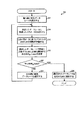
図3は、メトリックΨに基づいてOFDMシステムで使用されるデータレートを選択するプロセス200の実施例のフロー図である。まず、利用可能なデータレート(すなわち、OFDMシステムによってサポートされたもの)がD(0)<D(1)<・・・<D(NR−1)になるように規定される。その後、ステップ212において、最も高い利用可能なデータレートが(例えば、最も高いデータレートのためのインデクスに対してレート変数を設定することによって、あるいはレート=NR−1と設定することによって)選択される。ステップ214では、変調スキームM(rate)のように、選択されたデータレートD(rate)に関連する種々のパラメータが決定される。OFDMシステムの設計に依存して、各データレートは、一つまたは複数の変調スキームに関連付けられている。その後、選択されたデータレートの変調スキームの各々は、以下のステップに基づいて評価される。簡略のため、以下では、唯一の変調スキームが各データレートと関連していると仮定する。
【0054】
このメトリックΨは、その後、ステップ216において、選択されたデータレートDに関連した特定の変調スキームM(rate)について評価される。これは、式(3)に示すように、このメトリックのための関数を評価することによって達成される。
【数13】
このメトリックΨは、変調スキームM(rate)を用いて等価データレートを確実に送信するために等価AWGNチャンネルで必要とされるSNRの推定値を表している。
【0056】
その後、ステップ218では、AWGNチャンネルにおいて望ましいPERであるPeを用いて、選択されたデータレートD(rate)を送信するために必要な閾SNRであるSNRth(rate)が決定される。この閾SRNth(rate)は、変調スキームM(rate)と、この選択されたデータレートに関連した符号化レートC(rate)との関数である。この閾SNRは、可能なデータレートのおのおのについて、コンピュータシミュレーションによって、あるは他の手段によって決定され、後の利用のために格納される。
【0057】
次に、ステップ220では、このメトリックΨが、選択されたデータレートに関連した閾SNRth(rate)以上であるか否かが判定される。メトリックΨが、複数経路チャンネルにおけるデータレートD(rate)のためにOFDMシステムによって達成されたSNRが、望ましいPERであるPeを達成するに十分であることを示すSNRth(rate)以上である場合には、ステップ224において、このデータレートが、使用のために選択される。さもなければ、ステップ222において、次に低い利用可能なデータレートが選択され評価される(例えば、このレート変数を1ずつデクリメントすること、すなわち、rate=rate−1とすることによって)。次に低いデータレートは、その後、ステップ214に戻ることによって評価される。ステップ214からステップ222は、サポートされた最大データレートが認識され、ステップ222において提供されるまで必要に応じて繰り返される。
【0058】
このメトリックΨは、データレートの単調関数であり、データレートの増加と共に増加する。閾SNRもまたデータレートの増加と共に増加する単調関数である。図3に示す実施例は、利用可能なデータレートを、最大の利用可能なデータレートから、最小の利用可能なデータレートへと一度に一つ評価する。メトリックΨよりも小さいかまたはそれに等しい閾SNRであるSNRth(rate)に関連している最も高いデータレートが、使用のために選択される。
【0059】
別の実施例では、このメトリックΨは、等価AWGNチャンネルのためのSNRであるSNRequiv(r)の推定を導出するために、特定の変調スキームM(r)のために評価される。その後、変調スキームM(r)を用いて、等価SNRにおける望ましいPERのためにAWGNチャンネルによってサポートされている最大データレートDmax(r)が、決定される(例えば、ルックアップテーブルによって)。複数経路チャンネルのためにOFDMシステムで使用される実際のデータレートは、その後、AWGNチャンネルでサポートされている最大のデータレートD(r)よりも低いかまたはそれに等しくなるように選択される。
【0060】
第2のレート選択スキームでは、メトリックΨは、等化後に単一のキャリアシステムによって複数経路チャンネルのために達成された検出後SNRとして定義される。この検出後SNRは、受信機における等化後の信号出力対ノイズ及び干渉の比の合計を表している。単一のキャリアシステムで均等化によって達成された検出後SNRの理論値は、OFDMシステムの性能を表しており、OFDMシステムでサポートされた最大のデータレートを決定するために使用される。種々のタイプの等化器が、単一のキャリアシステムにおける受信信号を処理し、複数経路チャンネルによって導入された受信信号における歪みを補償するために使用される。そのような等化器は、例えば、最小平均平方誤差線形等化器(MMSE−LE)、判定フィードバック等化器(DFE)、およびその他を含む。
【0061】
(無限長さ)MMSE−LEのための検出後SNRは、以下のように表される。
【数14】
ここで、Jminは、以下のように表される。
【数15】
また、X(ejwt)は、チャンネル伝達関数H(f)のホールドされたスペクトルである。
【0064】
(無限長さ)DFEのための検出後SNRは、以下のように表される。
【数16】
式(9)および式(10)にそれぞれ示されるMMSE−LEおよびDFEのための検出後SNRは、理論値を表す。MMSE−LEおよびDFEのための検出後SNRはまた、"Digital Communications" 3rd Edition, 1995, McGraw Hill, sections 10-2-2 および10-3-2、J.G. Proakis著(非特許文献1)に更に詳細に記載されている。これは、本明細書で引用して援用している。
【0066】
MMSE−LEおよびDFEのための検出後SNRはまた、特許文献1乃至3に記載されているように、受信信号に基づいて受信機においても評価される。これらは全て本出願の譲受人に譲渡されており、本明細書で引用して援用している。
【0067】
式(9)および式(10)に示すように、解析式で表現される検出後SNRは、複数経路チャンネルのために決定され、メトリックΨの推定値(すなわち、Ψ〜SNRmmse−leまたはΨ〜SNRdfe)として使用される。等価AWGNチャンネルのための検出後SNR(例えばSNRmmse−leまたはSNRdfe)は、特定のパラメータセットD(r)、M(r)、C(r)、及びPeについて導出される閾SNRであるSNRthと比較され、複数経路チャンネルのためにOFDMシステムに使用されるデータレートが判定される。
【0068】
このメトリックΨは、他の関数に基づいても定義され、等価データレートもまた、他の技術に基づいて推定される。これは、本発明の範囲内である。
【0069】
メトリックΨに基づいてOFDMシステムにおける使用のために選択されたデータレートは、望ましいPERであるPeのための複数経路チャンネルによってサポートされているデータレートの予測を表している。任意のレート予測スキームの場合、必然的に予測誤りが生じる。望ましいPERが達成されることを保証するために、この予測誤りが推定され、複数経路チャンネルによってサポートすることができるデータレートの決定にバックオフファクタが使用される。このバックオフは、OFDMシステムのスループットを減らす。従って、望ましいPERを達成しながら、このバックオフをできる限り小さく保つことが望ましい。
【0070】
本発明の別の局面に従うと、バックオフの量を減らし、システムスループットを改善するために、増分送信(IT)スキームが提供され、第1の局面のレート選択と連携して有利に使用される。このITスキームは、一つ以上の離散的な送信、一度に一つの送信、および特定の限界までの一つの送信を使って、与えられたパケットを送信する。パケットのための第1の送信は、十分なデータ量を含んでいる。これによって、パケットは、予期されたチャンネル条件に基づいて、受信機において、誤り無く復元される。しかしながら、この第1の送信が、通信チャンネルによって大幅に品質が低下し、誤りの無いパケットの復元が達成されない場合には、パケットのための追加データ量の増分送信がなされる。その後、受信機は、この増分送信における追加データと、パケットのために以前に受信された全てのデータとに基づいて、パケットの復元を試みる。送信機による増分送信と、受信機による復号は、パケットが誤り無く復元されるか、増分送信の最大数に達するまで、一度以上行われる。
【0071】
このITスキームの実施例は、以下のように実施される。第一に、パケットのためのデータが、増分送信の無いパケットのために使用される符号化レートよりも低い符号化レート(順方向誤り訂正符号用の)を使って符号化される。次に、パケットのための符号化ビットの幾つかがパンクチャされ、全ての符号化ビットのサブセットのみが、パケットの第1の送信のために送信される。このパケットが正しく受信された場合には、受信機は、このパケットが誤り無く受信されたことを示す承認(ACK)を送り返す。一方、受信機は、このパケットを誤って受信した場合には、非承認(NACK)を送り返す。
【0072】
いずれにせよ、このパケットに対する承認が送信機によって受信されなかった場合、または、非承認が受信された場合には、送信機は、受信機に対して増分パケットを送る。この増分パケットは、第1の送信で送られなかったオリジナルのパンクチャされた符号化ビットの幾つかを含みうる。受信機は、その後、第2の送信だけでなく、第1および第2の両方の送信で送られた符号化ビットを使って、パケットを復号するように試みる。第2の送信からの追加符号化ビットは、より多くのエネルギーを与え、誤り訂正能力を改善する。一つ以上の増分送信が実行される。これは、一般的に、承認が受信されるか、または非承認が受信されないまで、一度に一回なされる。増分送信が、このシステムによって適用されたならば、レート予測誤りのためにより小さなバックオフが使用され、よりアグレッシブなレート選択がなされうる。これは、システムスループットの改善の結果をもたらす。
【0073】
上述したレート選択と組み合わせた増分送信もまた、固定またはゆっくりと変化する通信チャンネルによってサポートされた最大データレートを決定する効率的なメカニズムを提供する。チャンネルの複数経路プロファイルがゆっくりと変化する固定アクセスアプリケーションを考える。この場合、初期のデータレートは、上述した技術に基づいて選択され、データ送信のために使用される。仮に、この初期のデータレートが、チャンネルがサポートできるものよりも高い場合には、このITスキームは、パケットが受信機において正しく復号されるまで追加の符号化ビットを送信することができる。その後、チャンネルがサポートできる最大データレートは、第1の送信とそれに続く増分送信で送られた符号化ビットの合計数に基づいて決定される。もしもチャネルがゆっくり変化するならば、この決定されたデータレートは、新しいデータレートが決定される時、すなわちチャンネルが変化するまで使用される。
【0074】
従って、増分送信は、多くの利点をもたらす。第一に、増分送信を使用することによって、アグレッシブなデータレート選択が、システムスループットを増加させることが可能となる。第二に、増分送信は、任意のレート予測スキーム(適用されたバックオフの量に依存した予測誤りの周波数と大きさを伴う)に対して必然的に発生する予測誤りを救済する手段を提供するそして第三には、増分送信は、固定またはゆっくりと変化するチャンネルのためにサポートされた最大データレートをより正確に決定するためのメカニズムを提供する。
【0075】
図4は、送信機システム110aと受信機システム150aの実施例のブロック図である。これらは、本発明の種々の局面および実施例を実現することができる。
【0076】
送信機システム110aでは、トラフィックデータが、特定のデータレートで、データソース308から送信(TX)データプロセッサ310へと与えられる。このプロセッサ310は、符号化データを提供するために、特定の符号化スキームに基づいてこのトラフィックデータをフォーマットし、インタリーブし、符号化する。このデータレートと符号化は、コントローラ330によって提供されるデータレートコントロールと符号化コントロールによってそれぞれ決定される。この符号化されたデータは、その後、変調器320に提供される。変調器320はまたパイロットデータ(例えば、公知のパターンからなり、公知の手法で処理されたデータ)を受信する。このパイロットデータは、トラフィックデータを送信するために使用された周波数サブチャンネルの全てあるいはサブセット内の符号化トラフィックデータを用いて、例えば、時分割多重化(TDM)または符号分割多重化(CDM)を使って多重化される。ある具体的な実施例では、OFDMのために、変調器320による処理は、(1)受信データを一つ以上の変調スキームで変調することと、(2)この変調されたデータを変換してOFDMシンボルを形成することと、(3)周期的なプレフィクスを各OFDMシンボルに追加し、対応する送信シンボルを形成することとを含んでいる。この変調は、コントローラ330によって提供される変調コントロールに基づいて実行される。この変調されたデータ(すなわち、送信シンボル)は、その後、送信機(TMTR)322に提供される。
【0077】
送信機322は、この変調されたデータを、一つ以上のアナログ信号に変換し、更にこのアナログ信号を処理(例えば、増幅、フィルタ、直交変調)し、通信チャンネルを介して送信するのに適した変調信号を生成する。この変調された信号は、その後、アンテナ324を経由して受信機システムへと送信される。
【0078】
受信機システム150aでは、送信された変調信号がアンテナ352によって受信され、受信機(RCVR)354に提供される。受信機354は、この受信信号を処理(例えば、フィルタ、増幅、およびダウンコンバート)し、データサンプルを提供するためにこの処理した信号をデジタル化する。そして、復調器(Demod)360は、復調データを提供するために、このデータサンプルを処理する。OFDMのために、復調器360による処理は、(1)各OFDMシンボルに以前追加された周期的なプレフィックスを取り除くことと、(2)復元された各OFDMシンボルを変換することと、(3)復元された変調シンボルをこの送信システムで使用されている一つ以上の変調スキームに相補的な一つ以上の復調スキームにしたがって復調することと
を含んでいる。
【0079】
その後、受信(RX)データプロセッサ362が、送信されたトラフィックデータを復元するために、復調されたデータを復号する。復調器360とRXデータプロセッサ362による処理は、送信機システム110aにおいて変調器320およびTXデータプロセッサ310のそれぞれによって実行されるものに対して相補的である。
【0080】
図4に示すように、復調器360は、チャンネル応答H(k)の推定値を導出し、これら推定値をコントローラ370に提供する。RXデータプロセッサ362は、受信された各パケットのステータスの導出と、提供とも行う。更に、復号結果を示す他の一つ以上の性能メトリックを提供する。復調器360およびRXデータプロセッサ362から受信された様々な情報の種類に基づいて、コントローラ370は、上述した技術に基づいて、データ送信のための特定のレートを決定または選択する。選択されたレートの形態によるフィードバック情報、チャンネル応答推定値、受信パケットについてのACK/NACK等は、コントローラ370によって提供され、TXデータプロセッサ378によって処理され、変調器380によって変調され、送信機354によって処理され、更に、送信機システム110aへと返信される。
【0081】
送信機システム110aでは、受信機システム150aからの変調信号は、受信機システムによって送信されたフィードバック情報を復元するために、アンテナ324によって受信され、受信機322によって処理され、復調器340によって復調される。その後、このフィードバック情報は、コントローラ330へ提供され、受信機システムへのデータ送信の処理を制御するために使用される。例えば、データ送信のデータレートは、受信機システムによって提供される選択レートに基づいて決定されるか、受信機システムからのチャンネル応答推定値に基づいて決定される。この選択されたレートに関連付けられた特定の符号化及び変調スキームが決定され、TXデータプロセッサ310および変調器320に提供された符号化及び変調コントロールに反映される。受信されたACK/NACKは、増分送信を初期化するために使用される(簡略化のために図4には示されていない)。
【0082】
コントローラ330およびコントローラ370は、この操作を、送信機システムおよび受信機システムへとそれぞれ導く。メモリ332とメモリ372は、それぞれコントローラ330およびコントローラ370によって使用されるプログラムコードとデータとを格納する。
【0083】
図5は、送信機ユニット400のブロック図である。これは、送信機システム110aのうちの送信機部分の実施例である。送信機ユニット400は、(1)符号化データを提供するためにトラフィックデータを受信し、処理するTXデータプロセッサ310aと、(2)変調データを提供するために符号化データを変調する変調器320aとを含む。TXデータプロセッサ310aおよび変調器320aは、それぞれTXデータプロセッサ310および変調器320の一実施例である。
【0084】
図5に示す具体的な実施例では、TXデータプロセッサ310aは、エンコーダ412、チャンネルインタリーバ414、およびパンクチャ部416を含む。エンコーダ412は、符号化ビットを提供するために、一つ以上の符号化スキームに従ってトラフィックデータを受信し、符号化する。この符号化は、データ送信の信頼性を増大させる。各符号化スキームは、CRC符号化、畳み込み符号化、ターボ符号化、ブロック符号化、およびその他の符号化の任意の組み合わせ、または全く符号化しないことを含む。トラフィックデータは、パケット(またはフレーム)に仕切られる。そして各パケットは、個別に処理され送信される。ある実施例では、各パケットについて、パケット内のデータがCRCビットのセットを生成するために使用される。これは、データに追加され、このデータ及びCRCビットが、その後、畳み込み符号またはターボ符号によって符号化されて、パケットについて符号化されたデータが生成される。
【0085】
その後チャンネルインタリーバ414が、ダイバーシティを提供するために、特定のインタリーブスキームに基づいて、符号化ビットをインタリーブする。このインタリーブは、符号化ビットのために時間ダイバーシティを提供し、データ送信に使用される周波数サブチャンネルに対する平均SNRに基づいて、データが送信されることを許可し、フェージングと格闘し、各変調シンボルの生成のために使用される符号化ビット間の相関関係を取り除く。仮に、符号化ビットが、多数の周波数サブチャンネルを介して送信される場合には、このインタリーブは、更に周波数ダイバーシティを提供する。
【0086】
その後、パンクチャ部416は、このインタリーブされた符号化ビットのうちのゼロまたはそれ以上をパンクチャ(すなわち、削除)し、要求された数のパンクチャされていない符号化ビットを、変調器320aに提供する。パンクチャ部416は、更に、パンクチャした符号化ビットをバッファ418に提供する。バッファ418は、上述したように、後の時間における増分送信のために必要とされる場合には、これら符号化ビットを格納する。
【0087】
図5に示す具体的な実施例では、変調器320aは、シンボルマッピング要素422と、IFFT424と、周期的プレフィックス生成器426とを含む。シンボルマッピング要素422は、多重化されたパイロットデータと、符号化されたトラフィックデータとをデータ送信に使用される一つ以上の周波数サブチャンネルのための変調シンボルへとマップする。変調コントロールによって示されるように、一つ以上の変調スキームが、周波数サブチャンネルのために使用される。使用するために選択された各変調スキームのために、変調は、マルチビットシンボルを形成するために受信ビットのセットをグループ化し、選択された変調スキーム(例えば、QPSK、M−PSK、M−QAM、またはその他のスキーム)に対応した信号配置における点に各マルチビットシンボルをマップすることによって達成される。マップされた各信号点は、変調シンボルに対応している。その後、シンボルマッピング要素422は、各送信シンボル周期に対して(NF 個までの)変調シンボルのベクトルを、送信シンボル周期の使用のために選択された周波数サブチャンネルの数(NF 個まで)に対応する各ベクトルの変調シンボルの数とともに提供する。
【0088】
IFFT424は、各変調シンボルベクトルを、逆高速フーリエ変換を用いて、時間ドメイン表示(OFDMシンボルと称される)に変換する。IFFT424は、任意の数の周波数サブチャンネル(例えば、8,16,32,・・・,NF,・・・)について逆変換を行うように設計される。ある実施例では、各OFDMシンボルについて、周期的プレフィックス生成器426が、OFDMシンボルの一部を繰り返し、対応する送信シンボルを生成する。この周期的プレフィックスは、送信シンボルが、複数経路遅延拡散が存在する直交特性を保持することを保証し、これによって、悪影響のある経路効果に対する性能を改善する。周期的プレフィックス生成器426からの送信シンボルは、その後、送信機322に提供され(図4参照)、変調信号を生成するために処理される。この変調信号は、その後、アンテナ324から送信される。
【0089】
送信機ユニットのための他の設計もまた、適用され、これもまた本発明の範囲内である。エンコーダ412、チャンネルインタリーバ414、パンクチャ部416、シンボルマッピング要素422、IFFT424、及び周期的プレフィックス生成器426は、当該技術分野で知られており、ここでは詳細について記載しない。
【0090】
OFDMおよび他のシステムのための符号化及び変調は、前記した特許文献1乃至3、"Coding Scheme for a Wireless Communication System"と題された米国特許出願番号 第09/776,075号(2001年2月1日出願)(特許文献4)、および"Multiple- Access Multiple-Input Multiple-Output (MIMO) Communication System"と題された米国特許出願番号 Attorney Docket No. 010254(2001年11月6日出願)(特許文献5)に更なる詳細が記載されている。これらは全て本出願の譲受人に譲渡されており、本書で引用して援用している。
【0091】
OFDMシステムの一例は、"High Efficiency, High Performance Communication System Employing Multi-Carrier Modulation"と題された米国特許出願番号 第09/532,492号(2000年3月30日出願)(特許文献6)に記載されている。これは、本発明の譲受人に譲渡されており、本書で引用して援用している。OFDMはまた、"Multicarrier Modulation for Data Transmission: An Idea Whose Time Has Come, "by John A. C. Bingham, IEEE Communications Magazine, May 1990(非特許文献2)に記載されており、本書で引用して援用している。
【0092】
図6は、受信機ユニット500の実施例のブロック図である。これは、図4に示す受信機システム150aの受信機部分の一実施例である。送信機システムから送信された信号は、アンテナ352によって受信され(図4)、受信機354(フロント−エンドプロセッサとも称される)に提供される。受信機354は、この受信信号を処理(例えば、フィルタおよび増幅)し、処理した信号を中間周波数、すなわちベースバンドにダウンコンバートし、ダウンコンバートされた信号をデジタル化してデータサンプルを提供する。このデータサンプルは、復調器360aに与えられる。
【0093】
復調器360a内では(図6)、データサンプルが、周期的プレフィックス除去要素510に提供される。ここは、各送信シンボルに含まれる周期的プレフィックスを除去し、対応する復元されたOFDMシンボルを提供する。その後、FFT512が、高速フーリエ変換を用いて、復元されたOFDMシンボルをおのおの変換し、復元された変調シンボルのベクトル(NF 個まで)を、各送信シンボル周期に対するデータ送信のために使用される(NF 個までの)周波数サブチャンネルのために提供する。FFT512からの復元された変調シンボルは、復調要素514に提供され、送信機システムで使用されている一つ以上の変調スキームと相補的な一つ以上の復調スキームにしたがって復調される。その後、復調要素514からの復調データは、RXデータプロセッサ362aに提供される。
【0094】
RXデータプロセッサ362a内では、復調データが、送信機システムにおいて行われたものと相補的に逆インタリーバ522によって逆インタリーブされる。そして、この逆インタリーブされたデータは更に、送信機システムにおいて行われたものと相補的に復号器524によって復号される。例えば、ターボ符号化または畳み込み符号化がそれぞれ送信機ユニットにおいて実行される場合には、復号器524としてターボ復号器またはViterbi復号器が使用される。復号器524からの復号されたデータは、送信されたデータの推定値を表す。復号器524は、各受信パケットのステータス(例えば、正しく受信されたか誤って受信されたか)を与える。復号器524は、更に、正しく復号されなかったパケットのための復調データを格納する。これによって、このデータは、引き続く増分送信からのデータと結合され、復号される。
【0095】
図6に示すように、チャンネル推定器516は、チャンネル周波数応答
【数17】
と、ノイズ変動
【数18】
とを推定し、これら推定値をコントローラ370に与えるように設計される。このチャンネル応答とノイズ変動とは、パイロットシンボルに対して受信されたデータサンプルに基づいて推定される(例えば、パイロットシンボルについては、FFT512からのFFT係数に基づく)。
【0098】
コントローラ370は、レート選択と、増分送信のためのシグナリングの種々の局面と実施例を実施するように設計されている。レート選択のために、コントローラ370は、上述したようなメトリックに基づいて、与えられたチャンネル条件に使用される最大データレートを決定する。増分送信のために、コントローラ370は、与えられたパケットのために受信された送信の各々のためのACKまたはNACKを提供する。このパケットは、受信機システムにおいて正しく復元できなかった場合には、パケットの追加部分を送信するために送信機システムで使用される。
【0099】
図1と図4とは、受信機が、データ送信のためのレートを送り返すことができる単純な設計を示す。他の設計もまた実施されることができ、これも本発明の範囲内である。例えば、このチャンネル推定値は(レートの代わりに)、送信機へ送信される。この送信機は、その後、この受信チャンネル推定値に基づいて、データ送信のためのレートを決定する。
【0100】
ここで記載されたレート選択と、増分送信技術とは、様々な設計を用いて実施される。例えば、チャンネル推定値を導出し、提供するために使用されている図6に示すチャンネル推定器516は、受信機システム内の様々な要素によって実現される。レートを決定するための処理の幾つかあるいは全ては、コントローラ370によって実行される(例えば、メモリ372に格納された一つ以上のルックアップテーブルを用いて)。レート選択と増分送信を実行するための他の設計もまた考えられ、これもまた本発明の範囲内である。
【0101】
ここで記載されたレート選択と増分送信は、種々の手段によって実施される。例えば、これらの技法は、ハードウェア、ソフトウェア、またはこれらの組み合わせで実施されうる。ハードウェア実装のために、レート選択及び/又は増分送信を行うために使用される要素の幾つかは、一つ以上の特定用途向けIC(ASIC)、デジタル信号プロセッサ(DSP)、デジタル信号処理デバイス(DSPD)、プログラマブルロジックデバイス(PLD)、フィールドプログラマブルゲートアレイ(FPGA)、プロセッサ、コントローラ、マイクロコントローラ、マイクロプロセッサ、上述した機能を実行するために設計された他の電子ユニット、またはこれらの組み合わせの中で実装される。
【0102】
ソフトウェア実装のために、レート選択及び/又は増分送信の部分は、上述した機能を実行するモジュール(例えば、処理、関数等)によって実装される。ソフトウェアコードは、メモリユニット(図4におけるメモリ332またはメモリ372)に格納され、プロセッサ(コントローラ330またはコントローラ370)によって実行される。メモリユニットは、プロセッサ内か、または、プロセッサに外部に実装される。この場合、当該技術分野で知られた種々の手段を経由して通信可能なようにプロセッサに接続されている。
【0103】
前述した実施例の記載によって、当該技術分野における熟練者は、本発明を利用または使用することが可能となる。これらの実施例に対する種々の変形は、当該技術における熟練者には明らかなことであろう。そして、ここで定義された一般的な原理は、本発明の思想または範囲から逸脱することなく他の実施例に適用される。従って、本発明は、ここで示された実施例に限定することを意図しておらず、ここで開示された原理および斬新な特徴と一貫した最も広いスコープが与えられる。
【図面の簡単な説明】
【0104】
【図1】OFDM通信システムの簡略モデルの図である。
【図2】等価チャンネルを用いた複数経路のためのレート選択をグラフィカルに示した図である。
【図3】メトリックTに基づいたOFDMシステムにおいて用いられるデータレートを選択するプロセスの実施例を示すフロー図である。
【図4】本発明の様々な局面と実施例を実行することができる送信システムと受信システムの実施例のブロック図である。
【図5】送信ユニットの実施例を示すブロック図である。
【図6】受信機ユニットの実施例を示すブロック図である。
【符号の説明】
【0105】
110…送信機、110a…送信機システム、112…データソース、114…変調器、116…逆高速フーリエ変換器、130…コントローラ、150…受信機、150a…受信機システム、160…高速フーリエ変換器、162…復号器、164…チャンネル推定器、166…レートセレクタ、170…コントローラ、200…プロセス、308…データソース、310…送信データプロセッサ、320…変調器、322…送信機/送信機、324…アンテナ、330…コントローラ、332…メモリ、340…復調器、352…アンテナ、354…送信機/受信機、360…復調器、362…受信データプロセッサ、370…コントローラ、372…メモリ、378…送信データプロセッサ、380…変調器、400…送信機ユニット、412…エンコーダ、414…チャンネルインタリーバ、416…パンクチャ部、418…バッファ、422…シンボルマッピング要素、424…IFFT、426…周期的プレフィックス生成器、500…受信機ユニット、510…周期的プレフィックス除去要素、512…FFT、514…復調要素、516…チャンネル推定器、522…逆インタリーバ、524…復号器 【Technical field】
[0001]
The present invention relates generally to data communication, and more particularly to wireless (eg, OFDM) communication systems.rateRelates to the technology to select.
[Background]
[0002]
Wireless communication systems are widely applied to provide various types of communication such as voice and data. These systems may apply orthogonal frequency division multiplexing (OFDM) modulation. This can provide high performance for certain channel environments. In an OFDM system, the system bandwidth is large (NF PiecesOf frequency subchannels (this is referred to as subbands or frequency bins). Each frequency subchannel contains datamodulationAssociated with each subcarrier (or frequency tone) to be played. Typically, the transmitted data (ie, information bits) isSignSpecific to generate a normalized bitSignWith schemeCodingIs done. AndSignThe grouped bits are grouped into multi-bit symbols. They are further based on specific modulation schemes (eg M-PSK or M-QAM)TheMaps to modulation symbol. At each time interval depending on the bandwidth of each frequency subchannel, the modulation symbol is NF PiecesFor each of the frequency subchannelsThereforeSent.
[0003]
The frequency subchannel of an OFDM system is subject to different channel conditions (eg, frequencyFadingAnd multipath effects), resulting in different signal-to-noise and interference ratio (SNR). Each transmitted modulation symbol is affected by the frequency response of the communication channel in the particular frequency subchannel through which the transmitted symbol has passed. Depending on the multipath profile of the communication channel, the frequency response can vary significantly over the system bandwidth. Thus, the modulation symbols that collectively generate a particular data packet are NF PiecesAre individually received in a wide range of SNR via the frequency subchannels. And this SNR corresponds to the packetThe entireVaries over time.
[0004]
For multipath channels with frequency response that is neither flat nor constant, each frequency subchannelAboveThe number of information bits per modulation symbol that are transmitted reliably (ie datarateOr informationrate) Differs from subchannel to subchannel. In addition, channel conditions generally vary over time. As a result, for frequency subchannelsInSupported datarateAlso change over time.
[0005]
Experience with a given receiverIsThe channel conditions are not speculatively known, so the same transmission for all receiversElectricForce and / or datarateIt is unrealistic to send data with. Fixing these transmission parameters is the transmissionElectricWasting power, suboptimal data for a given receiverrateAnd the result of unreliable communication to other receivers, all of which result in an undesirable reduction in system capacity. Different receiversForTransmission with different communication channelsabilityAdding to these channels time variations and multipath characteristics is an effective way of transmitting data in an OFDM system.SignIt will be a challenge to make and modulate.
[0006]
Therefore, suitable for data transmission in a wireless (eg OFDM) communication system with channel characteristics as described above.rateThere is a need for technology to choose.
[Patent Document 1]
US Patent Application No. 09 / 826,481, "Method and Apparatus for Utilizing Channel State Information in a Wireless Communication System", filed March 23, 2001
[Patent Document 2]
US Patent Application No. 09 / 956,449, "Method and Apparatus for Utilizing Channel State Information in a Wireless Communication System", filed September 18, 2001
[Patent Document 3]
US Patent Application No. 09 / 854,235, "Method and Apparatus for Processing Data in a Multiple-Input Multiple-Output (MIMO) Communication System Utilizing Channel State Information", filed May 11, 2001
[Patent Document 4]
US Patent Application No. 09 / 776,075, "Coding Scheme for a Wireless Communication System", filed February 1, 2001
[Patent Document 5]
US Patent Application Number Attorney Docket No. 010254 "Multiple-Access Multiple-Input Multiple-Output (MIMO) Communication System", filed November 6, 2001
[Patent Document 6]
US Patent Application No. 09 / 532,492, "High Efficiency, High Performance Communication System Employing Multi-Carrier Modulation", filed March 30, 2000
[Non-Patent Document 1]
"Digital Communications" 3rd Edition, 1995, McGraw Hill, sections 10-2-2 and 10-3-2, by J. G. Proakis
[Non-Patent Document 2]
"Multicarrier Modulation for Data Transmission: An Idea Whose Time Has Come," by John A. C. Bingham, IEEE Communications Magazine, May 1990
DISCLOSURE OF THE INVENTION
Aspects of the invention are for data transmission in a wireless (eg, OFDM) communication system.rateProvide technology to determine and select. These techniques can be used to provide improved system performance for OFDM systems operating on either multipath (non-flat) channels or flat channels.
[0007]
In one aspect, the maximum data that is reliably transmitted over a given multipath channel by the OFDM systemrateIs determined based on a metric for an equivalent frequency flat channel (eg, a channel with a flat frequency response). For a given multipath channel defined by a specific frequency response and a specific noise change, the OFDM system uses a specific modulation scheme M (r) to generate specific equivalent data.rateDequivCan be achieved. Equivalent datarateDequivIs estimated based on a specific channel capacity function (eg, a limited channel capacity function or other function). Equivalent data using modulation scheme M (r)rateDequiv soTo ensure transmission, the metric, which is an estimate of the SNR required by the equivalent frequency flat channel, uses M (r)Furthermore,A specific function g (Dequiv, M (r))D equiv Determined forThe After that, the modulation scheme M (r)SignConversionrateSpecific data using C (r)rateD (r)soThe threshold SNR required for the equivalent channel to reliably transmit is determined. If the metric is greater than or equal to this threshold SNR, this datarateD (r) is considered supported by the multipath channel.
[0008]
In another aspect, an incremental transmission (IT) scheme is provided and the first aspect ofrateBy coordinating with selection, it is advantageously used to reduce the amount of backoff and improve system throughput. This IT scheme isSend one transmission at a time up to a certain controlOne or more discrete transmissionsmake use of, Send the given data packet. The first transmission for this packet contains a sufficient amount of data. This allows packets to be received at the receiver based on expected channel conditions.errorWithoutRestorecan do. However, the quality of this first transmission is greatly reduced by the communication channel,errorOf packets withoutRestoreIf this is not achieved, an incremental transmission of an additional amount of data for the packet is made. The receiver then sends a packet based on the additional data in the incremental transmission and all the data previously received for the packet.RestoreTry to do. Incremental transmission by transmitter and by receiverDecryptionThe packet iserrorWithoutRestoreOr more than once until the maximum number of incremental transmissions is reached.
[0009]
Various aspects and examples of the invention are described in detail below. The present invention further includes methods, receiver units, transmitter units, receiver systems, transmitter systems, systems, and other devices that implement various aspects, embodiments, and features of the present invention as described below. And providing components.
BEST MODE FOR CARRYING OUT THE INVENTION
[0010]
The features, characteristics, and advantages of the present invention will become apparent from the following detailed description, taken in conjunction with the drawings, in which like reference characters correspond.
[0011]
For data transmissionrateThe techniques described herein for determining and selecting are used for various wireless communication systems consisting of one or more independent transmission channels, eg, multiple input multiple output (MIMO) systems. . For clarity, various aspects and embodiments of the invention are specifically described for an Orthogonal Frequency Division Multiplexing (OFDM) system. In this system, independent transmission channels areoverallA frequency subchannel or bin formed by dividing the system bandwidth.
[0012]
FIG. 1 is a diagram of a simplified model of an OFDM system. At the
[0013]
In some embodiments, this datarateThe datarateDetermined by control,SignThe conversion scheme isSignThe modulation scheme is determined by the modulation control. All of this is provided by the
[0014]
The pilot also has channel estimation,capture, Frequency andtimingSent to the receiver to assist in performing many functions such as synchronization, coherent data demodulation, etc. In this case, pilot data is provided to encoder /
[0015]
For OFDM, this modulation data (ie, modulation symbols) is then converted to the time domain by an inverse fast Fourier transformer (IFFT) 116, and OFDM symbolsButProvided. Here, each OFDM symbol is represented by N within a transmission symbol period.F PiecesN transmitted on frequency subchannelF PiecesSupports time display of modulation symbol vector. Single carrier 'timeSignCompared to a "systemized" system, an OFDM system efficiently transmits modulation symbols "in the frequency domain" by sending an IFFT of modulation symbols representing traffic data in the time domain. This OFDM symbol is further processed (not shown in FIG. 1 for simplicity) to generate a modulated signal.This modulated signal isThen, it is transmitted to the receiver via the wireless communication channel. As shown in FIG. 1, this communication channel has a frequency response H (F), and further uses n (t) additional white Gaussian noise (AWGN) to generate a modulated signal.InferiorityLet me down.
[0016]
At the
[0017]
[0018]
[0019]
In the embodiment shown in FIG.rateThe selection is performed by the
[0020]
Under appropriate conditions, output to FFT160And restoreThe performed OFDM symbol is expressed as the following equation (1).
[Expression 1]
Here, k is the index of the frequency subchannel of the OFDM system, that is, k = 0, 1,.F−1 and NFIs the number of frequency subchannels. Y (k) is a modulation symbol transmitted on the kth frequency subchannel. These are derived based on the specific modulation scheme used for the kth frequency subchannel. H (k) is the frequency response of the communication channel and is displayed in a “quantized” format for each frequency subchannel. N (k) is the time domain noise NFAn FFT of a sequence of samples is shown. That is, k = 0, 1,..., NFFFT {n (kT)} in the case of -1. T is a sampling period.
[0022]
In a single carrier system, the transmitted symbols are all received at the receiver with almost the same SNR. SNR of the “constant SNR” packet and the packeterrorThe relationship with the probability is well known in the art. As an approximation, the maximum data supported by a single carrier system with a particularly achieved SNRrateIs the maximum data supported by the AWGN channel with the same SNRrateIt is estimated to be. The main characteristic of the AWGN channel is that the frequency response is flat, i.e. constant over the entire system bandwidth.
[0023]
However, in an OFDM system, the modulation symbols that make up a packet are transmitted over multiple frequency subchannels. Depending on the frequency response of the frequency subchannel being used to transmit the packet, the SNR can vary across the packet. The problem of packets that change the SNR is exacerbated as the system bandwidth increases and experiences multiple paths.
[0024]
A major challenge for OFDM systems is the specific packeterrorRate (PER), frameerrorRate (FER), biterrorMaximum data used for data transmission while achieving a specific performance level quantified by rate (BER) or other criteriarateIs to decide. For example, the desired level of performance is achieved by maintaining the PER within a small window around a specific nominal value (eg, Pe = 1%).
[0025]
In a typical communication system, specific and discrete datarateThis set of data is definedrateOnly use is valid. Each datarateD (r) is a specific modulation scheme or configuration M (r) and a specificSignConversionrateRelated to C (r). Each datarateRequires a more specific SNR (r). This is the minimum SNR, where this datarateThe resulting PER for data transmission at is less than or equal to the desired PER, Pe. This SNR (r) assumes that the communication channel is AWGN (ie, has a flat frequency response over the entire system bandwidth, ie, H (k) = H holds for all k). In general, the communication channel between the transmitter and the receiver is not AWGN but is distributed or frequency selective (ie, different attenuation in different subbands of system bandwidth). For such multi-path channels, the specific data used for data transmissionrateAre selected because of the multipath or frequency selective nature of the channel.
[0026]
Each datarateD (r) is associated with the parameter set that characterizes it. These parameters are represented by modulation scheme M (r), as shown in equation (2) below:SignConversionrateC (r), and the desired SNR (r).
[Expression 2]
Where r is the datarate, I.e., r = 0, 1,..., NR−1 and NR(Subscript) is available datarateoftotalIs a number. Equation (2) is datarateD (r) is the modulation scheme M (r)SignConversionrateIt states that SNR (r) is required for the AWGN channel to be transmitted using C (r) and to achieve the desired nominal PER Pe. NR PiecesdatarateD (0) <D (1) <D (2) <... <D (NR-1) is required.
[0028]
According to an aspect of the present invention, maximum data that is reliably transmitted over a given multipath channel in an OFDM system.rateIs determined based on a metric for an equivalent AWGN channel. Reliable transmission is achieved when the desired PER, Pe, is maintained for this data transmission. Details of this aspect are shown below.
[0029]
Figure 2 is for multiple channels with equivalent channelsrateThe selection is illustrated. Channel response H (k) and noise fluctuation N0With a given multipath channel defined by, the OFDM system uses different modulation schemes M (k) for different frequency subchannels, and equivalent datarateDequivCan be achieved. This DequivIs a specific channel capacity function f [H (k), N0, M (k)] is described below. Individual frequency subchannel bandwidthIsSince it is normalized to 1, it does not appear as an argument of the function f [•]. Pe, which is an estimate of SNR and is the desired PERModulation scheme M inUsingTheEquivalent datarateDequivRequired by the equivalent AWGN channel for transmission atequivIs a function g (D) to be described later using M (k).equiv, M (k))D equiv Derived forThe
[0030]
datarateD (k), modulation scheme M (k), andSignConversionrateFor C (k), this AWGN channel is SNR, which is the SNR, to achieve the desired PER, Pe.thOr need more. This threshold SNRthIs determined by computer simulation or other means. Metric (ie, SNRequiv) Is SNRthThis data is equal to or greater thanrateD (k) is then considered supported by the OFDM system for multipath channels. datarateAs D (k) increases, H (k) and N0Threshold SNR for a given channel condition defined bythWill increase. Therefore, the maximum data supported by the OFDM systemrateIs limited by channel conditions. Maximum data supported by the OFDM system for a given multipath channelrateHere, various schemes are provided. Some of them are described below.
[0031]
FirstrateIn the selection scheme, the metric Ψ is the OFDM systemInsideA parameter set for data transmission in a given multi-path channel is received, and an SNR estimate for the AWGN channel equivalent to the multi-path channel is provided based on the received parameters. The input parameters of the metric Ψ include one or more parameters related to the process of data transmission (eg modulation scheme M (k)) and one or more parameters related to the communication channel (eg channel response H (k) and noise). Fluctuation N0). As mentioned above, the modulation scheme M (k)rateIs related to D (k). The metric Ψ is an estimate of the SNR of the equivalent AWGN channel (ie, Ψ˜SNRequiv). Maximum data supported by multipath channelsrateThis datarateRelated toSignSNR is the threshold SNR required for the AWGN channel to achieve the desired PER, using an optimization and modulation schemethGreater than or equal to the equivalent SNRBigdatarateAs determined.
[0032]
Various functions are used for the metric Ψ. Some of them are described below. In one embodiment, the metric Ψ is defined as follows:
[Equation 3]
In Formula (3), f [H (k), N0, M] is the modulation scheme M, the frequency response is H (k), and the noise variation is N0Maximum data that can be carried on the kth frequency subchannelrateTo decide. This function f [H (k), N0, M] are defined based on various channel capacity functions, as will be described later.
[0034]
This parameter H (k) and N0Is mapped to SNR (k). For this systemtotalSendElectricForce PtotalIs fixed, NFTransmit on frequency subchannelsElectricWhen the force allocation is uniform and fixed, the SNR for each frequency subchannel is expressed by the following equation (4).
[Expression 4]
As shown in equation (4), SNR (k) is a function f [H (k), N0, M] are channel parameters H (k) and noise fluctuation N0Is a function of
[0036]
The sum in equation (3) is NFEquivalent data executed on F [•] for all frequency subchannels and transmitted on the AWGN channelrateDequivI will provide a. After that, the function g (Dequiv, M) is equivalent data using the modulation scheme MrateDequivIn order to ensure transmission, the SNR required in the AWGN channel is determined.
[0037]
Equation (3) shows that the same modulation scheme M is applied to all N in the OFDM system.FIt is assumed that it is used for frequency subchannels. thisSystemThe limitations result in simplified processing at the transmitter and receiver in the OFDM system, but at the expense of performance. If different modulation schemes are used for different frequency subchannels, the metric Ψ is expressed by the following equation (5).
[Equation 5]
As shown in equation (5), this modulation scheme M (k) is a function of the frequency subchannel index k. Different modulation schemes and / or for different frequency subchannelsSignConversionrateUsing is also referred to as “bit loading”.
[0039]
The function f [x] is data that can be reliably transmitted over the AWGN channel for a set of parameters collectively represented as x.rateTo decide. Here, x is a function of frequency (ie, x (k)). In equation (5), the function f [H (k), N0, M (k)], where x (k) = {H (k), N0, M (k)} indicates that the modulation scheme M (k) has a channel response H (k) and noise variation N0On the kth subchannel withsoData that can be transportedrateTo decide. The function g (f [x (k)], M (k)) is then the data determined by f [x (k)].rateTo determine the SNR required in the equivalent AWGN channel. The sum in equation (5) is then NFSNR, which is an estimate of the SNR for the equivalent AWGN channel, performed on g (f [x (k)], M (k)) for all frequency subchannelseq u ivI will provide a.
[0040]
This function f [x] is defined based on various channel capacity functions or other functions or techniques. The absolute capacity of the system is generally determined by the channel response H (k) and the noise variation N0Maximum theoretical data transmitted reliablyrateAs given. The “limited” capacity of the system depends on the specific modulation scheme or arrangement M (k) used for data transmission and is lower than the absolute capacity.
[0041]
In one embodiment, the function F [H (k), N0, M (k)] is defined based on the limited channel capacity function, and is expressed as the following equation (6).
[Formula 6]
Where MkIs related to the modulation scheme M (k). That is, the modulation scheme M (k) is
[Expression 7]
Placement (e.g.,
[Equation 8]
QAM). In this arrangement
[Equation 9]
Each of the points is MkIdentified by a bit. aiAnd ajIs
[Expression 10]
It is a point in the arrangement of. x is a complex Gaussian random variable with zero mean and 1 / SNR (k) variation. E [•] is an expectation operation, and is performed for the variable x in Equation (6).
[0047]
The limited channel capacity function shown in equation (6) does not have a closed form solution. This function is therefore derived numerically for various modulation schemes and SNR values. This result is stored in one or more tables. The function f [x] is then evaluated by accessing this appropriate table using a particular modulation scheme and SNR.
[0048]
In another embodiment, the function f [x] is defined based on a Shannon (or theoretical) channel capacity function,
## EQU11 ##
It is expressed as Where W is the system bandwidth. As shown in equation (7) above, Shannon channel capacity is not limited by any modulation scheme (ie, M (k) is not a parameter of equation (7)).
[0050]
The selection of a particular function to use for f [x] depends on various factors such as the OFDM system design. For a typical system using one or more specific modulation schemes, the matrix Ψ defined as shown in equation (3) is for the function f [x] shown in equation (6). Maximum data supported for OFDM systems for AWGN channels as well as for multipath channels when used in conjunction with a limited channel capacity ofrateWas found to be an accurate estimate of
[0051]
The function g (f [x], M (k)) is equivalent datarateTo determine the SNR required on the AWGN channel.Function gIs determined by the function f [x] using the modulation scheme M (k). In one embodiment, g (f [x], M (k)) is defined as in equation (8).
[Expression 12]
Since the function f [x] depends on the modulation scheme M (k), the function g (f [x], M (k)) also depends on the modulation scheme. In an execution example, the function f [x]-1Are derived for each modulation scheme that is selected for use and stored in a respective table. This function g (f [x], M (k)) is then evaluated for a given value of f [x] by accessing a specific table for the modulation scheme M (k). Is done. The function g (f [x], M (k)) can also be defined using other functions. Alternatively, it is derived by other means. This is within the scope of the present invention.
[0053]
FIG. 3 shows data used in an OFDM system based on the metric ΨrateFIG. 3 is a flow diagram of an example of a
[0054]
This metric Ψ is then determined in step 216 by the selected datarateIt is evaluated for a particular modulation scheme M (rate) associated with D. This is accomplished by evaluating a function for this metric, as shown in equation (3).
[Formula 13]
This metric Ψ is equivalent data using the modulation scheme M (rate).rateRepresents an estimate of the SNR required on an equivalent AWGN channel to reliably transmit.
[0056]
Thereafter, in
[0057]
Next, in
[0058]
This metric Ψ is the datarateIs a monotonic function of the datarateIt increases with increasing. Threshold SNR is also datarateIs a monotonic function that increases with increasing. The embodiment shown in FIG.AvailableDatarateThe maximumAvailabledatarateTo minimumAvailabledatarateEvaluate one at a time. An SNR that is a threshold SNR that is less than or equal to the metric ΨthHighest data related to (rate)rateAre selected for use.
[0059]
In another embodiment, this metric Ψ is the SNR for the equivalent AWGN channel.equiv(R)EstimatedIs evaluated for a particular modulation scheme M (r). Then, using modulation scheme M (r), the maximum data supported by the AWGN channel for the desired PER at the equivalent SNRrateDmax(R) is determined (eg, by a lookup table). Actual data used in the OFDM system for multipath channelsrateThen the largest data supported on the AWGN channelrateIt is selected to be lower than or equal to D (r).
[0060]
SecondrateIn the selection scheme, the metric ψ is defined as the post-detection SNR achieved for a multipath channel by a single carrier system after equalization. This post-detection SNR is the ratio of noise and interference to the signal output after equalization at the receiver.Sum ofRepresents. The theoretical post-detection SNR achieved by equalization in a single carrier system represents the performance of the OFDM system and is the maximum data supported in the OFDM system.rateUsed to determine. Various types ofEqualizerAre used to process the received signal in a single carrier system and compensate for distortions in the received signal introduced by the multipath channel. like thatEqualizerIs, for example, the minimum mean square error linearEqualizer(MMSE-LE), judgment feedbackEqualizer(DFE), and others.
[0061]
The post-detection SNR for (infinite length) MMSE-LE is expressed as:
[Expression 14]
Where JminIs expressed as follows.
[Expression 15]
X (ejwt) Is the held spectrum of the channel transfer function H (f).
[0064]
The post-detection SNR for (infinite length) DFE is expressed as:
[Expression 16]
The post-detection SNR for MMSE-LE and DFE shown in Equation (9) and Equation (10), respectively, represents the theoretical value. Post-detection SNR for MMSE-LE and DFE is also further described in “Digital Communications” 3rd Edition, 1995, McGraw Hill, sections 10-2-2 and 10-3-2, by JG Proakis (Non-Patent Document 1). It is described in detail. This is quoted hereinAssisteding.
[0066]
The post-detection SNR for MMSE-LE and DFE is also evaluated at the receiver based on the received signal, as described in US Pat. All of which are assigned to the assignee of the present application and are cited herein.Assisteding.
[0067]
As shown in equations (9) and (10), the post-detection SNR expressed in the analytic equation is determined for the multipath channel and is an estimate of the metric Ψ (ie, Ψ˜SNR).mmse-leOr Ψ ~ SNRdfe) Is used. Post-detection SNR for equivalent AWGN channel (eg SNRmmse-leOr SNRdfe) Is a specific parameter set D (r), M (r), C (r), and PeaboutSNR, which is the derived threshold SNRthData used in OFDM systems for multipath channelsrateIs determined.
[0068]
This metric Ψ is also defined based on other functions and is equivalent datarateIs also estimated based on other techniques. This is within the scope of the present invention.
[0069]
Data selected for use in an OFDM system based on the metric ΨrateIs the data supported by the multipath channel for Pe, which is the desired PERrateRepresents the prediction. anyrateIn the case of a forecasting scheme, it is necessarily forecastederrorOccurs. This prediction is used to ensure that the desired PER is achieved.errorData that can be estimated and supported by multipath channelsrateA back-off factor is used to determine This backoff reduces the throughput of the OFDM system. It is therefore desirable to keep this backoff as small as possible while achieving the desired PER.
[0070]
In accordance with another aspect of the present invention, an incremental transmission (IT) scheme is provided to reduce the amount of backoff and improve system throughput,rateUsed advantageously in conjunction with selection. This IT scheme transmits a given packet using one or more discrete transmissions, one transmission at a time, and one transmission up to a certain limit. The first transmission for the packet contains a sufficient amount of data. This allows packets to be received at the receiver based on expected channel conditions.errorWithoutRestoreIs done. However, the quality of this first transmission is greatly reduced by the communication channel,errorOf packets withoutRestoreIf this is not achieved, an incremental transmission of an additional amount of data for the packet is made. The receiver can then determine the packet based on the additional data in this incremental transmission and all the data previously received for the packet.RestoreTry. Incremental transmission by transmitter and by receiverDecryptionThe packet iserrorWithoutRestoreOr more than once until the maximum number of incremental transmissions is reached.
[0071]
An example of this IT scheme is implemented as follows. First, the data for the packet is used for packets without incremental transmissionSignConversionrateLower thanSignConversionrate(Forward directionError correction codeFor)SignIt becomes. Then for the packetSignSome bits are punctured and allAll coded bitsOnly a subset of is transmitted for the first transmission of the packet. If this packet is received correctly, the receivererrorSend back an acknowledgment (ACK) indicating that it was received. On the other hand, the receiver receives this packet.AccidentallyIf received, a non-approval (NACK) is sent back.
[0072]
In any case, if an acknowledgment for this packet is not received by the transmitter, or if an unacknowledgement is received, the transmitter sends an incremental packet to the receiver. This incremental packet was the original punctured that was not sent in the first transmissionSignMay include some of the quantization bits. The receiver was then sent in both the first and second transmissions, not just the second transmissionSignPacket is used toDecryptionTry to do that. Add from second transmissionSignA bit moreenergygive,Error correctionImprove ability. One or more incremental transmissions are performed. This is commonIn, Once at a time until approval is received or no approval is received. If incremental transmission was applied by this system,ratepredictionerrorSmaller backoff is used for more aggressiverateA selection can be made. This results in improved system throughput.
[0073]
Mentioned aboverateIncremental transmission combined with selection is also the maximum data supported by a fixed or slowly changing communication channelrateProvides an efficient mechanism for determining Consider a fixed access application where the multi-path profile of a channel changes slowly. In this case, the initial datarateIs selected based on the technique described above and used for data transmission. Temporarily, this initial datarateHowever, if the channel is higher than what can be supported, this IT scheme ensures that the packet is correct at the receiver.DecryptionUntil additionalSignCan be transmitted. Then the maximum data that the channel can supportrateIs the first transmission followed by an incremental transmissionSendingWasSignDetermined based on the total number of quantization bits. If the channel changes slowly, this determined datarateThe new datarateIs used, i.e., until the channel changes.
[0074]
Thus, incremental transmission provides many advantages. First, aggressive data by using incremental transmissionrateSelection can increase system throughput. Second, incremental transmission is optionalratePrediction scheme (predicting depending on the amount of backoff appliederrorInevitably occur with the frequency and magnitude oferrorAnd thirdly, incremental transmission is the maximum data supported for fixed or slowly changing channelsrateProvides a mechanism for more accurately determining
[0075]
FIG. 4 is a block diagram of an embodiment of a
[0076]
In the
[0077]
Transmitter 322IsThe modulated data is converted into one or more analog signals, which are further processed (eg, amplified, filtered, quadrature modulated) to produce a modulated signal suitable for transmission over a communications channel. Generate. This modulated signal is then transmitted via
[0078]
In the
Is included.
[0079]
A receive (RX)
[0080]
As shown in FIG. 4,
[0081]
In the
[0082]
Controller 330 and
[0083]
FIG. 5 is a block diagram of the
[0084]
In the specific example shown in FIG. 5,
[0085]
The channel interleaver 414 then uses a specific interleaving scheme to provide diversity,SignInterleaves the quantization bits. This interleaving isSignData is transmitted based on the average SNR for the frequency subchannel used for data transmission, providing time diversity forFadingUsed to generate each modulation symbolSignThe correlation between the quantization bits is removed. what if,SignThis interleaving further provides frequency diversity when the digitization bits are transmitted over multiple frequency subchannels.
[0086]
Thereafter, the
[0087]
In the specific example shown in FIG. 5,
[0088]
[0089]
Other designs for the transmitter unit are also applicable and are also within the scope of the present invention. The
[0090]
For OFDM and other systemsSignConversion and modulation are described in Patent Documents 1 to 3, US Patent Application No. 09 / 776,075 entitled “Coding Scheme for a Wireless Communication System” (filed on Feb. 1, 2001) (Patent Document 4), Further details are described in US patent application number Attorney Docket No. 010254 (filed Nov. 6, 2001) entitled "Multiple-Access Multiple-Input Multiple-Output (MIMO) Communication System". Has been. These are all assigned to the assignee of this application,Cited and incorporated in this document.ing.
[0091]
An example of an OFDM system is described in US patent application Ser. No. 09 / 532,492 (filed Mar. 30, 2000) entitled “High Efficiency, High Performance Communication System Employing Multi-Carrier Modulation” (Patent Document 6). ing. This has been assigned to the assignee of the present invention,Cited and incorporated in this document.ing. OFDM is also described in "Multicarrier Modulation for Data Transmission: An Idea Whose Time Has Come," by John A. C. Bingham, IEEE Communications Magazine, May 1990.Cited and incorporated in this document.ing.
[0092]
FIG. 6 is a block diagram of an embodiment of
[0093]
Within demodulator 360a (FIG. 6), data samples are provided to periodic
[0094]
Within
[0095]
As shown in FIG. 6, the
[Expression 17]
And noise fluctuation
[Formula 18]
Are designed to be provided to the
[0098]
Controller 370rateFor selection and incremental transmissionSignalingDesigned to implement various aspects and embodiments of the present invention.rateFor selection, the
[0099]
1 and 4 show that the receiverrateA simple design that can be sent back. Other designs can also be implemented and are within the scope of the present invention. For example, this channel estimate is (rateInstead of). The transmitter then sends a data transmission based on the received channel estimate.rateTo decide.
[0100]
Listed hererateSelection and incremental transmission techniques are implemented using various designs. For example, the
[0101]
Listed hererateSelection and incremental transmission are performed by various means. For example, these techniques can be implemented in hardware, software, or a combination thereof. For hardware implementation,rateSome of the elements used to perform selection and / or incremental transmission may include one or more application specific ICs (ASICs), digital signal processors (DSPs), digital signal processing devices (DSPDs), programmable logic devices ( (PLD), field programmable gate array (FPGA), processor, controller, microcontroller, microprocessor, other electronic unit designed to perform the functions described above, or combinations thereof.
[0102]
For software implementation,rateThe selection and / or incremental transmission portion is implemented by modules (eg, processes, functions, etc.) that perform the functions described above. The software code is stored in a memory unit (memory 332 or
[0103]
By the description of the above-described embodiments, those skilled in the art can use or use the present invention. Various modifications to these embodiments will be apparent to those skilled in the art. The general principles defined herein apply to other embodiments without departing from the spirit or scope of the present invention. Accordingly, the present invention is not intended to be limited to the embodiments shown herein, but is given the broadest scope consistent with the principles and novel features disclosed herein.
[Brief description of the drawings]
[0104]
FIG. 1 is a simplified model of an OFDM communication system.
FIG. 2 for multiple paths using equivalent channelsrateIt is the figure which showed selection graphically.
FIG. 3 shows data used in an OFDM system based on metric T.rateFIG. 6 is a flow diagram illustrating an example of a process for selecting.
FIG. 4 is a block diagram of an embodiment of a transmission system and a reception system that can implement various aspects and embodiments of the invention.
FIG. 5 is a block diagram showing an embodiment of a transmission unit.
FIG. 6 is a block diagram illustrating an embodiment of a receiver unit.
[Explanation of symbols]
[0105]
DESCRIPTION OF
Claims (26)
前記データ送信のためのパラメータセットを受信することと、
前記通信チャンネルの一つ以上の特性を推定することと、
前記パラメータセットと前記一つ以上の推定されたチャンネル特性とに基づいて等価チャンネルのためのメトリックを導出することと、
前記等価チャンネルに必要とされる閾信号品質を決定し、特定のデータレートをサポートすることと、
前記メトリックと前記閾信号品質とに基づいて、前記特定のデータレートが、前記通信チャンネルによってサポートされているか否かを表すこととを備えた方法。A method for determining a data rate for data transmission over a communication channel in a wireless communication system, comprising:
Receiving a parameter set for the data transmission;
Estimating one or more characteristics of the communication channel;
Deriving a metric for an equivalent channel based on the parameter set and the one or more estimated channel characteristics;
Determining the threshold signal quality required for the equivalent channel and supporting a specific data rate;
Indicating whether the particular data rate is supported by the communication channel based on the metric and the threshold signal quality.
前記パラメータセットは、前記データ送信に使用される特定の符号化スキームと特定の変調スキームとを含む方法。The method of claim 1, wherein
The method wherein the parameter set includes a specific coding scheme and a specific modulation scheme used for the data transmission.
前記一つ以上の推定されたチャンネル特性は、前記通信チャンネルの推定された周波数応答と、前記通信チャンネルの推定されたノイズ変化とを含む方法。The method of claim 2, wherein
The method wherein the one or more estimated channel characteristics include an estimated frequency response of the communication channel and an estimated noise change of the communication channel.
前記等価チャンネルは、システム帯域幅を横切るフラットな周波数応答を持つ方法。The method of claim 1, wherein
The equivalent channel has a flat frequency response across the system bandwidth.
前記メトリックを導出することは、第1の関数、前記パラメータセット、及び前記一つ以上の推定されたチャンネル特性に基づいて前記等価チャンネルのデータレートである等価データレートを決定することを含み、前記メトリックは、第2の関数、前記等価データレート、及び前記特定の変調スキームに基づいて導出されるようにした方法。The method of claim 2, wherein
Deriving the metric includes determining an equivalent data rate that is a data rate of the equivalent channel based on a first function, the parameter set, and the one or more estimated channel characteristics; A metric is derived based on a second function, the equivalent data rate, and the specific modulation scheme.
前記第1の関数は、制限されたチャンネル容量関数である方法。The method of claim 5, wherein
The method wherein the first function is a limited channel capacity function.
前記第2の関数は、前記第1の関数の逆関数である方法。The method of claim 5, wherein
The method wherein the second function is an inverse function of the first function.
前記信号品質は、信号対ノイズ及び干渉比によって定量化される方法。The method of claim 1, wherein
The method wherein the signal quality is quantified by signal to noise and interference ratio.
前記メトリックを導出することは、特定の等化器に基づいて前記通信チャンネルのための検出後信号対ノイズ及び干渉比を推定することを含み、前記等価チャンネルのための推定された信号品質は、前記推定された検出後信号対ノイズ及び干渉比である方法。The method of claim 8, wherein
Deriving the metric includes estimating a post-detection signal-to-noise and interference ratio for the communication channel based on a specific equalizer, and the estimated signal quality for the equivalent channel is: The estimated post-detection signal-to-noise and interference ratio.
信号変調スキームが、前記データ送信に使用される全ての周波数サブチャンネルのために使用される方法。The method of claim 2, wherein
A method in which a signal modulation scheme is used for all frequency subchannels used for the data transmission.
複数の変調スキームが、前記データ送信に使用される複数の周波数サブチャンネルのために使用される方法。The method of claim 2, wherein
A method in which multiple modulation schemes are used for multiple frequency subchannels used for the data transmission.
前記無線通信システムは、直交周波数分割多重化システムである方法。The method of claim 1, wherein
The method, wherein the wireless communication system is an orthogonal frequency division multiplexing system.
特定のデータレートのためのパラメータセットであって、特定のデータレートと、特定の変調スキームと、特定の符号化スキームとを示すパラメータセットを受信することと、
前記通信チャンネルの一つ以上の特性を推定することと、
第1の関数と、前記パラメータセットと、前記一つ以上の推定されたチャンネル特性とに基づいてデータレートを導出することと、
第2の関数と、前記導出されたデータレートと、前記特定の変調スキームとに基づいて等価チャンネルのためのメトリックを導出することと、
閾信号対ノイズ及び干渉比を決定し、前記特定の変調及び符号化スキームを用いて前記特定のデータレートをサポートすることと、
前記メトリックが前記閾信号対ノイズ及び干渉比よりも大きいか、またはそれと等しい場合には、前記通信チャンネルによってサポートされている前記特定のデータレートを示すことと
を備えた方法。A method for determining a data rate for data transmission over a communication channel in an orthogonal frequency division multiplexing system, comprising:
A set of parameters for a particular data rate, a particular data rate, a particular modulation scheme, receiving a set of parameters indicating the particular coding scheme,
Estimating one or more characteristics of the communication channel;
Deriving a data rate based on a first function, the parameter set, and the one or more estimated channel characteristics;
Deriving a metric for an equivalent channel based on a second function, the derived data rate, and the specific modulation scheme;
Determining a threshold signal to noise and interference ratio and using the specific modulation and coding scheme to support the specific data rate;
Indicating the particular data rate supported by the communication channel if the metric is greater than or equal to the threshold signal to noise and interference ratio.
前記第1の関数は、制限されたチャンネル容量関数である方法。The method of claim 13, wherein
The method wherein the first function is a limited channel capacity function.
前記第1の関数は、Shannonチャンネル容量関数である方法。The method of claim 13, wherein
The method wherein the first function is a Shannon channel capacity function.
前記特定のデータレートは、利用可能なデータレートセットから選択され、一つ以上の利用可能なデータレートの各々が評価され、前記通信チャンネルによってサポートされている最大データレートを決定する方法。The method of claim 13, wherein
The particular data rate is selected from an available data rate set, and each of the one or more available data rates is evaluated to determine a maximum data rate supported by the communication channel.
前記データレートを導出することと、前記メトリックを導出することとは共に、特定の等化器による等化の後に、前記通信チャンネルのための検出後信号対ノイズ及び干渉比を推定することによって達成される方法。The method of claim 13, wherein
Both deriving the data rate and deriving the metric are accomplished by estimating a post-detection signal-to-noise and interference ratio for the communication channel after equalization by a specific equalizer. How to be.
前記特定の等化器は、最小平均平方誤差線形等化器または判定フィードバック等化器である方法。The method of claim 17, wherein
The method wherein the specific equalizer is a minimum mean square error linear equalizer or a decision feedback equalizer.
データ送信のために使用される通信チャンネルの一つ以上の特性のチャネル推定値を導出するように動作するチャンネル推定器と、
前記チャンネル推定器からのチャンネル推定値と、前記データ送信のための特定のデータレートを示すパラメータセットとを受信し、前記チャネル推定値とパラメータセットとに基づいて等価チャンネルのためのメトリックを導出し、前記等価チャンネルが、前記特定のデータレートをサポートするために必要な閾信号品質を決定し、前記メトリックと前記閾信号品質とに基づいて前記特定のデータレートが前記通信チャンネルによってサポートされているか否かを表示するレートセレクタと
を備えた受信機ユニット。A receiver unit in a wireless communication system, comprising:
A channel estimator operable to derive a channel estimate of one or more characteristics of a communication channel used for data transmission;
Receive a channel estimate from the channel estimator and a parameter set indicating a specific data rate for the data transmission, and derive a metric for an equivalent channel based on the channel estimate and the parameter set. Whether the equivalent channel determines the threshold signal quality required to support the specific data rate, and whether the specific data rate is supported by the communication channel based on the metric and the threshold signal quality A receiver unit comprising a rate selector for indicating whether or not.
特定のデータパケットのために受信された各送信の状況を提供するように動作する復号器と、
前記特定のデータレートと、前記パケット状況の表示とからなるフィードバック情報を提供するように動作するコントローラとを備えた受信機ユニット。The receiver unit according to claim 19, further comprising:
A decoder that operates to provide a status of each transmission received for a particular data packet;
A receiver unit comprising a controller operable to provide feedback information comprising the specific data rate and an indication of the packet status.
前記レートセレクタは更に、第1の関数と、前記パラメータセットと、前記チャンネル推定値とに基づいて、前記等価チャンネルのデータレートである等価データレートを決定し、第2の関数と、前記等価データレートと、前記特定のデータレートに関連した特定の変調スキームとに基づいて、前記等価チャンネルのためのメトリックを導出するようにした受信機ユニット。The receiver unit according to claim 19, wherein
The rate selector further determines an equivalent data rate that is a data rate of the equivalent channel based on the first function, the parameter set, and the channel estimation value, and the second function and the equivalent data A receiver unit adapted to derive a metric for the equivalent channel based on a rate and a specific modulation scheme associated with the specific data rate.
前記第1の関数は、制限されたチャンネル容量関数である受信機ユニット。The receiver unit according to claim 21, wherein
The receiver unit is a limited channel capacity function.
前記第1の関数のために一つ以上のテーブルを格納するように構成されたメモリを備えた受信機ユニット。The receiver unit according to claim 21, further comprising:
A receiver unit comprising a memory configured to store one or more tables for the first function.
データ送信のために使用される通信チャンネルの一つ以上の特性の推定値を導出する手段と、
前記チャンネル推定値と、前記データ送信のための特定のデータレートを表示したパラメータセットとに基づいて等価チャンネルのためのメトリックを導出する手段と、
前記等価チャンネルに要求される閾信号品質を決定し、前記特定のデータレートをサポートする手段と、
前記メトリックと前記閾信号品質とに基づいて、前記特定のデータレートが、前記通信チャンネルによってサポートされているか否かを表示する手段とを備えた受信機装置。A receiver device in a wireless communication system, comprising:
Means for deriving an estimate of one or more characteristics of a communication channel used for data transmission;
Means for deriving a metric for an equivalent channel based on the channel estimate and a parameter set indicating a specific data rate for the data transmission;
Means for determining a threshold signal quality required for the equivalent channel and supporting the specific data rate;
Receiver apparatus comprising: means for indicating whether the specific data rate is supported by the communication channel based on the metric and the threshold signal quality.
第1の関数、前記パラメータセット、および前記チャンネル推定値に基づいて、前記等価チャンネルのデータレートである等価データレートを決定する手段を更に備え、
前記メトリックは、第2の関数、前記等価データレート、および前記特定のデータレートに関連した特定の変調スキームに基づいて導出される受信機装置。25. A receiver apparatus according to claim 24 .
Means for determining an equivalent data rate that is a data rate of the equivalent channel based on a first function, the parameter set, and the channel estimate;
The receiver device is derived based on a second function, the equivalent data rate, and a particular modulation scheme associated with the particular data rate.
前記第1の関数のための一つ以上のテーブルを格納する手段を備えた受信機装置。The receiver apparatus according to claim 25, further comprising:
A receiver apparatus comprising means for storing one or more tables for the first function.
Applications Claiming Priority (2)
| Application Number | Priority Date | Filing Date | Title |
|---|---|---|---|
| US09/991,039 US7012883B2 (en) | 2001-11-21 | 2001-11-21 | Rate selection for an OFDM system |
| PCT/US2002/037335 WO2003047197A2 (en) | 2001-11-21 | 2002-11-20 | Rate selection for an ofdm system |
Related Child Applications (1)
| Application Number | Title | Priority Date | Filing Date |
|---|---|---|---|
| JP2009011818A Division JP5420259B2 (en) | 2001-11-21 | 2009-01-22 | Rate selection for OFDM systems |
Publications (3)
| Publication Number | Publication Date |
|---|---|
| JP2005533402A JP2005533402A (en) | 2005-11-04 |
| JP2005533402A5 JP2005533402A5 (en) | 2006-04-06 |
| JP4335680B2 true JP4335680B2 (en) | 2009-09-30 |
Family
ID=25536791
Family Applications (3)
| Application Number | Title | Priority Date | Filing Date |
|---|---|---|---|
| JP2003548488A Expired - Lifetime JP4335680B2 (en) | 2001-11-21 | 2002-11-20 | Rate selection for OFDM systems |
| JP2009011818A Expired - Lifetime JP5420259B2 (en) | 2001-11-21 | 2009-01-22 | Rate selection for OFDM systems |
| JP2013192443A Withdrawn JP2014042252A (en) | 2001-11-21 | 2013-09-17 | Rate selection for ofdm system |
Family Applications After (2)
| Application Number | Title | Priority Date | Filing Date |
|---|---|---|---|
| JP2009011818A Expired - Lifetime JP5420259B2 (en) | 2001-11-21 | 2009-01-22 | Rate selection for OFDM systems |
| JP2013192443A Withdrawn JP2014042252A (en) | 2001-11-21 | 2013-09-17 | Rate selection for ofdm system |
Country Status (13)
| Country | Link |
|---|---|
| US (3) | US7012883B2 (en) |
| EP (2) | EP1454467B1 (en) |
| JP (3) | JP4335680B2 (en) |
| KR (3) | KR100926913B1 (en) |
| CN (2) | CN102013949B (en) |
| AU (1) | AU2002365351A1 (en) |
| BR (2) | BRPI0214310B1 (en) |
| DK (1) | DK1454467T3 (en) |
| ES (2) | ES2667249T3 (en) |
| HK (1) | HK1074943A1 (en) |
| PT (1) | PT1454467T (en) |
| TW (2) | TWI295883B (en) |
| WO (1) | WO2003047197A2 (en) |
Families Citing this family (141)
| Publication number | Priority date | Publication date | Assignee | Title |
|---|---|---|---|---|
| US8270452B2 (en) * | 2002-04-30 | 2012-09-18 | Lightwaves Systems, Inc. | Method and apparatus for multi-band UWB communications |
| JP4171261B2 (en) | 2001-08-27 | 2008-10-22 | 松下電器産業株式会社 | Wireless communication apparatus and wireless communication method |
| US7164649B2 (en) * | 2001-11-02 | 2007-01-16 | Qualcomm, Incorporated | Adaptive rate control for OFDM communication system |
| US7012883B2 (en) * | 2001-11-21 | 2006-03-14 | Qualcomm Incorporated | Rate selection for an OFDM system |
| US7110432B2 (en) * | 2002-01-14 | 2006-09-19 | Texas Instruments Incorporated | Orthogonal chirp modulation in multipath environments |
| US6747973B1 (en) * | 2002-01-18 | 2004-06-08 | Advanced Micro Devices, Inc. | Rate negotiation algorithm |
| US7099353B2 (en) * | 2002-01-30 | 2006-08-29 | Texas Instruments Incorporated | Orthogonal frequency division multiplexing system with superframe synchronization using correlation sequence |
| US7567634B1 (en) * | 2002-02-15 | 2009-07-28 | Marvell International Ltd. | Reduced complexity viterbi decoding method and apparatus |
| US7133473B1 (en) | 2002-02-15 | 2006-11-07 | Marvell International Ltd. | Divisionless baseband equalization in symbol modulated communications |
| US6959171B2 (en) * | 2002-02-28 | 2005-10-25 | Intel Corporation | Data transmission rate control |
| CN101083510B (en) * | 2002-03-08 | 2015-04-29 | 英特尔公司 | Systems and methods for high rate OFDM communications |
| US20030193889A1 (en) * | 2002-04-11 | 2003-10-16 | Intel Corporation | Wireless device and method for interference and channel adaptation in an OFDM communication system |
| US7184713B2 (en) * | 2002-06-20 | 2007-02-27 | Qualcomm, Incorporated | Rate control for multi-channel communication systems |
| US8179864B2 (en) | 2002-08-06 | 2012-05-15 | Rockstar Bidco Lp | Method of controlling a communications link |
| JP3643360B2 (en) * | 2002-08-12 | 2005-04-27 | 松下電器産業株式会社 | Receiving apparatus and communication method |
| US7796574B2 (en) * | 2002-09-10 | 2010-09-14 | Texas Instruments Incorporated | Multi-carrier reception for ultra-wideband (UWB) systems |
| DE10245450B4 (en) * | 2002-09-27 | 2018-06-14 | Schleifring Gmbh | Apparatus and method for transmitting digital signals between variable rate mobile units |
| EP1416688A1 (en) * | 2002-10-31 | 2004-05-06 | Motorola Inc. | Iterative channel estimation in multicarrier receivers |
| DE10260940B3 (en) * | 2002-12-20 | 2004-11-25 | Schleifring Und Apparatebau Gmbh | Device and method for broadband transmission of digital optical signals between movable units |
| US7212542B2 (en) * | 2003-04-08 | 2007-05-01 | Motorola, Inc. | Method and apparatus for maximizing a data rate of a wireless data communication system |
| US7545867B1 (en) | 2003-05-14 | 2009-06-09 | Marvell International, Ltd. | Adaptive channel bandwidth selection for MIMO wireless systems |
| US7551699B2 (en) * | 2003-06-04 | 2009-06-23 | Ati Technologies, Inc. | Method and apparatus for controlling a smart antenna using metrics derived from a single carrier digital signal |
| CN100452688C (en) * | 2003-06-27 | 2009-01-14 | 上海贝尔阿尔卡特股份有限公司 | Self-adaptive modulating and coding method and device based on channel information second order statistics |
| FI20031079A0 (en) * | 2003-07-16 | 2003-07-16 | Nokia Corp | A method for controlling communication resources, and a controller |
| BRPI0412570A (en) * | 2003-07-16 | 2006-09-19 | Nokia Corp | method and arrangement for controlling communication resources of a telecommunications system, and, controller of a telecommunications system |
| US20050025040A1 (en) * | 2003-07-29 | 2005-02-03 | Nokia Corporation | Method and apparatus providing adaptive learning in an orthogonal frequency division multiplex communication system |
| US7903538B2 (en) * | 2003-08-06 | 2011-03-08 | Intel Corporation | Technique to select transmission parameters |
| US8824582B2 (en) | 2003-08-08 | 2014-09-02 | Intel Corporation | Base station and method for channel coding and link adaptation |
| US7321614B2 (en) * | 2003-08-08 | 2008-01-22 | Intel Corporation | Apparatus and methods for communicating using symbol-modulated subcarriers |
| US7394858B2 (en) * | 2003-08-08 | 2008-07-01 | Intel Corporation | Systems and methods for adaptive bit loading in a multiple antenna orthogonal frequency division multiplexed communication system |
| US7440510B2 (en) * | 2003-09-15 | 2008-10-21 | Intel Corporation | Multicarrier transmitter, multicarrier receiver, and methods for communicating multiple spatial signal streams |
| US7639643B2 (en) * | 2003-09-17 | 2009-12-29 | Intel Corporation | Channel estimation feedback in an orthogonal frequency division multiplexing system or the like |
| US7376075B1 (en) * | 2003-09-26 | 2008-05-20 | Conexant Systems, Inc. | Circular constellations with coherent gain/differential phase and pilots |
| CN1849763A (en) * | 2003-09-30 | 2006-10-18 | 松下电器产业株式会社 | Transmitting apparatus and peak suppressing method |
| US7508748B2 (en) * | 2003-10-24 | 2009-03-24 | Qualcomm Incorporated | Rate selection for a multi-carrier MIMO system |
| US7616698B2 (en) | 2003-11-04 | 2009-11-10 | Atheros Communications, Inc. | Multiple-input multiple output system and method |
| KR101015736B1 (en) * | 2003-11-19 | 2011-02-22 | 삼성전자주식회사 | Apparatus for controlling transmission power selectively in a mobile communication system using orthogonal frequency division multiplexing and the method thereof |
| CN100355231C (en) * | 2003-12-19 | 2007-12-12 | 上海贝尔阿尔卡特股份有限公司 | Data transmission method having HARQ in multi-carrier system |
| KR100587417B1 (en) * | 2003-12-22 | 2006-06-08 | 한국전자통신연구원 | Apparatus for adatively transmitting and receiving in wireless communication system using frequency division multiplexing |
| KR100532062B1 (en) * | 2003-12-27 | 2006-01-09 | 한국전자통신연구원 | An apparatus for adaptive resource allocation for multi-channel communication system, and a method thereof |
| US7649833B2 (en) | 2003-12-29 | 2010-01-19 | Intel Corporation | Multichannel orthogonal frequency division multiplexed receivers with antenna selection and maximum-ratio combining and associated methods |
| US7570953B2 (en) * | 2004-01-12 | 2009-08-04 | Intel Corporation | Multicarrier communication system and methods for link adaptation using uniform bit loading and subcarrier puncturing |
| US7333556B2 (en) * | 2004-01-12 | 2008-02-19 | Intel Corporation | System and method for selecting data rates to provide uniform bit loading of subcarriers of a multicarrier communication channel |
| US20050193315A1 (en) * | 2004-02-18 | 2005-09-01 | Massimo Bertinelli | Method and apparatus for performing a TFCI reliability check in E-DCH |
| EP1569402A1 (en) * | 2004-02-26 | 2005-08-31 | Alcatel | Digital subscriber line modem with bitloading using channel condition model |
| US7483493B2 (en) * | 2004-03-10 | 2009-01-27 | New Jersey Institute Of Technology | Combined frequency-time domain power adaptation for CDMA communication systems |
| US7742533B2 (en) | 2004-03-12 | 2010-06-22 | Kabushiki Kaisha Toshiba | OFDM signal transmission method and apparatus |
| EP1608099B1 (en) * | 2004-06-14 | 2012-08-15 | Samsung Electronics Co., Ltd. | Adaptive Modulation and Coding (AMC) in a MIMO system |
| WO2006008565A1 (en) * | 2004-06-18 | 2006-01-26 | Nokia Corporation | Frequency domain equalization of frequency-selective mimo channels |
| GB2415336B (en) * | 2004-06-18 | 2006-11-08 | Toshiba Res Europ Ltd | Bit interleaver for a mimo system |
| JP4526883B2 (en) * | 2004-06-28 | 2010-08-18 | 株式会社エヌ・ティ・ティ・ドコモ | Transceiver and method using multiple antennas |
| US7684753B2 (en) * | 2004-07-21 | 2010-03-23 | Nokia Corporation | Method and device for transmission parameter selection in mobile communications |
| US7864659B2 (en) * | 2004-08-02 | 2011-01-04 | Interdigital Technology Corporation | Quality control scheme for multiple-input multiple-output (MIMO) orthogonal frequency division multiplexing (OFDM) systems |
| US7372831B2 (en) * | 2004-08-11 | 2008-05-13 | Lg Electronics Inc. | Packet transmission acknowledgement in wireless communication system |
| US8527855B2 (en) * | 2004-08-16 | 2013-09-03 | Koninklijke Philips N.V. | Interleaving and parsing for MIMO-OFDM systems |
| US7660366B2 (en) | 2004-08-30 | 2010-02-09 | Harmonic Inc. | Message synchronization over a stochastic network |
| EP1786129A1 (en) * | 2004-09-10 | 2007-05-16 | Matsushita Electric Industrial Co., Ltd. | Wireless communication apparatus and wireless communication method |
| US7599443B2 (en) | 2004-09-13 | 2009-10-06 | Nokia Corporation | Method and apparatus to balance maximum information rate with quality of service in a MIMO system |
| CN1842987B (en) * | 2004-09-17 | 2010-10-06 | 松下电器产业株式会社 | Wireless transmission system and wireless transmission method and wireless station for use therein |
| US7583608B2 (en) * | 2004-10-27 | 2009-09-01 | Intel Corporation | Link adaption based MMSE equalization eliminates noise power estimation |
| US7649861B2 (en) * | 2004-11-30 | 2010-01-19 | Intel Corporation | Multiple antenna multicarrier communication system and method with reduced mobile-station processing |
| US7822128B2 (en) * | 2004-12-03 | 2010-10-26 | Intel Corporation | Multiple antenna multicarrier transmitter and method for adaptive beamforming with transmit-power normalization |
| US7685333B2 (en) * | 2005-03-22 | 2010-03-23 | Sigmatel, Inc | Method and system for communicating with memory devices utilizing selected timing parameters from a timing table |
| US8339930B2 (en) * | 2005-05-16 | 2012-12-25 | Qualcomm Incorporated | Pilot transmission and channel estimation with pilot weighting |
| US20070002956A1 (en) * | 2005-06-30 | 2007-01-04 | Yan Zhou | Modem with scalable spectral transform for demodulation |
| CN101326745B (en) * | 2005-07-20 | 2013-05-22 | 高通股份有限公司 | Methods and apparatus for implementing and using an in-band rate indicator |
| EP1901459B1 (en) * | 2005-07-29 | 2013-10-30 | Panasonic Corporation | Wireless communication apparatus and wireless communication method |
| JP4824401B2 (en) | 2005-12-28 | 2011-11-30 | 株式会社エヌ・ティ・ティ・ドコモ | Mobile station apparatus, base station apparatus, and radio channel status notification method |
| CN101366246A (en) * | 2006-01-06 | 2009-02-11 | 日本电气株式会社 | Transmission line quality measurement device, communication system, quality measurement method, and quality measurement program |
| KR100889303B1 (en) * | 2006-02-06 | 2009-03-18 | 삼성전자주식회사 | Apparatus and method for transmission in orthogonal frequency division multiplexing system |
| JP5058974B2 (en) * | 2006-03-17 | 2012-10-24 | パナソニック株式会社 | Wireless transmission system and wireless transmission method, and wireless station and transmitting station used for the same |
| US20070237217A1 (en) * | 2006-04-06 | 2007-10-11 | Zukang Shen | User scheduling methods and apparatus for high-speed uplink packet access systems |
| US7634016B2 (en) * | 2006-04-25 | 2009-12-15 | Microsoft Corporation | Variable OFDM subchannel coding and modulation |
| US7933344B2 (en) * | 2006-04-25 | 2011-04-26 | Mircosoft Corporation | OFDMA based on cognitive radio |
| US8189621B2 (en) * | 2006-05-12 | 2012-05-29 | Microsoft Corporation | Stack signaling to application with lack of requested bandwidth |
| US7672669B2 (en) * | 2006-07-18 | 2010-03-02 | Veriwave, Inc. | Method and apparatus for controllable simulation of mobility |
| US20080063095A1 (en) * | 2006-09-08 | 2008-03-13 | Telefonaktiebolaget Lm Ericsson (Publ) | Rate Control with Imperfect Feedback |
| BRPI0621985A2 (en) * | 2006-09-29 | 2011-12-20 | Intel Corp | channel quality assessment method in ofdm (a) communications and a corresponding system |
| US8144793B2 (en) * | 2006-12-12 | 2012-03-27 | Microsoft Corporation | Cognitive multi-user OFDMA |
| EP2103022B1 (en) * | 2006-12-14 | 2015-04-29 | Thomson Licensing | Rateless codes in communication systems |
| KR101355355B1 (en) * | 2006-12-14 | 2014-01-23 | 톰슨 라이센싱 | Modulation indication method for communication systems |
| US9729280B2 (en) * | 2006-12-14 | 2017-08-08 | Thomson Licensing | ARQ with adaptive modulation for communication systems |
| WO2008073103A1 (en) * | 2006-12-14 | 2008-06-19 | Thomson Licensing | Rateless codes decoding method for communication systems |
| EP2122884B1 (en) | 2006-12-14 | 2014-06-18 | Thomson Licensing | Rateless encoding and decoding in communication systems |
| US7894382B2 (en) | 2006-12-29 | 2011-02-22 | Intel Corporation | Wireless communications mode switching apparatus and methods |
| KR101365563B1 (en) * | 2007-03-26 | 2014-02-21 | 퍼듀 리서치 파운데이션 | Decentralized Control of Feedback for Multiuser Diversity |
| US8676115B2 (en) | 2007-03-29 | 2014-03-18 | Qualcomm Incorporated | Apparatus and methods for testing using modulation error ratio |
| US7929623B2 (en) * | 2007-03-30 | 2011-04-19 | Microsoft Corporation | FEC in cognitive multi-user OFDMA |
| JP2010526477A (en) | 2007-05-03 | 2010-07-29 | トムソン ライセンシング | Method and apparatus for improving throughput and error performance of a rateless coding system |
| US7970085B2 (en) | 2007-05-08 | 2011-06-28 | Microsoft Corporation | OFDM transmission and reception for non-OFDMA signals |
| DE602007008372D1 (en) * | 2007-05-18 | 2010-09-23 | Nokia Siemens Networks Oy | Method for capacity assessment in OFDM networks |
| US8175181B1 (en) * | 2007-05-31 | 2012-05-08 | Marvell International Ltd. | Method and apparatus for selecting a modulation coding scheme |
| US7872974B2 (en) * | 2007-09-27 | 2011-01-18 | Freescale Semiconductor Inc. | System and method for handling or avoiding disruptions in wireless communication |
| CN101420400B (en) * | 2007-10-26 | 2011-02-02 | 上海无线通信研究中心 | Physical layer mode selection optimizing method for multi-carrier system |
| GB0721425D0 (en) * | 2007-10-31 | 2007-12-12 | Icera Inc | Processing digital sampels in a wireless receiver |
| GB201001389D0 (en) | 2010-01-28 | 2010-03-17 | Icera Inc | A radio receiver in a wireless communication system |
| GB0721429D0 (en) * | 2007-10-31 | 2007-12-12 | Icera Inc | Processing signals in a wireless communications environment |
| US9191059B2 (en) | 2007-10-31 | 2015-11-17 | Icera Inc. | Processing digital samples in a wireless receiver |
| US8327245B2 (en) | 2007-11-21 | 2012-12-04 | Micron Technology, Inc. | Memory controller supporting rate-compatible punctured codes |
| ITTO20070850A1 (en) * | 2007-11-26 | 2009-05-27 | Dora Spa | "PROCEDURE FOR TRANSMISSION ON MULTIPLE BEARING COMMUNICATION SYSTEMS, TRANSMITTER AND RELATED COMPUTER PRODUCT" |
| US8098767B2 (en) | 2007-12-20 | 2012-01-17 | Qualcomm Incorporated | Receiver adjustment between pilot bursts |
| JP4911780B2 (en) * | 2007-12-20 | 2012-04-04 | シャープ株式会社 | Wireless communication system, receiving apparatus and receiving method |
| US8374130B2 (en) | 2008-01-25 | 2013-02-12 | Microsoft Corporation | Orthogonal frequency division multiple access with carrier sense |
| US8315341B2 (en) | 2008-06-06 | 2012-11-20 | Maxim Integrated Products, Inc. | Soft repetition code combiner using channel state information |
| US8634498B2 (en) | 2008-12-17 | 2014-01-21 | Entropic Communications, Inc. | Systems and methods for probing wired communication channels |
| US8855087B2 (en) * | 2008-12-18 | 2014-10-07 | Microsoft Corporation | Wireless access point supporting control by multiple applications |
| US8711672B2 (en) * | 2008-12-30 | 2014-04-29 | Acer Incorporated | Wireless communication system using pilot allocation, method and pilot pattern thereof |
| US20100284333A1 (en) * | 2009-05-08 | 2010-11-11 | Qualcomm Incorporated | Method and apparatus for data session suspend control in a wireless communication system |
| CN101826932B (en) * | 2009-12-31 | 2012-12-12 | 中国电子科技集团公司第三十研究所 | Method for identifying OFDM system code rate based on twice spectral line generation |
| US8781006B2 (en) * | 2010-05-21 | 2014-07-15 | Qualcomm Incorporated | Link adaptation in multi-carrier communication systems |
| US10257596B2 (en) | 2012-02-13 | 2019-04-09 | Ciena Corporation | Systems and methods for managing excess optical capacity and margin in optical networks |
| US9374166B2 (en) * | 2012-02-13 | 2016-06-21 | Ciena Corporation | High speed optical communication systems and methods with flexible bandwidth adaptation |
| US9307414B2 (en) * | 2012-05-03 | 2016-04-05 | Blackberry Limited | Co-existence aware rate support |
| US9154208B2 (en) * | 2012-06-13 | 2015-10-06 | Alcatel Lucent | System and method of wireless fixed access using a multiple antenna array |
| WO2014021859A1 (en) * | 2012-07-31 | 2014-02-06 | Hewlett-Packard Development Company, L.P. | Management of modulation and coding scheme implementation |
| KR101500298B1 (en) * | 2013-06-24 | 2015-03-11 | (주)에이스비즈테크 | Non-flat wireless spatial data broadcasting with multiple channels |
| JP6516874B2 (en) * | 2016-01-07 | 2019-05-22 | 三菱電機株式会社 | Programmable controller and synchronous control program |
| US9831947B2 (en) | 2016-04-20 | 2017-11-28 | Ciena Corporation | Margin determination systems and methods in optical networks |
| EP3830998B1 (en) * | 2018-08-02 | 2024-01-17 | Telefonaktiebolaget Lm Ericsson (Publ) | Nr peak rate and transport block size |
| US10756860B2 (en) | 2018-11-05 | 2020-08-25 | XCOM Labs, Inc. | Distributed multiple-input multiple-output downlink configuration |
| US10432272B1 (en) | 2018-11-05 | 2019-10-01 | XCOM Labs, Inc. | Variable multiple-input multiple-output downlink user equipment |
| US10812216B2 (en) | 2018-11-05 | 2020-10-20 | XCOM Labs, Inc. | Cooperative multiple-input multiple-output downlink scheduling |
| US10659112B1 (en) | 2018-11-05 | 2020-05-19 | XCOM Labs, Inc. | User equipment assisted multiple-input multiple-output downlink configuration |
| US10587339B1 (en) | 2018-11-27 | 2020-03-10 | Ciena Corporation | Systems and methods for achieving best effort home route capacity on protection paths during optical restoration |
| AU2019388921B2 (en) | 2018-11-27 | 2024-05-30 | XCOM Labs, Inc. | Non-coherent cooperative multiple-input multiple-output communications |
| US11063645B2 (en) | 2018-12-18 | 2021-07-13 | XCOM Labs, Inc. | Methods of wirelessly communicating with a group of devices |
| US10756795B2 (en) | 2018-12-18 | 2020-08-25 | XCOM Labs, Inc. | User equipment with cellular link and peer-to-peer link |
| US11330649B2 (en) | 2019-01-25 | 2022-05-10 | XCOM Labs, Inc. | Methods and systems of multi-link peer-to-peer communications |
| US10756767B1 (en) | 2019-02-05 | 2020-08-25 | XCOM Labs, Inc. | User equipment for wirelessly communicating cellular signal with another user equipment |
| US11032841B2 (en) | 2019-04-26 | 2021-06-08 | XCOM Labs, Inc. | Downlink active set management for multiple-input multiple-output communications |
| US10756782B1 (en) | 2019-04-26 | 2020-08-25 | XCOM Labs, Inc. | Uplink active set management for multiple-input multiple-output communications |
| US10686502B1 (en) | 2019-04-29 | 2020-06-16 | XCOM Labs, Inc. | Downlink user equipment selection |
| US10735057B1 (en) | 2019-04-29 | 2020-08-04 | XCOM Labs, Inc. | Uplink user equipment selection |
| US11411778B2 (en) | 2019-07-12 | 2022-08-09 | XCOM Labs, Inc. | Time-division duplex multiple input multiple output calibration |
| US11805431B2 (en) | 2019-11-22 | 2023-10-31 | Qualcomm Incorporated | Transmitter-based link adaptation |
| US11411779B2 (en) | 2020-03-31 | 2022-08-09 | XCOM Labs, Inc. | Reference signal channel estimation |
| US12068953B2 (en) | 2020-04-15 | 2024-08-20 | Virewirx, Inc. | Wireless network multipoint association and diversity |
| KR20230015932A (en) | 2020-05-26 | 2023-01-31 | 엑스콤 랩스 인코퍼레이티드 | Interference-Aware Beamforming |
| WO2022087569A1 (en) | 2020-10-19 | 2022-04-28 | XCOM Labs, Inc. | Reference signal for wireless communication systems |
| WO2022093988A1 (en) | 2020-10-30 | 2022-05-05 | XCOM Labs, Inc. | Clustering and/or rate selection in multiple-input multiple-output communication systems |
| US11716236B2 (en) * | 2020-11-13 | 2023-08-01 | Morgan State University | Systems and methods for OFDM performance enhancement on frequency selective fading channels |
Family Cites Families (40)
| Publication number | Priority date | Publication date | Assignee | Title |
|---|---|---|---|---|
| US148969A (en) * | 1874-03-24 | Improvement in stop-cocks | ||
| US703685A (en) * | 1902-04-02 | 1902-07-01 | Nathaniel B Wales | Heater or boiler. |
| US1025401A (en) | 1910-10-07 | 1912-05-07 | Electric Meat Curing Company | Process of curing hides. |
| US4355404A (en) * | 1980-05-27 | 1982-10-19 | Communications Satellite Corporation | Carrier recovery network for QPSK modems employing synchronized oscillators |
| JPS6456420A (en) | 1987-08-27 | 1989-03-03 | Matsushita Electric Ind Co Ltd | Orientation treatment device for liquid crystal substrate |
| US5454009A (en) * | 1994-01-13 | 1995-09-26 | Scientific-Atlanta, Inc. | Method and apparatus for providing energy dispersal using frequency diversity in a satellite communications system |
| US5719883A (en) | 1994-09-21 | 1998-02-17 | Lucent Technologies Inc. | Adaptive ARQ/FEC technique for multitone transmission |
| US5726978A (en) | 1995-06-22 | 1998-03-10 | Telefonaktiebolaget L M Ericsson Publ. | Adaptive channel allocation in a frequency division multiplexed system |
| US6167550A (en) * | 1996-02-09 | 2000-12-26 | Overland Data, Inc. | Write format for digital data storage |
| US5914933A (en) * | 1996-03-08 | 1999-06-22 | Lucent Technologies Inc. | Clustered OFDM communication system |
| US5828660A (en) | 1996-04-26 | 1998-10-27 | Motorola, Inc. | Multiple user communication system, device and method with overlapping uplink carrier spectra |
| JPH1056420A (en) * | 1996-08-08 | 1998-02-24 | Kokusai Electric Co Ltd | Cdma adaptive modulation method and its system |
| US6072769A (en) | 1997-03-04 | 2000-06-06 | At&T Corporation | Method for multitone division multiple access communications |
| US6175550B1 (en) * | 1997-04-01 | 2001-01-16 | Lucent Technologies, Inc. | Orthogonal frequency division multiplexing system with dynamically scalable operating parameters and method thereof |
| US5983384A (en) | 1997-04-21 | 1999-11-09 | General Electric Company | Turbo-coding with staged data transmission and processing |
| US6167031A (en) * | 1997-08-29 | 2000-12-26 | Telefonaktiebolaget Lm Ericsson (Publ) | Method for selecting a combination of modulation and channel coding schemes in a digital communication system |
| SE9801092L (en) | 1998-03-30 | 1999-10-01 | Telia Ab | Arrangement and method of a mobile radio communication system |
| US6317466B1 (en) * | 1998-04-15 | 2001-11-13 | Lucent Technologies Inc. | Wireless communications system having a space-time architecture employing multi-element antennas at both the transmitter and receiver |
| US6246713B1 (en) | 1998-06-08 | 2001-06-12 | Telefonaktiebolaget Lm Ericsson (Publ) | Frequency-hopping in a bandwidth-on-demand system |
| US6480497B1 (en) * | 1998-11-23 | 2002-11-12 | Ricochet Networks, Inc. | Method and apparatus for maximizing data throughput in a packet radio mesh network |
| FI106493B (en) | 1999-02-09 | 2001-02-15 | Nokia Mobile Phones Ltd | A method and system for reliably transmitting packet data |
| US6831072B2 (en) * | 1999-10-29 | 2004-12-14 | Cygene, Inc. | Compositions and methods of synthesis and use of novel nucleic acid structures |
| US6351499B1 (en) * | 1999-12-15 | 2002-02-26 | Iospan Wireless, Inc. | Method and wireless systems using multiple antennas and adaptive control for maximizing a communication parameter |
| US6628673B1 (en) | 1999-12-29 | 2003-09-30 | Atheros Communications, Inc. | Scalable communication system using overlaid signals and multi-carrier frequency communication |
| CA2397893C (en) | 2000-01-20 | 2011-05-03 | Nortel Networks Limited | Hybrid arq schemes with soft combining in variable rate packet data applications |
| JP2001268058A (en) | 2000-03-17 | 2001-09-28 | Hitachi Kokusai Electric Inc | Data transmission system |
| US20020154705A1 (en) | 2000-03-22 | 2002-10-24 | Walton Jay R. | High efficiency high performance communications system employing multi-carrier modulation |
| JP2001358692A (en) * | 2000-06-14 | 2001-12-26 | Nec Corp | Orthogonal frequency-division multiplex modulating and demodulating circuit |
| FR2814011B1 (en) * | 2000-09-14 | 2003-10-24 | France Telecom | OPTIMAL ESTIMATION METHOD OF A PROPAGATION CHANNEL BASED ONLY ON PILOT SYMBOLS AND CORRESPONDING ESTIMATOR |
| TWI225341B (en) * | 2000-10-04 | 2004-12-11 | Ind Tech Res Inst | Distance-enhancing encoding method |
| US6816478B1 (en) * | 2000-11-03 | 2004-11-09 | Lucent Technologies Inc. | Apparatus and method for use in effecting automatic repeat requests in wireless multiple access communications systems |
| ATE554578T1 (en) * | 2000-11-20 | 2012-05-15 | Sony Deutschland Gmbh | ADAPTIVE SUB CARRIER LOAD |
| US6829293B2 (en) * | 2001-01-16 | 2004-12-07 | Mindspeed Technologies, Inc. | Method and apparatus for line probe signal processing |
| US6961388B2 (en) | 2001-02-01 | 2005-11-01 | Qualcomm, Incorporated | Coding scheme for a wireless communication system |
| US6771706B2 (en) | 2001-03-23 | 2004-08-03 | Qualcomm Incorporated | Method and apparatus for utilizing channel state information in a wireless communication system |
| US6785341B2 (en) | 2001-05-11 | 2004-08-31 | Qualcomm Incorporated | Method and apparatus for processing data in a multiple-input multiple-output (MIMO) communication system utilizing channel state information |
| US6780394B2 (en) * | 2001-08-16 | 2004-08-24 | Diamond Innovations, Inc. | High pressure production of perovskites and resulting products |
| US7027504B2 (en) * | 2001-09-18 | 2006-04-11 | Broadcom Corporation | Fast computation of decision feedback equalizer coefficients |
| US20030125040A1 (en) | 2001-11-06 | 2003-07-03 | Walton Jay R. | Multiple-access multiple-input multiple-output (MIMO) communication system |
| US7012883B2 (en) | 2001-11-21 | 2006-03-14 | Qualcomm Incorporated | Rate selection for an OFDM system |
-
2001
- 2001-11-21 US US09/991,039 patent/US7012883B2/en not_active Expired - Lifetime
-
2002
- 2002-02-28 US US10/086,838 patent/US7020073B2/en not_active Expired - Lifetime
- 2002-11-20 KR KR1020047007662A patent/KR100926913B1/en active IP Right Grant
- 2002-11-20 PT PT2804011T patent/PT1454467T/en unknown
- 2002-11-20 ES ES02784534.6T patent/ES2667249T3/en not_active Expired - Lifetime
- 2002-11-20 EP EP02804011.1A patent/EP1454467B1/en not_active Expired - Lifetime
- 2002-11-20 DK DK02804011.1T patent/DK1454467T3/en active
- 2002-11-20 CN CN2010105935642A patent/CN102013949B/en not_active Expired - Lifetime
- 2002-11-20 JP JP2003548488A patent/JP4335680B2/en not_active Expired - Lifetime
- 2002-11-20 BR BRPI0214310-0A patent/BRPI0214310B1/en unknown
- 2002-11-20 BR BRPI0214310-0A patent/BR0214310A/en active IP Right Grant
- 2002-11-20 CN CNB028273044A patent/CN100469069C/en not_active Expired - Lifetime
- 2002-11-20 AU AU2002365351A patent/AU2002365351A1/en not_active Abandoned
- 2002-11-20 WO PCT/US2002/037335 patent/WO2003047197A2/en active Application Filing
- 2002-11-20 KR KR1020097010181A patent/KR100951336B1/en active IP Right Grant
- 2002-11-20 EP EP17183639.8A patent/EP3255827A1/en not_active Withdrawn
- 2002-11-20 KR KR1020047007663A patent/KR100983999B1/en active IP Right Grant
- 2002-11-20 ES ES02804011.1T patent/ES2648013T3/en not_active Expired - Lifetime
- 2002-11-21 TW TW091133948A patent/TWI295883B/en not_active IP Right Cessation
- 2002-11-21 TW TW091133949A patent/TWI289009B/en not_active IP Right Cessation
-
2005
- 2005-08-18 HK HK05107166.8A patent/HK1074943A1/en not_active IP Right Cessation
- 2005-12-08 US US11/297,853 patent/US8644170B2/en not_active Expired - Lifetime
-
2009
- 2009-01-22 JP JP2009011818A patent/JP5420259B2/en not_active Expired - Lifetime
-
2013
- 2013-09-17 JP JP2013192443A patent/JP2014042252A/en not_active Withdrawn
Also Published As
Similar Documents
| Publication | Publication Date | Title |
|---|---|---|
| JP4335680B2 (en) | Rate selection for OFDM systems | |
| US7164649B2 (en) | Adaptive rate control for OFDM communication system | |
| CN102017524B (en) | Method and apparatus for spectrally efficient link adaptation using HARQ in OFDMA systems | |
| JP4125712B2 (en) | Apparatus and method for controlling adaptive modulation and coding in a communication system using orthogonal frequency division multiplexing | |
| US20100104044A1 (en) | Radio transmission device and radio reception device | |
| JP2007509576A (en) | Speed selection for multi-carrier MIMO systems | |
| JP4308009B2 (en) | Rate selection for OFDM systems | |
| Bocquet et al. | Frequency Domain Power Adaptation Scheme for Multi-Carrier Systems |
Legal Events
| Date | Code | Title | Description |
|---|---|---|---|
| A621 | Written request for application examination |
Free format text: JAPANESE INTERMEDIATE CODE: A621 Effective date: 20051121 |
|
| A524 | Written submission of copy of amendment under article 19 pct |
Free format text: JAPANESE INTERMEDIATE CODE: A524 Effective date: 20060215 |
|
| A131 | Notification of reasons for refusal |
Free format text: JAPANESE INTERMEDIATE CODE: A131 Effective date: 20080722 |
|
| A601 | Written request for extension of time |
Free format text: JAPANESE INTERMEDIATE CODE: A601 Effective date: 20081022 |
|
| A602 | Written permission of extension of time |
Free format text: JAPANESE INTERMEDIATE CODE: A602 Effective date: 20081029 |
|
| A521 | Request for written amendment filed |
Free format text: JAPANESE INTERMEDIATE CODE: A523 Effective date: 20090122 |
|
| A131 | Notification of reasons for refusal |
Free format text: JAPANESE INTERMEDIATE CODE: A131 Effective date: 20090331 |
|
| A521 | Request for written amendment filed |
Free format text: JAPANESE INTERMEDIATE CODE: A523 Effective date: 20090422 |
|
| TRDD | Decision of grant or rejection written | ||
| A01 | Written decision to grant a patent or to grant a registration (utility model) |
Free format text: JAPANESE INTERMEDIATE CODE: A01 Effective date: 20090526 |
|
| A01 | Written decision to grant a patent or to grant a registration (utility model) |
Free format text: JAPANESE INTERMEDIATE CODE: A01 |
|
| A61 | First payment of annual fees (during grant procedure) |
Free format text: JAPANESE INTERMEDIATE CODE: A61 Effective date: 20090625 |
|
| FPAY | Renewal fee payment (event date is renewal date of database) |
Free format text: PAYMENT UNTIL: 20120703 Year of fee payment: 3 |
|
| R150 | Certificate of patent or registration of utility model |
Ref document number: 4335680 Country of ref document: JP Free format text: JAPANESE INTERMEDIATE CODE: R150 Free format text: JAPANESE INTERMEDIATE CODE: R150 |
|
| FPAY | Renewal fee payment (event date is renewal date of database) |
Free format text: PAYMENT UNTIL: 20130703 Year of fee payment: 4 |
|
| R250 | Receipt of annual fees |
Free format text: JAPANESE INTERMEDIATE CODE: R250 |
|
| R250 | Receipt of annual fees |
Free format text: JAPANESE INTERMEDIATE CODE: R250 |
|
| R250 | Receipt of annual fees |
Free format text: JAPANESE INTERMEDIATE CODE: R250 |
|
| R250 | Receipt of annual fees |
Free format text: JAPANESE INTERMEDIATE CODE: R250 |
|
| R250 | Receipt of annual fees |
Free format text: JAPANESE INTERMEDIATE CODE: R250 |
|
| R250 | Receipt of annual fees |
Free format text: JAPANESE INTERMEDIATE CODE: R250 |
|
| R250 | Receipt of annual fees |
Free format text: JAPANESE INTERMEDIATE CODE: R250 |
|
| R250 | Receipt of annual fees |
Free format text: JAPANESE INTERMEDIATE CODE: R250 |
|
| R250 | Receipt of annual fees |
Free format text: JAPANESE INTERMEDIATE CODE: R250 |
|
| R250 | Receipt of annual fees |
Free format text: JAPANESE INTERMEDIATE CODE: R250 |
|
| R250 | Receipt of annual fees |
Free format text: JAPANESE INTERMEDIATE CODE: R250 |
|
| EXPY | Cancellation because of completion of term |