JP4334745B2 - Electronic camera and image printing apparatus - Google Patents
Electronic camera and image printing apparatus Download PDFInfo
- Publication number
- JP4334745B2 JP4334745B2 JP2000217815A JP2000217815A JP4334745B2 JP 4334745 B2 JP4334745 B2 JP 4334745B2 JP 2000217815 A JP2000217815 A JP 2000217815A JP 2000217815 A JP2000217815 A JP 2000217815A JP 4334745 B2 JP4334745 B2 JP 4334745B2
- Authority
- JP
- Japan
- Prior art keywords
- image data
- image
- recording medium
- latest
- folder
- Prior art date
- Legal status (The legal status is an assumption and is not a legal conclusion. Google has not performed a legal analysis and makes no representation as to the accuracy of the status listed.)
- Expired - Fee Related
Links
Images


Description
【0001】
【発明の属する技術分野】
この発明は、電子カメラ及び画像印刷装置、詳しくは撮像手段を用いて被写体像を光電変換し電子的な画像データを取得し記録媒体に記録する電子カメラと、この電子カメラにより取得し記録媒体に記録された画像データを読み込んで当該画像データにより表わされる画像の印刷出力を行なう画像印刷装置に関するものである。
【0002】
【従来の技術】
近年、撮影レンズ系によって結像された被写体像をCCD等の撮像素子を用いて電気信号に光電変換し、その画像信号をJPEG(ジェイペグ:Joint Photographic Experts Group)方式等による圧縮処理を施した形態の画像データとして所定の記録媒体、例えばPCカード、スマートメディア(登録商標)等のカード型の着脱式半導体メモリや内部固定型の半導体メモリ、円盤形状の磁気記録媒体等に記録するように構成された電子スチルカメラ等の電子的撮像装置(以下、単に電子カメラ等という)が広く普及している。
【0003】
これに伴って、このような電子カメラ等によって生成された画像データを用いて所定の画像処理を行ない、例えば所定の用紙等の媒体に二次元的な画像として印刷(プリント)出力し得るように構成された画像印刷装置についても、様々なものが実用化されている。
【0004】
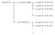
従来の電子カメラ等による撮影動作によって生成された画像データが所定の記録媒体に記録される場合において、従来の記録媒体におけるディレクトリ構造は、例えば次のように設定されるものがある。
【0005】
図12に示すように記録媒体における記録領域の[ROOT]の下層領域に所定のディレクトリ[100OLYM]が作成されている。そして、この所定のディレクトリ[100OLYM]の下層領域に各画像データに対応する個々のデータファイルが順次記録されるようになっている。
【0006】
この場合において、それぞれのデータファイルに付するファイル名は、例えば図12に示すように[im2010001]・[im2010002]……[im2010099]なる。この例では、ファイル名の先頭に共通符号を付し、これに続けて電子カメラ等の内部に設けられる時計機能等からのデータを利用して、日付情報等及び撮影(取得)順に付される連番号等を割り振るようにしている。
【0007】
つまり、上述の例では、先頭の二文字[im]は共通符号であり、これに続く次の四文字[2010]は、例えば2000年10月を表わす略号であり、最終の三つの数字がファイル番号となる。したがって、このファイル番号は[001]〜[999]まで連番で付されるわけである。
【0008】
そして、この場合には、所定のディレクトリ下に記録されたデータファイルのファイル番号のうち最も大きな番号を有するものを最新の画像データに対応するデータファイルとして識別するようにしている。
【0009】
ところで、従来の電子カメラ等においては、これによって記録される画像データのデータ構造を、所定の規格によって構成するようにし、各種の電子カメラにおいて、この所定の同一規格を採用することで、異なる電子カメラであっても同じデータ構造を有するデータファイルが生成されるようにしている。この場合には、例えば同じタイプの記録媒体を使用する電子カメラ同士においては、同一の記録媒体を相互の電子カメラによって共に使用することができるようになる。
【0010】
一方、従来の電子カメラによって画像データが記録された所定の記録媒体を装着し、当該記録媒体に記録された画像データを読み出して、この読み出した画像データによって表わされる画像を印刷用紙等に印刷出力する画像印刷装置については、例えば特開平10−107984号公報等によって種々の提案がなされ、また一般的に実用化されている。
【0011】
上記特開平10−107984号公報によって開示されている画像印刷装置は、予め設定されているファイル読み出し条件に従って設定された記録媒体から自動的に画像データを読み出すように制御し、この読み出された画像データに基づいて印刷動作を実行するというものである。
【0012】
【発明が解決しようとする課題】
ところが、従来の電子カメラ等においては、データファイルを記録するべきディレクトリ名が個々の電子カメラ等によってそれぞれ異なる設定となっている場合がある。このような場合において、複数の電子カメラ等において同一の記録媒体を共用した場合には、その記録媒体の記録領域には、各電子カメラ等のそれぞれに対応するディレクトリが作成され、各ディレクトリ下にそれぞれデータファイルが記録されることになる。したがって、複数作成されたディレクトリ下に存在する複数のデータファイルのうちいずれのデータファイルが最新のものであるかを識別することができないという問題点がある。
【0013】
また、日付情報を利用してデータファイルのファイル名を設定するようにしているものでは、電子カメラ等の内部時計機能の調整を確実に設定しておかなければ、正確な日付情報を得ることができないのは自明である。したがって、この場合にも、最新の画像データを確実に識別することが困難になってしまう場合がある得るという問題点がある。
【0014】
一方、上記特開平10−107984号公報によって開示されている手段では、画像データを読み出すためのファイル読み出し条件を予め設定しておく必要があり、煩雑な操作が要求されるものと考えられる。
【0015】
本発明は、上述した点に鑑みてなされたものであって、その目的とするところは、撮影動作により取得した画像データを保存する所定のディレクトリと、常に最新の画像データを一時的に保存する所定のディレクトリとを記録媒体の内部に構成するようにした電子カメラと、電子カメラに用いられる同一の記録媒体を装着し、当該記録媒体に記録された大量の画像データのうち最新の画像データを特別な操作をすることなく読み込み、これに基づく画像を所定の表示装置に表示させ得ると共に、この画像データにより表わされる画像を印刷出力することを容易に実行できる画像印刷装置を提供することにある。
【0016】
【課題を解決するための手段】
上記目的を達成するために、第1の発明による電子カメラは、被写体像を光電変換して電子的な画像データを得るための撮像手段と、上記撮像手段により得られた画像データを保存する保存フォルダと、この保存フォルダに保存する前に一時的に上記画像データを保存する最新フォルダとを有する記録媒体を着脱自在にする装着手段と、上記撮像手段により得られた画像データを上記装着手段に装着された記録媒体内の最新フォルダに記録するための記録手段と、上記装着手段に装着された記録媒体内の最新フォルダに保存されている画像データを保存フォルダへと転送するための転送手段とを備えてなることを特徴とする。
【0017】
これによれば、複数種類の異なる電子カメラにおいて使用された単一の記録媒体に記録される画像データに基づいて所望の画像を画像印刷装置を用いて印刷する場合にも、最新の画像(最も最近取得した画像データによる画像)を容易にかつ素早く検索し、かつ表示させることができると同時に、所望の画像の印刷をも容易に行なうことができる。
【0018】
また、第2の発明は、上記第1の発明による電子カメラにおいて、上記転送手段は、電源のオン操作に応じて上記装着手段に装着された記録媒体内の最新フォルダに保存されている画像データを保存フォルダに転送することを特徴とする。
【0019】
そして、第3の発明は、上記第1の発明による電子カメラにおいて、上記撮像手段により撮影を行なう撮影モードと上記記録媒体から画像データを読み出して再生を行なう再生モードとを有し、これらのモードを選択的に切り換えるためのモード切換手段を備え、上記転送手段は、上記モード切換手段による撮影モードへの切り換え操作に応じて上記装着手段に装着された記録媒体内の最新フォルダに保存されている画像データを保存フォルダに転送することを特徴とする。
【0020】
上記第2の発明及び上記第3の発明によれば、最新フォルダから保存フォルダへと画像データを転送するための特別な操作を必要とせずに、自動的にデータ転送が行なわれるようにしたことから、使用者は煩わしい操作を行なうことなく良好な使用感を得ることができる。
【0021】
第4の発明は、第1の発明・第2の発明・第3の発明のうちのいずれかひとつに記載の電子カメラにおいて、上記記録媒体は、画像データが記録される画像データ領域と、この画像データ領域に記録される画像データに関する属性情報が記録される媒体情報領域とを有してなり、最新フォルダから保存フォルダへ転送させたくない画像データに対し、保存フォルダへの転送禁止を示す転送禁止情報を属性情報に付加して当該画像データを転送禁止画像データに設定するための設定手段を備えたことを特徴とする。
【0022】
第5の発明による画像印刷装置は、上記第1の発明の電子カメラによって撮影された画像データを保存した上記記録媒体が着脱自在に配設される画像印刷装置であって、上記記録媒体に保存された画像データに基づく画像を記録紙上に印刷するための印刷手段と、最新フォルダの画像を表示する旨の操作がなされたときには、当該装置に装着された上記記録媒体内の最新フォルダに保存されている画像データを読み出して表示用の画像データを生成するための生成手段と、この生成手段により生成された表示用の画像データを上記表示装置に出力するための出力手段とを備えたことを特徴とする。
【0023】
これによれば、複数の電子カメラにおいて使用された単一の記録媒体に記録された画像データに基づいて所望の画像を画像印刷装置を用いて印刷する場合にも、最新の画像(最も最近取得した画像データによる画像)を容易にかつ素早く表示させ、かつすぐに所望の画像の印刷を行なうことができる。
【0024】
第6の発明は、第5の発明による画像印刷装置において、上記生成手段は、最新フォルダに保存されている複数の画像データを読み出してインデックス表示用の画像データを生成し得るように構成されていることを特徴とする。
【0025】
これによれば、最新フォルダの画像の一覧表示(インデックス表示)を容易に行なうことができるので、印刷したい所望の画像を容易にかつ素早く検索することができる。
【0026】
【発明の実施の形態】
以下、図示の実施の形態によって本発明を説明する。
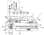
図1・図2は、本発明の一実施形態における画像印刷装置を示し、図1は当該画像印刷装置を正面側から見た際の外観斜視図、図2は当該画像印刷装置の内部構成を示すブロック構成図である。
【0027】
本実施形態の画像印刷装置は、例えば三色のインクリボン(Y(イエロー)・M(マゼンタ)・C(シアン))を一枚の印刷記録紙(以下、印刷用紙という)に対して面順次に重ねて印刷するようにしたいわゆる熱昇華型の画像印刷装置である。
【0028】
本画像印刷装置1は、各種の構成部材を内部に有すると共に、図1に示すように各種の操作部材等を外装に備えて構成される本体部11と、この本体部11の前面側から当該本体部11の内部に向けた方向に挿脱自在に設けられ、本画像印刷装置1によって所望の画像を印刷記録するための印刷用紙等を複数収納する用紙収納部材12等によって構成されている。
【0029】
本体部11の前面には、上述の用紙収納部材12を挿入する開口11aが設けられているほか、本画像印刷装置1によって印刷すべき画像を表わす画像データを記録した、例えばカード形状の半導体記録媒体や円盤形状の磁気記録媒体等の記録媒体3を着脱自在に配設する記録媒体装着用開口13や、記録媒体3又は外部の画像再生装置などから当該画像印刷装置1へと入力される画像データ又はビデオ信号等に対して所定の処理等を施した画像信号を出力する出力手段であるビデオ出力端子25等がそれぞれ所定の位置に配設されている。
【0030】
本体部11の上面側には、本画像印刷装置1により所望の印刷動作を行なわしめるための各種の操作部材からなる操作部15が配設されている。この操作部15としては、例えば十字キー15aや予約/決定キー15b・印刷キー15c・分割キー15d・拡大キー15e・縮小キー15f・入力モード選択キー15g等がある。
【0031】
十字キー15aは、一つの操作部材を四方向に操作し得るように構成された操作部材であり、本画像印刷装置1によって実行し得る各種の動作等を選択する場合、所望の画像データを生成するために表示画面の表示中の画像の移動や画像データの予約選択を行なう際のカーソル移動等の操作時に用いられる移動操作手段である。
【0032】
予約/決定キー15bは、上述の十字キー15aにより選択した所望の動作等を予約又は決定する際に操作される操作部材である。
【0033】
印刷キー15cは、実際の印刷動作の実行を開始させる際に操作する操作部材である。
【0034】
分割キー15dは、印刷動作を行なう際の印刷形態の選択、即ち分割印刷モードか又は標準モードである一画像印刷モードかの所望の印刷形態を選択するために操作される。
【0035】
拡大キー15e及び縮小キー15fは、印刷対象となる画像データに対して所定の信号処理を施す際に操作される操作部材であって、このうち拡大キー15eは、例えば画像の拡大処理を実行する際に操作し、縮小キー15fは、例えば画像の縮小処理を実行する際に操作するものである。
【0036】
入力モード選択キー15gは、摺動式の操作部材からなり所望の入力モードを選択し切り換えるための操作部材である。つまり、この入力モード選択キー15gは、図1の矢印X方向に摺動自在に配設されていて、当該入力モード選択キー15gを摺動させて所定の位置に配置することによって所望の入力モードを選択するための操作部材である。
【0037】
入力モード選択キー15gによって切り換えることのできる入力モードには、各種の形態が考えられるが、本実施形態においては、例えば標準(ノーマル)モード・全画像モード・カメラ予約モード・最新画像モードの四つの形態を選択し切り換えることができるようにしている。
【0038】
ここで、標準(ノーマル)モードは、記録媒体に記録済みの画像データによって表示される画像を本画像印刷装置に接続される所定の表示装置(図示せず)に表示させ、所望の画像データを任意に選択し、この選択した画像データを印刷動作の対象とするための入力モードである。
【0039】
全画像モードは、記録媒体に記録されている全ての画像データを印刷動作の対象とする入力モードである。
【0040】
カメラ予約モードは、当該電子カメラによって印刷予約がなされている画像データ、即ち記録媒体に記録済みの複数の画像データのうち印刷を所望する画像データであって当該電子カメラによって予め所定の識別信号等が付加された画像データを印刷動作の対象とするための入力モードである。
【0041】
最新画像モードは、記録媒体3の最新フォルダ([LATEST]フォルダ;詳細は後述する)下の領域に記録されている一群の画像データを印刷動作の対象とする入力モードである。
【0042】
また、本画像印刷装置1には、当該画像印刷装置1の動作時における各種の状態等を表示する表示部16が、正面から上面にかけて外縁部の所定の位置に配設されている。この表示部16には、例えば複数の発光ダイオード(LED)等が用いられており、その点灯又は点滅によって各種の表示を行ない得るようになっている。この表示部16による表示としては、例えば、
・主電源の通電状態を表示する電源状態表示、
・印刷動作が実行中であることを表示する印刷実行表示、
・設定されている印刷モードの状態等を表示する印刷モード表示、
・印刷用紙又は印刷用インクリボン等の供給不足等になったことを表示する用紙/リボン切れ表示、
・各種のエラーの発生を警告するエラー警告表示、
等がある。
【0043】
次に、本実施形態の画像印刷装置1の内部構成について、以下に説明する。なお、図2において示す点線は制御信号線を、実線はデータ信号線をそれぞれ示している。
【0044】
本実施形態の画像印刷装置1は、所望の画像を印刷するのに際して所定の画像データを外部より取り込む必要があるが、この場合に用いられる信号入力系統は、次に示す三系統の画像信号入力手段が具備されている。即ち、
・ビデオテープレコーダ等の外部の画像再生装置(図示せず)等と本画像印刷装置1とを電気的に接続し、当該画像再生装置から出力されるビデオ信号を入力する接続端子であり、例えば一般的なビデオ映像信号ピン(RCA Pin)14aやいわゆるS端子(MiniDin 4P)14b等のビデオ入力端子14、
・電子カメラ等において画像データ等を記録するための記録媒体3(図2では図示せず。図1参照)を着脱自在に配設し、この記録媒体3が装着されたときには、当該記録媒体3と本画像印刷装置1とを電気的に接続する記録媒体接続手段であるカード接続部26、
・外部の小型コンピュータ等の画像処理装置等(図示せず)と本画像印刷装置1とを電気的に接続する所定の接続端子であるセントロニクス接続部34(パラレル接続手段)やUSB(Universal Serial Bus)接続部35(シリアル接続手段)、
の三系統の画像信号入力手段である。
【0045】
そして、これらのうちカード接続部26には、当該カード接続部26に装着される記録媒体3に記録されている画像データの読み込み等を行なうカードインターフェース(以下、カードI/Fと略記する)27が電気的に接続されている。
【0046】
また、セントロニクス接続部34及びUSB接続部35には、これらを介して入力される画像データを受けるプリンタインターフェース(以下、プリンタI/Fと略記する)36が電気的に接続されている。
【0047】
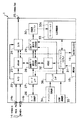
また、本画像印刷装置1は、ビデオ入力端子14を介して本画像印刷装置1の内部に取り込まれる画像信号(アナログ信号)をデジタル信号に変換するA/D変換回路(図2では単にA/Dと略記している)22と、このA/D変換回路22によって変換された静止画像を表わすデジタル画像信号を一時的に記憶するビデオラム(VRAM)23と、このVRAM23からの出力信号又はA/D変換回路22からの出力信号等を受けて、この出力信号(画像データ)により表わされる画像を所定の画像表示装置(図示せず)に表示するのに最適な形態の画像信号(アナログ信号)へと変換するD/A変換回路(図2では単にD/Aと略記している)24と、このD/A変換回路24によって生成された画像信号が出力されるビデオ出力端子(Video Out)25と、上述のカード接続部26に接続された記録媒体3(図示せず)から当該カード接続部26及びカードI/F27を介して本画像印刷装置1に入力される画像データを一時的に記憶する画像データ保存用DRAM28と、本画像印刷装置1の全体を制御する制御手段であって、例えばCPU等からなるワンチップマイコン31と、カード接続部26に装着された記録媒体3から画像データ保存用DRAM28へと読み込まれた画像データに対してファイル展開処理等、各種の信号処理等を行なうために本画像印刷装置専用に作成された集積回路であるASIC(Application Specific Integrated Circuit;エーシック:以下、単にASICという)32と、画像データ保存用DRAM28に一時的に記憶され、所定の信号処理が施された後に出力される印刷用の画像データ、またはセントロニクス接続部34及びUSB接続部35からプリンタI/F36を介して本画像印刷装置1へと入力される画像データ等を受けて、これを一時的に記憶する印刷データ保存用DRAM29と、この印刷データ保存用DRAM29から順次出力される一ライン毎のデータを受けて、これを印刷手段、即ち印刷動作を実行するための印刷機構部33の熱転写印字ヘッド(サーマルヘッド)33aへと出力する印刷用バッファー30と、本画像印刷装置1を動作させるために各種の指示信号を発生させる複数の操作スイッチ及び回路等からなる操作部15と、本画像印刷装置1の状態を表示する複数のLED等からなる表示部16等の各種の構成部材を具備して構成されている。
【0048】
一方、本画像印刷装置1を用いて画像の印刷出力を行なう際に当該画像印刷装置1に入力する画像データを生成(取得)するための電子カメラ2の構成について、以下に説明する。図3は、本発明の一実施形態における電子カメラの内部構成を示すブロック構成図である。
【0049】
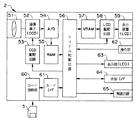
本実施形態の電子カメラ2は、図3に示すように被写体光束を集光し被写体像を結像する撮影レンズ系51と、この撮影レンズ系51によって結像される被写体像を電気的な信号に光電変換するCCD等の撮像手段である撮像素子52と、この撮像素子52を駆動制御するCCD駆動回路53と、撮像素子52によって光電変換された画像信号(アナログ信号)をデジタル信号に変換するA/D変換回路(図3では単にA/Dと略記している)54と、このA/D変換回路54によってデジタル信号化された画像信号を一時的に記憶する不揮発性メモリ又はバッファメモリ等からなるRAM55と、本電子カメラ2の全体を電気的に制御するCPU等からなるシステム制御回路56と、RAM55に一時的に記憶されたデジタル画像信号を液晶ディスプレイ(LCD)等からなる表示装置59等の表示画面上に表示するのに最適な形態のビデオ信号等に変換する信号処理等を施すビデオラム(VRAM)57と、このVRAM57により変換されたビデオ信号等を受けて画像として表示するための画像表示手段である表示装置59と、この表示装置59を駆動制御するLCD駆動回路58と、RAM23に一時的に記憶されているデジタル画像信号を所定の形態の画像データファイルとして記録する媒体であって、例えば不揮発性メモリや磁気記録媒体等からなる記録媒体3を本電子カメラ2に対して着脱自在に配設するための装着手段であるカード接続部60と、記録媒体3と本電子カメラ2とを電気的に接続するカードインターフェース(カードI/F)61と、システム制御回路56に対して各種の指示信号を入力する複数の入力スイッチ等からなる操作部62と、本電子カメラ2の状態を表示するために設けられ複数の発光ダイオード(LED)等によって構成される表示部63と、本電子カメラ2と画像印刷装置1等の各種の外部機器とを電気的に接続する外部インターフェース(I/F)64と、本電子カメラ2の各種の電気回路等に対して電力の供給を行なう乾電池等の主電源を含む電源回路65等によって構成されている。
【0050】
表示装置59は、本電子カメラ2が撮影モード(又はカメラモードともいう)で動作しているときには、撮像素子52によって生成される画像信号を受けて、これを画像として表示させ得るように構成されているものである。したがって、撮影時における所望の撮影範囲や被写体像の確認等を行なうファインダー手段の役目をする一方、本電子カメラ2が再生モードにあるときには、記録媒体3等に記録済みの画像データを画像として表示する画像表示手段の役目をしている。
【0051】
このように構成された本電子カメラ2による撮影動作が実行されると、所定の形態の画像データファイルが取得され記録媒体3に記録されることになる。この記録媒体3の内部構造を図4の概念図に基づいて、以下に説明する。
図4は、記憶容量が例えば16MB(メガバイト)に設定された記録媒体3を例に挙げて示している。
【0052】
本電子カメラ2によって作成され、画像データ及びこれに付随する各種の情報等(属性情報という)からなる画像データファイルは、記録媒体3の内部の所定の領域に記録されることとなる。この記録媒体3は、図4に示すように複数のセクタと呼ばれる領域に分かれている。
【0053】
記録媒体3の先頭の領域であるセクタ、即ち先頭のアドレス値(000000)から始まる所定範囲の領域(セクタ)には、媒体情報領域である[カード情報領域]Aが設けられている。この[カード情報領域]Aには、当該記録媒体3の[ディレクトリ情報]や記録媒体3に記録されている画像データファイルの[ファイル情報]及び[ファイルアドレス情報]等の各種の情報、即ち画像データに関する属性情報が記録される。なお、後述する[移動禁止情報(転送禁止情報)]等は、この[ファイル情報]、即ち属性情報に付加されて記録されることになる。
【0054】
また、先頭のセクタA以外の他の領域、即ち[カード情報領域]Aのセクタの直後の領域から最後のアドレス値(FFFFFF)までの範囲の領域は、[画像データ領域]Bとされており、この[画像データ領域]Bには、上述の[カード情報領域]Aから参照されるアドレス値に対応する位置にそれぞれ画像データファイルが記録されるようになっている。
【0055】
次に、本実施形態の電子カメラ2及び画像印刷装置1において使用される記録媒体3のディレクトリ構造について、以下に説明する。
【0056】
記録媒体3のディレクトリ構造は、図5・図6・図7に示すように[ROOT]ディレクトリの下層領域に二つのフォルダ(又はディレクトリともいう。この例では[100OLYM]ディレクトリと[LATEST]ディレクトリ)によって構成されている。この二つのディレクトリのうち[100OLYM]ディレクトリは、画像データファイルを保存するためのディレクトリ(保存フォルダという)であり、[LATEST]ディレクトリは、[100OLYM]ディレクトリに保存する以前に画像データファイルを一時的に保存するためのディレクトリ(最新フォルダという)である。
【0057】
つまり、本電子カメラ2によって撮影動作が実行されて所定の形態の画像データファイルが記録媒体3に記録される際の作用を簡単に説明すると、以下のようになる。
【0058】
本電子カメラ2を用いて撮影動作を行なうためには、まず記録媒体3を電子カメラ2のカード接続部60に装着し、当該電子カメラ2の主電源をオン状態にする。なお、説明を簡略化するために電子カメラ2に装着される記録媒体3は初期状態、即ち内部に画像データファイルが記録されていない状態にあるものとする。
【0059】
この場合において、本電子カメラ2を用いて撮影動作を開始すると、この撮影動作によって取得された画像データファイルは、図5に示すように記録媒体3の[LATEST]ディレクトリの下層領域に順次記録されることになる。このとき、[100OLYM]ディレクトリの下層領域は、画像データファイルが存在しない空白(blank)の状態にある。そして、一連の撮影動作を終了して電子カメラ2の主電源をオフ状態にする。図5に示す例では、今回の一連の撮影動作によって取得された10画像分の画像データファイルが記録媒体3の[LATEST]ディレクトリに保存されている状態が示されている。
【0060】
この状態において、次の撮影動作を実行するためには、再度電子カメラ2の主電源をオン状態にする。すると、前回の撮影動作によって取得され記録媒体3の[LATEST]ディレクトリの下層領域に記録されている各画像データファイル(10画像分)が、当該[LATEST]ディレクトリの下層領域から[100OLYM]ディレクトリの下層領域へと移動(又は転送)されることになる。この移動処理(又は転送処理)は、記録媒体3の[カード情報領域]Aの[ディレクトリ情報]や[ファイル情報]等を書き換えることにより行なわれる。
【0061】
これにより、図6に示すように記録媒体3の[LATEST]ディレクトリの下層領域は、画像データファイルが存在しない空白(blank)の状態になると同時に、[100OLYM]ディレクトリの下層領域には、前回の撮影動作で取得した上述の10画像分の画像データファイルが記録されている状態になる。
【0062】
そして、この状態において撮影動作を開始すると、今回の撮影動作によって取得され新規に記録される画像データファイルは、図7に示すように[LATEST]ディレクトリの下層領域に順次記録されることになる。
【0063】
このとき、[LATEST]ディレクトリの下層領域に新規に記録される画像データファイルのファイル名は、前回の撮影動作により取得され記録済みの画像データファイル、即ち[100OLYM]ディレクトリの下層領域に記録されている複数(10画像分)の画像データファイルのうち最大番号を有するファイル名に連続する新規の番号が最新ファイル名に割り振られる。図7に示す例では、前回の撮影動作による記録済み画像データファイルの最大番号を有するファイル名は、[im2010010]であるから、今回の撮影動作によって[LATEST]ディレクトリの下層領域に新規に記録される最新の画像データファイルのファイル名は、[im2010011]から降順に割り振られることになる。
【0064】
そして、本電子カメラ2における撮影動作時に取得される画像データファイルは、上述したディレクトリ構造を有する記録媒体3に対して所定の形態で記録される。この記録媒体3を本実施形態の画像印刷装置1に装着した後、所定の操作を実行することによって、所望の画像データを当該画像印刷装置1へと転送し、当該所望の画像を画像印刷装置1に接続される画像表示装置に表示させたり、同画像の印刷出力物を得ることができるようになっている。
【0065】
次に、本実施形態の電子カメラ2及び画像印刷装置1の作用を以下に説明する。
まず、本実施形態の電子カメラ2による撮影動作時及び再生動作時の作用を説明する。
【0066】
本実施形態の電子カメラ2は、各種の動作モードによって動作させることができるようになっている。例えば、所望の画像データを取得しこれを所定の形態の画像データファイルとして記録媒体3に記録するカメラモード(撮影モード)や、この記録媒体3に記録済みの画像データファイルを再生する再生モード等の各種の動作モードである。以下の説明においては、本電子カメラ2の動作モードとして、カメラモード(撮影モード)と再生モードとの二つの動作モードについてのみ説明するものとする。
【0067】
初めに本電子カメラ2の動作モードのうちのカメラモード(撮影モード)で動作する際の動作の流れを図8のフローチャートを用いて、以下に説明する。
【0068】
まず、本電子カメラ2のカード接続部60に所定の記録媒体3を装着した状態で、例えば操作部62のうちの電源のオン又はオフ状態を切り換える所定の操作部材(電源切換部材)を操作する。すると、図8のステップS1において、システム制御回路56は、電源回路65をオン状態とするための所定のパワーオン処理を実行する。
【0069】
即ち、電源切換部材が電源オンとなる方向に操作されたことを受けて、当該操作部材に連動するスイッチが作動し、これにより電源状態をオン状態とするための所定の指示信号(電源オン信号という)が生じる。すると、同信号は、システム制御回路56を介して電源回路65へと伝達される。これによりシステム制御回路56は、当該電源回路65をオン状態とする所定の処理を実行する。そして、電源回路65がオン状態になると、当該電子カメラ2の各電気回路は、所定の主電源(図示せず)から所定量の電力供給を受けることになる。これらの一連の処理をパワーオン処理という。
【0070】
こうして電源回路65がオン状態に移行すると、次にシステム制御回路56は、ステップS2において本電子カメラ2の動作モードがカメラモード(撮影モード)又は再生モードのいずれのモードに設定されているかの判断を行なう。この場合における動作モードの確認は、例えば操作部62のうち動作モードを切り換えるための所定の操作部材(操作部62に含まれる;モード切換手段)からの所定の指示信号(動作モード切換信号という)を確認することにより実行される。
【0071】
ここで、動作モードがカメラモード(撮影モード)に設定されていることが確認された場合には、次のステップS3の処理に進み、所定のカメラモード処理が実行される。一方、動作モードが再生モードに設定されていることが確認された場合には、ステップS11の処理へと進み、再生モード処理(詳細は後述する。図10参照)が実行される。
【0072】
カメラモードに設定されていることが確認されると、次のステップS3において、システム制御回路56は、図4に示す[カード情報領域]Aを参照し、記録媒体3の[LATEST]ディレクトリの下層領域がカラ(空)の状態にあるか否か、即ち記録媒体3の[LATEST]ディレクトリの下層領域に既に画像データファイルが記録されている状態にあるか否かの確認を行なう。ここで、記録媒体3の[LATEST]ディレクトリの下層領域がカラ(空)の状態であることが確認されると、ステップS5の処理に進む。また、当該記録媒体3の[LATEST]ディレクトリの下層領域に画像データファイルが既に記録されている状態にある場合、即ち前回の撮影動作によって記録された画像データファイルが存在する場合には、ステップS4の処理に進む。
【0073】
ステップS4において、システム制御回路56は、記録媒体3の[LATEST]ディレクトリの下層領域に記録されている画像データファイルを[100OLYM]ディレクトリの下層領域に移動させるための移動処理(詳細は後述する。図9参照)を実行する。ここで、システム制御回路56は、記録媒体内における所定の画像データファイルの転送手段の役目をしている。このファイル移動処理によって、本電子カメラ2に装着されている記録媒体3の[LATEST]ディレクトリの下層領域は、カラ(空)の状態になる。
【0074】
次いでステップS5において、システム制御回路56は、撮影モードによって撮影動作を実行するのに先立って本電子カメラ2の所定の各部材の初期設定、例えば撮影レンズの初期位置設定等の初期処理を実行する。そして、次のステップS6の処理に進む。
【0075】
ステップS6において、システム制御回路56は、操作部62のうち撮影動作を開始するレリーズキー(図示せず)が押されたか否かの確認を行なう。ここでシステム制御回路56は、レリーズキーが押されることによって生じる指示信号、即ち撮影動作の開始を指示する所定の指示信号(レリーズ指示信号という)の有無を確認する。
【0076】
この場合においてシステム制御回路56がレリーズ指示信号を確認し、レリーズキーが押されているものと判断された場合には、次のステップS7の処理に進む。一方、レリーズ指示信号が所定の時間の間に発生しておらず、よってレリーズキーが押されていないものと判断された場合には、ステップS12の処理に進む。
【0077】
レリーズキーの押圧動作が確認されてステップS7の処理に進むと、このステップS7において、システム制御回路56は、撮影動作に関連する所定の構成部材を制御して所定の撮影処理を実行する。その後、ステップS8の処理に進む。なお、ここで実行される撮影処理は、従来の一般的な電子カメラ等によって行なわれる一連の撮影処理であり、例えば画像データの生成処理やデータ圧縮処理等である。この撮影処理自体については、本発明に直接関連するものではないので、その処理の詳細な説明は省略する。
【0078】
次いで、ステップS8において、システム制御回路56は、上述のステップS7の撮影処理によって取得し生成した所定の形態の画像データファイルを、カードI/F61及びカード接続部60を介して当該カード接続部60に装着されている記録媒体3の[LATEST]ディレクトリの下層領域に保存(記録)する。したがって、システム制御回路56は、撮像素子52により生成され所得された画像データに対して信号処理を施して所定の形態の画像データファイルを作成すると共に、これを記録媒体3の[LATEST]ディレクトリ(最新フォルダ)へと記録するための記録手段の役目をしている。そして、次のステップS9の処理に進む。
【0079】
ステップS9において、システム制御回路56は、電源回路65を監視して当該電源回路65がオフ状態にされたか否かの確認を行なう。つまり、操作部62のうちの電源のオン又はオフ状態を切り換える所定の操作部材(電源切換部材)が操作され、これに連動するスイッチによって電源をオフ状態とするための所定の指示信号(電源オフ信号という)が生じたか否かの判断を行なう。ここで、電源オフ信号が生じていると判断された場合には、次のステップS10の処理に進み、このステップS10において、パワーオフ処理が実行された後、一連の撮影動作のシーケンスを終了する(エンド).
上述のパワーオフ処理は、次のような一般的な処理である。即ち所定の操作部材から生じた電源オフ信号は、システム制御回路56を介して電源回路65へと伝達される。これを受けて当該電源回路65はオフ状態に移行する。これによって電源回路65がオフ状態となり、当該電子カメラ2における各電気回路への主電源からの電力供給は切断される。
【0080】
上述のステップS9において、システム制御回路56は、電源切換部材からの指示信号が所定の時間の間に発生しておらず、電源オフ信号が生じていないものと判断した場合には、上述のステップS6の処理に戻り、以降の処理を繰り返す。
【0081】
一方、上述のステップS6において、レリーズキーの押圧動作が確認されずにステップS12の処理に進むと、このステップS12において、システム制御回路56は、操作部62における複数の設定キー(詳細は図示せず)のうちのいずれかの設定キーが操作されたか否かの確認を行なう。ここで、操作部62のうちのいずれかの設定キーが操作されたることにより生じる所定の指示信号が確認された場合には、操作部62のいずれかの設定キーが操作されたものと判断されて、次のステップS13の処理に進む。
【0082】
このステップS13において、システム制御回路56は、上述のステップS12において操作された所定の設定キーに応じた所定の設定変更処理を実行する。そして、上述のステップS9の処理に進み、以降の処理を繰り返す。
【0083】
このようにして、本電子カメラ2によって撮影動作が実行され、複数の画像データファイルが記録媒体3に記録される場合には、記録媒体3の内部においては、最新の画像データファイルが[LATEST]ディレクトリの下層領域に常に記録されることになる。そして、電源回路65がオン状態からオフ状態へと切り換わる際には、[LATEST]ディレクトリの下層領域に画像データファイルが記録されていると、それらの画像データファイルは、[LATEST]ディレクトリ以外の所定のディレクトリ(本実施形態においては[100OLYM])へと自動的に移動(転送)されるようになっている。
【0084】
次に、本電子カメラ2の撮影動作がなされるときに実行される画像データファイルの移動処理について図9のフローチャートに基づき、以下に説明する。このファイル移動処理は、上述の図8に示すステップS4の処理である。
【0085】
上述したように図8のステップS3において、システム制御回路56は、記録媒体3の[LATEST]ディレクトリの下層領域がカラ(空)の状態にないものと判断した場合に、図8のステップS4の処理、即ち図9に示すファイル移動処理に進む。
【0086】
このファイル移動処理に進むと、まず図9のステップS21において、システム制御回路56は、図4に示す[カード情報領域]Aを参照し、[LATEST]ディレクトリの[ファイル情報]を取得し、次のステップS22の処理に進む。
【0087】
ステップS22において、システム制御回路56は、上述のステップS21の処理で取得した個々の画像データファイルの[ファイル情報]のうち[移動禁止情報(転送禁止情報)]の有無を確認する。この[移動禁止情報(転送禁止情報)]は、例えば電子カメラ2の操作者が所定の操作部材(操作部62に含まれる;設定手段)による設定操作を任意に行なうことにより所望の画像データファイルに対して所定の属性情報を付加することで、その画像データファイルの削除や移動等を一時的に禁止するようにするために付加される属性情報である。これは、電子カメラ2の操作者が、例えば撮影動作の直後等に印刷を所望する特定の画像データファイルに対して、この[移動禁止情報(転送禁止情報)]を属性情報に付加しておくことで、その特定の画像データファイルを[LATEST]ディレクトリに残しておくことができる。したがって、この特定の画像データファイルについては、検索の手間をかけることなく即座に再生動作や印刷動作等を実行することができるのである。
【0088】
このステップS22において、[LATEST]ディレクトリにある画像データファイルに[移動禁止情報(転送禁止情報)]が属性情報に付加されていないことがシステム制御回路56によって確認されると、当該システム制御回路56は、カードI/F61を介して記録媒体3の[カード情報領域]Aの[ファイル情報]の書き換え処理を行なう。つまり、その画像データファイルについての[ファイル情報]を[LATEST]ディレクトリに属する旨の情報から、[100OLYM]ディレクトリに属する旨の情報へと書き換える。これにより、画像データファイルは、[LATEST]ディレクトリから[100OLYM]ディレクトリへと移動(転送)されたことになる。その後、ステップS24の処理に進む。
【0089】
一方、上述のステップS22において、[LATEST]ディレクトリにある画像データファイルに[移動禁止情報(転送禁止情報)]が属性情報に付加されていることが確認された場合には、実際のファイル移動処理を実行せずにステップS24の処理に進む。
【0090】
ステップS24において、システム制御回路56は、ファイル終了を示す旨の情報を確認し、ファイル終了情報が確認されるまで、ステップS21以降の処理を繰り返す。つまり、[LATEST]ディレクトリ内に記録されている画像データファイルの全てについて、[移動禁止情報(転送禁止情報)]の確認とファイル移動処理を繰り返す。
【0091】
次に、本電子カメラ2の動作モードのうち再生モードで動作する際の動作の流れを図10のフローチャートを用いて、以下に説明する。
まず、本電子カメラ2のカード接続部60に所定の記録媒体3を装着した状態で、例えば操作部62のうちの電源のオン又はオフ状態を切り換える所定の操作部材(電源切換部材)を操作する。すると、図10のステップS31において、システム制御回路56は、電源回路65をオン状態とするための所定のパワーオン処理を実行する。このステップS31の処理は、上述の図8のステップS1のパワーオン処理と同様である。
【0092】
電源回路65がオン状態に移行すると、次にシステム制御回路56は、ステップS32において本電子カメラ2の動作モードがカメラモード又は再生モードのいずれのモードに設定されているかの判断を行なう(図8のステップS2と同様)。
【0093】
ここで、動作モードが再生モードに設定されていることが確認された場合には、次のステップS33の処理に進み、所定の再生モード処理が実行される。一方、動作モードがカメラモードに設定されていることが確認された場合には、ステップS30の処理へと進み、上述の図8で説明したカメラモード処理が実行される。
【0094】
再生モードに設定されていることが確認されると、次のステップS33において、システム制御回路56は、図4に示す[カード情報領域]Aを参照し、記録媒体3の[LATEST]ディレクトリの下層領域がカラ(空)の状態にあるか否かの確認を行なう(図8のステップS3と同様)。
【0095】
ここで、記録媒体3の[LATEST]ディレクトリの下層領域がカラ(空)の状態であることが確認されると、ステップS39の処理に進む。また、当該記録媒体3の[LATEST]ディレクトリの下層領域に画像データファイルが既に記録されている状態にある場合、即ち前回の撮影動作によって記録された画像データファイルが存在する場合には、ステップS34の処理に進む。
【0096】
ステップS34において、システム制御回路56は、記録媒体3の[LATEST]ディレクトリの下層領域に記録されている画像データファイルのうち本電子カメラ2の表示装置59を用いて再生表示を行なうべき画像に対応する画像データファイルを選択し、これを表示装置59の表示画面に画像として表示させる。このとき選択される画像データファイルは、[ファイル情報]のうちファイル名に関する情報等が参照される。ここで、まず初めに選択される画像データファイルは、例えば[LATEST]ディレクトリの下層領域に記録されている画像データファイルのうち最大のファイル番号を有する画像データファイルである。
【0097】
一方、上述のステップS33において、記録媒体3の[LATEST]ディレクトリの下層領域がカラ(空)の状態であることが確認された場合にステップS39の処理に進むと、このステップS39において、システム制御回路56は、上述のステップS33の処理と同様の手段により[100OLYM]ディレクトリの下層領域がカラ(空)の状態にあるか否かの確認を行なう。ここで、[100OLYM]ディレクトリの下層領域もカラ(空)の状態であることが確認されると、ステップS46の処理に進む。この場合には、当該記録媒体3には一つの画像データファイルも存在していないことになる。したがって、ステップS46において、システム制御回路56は、LCD駆動回路58を制御して表示装置59に画像データファイルが存在しない旨の表示を行なう。その後ステップS47の処理に進む。
【0098】
ステップS47において、システム制御回路56は、電源回路65を監視して当該電源回路65がオフ状態にされたか否かの確認を行なう。つまり、操作部62のうちの電源切換部が操作された(押された)か否かの確認を行なう。この処理は上述の図8のステップS9の処理と同様である。
【0099】
そして、当該電源切換部材が操作された、即ち電源をオフ状態とするための操作(パワーオフ操作)がなされたことが確認されると、ステップS38の処理に進み、このステップS38において、パワーオフ処理が実行される。その後、一連の撮影動作のシーケンスを終了する(エンド)。なお、この電源オフ処理は、上述の図8のステップS10の処理と同様である。
【0100】
上述のステップS39において、システム制御回路56により[100OLYM]ディレクトリの下層領域がカラ(空)の状態ではなく、画像データファイルが存在することが確認された場合には、ステップS40の処理に進む。
【0101】
ステップS40において、システム制御回路56は、[100OLYM]ディレクトリの下層領域に記録されている画像データファイルから所定の画像を表わす画像データファイルを選択し、これを表示装置59の表示画面に画像として表示させる。この表示用の画像データファイルは、例えば上述のステップS34の処理と略同様の手段により選択される。その後、ステップS35の処理に進む。
【0102】
次いでステップS35において、システム制御回路56は、操作部62のうち任意の画像を選択するための画像選択キー(図示せず)が操作されることにより生じる指示信号の確認を行なう。ここで、画像選択キーが操作されて所定の指示信号の確認がなされた場合には、次のステップS36の処理に進む。一方、画像選択キーによる所定の指示信号が確認されない場合には、ステップS41の処理に進む。
【0103】
ステップS36において、システム制御回路56は、上述のステップS35における画像選択キーにより生じる指示信号に応じた再生画像を変更するための画像再生処理を実行し、次のステップS37の処理に進む。
【0104】
ステップS37において、システム制御回路56は、電源回路65を監視して当該電源回路65がオフ状態にされたか否か、つまり電源切換部材が操作された(押された)か否かの確認を行なう。なお、このステップS37の処理は、上述の図8のステップS9の処理及び図10のステップS47の処理と同様である。
【0105】
このステップS37において、システム制御回路56は、電源切換部材の操作がなされたことを確認した場合には、次のステップS38の処理に進み、このステップS38において、所定の電源オフ処理を実行し、一連の再生動作のシーケンスを終了する(エンド)。また、システム制御回路56により電源切換部材の操作がなされなかったことが確認された場合には、上述のステップS35の処理に戻り、以降の処理を繰り返す。
【0106】
一方、上述のステップS35において、画像選択キーによる所定の指示信号が確認されなかった場合にステップS41の処理に進むと、このステップS41において、システム制御回路56は、操作部62のうちの再生モード選択キー(図示せず)が操作されることにより生じる指示信号の確認を行なう。ここで、再生モード選択キーによる所定の指示信号が確認された場合には、ステップS42の処理に進み、このステップS42において、所定の再生モード変更処理が実行される。その後、ステップS37の処理に進む。なお、この場合における再生モードには、例えば表示装置62を用いて画像の再生表示を行なう形態、即ち表示画面に一つの画像を表示する形態となる一画面一画像表示モードや表示画面に複数の画像を表示する形態である一覧表示モード等がある。また、一覧表示モードにおいてもその表示画像数を変更したり、一画面一画像表示モード時において表示中の画像に重畳させて各種の画像情報等を表示させるか否かの選択もできるようになっている。上述のステップS42においては、これらの再生モードのうち再生モード選択キーを操作して生じる所定の指示信号に応じた表示形態となるように、表示装置59における表示を変更するための処理がなされるのである。
【0107】
また、上述のステップS41において、所定時間の間に再生モード選択キーによる所定の指示信号が確認されなかった場合には、ステップS43の処理に進む。
【0108】
ステップS43において、システム制御回路56は、操作部62のうちの移動禁止キー(図示せず)が操作されることにより生じる指示信号の確認を行なう。ここで、移動禁止キーによる所定の指示信号が確認された場合には、ステップS44の処理に進み、このステップS44において、現在表示装置59によって再生表示中の画像(再生画像)に対応する画像データファイルは、[LATEST]ディレクトリの下層領域に記録されているファイルであるか否かを、[ファイル情報]を参照することで確認する。ここで、再生画像に対応する画像データファイルが[LATEST]ディレクトリに記録されているものであることが確認されると、次のステップS45の処理に進む。このステップS45において、システム制御回路56は、カードI/F61を介して記録媒体3における[カード情報領域]Aの[ファイル情報]のうち[移動禁止情報(転送禁止情報)]の書き換えを行なう。つまり、再生表示中の画像に対応する画像データファイルについて、[移動禁止情報(転送禁止情報)]を属性情報に付加することで移動禁止の設定を行なう。その後、ステップS37の処理に進む。
【0109】
また、上述のステップS44において、当該再生画像のデータファイルが[LATEST]ディレクトリに記録されているものではないことが確認された場合には、すぐにステップS37の処理に進む。
【0110】
なお、上述のステップS43において、移動禁止キーによる所定の指示信号が確認されなかった場合の処理については、本実施形態には直接関連しない処理となるので、その説明を省略しているが、例えば操作部62のうちの他の操作部材(キー)を操作することによる指示信号の確認を行ない、それに応じた処理がなされるようになっているものとする。
【0111】
次に、本実施形態の画像印刷装置1によって所望の画像の印刷動作を行なう際の作用を以下に説明する。
本画像印刷装置1においては、上述したように三系統の信号入力系統を有して構成されている。
【0112】
まず、ビデオ入力端子14を介して本画像印刷装置1の内部に取り込まれる画像信号の流れを説明すると次のようになる。即ち、ビデオ入力端子14を介して本画像印刷装置1の内部に取り込まれる画像信号は、いわゆるアナログ信号である。このアナログ画像信号は、まずA/D変換回路22によって一フレーム毎に静止画像を表わすデジタル画像信号に変換された後、VRAM23へと出力されて、これに一時的に記憶される。これと同時に当該デジタル画像信号は、D/A変換回路24へと連続的に出力され、ここでアナログ画像信号に変換されると共に所定の信号処理、即ち画像表示装置によって表示をするのに最適な形態の画像信号となるように所定の処理が施された後、ビデオ出力端子25へと出力される。これにより、当該ビデオ出力端子25に接続される外部の画像表示装置において連続的な画像表示がなされる。この表示画像は、いわゆるスルー画像と呼ばれるものである。
【0113】
一方、VRAM23に一時的に記憶された画像信号は、画像データ保存用DRAM28へと出力されて、ここに一時的に記憶される。このとき、画像データ保存用DRAM28に記憶される画像データに対しては、ASIC32によって各種の信号処理(ファイル圧縮展開処理や表示形態の変更処理等、各種の信号処理)が施される。つまり、操作部15の各操作キーを操作することによって発生する各種の指示信号を受けて実行されるべき各種の信号処理等である。
【0114】
そして、所定の信号処理が施された結果、印刷用の画像データが生成されると、当該画像データは、操作部15のうちの印刷キー15cの指示信号を受けて印刷データ保存用DRAM29へと出力されて、ここに一時的に記憶される。これと同時に、当該印刷データ保存用DRAM29からは、印刷用の画像データが印刷用バッファー30を介してサーマルヘッド33aに向けて一ライン毎に順次出力される。これと同期してワンチップマイコン31からの制御信号に基づいて印刷機構部33(のサーマルヘッド33a等)は、所定の印刷動作を行なう。
【0115】
次に、セントロニクス接続部34及びUSB接続部35を介して本画像印刷装置1へと入力される画像データは、既にデジタル形式の画像データの形態となっている。つまり、これらの画像データは、既に外部の画像処理装置(図示せず)等において予め所定の画像処理が施されており、印刷処理に適した形態の印刷用画像データとなっているのが普通である。したがって、セントロニクス接続部34又はUSB接続部35からプリンタI/F36を介して本画像印刷装置1に入力される画像データは、印刷データ保存用DRAM29へと直接入力されて、ここに一時的に記憶される。
【0116】
そして、印刷データ保存用DRAM29に画像データの記憶が完了したこと又は所定量に達したことを検出すると、これを受けてワンチップマイコン31の制御によって印刷データ保存用DRAM29は、印刷用画像データを一ライン毎に順次出力する。当該画像データは、印刷用バッファー30を介して印刷機構部33(サーマルヘッド33a)へと伝送される。これと同時にワンチップマイコン31からは、印刷機構部33に向けて所定の制御指示信号が発せられており、この指示信号と印刷用バッファー30からの画像データを受けて、印刷機構部33は、所定の印刷動作を実行する。
【0117】
次に、カード接続部26からカードI/F27を介して本画像印刷装置1に入力される画像データは、画像データ保存用DRAM28へと入力されて、ここに一時的に記憶される。このとき、当該画像データに対しては、ビデオ入力端子14からの入力系統の場合と同様にワンチップマイコン31により制御されるASIC32によってファイル展開処理等の各種の信号処理が施される。この場合における信号処理は、操作部15の操作等によって発生する各種の指示信号を受けたワンチップマイコン31により制御されて実行する各種の信号処理である(詳細は後述する)。そして、ここで表示用の画像データも生成されることになる。つまり、ASIC32及びワンチップマイコン31は、表示用の画像データを生成する生成手段の役目もしているのである。
【0118】
画像データ保存用DRAM28に一時的に記憶された画像データは、表示用の画像データとしてVRAM23へと出力された後、D/A変換回路24を介してアナログ画像信号に変換されてビデオ出力端子25へと出力される。そして、このビデオ出力端子25に接続される外部の画像表示装置は、これを受けて自身の表示画面上に画像表示を行なう。
【0119】
そして、所定の信号処理が施され印刷用の画像データが生成された後、当該画像データは、操作部15のうちの印刷キー15cの指示信号を受けて印刷データ保存用DRAM29へと出力され一時的に記憶される。これと同時に、当該印刷用の画像データは、印刷用バッファー30を介して印刷機構部33(のサーマルヘッド33a)へと一ライン毎に順次出力される。これにより印刷機構部33は、所定の印刷動作を行なう。
【0120】
次に、本実施形態の画像印刷装置1を用いて画像の印刷を行なう際の動作の流れについて図11のフローチャートを用いて、以下に説明する。
本画像印刷装置1において印刷動作を実行する際には、まず所望の入力モードを選択する。これにより本画像印刷装置1は、選択された入力モードに応じて動作する。本実施形態においては、記録媒体3の最新フォルダ([LATEST]フォルダ)の下層領域に記録されている一群の画像データを印刷動作の対象とする最新画像モードを選択した場合の作用についてのみ詳細に説明するものとする。
【0121】
まず、本画像印刷装置1のカード接続部26に記録媒体3を装着し、用紙収納部材12の所定の位置に所定の印刷用紙を配置し、さらに当該画像印刷装置1の内部の所定の位置に所定のインクリボン等を配置した状態としてから、図11のステップS51に示すように、本画像印刷装置1の操作部15のうち主電源をオン状態に切り換える操作部材(電源切換部材。図示せず)を操作することで、所定のパワーオン処理を実行させる。つまり、操作部15の電源切換部材をオン操作すると、これに連動する所定の電源スイッチ(図示せず)から電源オンの指示信号が発生する。これを受けてワンチップマイコン31は、次のステップS52において、当該画像印刷装置1の内部電気回路等を制御して所定の初期化処理を実行する。
【0122】
続いて、ステップS53において、ワンチップマイコン31は、カードI/F27を介してカード接続部26に所定の記録媒体3が装着されているか否かの確認を行なう。ここで、所定の記録媒体3のカード接続部26への装着が確認されると、次のステップS54の処理に進む。
【0123】
ステップS54において、いずれの入力モードが選択されたかを確認する。ここで、入力モード選択キー15gが操作された結果、最新画像モードが選択されたものと判断された場合には、ステップS55の処理に進む。また、標準モードが選択された場合にはステップS56の処理に進み、全画像モードが選択された場合にはステップS57の処理に進み、カメラ予約モードが選択された場合にはステップS58の処理に進む。なお、標準モード・全画像モード・カメラ予約モードのいずれかが選択された場合の作用は、一般的な従来の画像印刷装置と同様の作用がなされるものとして、その詳細な説明は省略する。
【0124】
上述のステップS54において、最新画像モードが選択されていることが確認されてステップS55の処理に進むと、以降の処理において最新画像モード選択時の処理が実行される。
【0125】
まず、ステップS59において、ワンチップマイコン31は、カードI/F27を介してカード接続部26に装着されている記録媒体3の[カード情報領域]A(図4参照)を参照し、[LATEST]ディレクトリの下層領域に画像データファイルが存在するか否かを確認する。ここで、[LATEST]ディレクトリの下層領域に画像データファイルが存在することが確認された場合には、次のステップS60の処理に進む。
【0126】
一方、[LATEST]ディレクトリの下層領域に画像データファイルが存在しないことが確認された場合には、ステップS65の処理に進む。そして、この場合にはステップS65において、ワンチップマイコン31は、表示部(LED)16を制御して、[LATEST]ディレクトリに画像データファイルが存在しない旨を表わす所定のエラー表示処理を実行する。その後、ステップS66の処理に進み、このステップS66において、入力モード選択キー15gの操作がなされたかの確認を行なう。この場合において、入力モード選択キー15gの操作による所定の指示信号が確認された場合には、上述のステップS54の処理に戻り、以降の処理を繰り返す。また、入力モード選択キー15gの操作による所定の指示信号が確認されない場合には、次のステップS67の処理に進み、このステップS67において、上述のステップS53の処理と同様に、ワンチップマイコン31は、カードI/F27を介してカード接続部26に所定の記録媒体3が装着されているか否かの確認を行なう。ここで、所定の記録媒体3がカード接続部26に装着されている状態にあることが確認されると、上述のステップS66の処理に戻り、以降の処理を繰り返す。また、所定の記録媒体3がカード接続部26に装着されていない状態にある場合、即ち記録媒体3が例えば抜去されたものと判断されると、上述のステップS53の処理に戻り、以降の処理を繰り返す。
【0127】
上述のステップS59において、[LATEST]ディレクトリの下層領域に画像データファイルが存在することが確認されてステップS60の処理に進むと、このステップS60において、ワンチップマイコン31は、カードI/F27を介してカード接続部26に装着されている記録媒体3の[カード情報領域]Aを参照して[LATEST]ディレクトリの下層領域にある画像データファイルについての所定の情報を読み取る。そして、読み取った情報に基づいて一覧表示(インデックス表示)を行ない得るよう所定の信号処理を行ない、これをビデオ出力端子25に出力する。これにより、当該ビデオ出力端子25に接続される外部の画像表示装置(図示せず)には、[LATEST]ディレクトリの下層領域に記録されている画像データファイルにより表わされる画像についての一覧表示がなされる。その後、次のステップS61の処理に進む。
【0128】
ステップS61において、ワンチップマイコン31は、操作部15のうちの印刷キー15cが操作されたか否か、即ち当該印刷キー15cからの指示信号が生じているか否かの確認を行なう。ここで、印刷キー15cが操作されたことが確認された場合には、次のステップS62の処理に進み、このステップS62において、ワンチップマイコン31は、印刷機構部33等を駆動制御して、所定の印刷処理を実行する。なお、ここで実行される印刷処理の詳細については、通常の印刷処理がなされるものとして、その説明を省略する。そして、所定の印刷処理が終了すると、次のステップS63の処理に進む。
【0129】
一方、上述のステップS61において、印刷キー15cの操作が所定の時間なされなかったものと判断された場合には、ステップS68の処理に進み、このステップS68において、操作部15のうちの所定の操作キーが操作されたか否かの確認を行なう。ここで、所定の操作キーが操作されたことが確認されると、次のステップS69において、操作された操作キーに応じた処理が実行された後、ステップS63の処理に進む。また、操作キーが所定の時間、操作されなかった場合には、ステップS63の処理に進む。
【0130】
ステップS63において、ワンチップマイコン31は、上述のステップS53の処理と同様にカードI/F27を介してカード接続部26に所定の記録媒体3が装着されているか否かの確認を行なう。ここで、所定の記録媒体3がカード接続部26に装着されている状態にあることが確認されると、次のステップS64の処理に進む。
【0131】
続いてステップS64において、ワンチップマイコン31は、入力モード選択キー15gの操作がなされたかの確認を行なう。ここで、入力モード選択キー15gの操作が確認された場合には、上述のステップS54の処理に戻り、以降の処理を繰り返す。また、入力モード選択キー15gの操作が所定の時間、確認されなかった場合には、上述のステップS61の処理に戻り、以降の処理を繰り返す。
【0132】
一方、上述のステップS63において、記録媒体3がカード接続部26に装着されていない状態にある場合、即ち例えば記録媒体3が抜去されたものと判断されると、ステップS70の処理に進む。
【0133】
続いてステップS70において、ワンチップマイコン31は、ビデオ出力端子25に対する表示用のビデオ信号の出力を停止することにより、当該ビデオ出力端子25に接続される外部の画像表示装置(図示せず)による画像の表示をオフ(OFF)状態とする。これと同時に、本画像印刷装置1の各種の設定データを初期状態に戻した後(データクリア)、上述のステップS53の処理に戻って、以降の処理を繰り返す。
【0134】
以上説明したように上記一実施形態によれば、電子カメラ2によって取得された画像データファイルを保存する[100OLYM]ディレクトリ(保存フォルダ)と、この保存用のディレクトリ(保存フォルダ)に保存する前に一時的に画像データファイルを保存する[LATEST]ディレクトリ(最新フォルダ)とを有するように記録媒体3の内部構造を構成し、撮影直後の画像データファイルを記録媒体内の[LATEST]ディレクトリ(最新フォルダ)に記録する一方、電源がオン状態にされてから撮影操作が行なわれるまでの間の時点において、例えばモード切換手段によって撮影モードへの切り換え操作がなされるのに応じて当該電子カメラ2に装着されている記録媒体3の[LATEST]ディレクトリ(最新フォルダ)に保存されている画像データファイルを[100OLYM]ディレクトリ(保存フォルダ)へと移動(転送)するようにしたことで、最新の画像データファイルは、常に所定のディレクトリ、即ち[LATEST]ディレクトリに保存されるようにしている。
【0135】
そして、この記録媒体3を画像印刷装置1の所定の装着部(カード接続部26)に装着して、これに記録されている画像データファイルに基づいて所望の画像の印刷を行なう場合においては、[LATEST]ディレクトリ(最新フォルダ)の画像を表示する旨の操作がなされたときには、当該装置に装着された記録媒体3内の最新フォルダに保存されている画像データファイルを読み出して所定の形態の表示用の画像データファイルを生成し、これを外部表示装置へと出力して表示させると共に、所定の操作によって所望の画像を所定の記録用紙に印刷するようにしている。
【0136】
したがって、複数の異なる電子カメラ2によって使用された同一の記録媒体3に記録されている画像データファイルに基づいて所望の画像を画像印刷装置1を用いて印刷処理を行なう場合には、常に最新の画像を容易にかつ素早く表示させることができると共に、最新の画像データファイル群のうちの所望の画像の印刷処理をより迅速に実行することができる。
【0137】
また、通常行なわれる電源のオン操作によって、前回分の撮影で取得された画像データファイルであって[LATEST]ディレクトリに保存されている画像データファイルが別の保存フォルダ、即ち[100OLYM]ディレクトリへと自動的に転送するようにしたので、そのための操作を特に必要とせずに、良好な使用感を得ることができる。
【0138】
また、画像印刷装置1によって画像の印刷処理を行なう際には、[LATEST]ディレクトリ(最新フォルダ)に記録されている画像データファイルを印刷の対象とし、これらに対応する画像についての一覧表示を自動的に行なうようにしたので、印刷を所望する画像を容易にかつ素早い検索を行なわしめ、よって迅速な印刷処理を実行することが容易にできる。
【0139】
記録媒体3は、画像データファイルが記録される[画像データ領域]Bと、この[画像データ領域]Bに記録される画像データファイルに関する属性情報が記録される媒体情報領域である[カード情報領域]Aを設け、最新フォルダから保存フォルダへと転送を行ないたくない画像データファイルに対しては、保存フォルダへの転送禁止を示す転送禁止情報(移動禁止情報)を属性情報に付加し、これを転送禁止画像データとするようにしている。したがって、電子カメラ2の側において、所望の画像データファイルが[LATEST]ディレクトリから転送(移動)されるのを禁止し、その所望の画像データファイルのみを当該[LATEST]ディレクトリに留めるようにすることもできる。
【0140】
【発明の効果】
以上述べたように本発明によれば、撮影動作により取得した画像データを保存する所定のディレクトリと、常に最新の画像データを一時的に保存する所定のディレクトリとを記録媒体の内部に構成するようにした電子カメラを提供できる。
【0141】
また、この電子カメラに用いられる同一の記録媒体を装着し、当該記録媒体に記録された大量の画像データのうち最新の画像データを特別な操作をすることなく読み込み、これに基づく画像を所定の表示装置に表示させ得ると共に、この画像データにより表わされる画像を印刷出力することを容易に実行し得る画像印刷装置を提供することができる。
【図面の簡単な説明】
【図1】本発明の一実施形態における画像印刷装置を正面側から見た際の外観斜視図。
【図2】図1の画像印刷装置の内部構成を示すブロック構成図。
【図3】本発明の一実施形態における電子カメラの内部構成を示すブロック構成図。
【図4】本発明の一実施形態の電子カメラ及び画像印刷装置において使用する記録媒体の内部構造を示す概念図。
【図5】図4の記録媒体のディレクトリ構造を示す概念図であって、図3の電子カメラによって最初の撮影動作を行なった際の状態を示す図。
【図6】図4の記録媒体のディレクトリ構造を示す概念図であって、図5の状態から電源オフ状態にした後、さらに次回の撮影動作のために電源オン状態にした直後の状態を示す図。
【図7】図4の記録媒体のディレクトリ構造を示す概念図であって、図6の状態で撮影動作を行なった際の状態を示す図。
【図8】図3の電子カメラの動作モードのうちカメラモードで動作させる際の作用を示すフローチャート。
【図9】図3の電子カメラにおいて電源オン状態にされたときに実行される画像データファイル移動処理を示すフローチャート。
【図10】図3の電子カメラの動作モードのうち再生モードで動作させる際の作用を示すフローチャート。
【図11】図1の画像印刷装置を用いて画像の印刷を行なう印刷動作を示すフローチャート。
【図12】従来の電子カメラ及び画像印刷装置等において用いられる記録媒体のディレクトリ構造を示す概念図。
【符号の説明】
1……画像印刷装置
2……電子カメラ
3……記録媒体
11……本体部
12……用紙収納部材
13……記録媒体装着用開口
14……ビデオ入力端子
15……操作部
15a……十字キー
15b……予約/決定キー
15c……印刷キー
15d……分割キー
15e……拡大キー
15f……縮小キー
15g……入力モード選択キー
16……表示部
25……ビデオ出力端子
26……カード接続部(装着手段;画像印刷装置側)
27……カードインターフェース(I/F)
31……ワンチップマイコン(制御手段;記録手段;画像印刷装置側)
32……ASIC
33……印刷機構部
52……撮像素子(CCD;撮像手段)
56……システム制御回路(制御手段;記録手段;転送手段;電子カメラ側)
59……表示装置
60……カード接続部(装着手段;電子カメラ側)
61……カードインターフェース(I/F)
62……操作部
65 電源回路[0001]
BACKGROUND OF THE INVENTION
The present invention relates to an electronic camera and an image printing apparatus, and more specifically, an electronic camera that photoelectrically converts a subject image using an imaging means to acquire electronic image data and records it on a recording medium, and an image acquired by the electronic camera and recorded on the recording medium. The present invention relates to an image printing apparatus that reads recorded image data and prints out an image represented by the image data.
[0002]
[Prior art]
In recent years, a subject image formed by a photographing lens system is photoelectrically converted into an electrical signal using an image pickup device such as a CCD, and the image signal is subjected to compression processing using a JPEG (Joint Photographic Experts Group) system or the like. Image data is recorded on a predetermined recording medium, for example, a card-type removable semiconductor memory such as a PC card or SmartMedia (registered trademark), an internally fixed semiconductor memory, a disk-shaped magnetic recording medium, or the like. In addition, electronic imaging devices such as electronic still cameras (hereinafter simply referred to as electronic cameras) are widely used.
[0003]
Along with this, predetermined image processing is performed using image data generated by such an electronic camera or the like so that it can be printed (printed) as a two-dimensional image on a medium such as predetermined paper. Various types of configured image printing apparatuses have been put into practical use.
[0004]
When image data generated by a photographing operation by a conventional electronic camera or the like is recorded on a predetermined recording medium, a directory structure in the conventional recording medium is set as follows, for example.
[0005]
As shown in FIG. 12, a predetermined directory [100OLYM] is created in a lower layer area of [ROOT] of the recording area in the recording medium. Each data file corresponding to each image data is sequentially recorded in a lower layer area of the predetermined directory [100OLYM].
[0006]
In this case, the file names given to the respective data files are, for example, [im201101] · [im2010002]... [Im2010099] as shown in FIG. In this example, a common code is added to the beginning of the file name, and subsequently, date information, etc. and shooting (acquisition) order are added using data from a clock function or the like provided inside the electronic camera or the like. A serial number is assigned.
[0007]
That is, in the above example, the first two characters [im] are a common code, and the next four characters [2010] following this are abbreviations representing, for example, October 2000, and the last three numbers are file Number. Therefore, this file number is assigned sequentially from [001] to [999].
[0008]
In this case, the file number of the data file recorded under the predetermined directory is identified as the data file corresponding to the latest image data.
[0009]
By the way, in a conventional electronic camera or the like, the data structure of image data recorded thereby is configured according to a predetermined standard, and various electronic cameras adopt different predetermined electronic standards by adopting this predetermined same standard. Even for a camera, a data file having the same data structure is generated. In this case, for example, between electronic cameras using the same type of recording medium, the same recording medium can be used together by the mutual electronic cameras.
[0010]
On the other hand, a predetermined recording medium on which image data is recorded by a conventional electronic camera is loaded, the image data recorded on the recording medium is read, and an image represented by the read image data is printed out on a print sheet or the like Various image printing apparatuses have been proposed by, for example, Japanese Patent Laid-Open No. 10-107984, and are generally put into practical use.
[0011]
The image printing apparatus disclosed by the above Japanese Patent Application Laid-Open No. 10-107984 controls to automatically read out image data from a recording medium set in accordance with a preset file reading condition, and this read The printing operation is executed based on the image data.
[0012]
[Problems to be solved by the invention]
However, in a conventional electronic camera or the like, a directory name in which a data file is to be recorded may be set differently depending on each electronic camera or the like. In such a case, when the same recording medium is shared by a plurality of electronic cameras or the like, directories corresponding to the respective electronic cameras or the like are created in the recording area of the recording medium, and under each directory. Each data file will be recorded. Therefore, there is a problem in that it is impossible to identify which data file is the latest among a plurality of data files existing under a plurality of created directories.
[0013]
In addition, in the case where the file name of the data file is set using date information, accurate date information can be obtained unless the adjustment of the internal clock function of the electronic camera or the like is set securely. It's obvious that you can't. Therefore, even in this case, there is a problem that it may be difficult to reliably identify the latest image data.
[0014]
On the other hand, with the means disclosed in the above-mentioned Japanese Patent Application Laid-Open No. 10-107984, it is necessary to previously set a file reading condition for reading image data, and it is considered that a complicated operation is required.
[0015]
The present invention has been made in view of the above-described points, and an object of the present invention is to store a predetermined directory for storing image data acquired by a photographing operation and always store the latest image data temporarily. An electronic camera configured to constitute a predetermined directory inside the recording medium and the same recording medium used for the electronic camera are mounted, and the latest image data is recorded among a large amount of image data recorded on the recording medium. It is an object to provide an image printing apparatus that can read without performing a special operation and display an image based on the image on a predetermined display device, and can easily print out an image represented by the image data. .
[0016]
[Means for Solving the Problems]
In order to achieve the above object, an electronic camera according to a first aspect of the present invention includes an imaging unit for photoelectrically converting a subject image to obtain electronic image data, and storage for storing the image data obtained by the imaging unit. A mounting means for detachably attaching a recording medium having a folder and a latest folder for temporarily storing the image data before saving in the storage folder; and image data obtained by the imaging means in the mounting means. Recording means for recording in the latest folder in the attached recording medium; ,Up Transfer means for transferring image data stored in the latest folder in the recording medium mounted on the recording mounting means to the storage folder.
[0017]
According to this, even when a desired image is printed using an image printing apparatus based on image data recorded on a single recording medium used in a plurality of different electronic cameras, the latest image (mostly It is possible to easily and quickly search for and display a recently acquired image data), and to easily print a desired image.
[0018]
According to a second aspect of the present invention, in the electronic camera according to the first aspect, the transfer means stores image data stored in a latest folder in a recording medium attached to the attachment means in response to a power-on operation. Is transferred to the storage folder.
[0019]
According to a third aspect of the present invention, in the electronic camera according to the first aspect of the present invention, the electronic camera has a photographing mode in which photographing is performed by the imaging means and a reproduction mode in which image data is read from the recording medium and reproduced. Mode switching means for selectively switching between, and the transfer means is stored in the latest folder in the recording medium mounted on the mounting means in response to the switching operation to the photographing mode by the mode switching means. The image data is transferred to a storage folder.
[0020]
According to the second and third aspects of the invention, data transfer is automatically performed without requiring a special operation for transferring image data from the latest folder to the storage folder. Therefore, the user can obtain a good feeling of use without performing troublesome operations.
[0021]
According to a fourth aspect of the present invention, in the electronic camera according to any one of the first aspect, the second aspect, and the third aspect, the recording medium includes an image data area in which image data is recorded, A medium information area in which attribute information related to image data recorded in the image data area is recorded, and transfer indicating prohibition of transfer to the storage folder for image data that is not to be transferred from the latest folder to the storage folder There is provided a setting means for adding prohibition information to attribute information and setting the image data as transfer prohibition image data.
[0022]
An image printing apparatus according to a fifth invention is an image printing apparatus in which the recording medium storing the image data photographed by the electronic camera of the first invention is detachably arranged, and is stored in the recording medium. When an operation for displaying an image based on the image data on the recording paper and an operation for displaying the image of the latest folder is performed, the image is stored in the latest folder in the recording medium mounted on the apparatus. Generating means for reading out the image data and generating image data for display, and output means for outputting the display image data generated by the generating means to the display device Features.
[0023]
According to this, even when a desired image is printed using an image printing apparatus based on image data recorded on a single recording medium used in a plurality of electronic cameras, the latest image (most recently acquired) Image) can be displayed easily and quickly, and a desired image can be printed immediately.
[0024]
According to a sixth aspect of the present invention, in the image printing apparatus according to the fifth aspect of the present invention, the generating unit is configured to read a plurality of image data stored in the latest folder and generate image data for index display. It is characterized by being.
[0025]
According to this, since the list display (index display) of the images of the latest folder can be easily performed, a desired image to be printed can be easily and quickly searched.
[0026]
DETAILED DESCRIPTION OF THE INVENTION
The present invention will be described below with reference to the illustrated embodiments.
1 and 2 show an image printing apparatus according to an embodiment of the present invention. FIG. 1 is an external perspective view when the image printing apparatus is viewed from the front side. FIG. 2 is an internal configuration of the image printing apparatus. It is a block block diagram shown.
[0027]
The image printing apparatus according to the present embodiment performs, for example, three-color ink ribbons (Y (yellow), M (magenta), and C (cyan)) on a single printing recording sheet (hereinafter referred to as a printing sheet) in a surface sequential manner. This is a so-called thermal sublimation type image printing apparatus which prints on the screen.
[0028]
The
[0029]
The front surface of the main body 11 is provided with an opening 11a for inserting the
[0030]
On the upper surface side of the main body unit 11, an
[0031]
The cross key 15a is an operation member configured to be able to operate one operation member in four directions, and generates desired image data when selecting various operations that can be executed by the
[0032]
The reservation / decision key 15b is an operation member that is operated when a desired operation or the like selected by the cross key 15a is reserved or determined.
[0033]
The print key 15c is an operation member that is operated when starting execution of an actual printing operation.
[0034]
The division key 15d is operated in order to select a printing form when performing a printing operation, that is, to select a desired printing form, which is a divided printing mode or a single image printing mode which is a standard mode.
[0035]
The enlargement key 15e and the reduction key 15f are operation members that are operated when predetermined signal processing is performed on image data to be printed. Among these, the enlargement key 15e executes, for example, image enlargement processing. The reduction key 15f is operated, for example, when executing image reduction processing.
[0036]
The input
[0037]
Various modes can be considered as input modes that can be switched by the input
[0038]
Here, in the normal mode, an image displayed by image data recorded on a recording medium is displayed on a predetermined display device (not shown) connected to the image printing apparatus, and desired image data is displayed. This is an input mode for arbitrarily selecting and selecting the selected image data as a printing operation target.
[0039]
The all image mode is an input mode in which all image data recorded on a recording medium is a target of a printing operation.
[0040]
The camera reservation mode is image data that has been reserved for printing by the electronic camera, that is, image data that is desired to be printed out of a plurality of image data that has been recorded on a recording medium. This is an input mode for subjecting image data to which printing is added to a printing operation.
[0041]
The latest image mode is an input mode in which a group of image data recorded in an area under the latest folder ([LATEST] folder; details will be described later) of the
[0042]
In the
-Power status display that displays the power status of the main power supply,
・ Print execution display to show that the print operation is being executed,
-Print mode display that displays the status of the set print mode, etc.
-Paper / ribbon out indication to indicate that there is insufficient supply of printing paper or printing ink ribbon, etc.
・ Error warning display to warn about the occurrence of various errors,
Etc.
[0043]
Next, the internal configuration of the
[0044]
The
A connection terminal for electrically connecting an external image reproduction device (not shown) such as a video tape recorder and the
A recording medium 3 (not shown in FIG. 2; see FIG. 1) for recording image data or the like in an electronic camera or the like is detachably disposed, and when the
A Centronics connection unit 34 (parallel connection means) or a USB (Universal Serial Bus) which is a predetermined connection terminal for electrically connecting an image processing apparatus such as an external small computer (not shown) and the image printing apparatus 1 ) Connection unit 35 (serial connection means),
These three image signal input means.
[0045]
Of these, the
[0046]
In addition, a printer interface (hereinafter abbreviated as a printer I / F) 36 that receives image data input via these is electrically connected to the
[0047]
The
[0048]
On the other hand, the configuration of the
[0049]
As shown in FIG. 3, the
[0050]
The
[0051]
When a photographing operation by the
FIG. 4 shows an example of the
[0052]
An image data file created by the
[0053]
[Card information area] A which is a medium information area is provided in a sector which is the head area of the
[0054]
An area other than the first sector A, that is, an area in the range from the area immediately after the sector of [Card Information Area] A to the last address value (FFFFFF) is referred to as [Image Data Area] B. In this [image data area] B, an image data file is recorded at a position corresponding to the address value referenced from the above-mentioned [card information area] A.
[0055]
Next, the directory structure of the
[0056]
As shown in FIGS. 5, 6, and 7, the directory structure of the
[0057]
That is, the operation when a photographing operation is executed by the
[0058]
In order to perform a photographing operation using the
[0059]
In this case, when the photographing operation is started using the
[0060]
In this state, in order to execute the next photographing operation, the main power supply of the
[0061]
As a result, as shown in FIG. 6, the lower layer area of the [LATEST] directory of the
[0062]
When the shooting operation is started in this state, the image data file newly acquired and recorded by the current shooting operation is sequentially recorded in the lower layer area of the [LATEST] directory as shown in FIG.
[0063]
At this time, the file name of the image data file that is newly recorded in the lower layer area of the [LATEST] directory is recorded in the lower layer area of the image data file that has been acquired and recorded by the previous shooting operation, that is, the [100 OLYM] directory. Among the plurality of (10 images) image data files, a new number consecutive to the file name having the maximum number is assigned to the latest file name. In the example shown in FIG. 7, since the file name having the maximum number of the image data file recorded by the previous shooting operation is [im2010010], it is newly recorded in the lower layer area of the [LATEST] directory by this shooting operation. The latest image data file names are assigned in descending order from [im2010011].
[0064]
Then, the image data file acquired at the time of the photographing operation in the
[0065]
Next, operations of the
First, the action at the time of photographing operation and reproduction operation by the
[0066]
The
[0067]
First, the flow of operation when operating in the camera mode (shooting mode) of the operation modes of the
[0068]
First, in a state where the
[0069]
That is, in response to the operation of the power supply switching member in the direction to turn on the power, a switch that operates in conjunction with the operation member is activated, thereby a predetermined instruction signal (power on signal) for turning on the power state. ) Occurs. Then, this signal is transmitted to the
[0070]
When the
[0071]
If it is confirmed that the operation mode is set to the camera mode (photographing mode), the process proceeds to the next step S3, and a predetermined camera mode process is executed. On the other hand, when it is confirmed that the operation mode is set to the reproduction mode, the process proceeds to step S11, and reproduction mode processing (details will be described later, see FIG. 10) is executed.
[0072]
When it is confirmed that the camera mode is set, in the next step S3, the
[0073]
In step S4, the
[0074]
Next, in step S5, the
[0075]
In step S <b> 6, the
[0076]
In this case, the
[0077]
When the release key pressing operation is confirmed and the process proceeds to step S7, in step S7, the
[0078]
Next, in step S8, the
[0079]
In step S9, the
The power-off process described above is a general process as follows. That is, a power-off signal generated from a predetermined operation member is transmitted to the
[0080]
When the
[0081]
On the other hand, in step S6 described above, if the release key pressing operation is not confirmed and the process proceeds to step S12, in step S12, the
[0082]
In step S13, the
[0083]
In this way, when a photographing operation is executed by the
[0084]
Next, an image data file moving process executed when the
[0085]
As described above, in step S3 of FIG. 8, the
[0086]
When proceeding to this file movement process, first, in step S21 of FIG. 9, the
[0087]
In step S22, the
[0088]
In this step S22, when the
[0089]
On the other hand, in step S22 described above, when it is confirmed that [movement prohibition information (transfer prohibition information)] is added to the attribute information in the image data file in the [LATEST] directory, actual file movement processing is performed. Without proceeding to step S24.
[0090]
In step S24, the
[0091]
Next, the flow of operations when operating in the playback mode among the operation modes of the
First, in a state where the
[0092]
When the
[0093]
If it is confirmed that the operation mode is set to the reproduction mode, the process proceeds to the next step S33, and a predetermined reproduction mode process is executed. On the other hand, when it is confirmed that the operation mode is set to the camera mode, the process proceeds to step S30, and the camera mode process described above with reference to FIG. 8 is executed.
[0094]
When it is confirmed that the playback mode is set, in the next step S33, the
[0095]
If it is confirmed that the lower layer area of the [LATEST] directory of the
[0096]
In step S34, the
[0097]
On the other hand, if it is confirmed in step S33 described above that the lower layer area of the [LATEST] directory of the
[0098]
In step S47, the
[0099]
When it is confirmed that the power supply switching member has been operated, that is, an operation for turning off the power supply (power-off operation) has been performed, the process proceeds to step S38. Processing is executed. Thereafter, the sequence of a series of photographing operations is ended (END). This power-off process is the same as the process in step S10 in FIG.
[0100]
In the above-described step S39, if the
[0101]
In step S40, the
[0102]
Next, in step S35, the
[0103]
In step S36, the
[0104]
In step S37, the
[0105]
In step S37, when the
[0106]
On the other hand, if the predetermined instruction signal from the image selection key is not confirmed in step S35 described above, the process proceeds to step S41. In step S41, the
[0107]
If the predetermined instruction signal from the reproduction mode selection key is not confirmed during the predetermined time in step S41, the process proceeds to step S43.
[0108]
In step S43, the
[0109]
If it is confirmed in step S44 that the reproduced image data file is not recorded in the [LATEST] directory, the process immediately proceeds to step S37.
[0110]
In addition, since the process when the predetermined instruction signal by the movement prohibition key is not confirmed in step S43 described above is a process not directly related to the present embodiment, the description thereof is omitted. It is assumed that an instruction signal is confirmed by operating another operation member (key) of the
[0111]
Next, an operation when a desired image printing operation is performed by the
The
[0112]
First, the flow of an image signal taken into the
[0113]
On the other hand, the image signal temporarily stored in the
[0114]
When image data for printing is generated as a result of the predetermined signal processing, the image data is received by the print
[0115]
Next, the image data input to the
[0116]
When it is detected that image data has been stored in the print
[0117]
Next, the image data input from the
[0118]
The image data temporarily stored in the image
[0119]
Then, after predetermined signal processing is performed and image data for printing is generated, the image data is output to the print
[0120]
Next, the flow of operations when printing an image using the
When executing a printing operation in the
[0121]
First, the
[0122]
Subsequently, in step S53, the one-
[0123]
In step S54, it is confirmed which input mode is selected. If it is determined that the latest image mode is selected as a result of the input
[0124]
In step S54 described above, when it is confirmed that the latest image mode is selected and the process proceeds to step S55, the process at the time of selecting the latest image mode is executed in the subsequent processes.
[0125]
First, in step S59, the one-
[0126]
On the other hand, if it is confirmed that no image data file exists in the lower layer area of the [LATEST] directory, the process proceeds to step S65. In this case, in step S65, the one-
[0127]
In step S59 described above, when it is confirmed that the image data file exists in the lower layer area of the [LATEST] directory and the process proceeds to step S60, the one-
[0128]
In step S61, the one-
[0129]
On the other hand, if it is determined in step S61 described above that the operation of the print key 15c has not been performed for a predetermined time, the process proceeds to step S68. In step S68, the predetermined operation of the
[0130]
In step S63, the one-
[0131]
Subsequently, in step S64, the one-
[0132]
On the other hand, when the
[0133]
Subsequently, in step S70, the one-
[0134]
As described above, according to the above-described embodiment, the image data file acquired by the
[0135]
When the
[0136]
Therefore, when a desired image is printed using the
[0137]
In addition, when the power is turned on normally, the image data file acquired in the previous shooting and stored in the [LATEST] directory is transferred to another storage folder, that is, the [100OLYM] directory. Since the data is automatically transferred, it is possible to obtain a good feeling of use without particularly requiring an operation for that purpose.
[0138]
Further, when image printing processing is performed by the
[0139]
The
[0140]
【The invention's effect】
As described above, according to the present invention, the predetermined directory for storing the image data acquired by the photographing operation and the predetermined directory for always temporarily storing the latest image data are configured in the recording medium. An electronic camera can be provided.
[0141]
In addition, the same recording medium used for this electronic camera is mounted, and the latest image data is read out of a large amount of image data recorded on the recording medium without any special operation, and an image based on this is read in a predetermined manner. It is possible to provide an image printing apparatus that can be displayed on a display device and can easily execute print output of an image represented by the image data.
[Brief description of the drawings]
FIG. 1 is an external perspective view of an image printing apparatus according to an embodiment of the present invention when viewed from the front side.
2 is a block configuration diagram showing an internal configuration of the image printing apparatus in FIG. 1;
FIG. 3 is a block configuration diagram showing an internal configuration of the electronic camera according to the embodiment of the present invention.
FIG. 4 is a conceptual diagram showing an internal structure of a recording medium used in the electronic camera and the image printing apparatus according to the embodiment of the present invention.
5 is a conceptual diagram showing a directory structure of the recording medium in FIG. 4, and is a diagram showing a state when the first photographing operation is performed by the electronic camera in FIG. 3;
6 is a conceptual diagram showing a directory structure of the recording medium in FIG. 4, and shows a state immediately after the power is turned off for the next photographing operation after the power is turned off from the state shown in FIG. 5; Figure.
7 is a conceptual diagram showing a directory structure of the recording medium of FIG. 4, and shows a state when a photographing operation is performed in the state of FIG.
FIG. 8 is a flowchart showing an action when operating in the camera mode among the operation modes of the electronic camera of FIG. 3;
9 is a flowchart showing image data file movement processing that is executed when the electronic camera of FIG. 3 is turned on.
10 is a flowchart showing an action when operating in the playback mode among the operation modes of the electronic camera of FIG. 3;
FIG. 11 is a flowchart showing a printing operation for printing an image using the image printing apparatus of FIG. 1;
FIG. 12 is a conceptual diagram showing a directory structure of a recording medium used in a conventional electronic camera and image printing apparatus.
[Explanation of symbols]
1 …… Image printing device
2 ... Electronic camera
3. Recording media
11 …… Main body
12 …… Paper storage member
13 ... Recording medium mounting opening
14 …… Video input terminal
15 …… Operation section
15a …… Cross key
15b …… Reservation / decision key
15c: Print key
15d: Split key
15e …… Enlarge key
15f …… Reduction key
15g …… Input mode selection key
16 …… Display
25 …… Video output terminal
26 …… Card connection part (mounting means; image printing device side)
27 …… Card interface (I / F)
31 …… One-chip microcomputer (control means; recording means; image printing device side)
32 …… ASIC
33 …… Printing mechanism
52 .. Imaging element (CCD; imaging means)
56... System control circuit (control means; recording means; transfer means; electronic camera side)
59 …… Display device
60 …… Card connection part (mounting means; electronic camera side)
61 …… Card interface (I / F)
62 …… Operation section
65 Power supply circuit
Claims (6)
上記撮像手段により得られた画像データを保存する保存フォルダと、この保存フォルダに保存する前に一時的に上記画像データを保存する最新フォルダとを有する記録媒体を着脱自在にする装着手段と、
上記撮像手段により得られた画像データを上記装着手段に装着された記録媒体内の最新フォルダに記録するための記録手段と、
上記装着手段に装着された記録媒体内の最新フォルダに保存されている画像データを保存フォルダへと転送するための転送手段と、
を備えてなることを特徴とする電子カメラ。An imaging means for photoelectrically converting a subject image to obtain electronic image data;
A mounting means for detachably attaching a recording medium having a storage folder for storing the image data obtained by the imaging means and a latest folder for temporarily storing the image data before storing in the storage folder;
Recording means for recording the image data obtained by the imaging means in the latest folder in the recording medium attached to the attachment means;
And transfer means for transferring the image data stored in the latest folder in a recording medium mounted on Symbol mounting means to save folder,
An electronic camera comprising:
上記転送手段は、上記モード切換手段による撮影モードへの切り換え操作に応じて上記装着手段に装着された記録媒体内の最新フォルダに保存されている画像データを保存フォルダに転送することを特徴とする請求項1に記載の電子カメラ。A shooting mode in which shooting is performed by the imaging unit and a playback mode in which image data is read from the recording medium and played back, and mode switching means for selectively switching between these modes is provided,
The transfer means transfers the image data stored in the latest folder in the recording medium mounted on the mounting means to the storage folder in response to the switching operation to the photographing mode by the mode switching means. The electronic camera according to claim 1.
最新フォルダから保存フォルダへ転送させたくない画像データに対し、保存フォルダへの転送禁止を示す転送禁止情報を属性情報に付加することで、当該画像データを転送禁止画像データに設定するための設定手段を備えたことを特徴とする請求項1又は請求項2又は請求項3に記載の電子カメラ。The recording medium includes an image data area in which image data is recorded, and a medium information area in which attribute information about the image data recorded in the image data area is recorded.
Setting means for setting transfer-prohibited image data to the transfer-prohibited image data by adding transfer-prohibition information indicating transfer prohibition to the save folder to the attribute information for image data that is not to be transferred from the latest folder to the save folder The electronic camera according to claim 1, 2, or 3.
上記記録媒体に保存された画像データに基づく画像を記録紙上に印刷するための印刷手段と、
最新フォルダの画像を表示する旨の操作がなされたときには、当該装置に装着された上記記録媒体内の最新フォルダに保存されている画像データを読み出して表示用の画像データを生成するための生成手段と、
この生成手段により生成された表示用の画像データを上記表示装置に出力するための出力手段と、
を備えたことを特徴とする画像印刷装置。An image printing apparatus in which the recording medium storing the image data photographed by the electronic camera according to claim 1 is detachably disposed.
Printing means for printing an image based on the image data stored in the recording medium on a recording paper;
Generation means for reading out image data stored in the latest folder in the recording medium attached to the apparatus and generating image data for display when an operation for displaying an image in the latest folder is performed When,
Output means for outputting the display image data generated by the generating means to the display device;
An image printing apparatus comprising:
Priority Applications (1)
| Application Number | Priority Date | Filing Date | Title |
|---|---|---|---|
| JP2000217815A JP4334745B2 (en) | 2000-07-18 | 2000-07-18 | Electronic camera and image printing apparatus |
Applications Claiming Priority (1)
| Application Number | Priority Date | Filing Date | Title |
|---|---|---|---|
| JP2000217815A JP4334745B2 (en) | 2000-07-18 | 2000-07-18 | Electronic camera and image printing apparatus |
Publications (3)
| Publication Number | Publication Date |
|---|---|
| JP2002033991A JP2002033991A (en) | 2002-01-31 |
| JP2002033991A5 JP2002033991A5 (en) | 2007-07-19 |
| JP4334745B2 true JP4334745B2 (en) | 2009-09-30 |
Family
ID=18712870
Family Applications (1)
| Application Number | Title | Priority Date | Filing Date |
|---|---|---|---|
| JP2000217815A Expired - Fee Related JP4334745B2 (en) | 2000-07-18 | 2000-07-18 | Electronic camera and image printing apparatus |
Country Status (1)
| Country | Link |
|---|---|
| JP (1) | JP4334745B2 (en) |
Families Citing this family (2)
| Publication number | Priority date | Publication date | Assignee | Title |
|---|---|---|---|---|
| JP4032780B2 (en) * | 2002-03-13 | 2008-01-16 | カシオ計算機株式会社 | Imaging recording device |
| JP2008006619A (en) | 2006-06-27 | 2008-01-17 | Brother Ind Ltd | Image forming device |
-
2000
- 2000-07-18 JP JP2000217815A patent/JP4334745B2/en not_active Expired - Fee Related
Also Published As
| Publication number | Publication date |
|---|---|
| JP2002033991A (en) | 2002-01-31 |
Similar Documents
| Publication | Publication Date | Title |
|---|---|---|
| US7352392B2 (en) | Digital camera capable of outputting image data to external apparatus | |
| KR100495292B1 (en) | Image processing apparatus, image processing method, and storage medium for storing program | |
| JP4636931B2 (en) | Printing apparatus, control method therefor, and program | |
| US20080273215A1 (en) | Printing system, printing system control method, program and storage medium | |
| US20080260294A1 (en) | Image storage device, photographing apparatus, and image storage device control method | |
| JP3535724B2 (en) | Image capturing apparatus and method, and storage medium | |
| JP2001169222A (en) | Electronic camera | |
| JP4616500B2 (en) | Image transmitting apparatus, method and program | |
| JP2005278100A (en) | Digital camera | |
| EP2117229A2 (en) | Camera | |
| JP3764989B2 (en) | Electronic still camera and image list display file creation method | |
| JP3950514B2 (en) | Image editing apparatus and method, and medium storing program | |
| JP4334745B2 (en) | Electronic camera and image printing apparatus | |
| US7639299B2 (en) | Image pickup apparatus and control method therefor | |
| US6825950B1 (en) | Image reproduction apparatus, control method thereof, printing information generation method, and storage medium | |
| JP2002199312A (en) | Image processor, folder management method electronic equipment, data classification method and storage medium | |
| JP4608824B2 (en) | Electronic camera | |
| JP4717543B2 (en) | Image editing apparatus, control method therefor, program, and storage medium | |
| JP2001042451A (en) | Digital printer | |
| JP4229578B2 (en) | Image forming apparatus | |
| JP4123403B2 (en) | Information communication system, information communication method, and printer | |
| JP5455585B2 (en) | Image processing apparatus and control method thereof | |
| JPH11261938A (en) | Electronic image pickup device | |
| JP2003196077A (en) | Digital camera and printing system | |
| JP2004153369A (en) | Digital camera and backup apparatus |
Legal Events
| Date | Code | Title | Description |
|---|---|---|---|
| A521 | Request for written amendment filed |
Free format text: JAPANESE INTERMEDIATE CODE: A523 Effective date: 20070604 |
|
| A621 | Written request for application examination |
Free format text: JAPANESE INTERMEDIATE CODE: A621 Effective date: 20070604 |
|
| A977 | Report on retrieval |
Free format text: JAPANESE INTERMEDIATE CODE: A971007 Effective date: 20090526 |
|
| TRDD | Decision of grant or rejection written | ||
| A01 | Written decision to grant a patent or to grant a registration (utility model) |
Free format text: JAPANESE INTERMEDIATE CODE: A01 Effective date: 20090602 |
|
| A01 | Written decision to grant a patent or to grant a registration (utility model) |
Free format text: JAPANESE INTERMEDIATE CODE: A01 |
|
| A61 | First payment of annual fees (during grant procedure) |
Free format text: JAPANESE INTERMEDIATE CODE: A61 Effective date: 20090624 |
|
| FPAY | Renewal fee payment (event date is renewal date of database) |
Free format text: PAYMENT UNTIL: 20120703 Year of fee payment: 3 |
|
| FPAY | Renewal fee payment (event date is renewal date of database) |
Free format text: PAYMENT UNTIL: 20120703 Year of fee payment: 3 |
|
| FPAY | Renewal fee payment (event date is renewal date of database) |
Free format text: PAYMENT UNTIL: 20130703 Year of fee payment: 4 |
|
| S531 | Written request for registration of change of domicile |
Free format text: JAPANESE INTERMEDIATE CODE: R313531 |
|
| R350 | Written notification of registration of transfer |
Free format text: JAPANESE INTERMEDIATE CODE: R350 |
|
| LAPS | Cancellation because of no payment of annual fees |