JP4334529B2 - Air conditioner - Google Patents
Air conditioner Download PDFInfo
- Publication number
- JP4334529B2 JP4334529B2 JP2005313751A JP2005313751A JP4334529B2 JP 4334529 B2 JP4334529 B2 JP 4334529B2 JP 2005313751 A JP2005313751 A JP 2005313751A JP 2005313751 A JP2005313751 A JP 2005313751A JP 4334529 B2 JP4334529 B2 JP 4334529B2
- Authority
- JP
- Japan
- Prior art keywords
- heat exchanger
- air conditioner
- housing
- hole
- rib
- Prior art date
- Legal status (The legal status is an assumption and is not a legal conclusion. Google has not performed a legal analysis and makes no representation as to the accuracy of the status listed.)
- Expired - Fee Related
Links
- 238000001816 cooling Methods 0.000 claims description 4
- 238000010438 heat treatment Methods 0.000 claims description 4
- 230000005484 gravity Effects 0.000 claims description 3
- 239000003507 refrigerant Substances 0.000 claims description 3
- 230000000452 restraining effect Effects 0.000 claims description 2
- 238000004519 manufacturing process Methods 0.000 description 10
- 238000000034 method Methods 0.000 description 6
- 210000000078 claw Anatomy 0.000 description 4
- 238000012423 maintenance Methods 0.000 description 4
- 230000005494 condensation Effects 0.000 description 3
- 238000009833 condensation Methods 0.000 description 3
- 238000004378 air conditioning Methods 0.000 description 2
- 239000012141 concentrate Substances 0.000 description 2
- 230000008878 coupling Effects 0.000 description 2
- 238000010168 coupling process Methods 0.000 description 2
- 238000005859 coupling reaction Methods 0.000 description 2
- 241001391944 Commicarpus scandens Species 0.000 description 1
- XLYOFNOQVPJJNP-UHFFFAOYSA-N water Substances O XLYOFNOQVPJJNP-UHFFFAOYSA-N 0.000 description 1
Images


Landscapes
- Air Filters, Heat-Exchange Apparatuses, And Housings Of Air-Conditioning Units (AREA)
Description
本発明は、空気調和機に関するものであり、特に空気調和機の室内ユニット内に簡易かつ強固に熱交換器を取り付けることのできる空気調和機に関するものである。 The present invention relates to an air conditioner, and more particularly to an air conditioner in which a heat exchanger can be easily and firmly attached in an indoor unit of an air conditioner.
近年、エアコン等の空気調和機が一般家庭にまで著しく普及しており、更なるコストの低下が望まれている。これは、空気調和機内の部品を少なくしたり、空気調和機が完成するまでの製造工程を減少させたりということによって実現できる。また、コストの低下と同時に、取り扱いが容易で、故障に強い空気調和機も要求されている。これは、空気調和機内に備える部品を改良し、それらの部品を強固に組み立てることによって実現できる。 In recent years, air conditioners such as air conditioners have remarkably spread to ordinary households, and further cost reduction is desired. This can be realized by reducing the number of parts in the air conditioner or reducing the manufacturing process until the air conditioner is completed. There is also a need for an air conditioner that is easy to handle and is resistant to failure as well as cost reduction. This can be realized by improving the parts provided in the air conditioner and firmly assembling those parts.
そのようなものとして、たとえば、「空気調和機の本体ベースにブラケットを介して熱交換器を取り付ける空気調和機における熱交換器取り付け構造において、上記ブラケットの一端を上記熱交換器の側板に引っ掛ける引っ掛け方向と、同ブラケットの他端を上記本体ベースにネジを介して締め付け固定するネジ締め付け方向とを平行な方向に設定してなる」ことを特徴とする空気調和機における熱交換器取り付け構造が提案されている(たとえば、特許文献1参照)。 For example, in a heat exchanger mounting structure in an air conditioner in which a heat exchanger is attached to a main body base of an air conditioner via a bracket, one end of the bracket is hooked on a side plate of the heat exchanger. The heat exchanger mounting structure in the air conditioner is characterized in that the direction and the screw tightening direction in which the other end of the bracket is fastened and fixed to the main body base via a screw are set in parallel directions. (For example, refer to Patent Document 1).
この空気調和機における熱交換器取り付け構造では、熱交換器の側面部を形成する部品(側板)を別の部品(ブラケット)を介して、ユニット筺体となるユニットベースに熱交換器を取り付けるようになっている。すなわち、熱交換器を取り付けるためのブラケットがユニットベースにネジで固定されており、そのブラケットに形成されている引っ掛け爪に熱交換器の側板に形成されている穴部を引っ掛けて熱交換器を取り付けるようになっている。 In this heat exchanger mounting structure in an air conditioner, a heat exchanger is attached to a unit base that is a unit housing through a component (side plate) that forms a side surface portion of the heat exchanger via another component (bracket). It has become. In other words, the bracket for mounting the heat exchanger is fixed to the unit base with screws, and the hole formed in the side plate of the heat exchanger is hooked on the hooking claw formed on the bracket to mount the heat exchanger. It is designed to be attached.
また、「空気調和機の吹出側前面パネルとその上方を区画する内壁とに、側部にU字管を有する熱交換器の上部を支持させる装置において、上記熱交換器を上記吹出側前面パネルの後方へ転倒すべくその底部を枢支すると共に、上記吹出側前面パネルに係止穴を形成し、該係止穴と上記熱交換器のU字管とに、それぞれ係合する一対の爪部を有すると共にこれら爪部の結合部を上記内壁面接するように形成した支持具を設けて、上記熱交換器の転倒方向への移動力で上記結合部を内壁面に弾接させて支持するように構成した」ことを特徴とする空気調和機の熱交換器支持装置が提案されている(たとえば、特許文献2参照)。 Further, "in the apparatus for supporting the upper part of the heat exchanger having a U-shaped tube on the side on the blow-out front panel of the air conditioner and the inner wall defining the upper side thereof, the heat exchanger is connected to the blow-out front panel. A pair of claws that pivotally support the bottom of the blower-side front panel so as to fall backward, and that form a locking hole in the blowout front panel, and engage with the locking hole and the U-shaped tube of the heat exchanger, respectively. And a support tool formed so that the coupling portion of these claw portions is in contact with the inner wall surface, and the coupling portion is elastically contacted with the inner wall surface by a moving force in a falling direction of the heat exchanger. There has been proposed a heat exchanger support device for an air conditioner characterized in that it is configured as described above (for example, see Patent Document 2).
この空気調和機の熱交換器支持装置では、熱交換器の転倒方向への移動力を利用して熱交換器を支持するようになっている。すなわち、熱交換器を支持するための支持具に形成されている爪部を空気調和機の吹出側前面パネルに形成した係止穴に引っ掛けて、熱交換器を吹出側前面パネルの後方に転倒させ、その移動力によって支持具の結合部が内壁に押しつけられて熱交換器を支持するようになっている。 In this heat exchanger support device for an air conditioner, the heat exchanger is supported by using the moving force in the direction of overturning of the heat exchanger. In other words, the claw portion formed on the support for supporting the heat exchanger is hooked on the locking hole formed in the blowout side front panel of the air conditioner, and the heat exchanger falls over the blowout side front panel. In addition, the connecting portion of the support is pressed against the inner wall by the moving force to support the heat exchanger.
特許文献1に記載の空気調和機における熱交換器取り付け構造は、熱交換器を取り付けるための部品(ブラケット)を介して固定している。そのために、その部品を製造・購入するためのコストが多くかかってしまったり、その部品を取り付けるための作業工程が多くなってしまったりするという問題があった。また、熱交換器を固定する部分に応力が集中してしまうために、破損し易いという問題もあった。さらに、熱交換器の上方が浮いてしまい、熱交換器を通常通らない空気が風路内へ侵入して着露が発生するという問題もあった。 The heat exchanger mounting structure in the air conditioner described in Patent Literature 1 is fixed via a component (bracket) for mounting the heat exchanger. For this reason, there is a problem that the cost for manufacturing and purchasing the part increases, and the work process for attaching the part increases. Moreover, since stress concentrates on the part which fixes a heat exchanger, there also existed a problem that it was easy to break. Furthermore, the upper part of the heat exchanger floats, and there is a problem that air that does not normally pass through the heat exchanger enters the air passage and causes dew condensation.
特許文献2に記載の空気調和機の熱交換器支持装置は、特許文献1と同様に、熱交換器を取り付けるための部品(支持具)を介して固定している。そのために、上記のような問題が発生すると共に、熱交換器を内壁に弾接して固定するために、固定の強度が弱く、熱交換器が外れ易く、破損し易いといった問題もあった。なお、これらの問題を解決するための手段を講じようとすると、熱交換器以外の部品への影響・制限が大きくなってしまうという新たな問題が発生してしまっていた。
The heat exchanger support device for an air conditioner described in
本発明は、以上のような問題を解決するためになされたもので、熱交換器を空気調和機の室内ユニットに簡易な作業工程によって固定することができると共に、熱交換器の固定を安定し、熱交換器の浮きを無くし、熱交換器を固定する部分に応力が集中しないようにした空気調和機を提供するものである。 The present invention has been made to solve the above-described problems, and can fix the heat exchanger to the indoor unit of the air conditioner by a simple work process and stabilize the fixing of the heat exchanger. The present invention provides an air conditioner that eliminates the floating of the heat exchanger and prevents stress from concentrating on the portion where the heat exchanger is fixed.
本発明に係る空気調和機は、 冷媒と空気との熱交換で冷暖房用のエアを生成する熱交換器が、内部に風路を形成する筐体の前面部に取り付けられる空気調和機であって、前記筐体の左右に設けられ、上部に穴部が形成された壁板と、前記熱交換器の左右に設けられた側板と、この側板に形成され、前記穴部に係合する引っ掛け部と、前記穴部より下部で、前記各壁板の一方に形成されたリブと、前記側板の一方に形成され、前記リブを受け入れて拘束するリブ用穴と、を備えたものである。 An air conditioner according to the present invention is an air conditioner in which a heat exchanger that generates air for cooling and heating by heat exchange between a refrigerant and air is attached to a front portion of a housing that forms an air passage inside. A wall plate provided on the left and right sides of the housing and having a hole formed in the upper portion; a side plate provided on the left and right sides of the heat exchanger; and a hook portion formed on the side plate and engaged with the hole. And a rib formed on one of the wall plates below the hole, and a rib hole formed on one of the side plates for receiving and restraining the rib .
本発明に係る空気調和機によれば、上部で、側板に形成された引っ掛け部を壁板に形成された穴部に係合させて熱交換器を筐体に取り付けるので、新たな機能部品を別に設けることなく、簡易に熱交換器を取り付けることができるとともに、熱交換器の上部において、筐体との隙間の発生を防止し、着露を防ぐことができる。また、リブとリブ用穴とで熱交換器を固定するので、組み立てにかかる手間や新たな機能部品の製造・追加が要求されず、空気調和機の製造にかかるコストを更に低減することが可能となる。さらに、熱交換器の取り外しも容易なので、空気調和機が設置された後に行われるような熱交換器の交換や修理、メンテナンス等にも手間がかからない。 According to the air conditioner of the present invention, the upper part is engaged with the hook part formed on the side plate in the hole part formed on the wall plate, and the heat exchanger is attached to the housing at the upper part. Without being separately provided, the heat exchanger can be easily attached, and at the upper part of the heat exchanger, it is possible to prevent the occurrence of a gap with the housing and prevent dew condensation. In addition, since the heat exchanger is fixed by the rib and the hole for the rib, it is possible to further reduce the cost of manufacturing the air conditioner without requiring assembly labor and manufacturing / addition of new functional parts. It becomes. Furthermore, since it is easy to remove the heat exchanger, there is no need for trouble such as replacement, repair, and maintenance of the heat exchanger that is performed after the air conditioner is installed.
以下、本発明の実施の形態を図面に基づいて説明する。
図1は、本発明の実施の形態に係る空気調和機を右側から見た場合の構成を示す右側組立斜視図である。図2は、本発明の実施の形態に係る空気調和機を左側から見た場合の構成を示す左側組立斜視図である。図1及び図2に基づいて、本発明の実施の形態に係る空気調和機の構成について説明する。
Hereinafter, embodiments of the present invention will be described with reference to the drawings.
FIG. 1 is a right side assembly perspective view showing a configuration when an air conditioner according to an embodiment of the present invention is viewed from the right side. FIG. 2 is a left side assembly perspective view showing a configuration when the air conditioner according to the embodiment of the present invention is viewed from the left side. Based on FIG.1 and FIG.2, the structure of the air conditioner which concerns on embodiment of this invention is demonstrated.
この実施の形態に係る空気調和機は、空気調和機の室内ユニットに熱交換器を簡易かつ強固に取り付ける熱交換器の取り付け構造に特徴を有するものである。この室内ユニット100は、大きく分けて筺体1と、ファン2と、熱交換器3と、ノズル4と、前面パネル5とで構成されている。つまり、ファン2、熱交換器3及びノズル4が筐体1に取り付けられて室内の壁面に固定され、前面パネル5で覆われるようになっているのである。
The air conditioner according to this embodiment has a feature in a heat exchanger mounting structure for easily and firmly mounting a heat exchanger to an indoor unit of an air conditioner. The
筐体1は、内部に風路が形成されており、左右に壁板が設けられている。このうち、右側に設けられている壁板20(一方の壁板)には、ファン2の駆動側の軸を挿入支持するための軸用穴21が形成されている。また、右側の壁板20には、熱交換器3の上下方向のがたつきを防止するためのリブ9が軸用穴21の近傍に形成されている。さらに、右側の壁板20には、熱交換器3を取り付けるための取り付け穴11が上部に形成されている。
The housing 1 has an air passage formed therein, and wall plates are provided on the left and right. Among these, a
一方、左側に設けられている壁板30(他方の壁板)には、ファン2を筐体1に装着固定するための軸受け用の凹部31が形成されている。また、左側の壁板30には、熱交換器3を取り付けるための取り付け穴13が上部に形成されている。すなわち、ファン2の一方の軸を右側の壁板20の軸用穴21に挿入し、他方の軸を軸受32を介し左側の壁板30の凹部31に嵌合し、熱交換器3の左側板7により押さえつける形で締め付けて固定されるようになっているのである。なお、締め付けは、ネジ等の固定具によって行うとよい。
On the other hand, the wall plate 30 (the other wall plate) provided on the left side is formed with a bearing recess 31 for mounting and fixing the
ファン2は、熱交換器3で生成された冷暖房用のエアを室内に送り出す役目を果たす。熱交換器3は、筐体1の前面に配置されており、図示省略の室外ユニットから供給される冷媒と室内空気とを熱交換し、冷暖房用のエアを生成するためのものである。この熱交換器3の左右には、筐体1に取り付けられるための右側板6(側板)及び左側板7(側板)が設けられている。つまり、右側板6が筐体1の右側の壁板20に取り付けられ、左側板7が筐体1の左側の壁板30に取り付けられるようになっている。
The
また、右側板6の上部には筐体1に取り付けられるための引っ掛け部10が、左側板7の上部には筐体1に取り付けられるための引っ掛け部12がそれぞれ形成されている。この引っ掛け部10及び引っ掛け部12が、右側の壁板20に形成されている取り付け穴11及び左側の壁板30に形成されている取り付け穴13に引っ掛けるようにして、熱交換器3が筐体1に取り付けられる。
In addition, a
この引っ掛け部10及び引っ掛け部12は、重力方向に向かって掛かり代を有するようにカギ状またはひし形状で形成するとよい。それは、確実に、引っ掛け部10及び引っ掛け部12が右側の壁板20の取り付け穴11及び左側の壁板30の取り付け穴13に引っ掛かるようにするためにである。また、右側板6には、筐体1の右側の壁板20に形成されているリブ9を嵌合するためのリブ用穴8が形成されている。つまり、熱交換器3は、上部が筐体1の取り付け穴11及び取り付け穴13に引っ掛けられ、更に筐体1のリブ9がリブ用穴8に嵌合されて取り付けられるようになっている。そして、左側板7をネジ等の固定具で締め付けることによって左側を固定するようになっている。
The
ノズル4は、熱交換器3の下方に配置されており、熱交換器3に着露する水滴を回収するドレンパンと一体として構成され、熱交換器3で生成された冷暖房用のエアを噴き出すための噴き出し部の上部風路を形成するようになっている。前面パネル5は、ファン2や熱交換器3、ノズル4等の構成部品を覆い、筐体1に取り付けられるようになっている。この前面パネル5の下方は、ノズル4の噴き出し部が露出するように開口されている。
The nozzle 4 is disposed below the
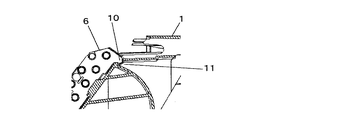
図3は、室内ユニットを右側から見たときの断面を示す縦断面図である。図4は、室内ユニットを右側から見たときの熱交換器3の取り付け状態を示す拡大縦断面図である。図3及び図4に基づいて、熱交換器3の右側における取り付け方法及び取り付け状態の詳細について説明する。なお、図3及び図4は、室内ユニット100が組み立てられた状態における構造を示している。
FIG. 3 is a longitudinal sectional view showing a section when the indoor unit is viewed from the right side. FIG. 4 is an enlarged vertical cross-sectional view showing a mounting state of the
筐体1に取り付けられる熱交換器3は、まず、図4に示すように熱交換器3の右側板6に形成されている引っ掛け部10が筐体1の右側の壁板20に形成されている取り付け穴11に引っ掛けられるようにして、熱交換器3の上部が筐体1に取り付けられる。したがって、容易に熱交換器3を筐体1に取り付けることが可能となる。それから、右側の壁板20に形成されているリブ9が右側板6に形成されているリブ用穴8に嵌合される。このようにして、熱交換器3の上下方向のがたつきを防止している。
As shown in FIG. 4, the
すなわち、右側板6の引っ掛け部10を右側の壁板20の取り付け穴11に引っ掛け、リブ用穴8にリブ9を嵌合するように押し込むという簡易な組み立て作業によって、熱交換器3の右側を取り付けることができる。したがって、組み立てにかかる手間や新たな機能部品の製造・追加が要求されず、空気調和機の製造にかかるコストを更に低減することが可能となる。また、熱交換器3の取り外しも容易なので、空気調和機が設置された後に行われるような熱交換器3の交換や修理、メンテナンス等にも手間がかからない。
That is, the right side of the
図5は、室内ユニットを左側から見たときの断面を示す縦断面図である。図6は、室内ユニットを左側から見たときの熱交換器3の取り付け状態を示す拡大縦断面図である。図5及び図6に基づいて、熱交換器3の左側の取り付け方法及び取り付け状態の詳細について説明する。つまり、熱交換器3の左側板7には、右側板6に形成されているリブ用穴8のような穴がなく、筐体1の左側の壁板30には、右側の壁板20に形成されているようなリブ9がないのである。
FIG. 5 is a longitudinal sectional view showing a section when the indoor unit is viewed from the left side. FIG. 6 is an enlarged vertical cross-sectional view showing a mounting state of the
筐体1に取り付けられる熱交換器3は、まず、図6に示すように熱交換器3の左側板7に形成されている引っ掛け部12が筐体1の左側の壁板30に形成されている取り付け穴13に引っ掛けられるようにして、熱交換器3の上部が筐体1に取り付けられる。ここまでは、右側の取り付け方と同様である。したがって、容易に熱交換器3を筐体1に取り付けることが可能となる。
As shown in FIG. 6, the
そして、右側の壁板20に形成されているリブ9が右側板6に形成されているリブ用穴8に嵌合された後に、図5に示すように左側で熱交換器3を固定するようになっているのである。つまり、熱交換器3は、熱交換器3の右側が支持された後に、筐体1の前面側よりもファン2の軸中心に合わせるようにして取り付け位置が決定され、固定されるようになっているのである。したがって、熱交換器3は、左右の上部が取り付けられた後に、右側で上下方向のがたつきを防止しつつ、ファン2の他方の軸を軸受32を介し凹部31に嵌合し、左側板7をネジ等の固定具で締め付けることによって左側が固定されるようになっている。
Then, after the
この実施の形態に係る空気調和機では、熱交換器3の右側板6を筐体1に簡易な作業で取り付けた後に、左側板7の配置を決定し固定するようになっている。したがって、熱交換器3を取り付けるための特別の作業工程を要することなく、容易に熱交換器3を取り付けて、固定することが可能となる。また、左側の壁板20には熱交換器3を固定するためのリブが形成されておらず、熱交換器3の左側板7にはリブを嵌合するための穴が形成されていないので、更に空気調和機の製造コストを低減することを可能としている。
In the air conditioner according to this embodiment, after the
すなわち、引っ掛け部10を取り付け穴11に引っ掛け、リブ用穴8にリブ9を押し込み(右側の取り付け)、その後、引っ掛け部12を取り付け穴13に引っ掛け左側板7の配置を決めて、固定具で左側板7を固定するのである(左側の取り付け及び全体の固定)。したがって、簡易な組み立て作業によって、熱交換器3を取り付け及び固定できる。また、組み立てにかかる手間や新たな機能部品の製造・追加が要求されず、空気調和機の製造にかかるコストを更に低減することが可能となる。さらに、熱交換器3の取り外しも容易なので、空気調和機が設置された後に行われるような熱交換器3の交換や修理、メンテナンス等にも手間がかからない。
That is, the
次に、熱交換器3の取り付け作業動作について説明する。
このように構成された空気調和機では、まず、筐体1にファン2を取り付けた後、熱交換器3の右側板6に形成されている引っ掛け部10を筐体1の右側の壁板20における取り付け穴11に引っ掛けて熱交換器3の右側上部を取り付け、右側板6のファン2の軸中心近傍に形成されているリブ用穴8に右側の壁板20のリブ9を装着することで熱交換器3の右側を支持する。その後、左側板7に形成されている引っ掛け部12を左側の壁板30の取り付け穴13に引っ掛け、熱交換器3の左側板7を筐体1の前面側よりファン2の中心軸に合わせて配置し、固定具で熱交換器3の左側を固定する。
Next, the operation of attaching the
In the air conditioner configured as described above, after the
熱交換器3を固定した後は、熱交換器3の右側板6及び左側板7に形成した引っ掛け部10及び引っ掛け部12が、重力方向に引っ張られるので、熱交換器3の上下方向への移動(がたつき)を抑制することができる。つまり、熱交換器3の右側においては、右側板6のリブ用穴8と右側の壁板20のリブ9との嵌合により熱交換器3の移動が制限され、また、左側においては、左側板7が筐体1のファン2の軸心近傍部に固定具により固定されて移動が制限される。したがって、左側板7の固定具を取り外さない限り、引っ掛け部10及び引っ掛け部12が外れることはない。
After fixing the
以上のように、熱交換器3を筺体1に固定するので、固定するための新たな機能部品を別に設けることなく、簡易に熱交換器3を取り付けることができるとともに、空気調和機の製造コストを低減することができる。また、複雑な構成にすることなく、熱交換器3を堅固に固定できる。さらに、熱交換器3の取り外しも容易なので、空気調和機が設置された後に行われるような熱交換器3の交換や修理、メンテナンス等にも手間がかからない。
As described above, since the
一方、熱交換器3の上部においては、筺体1との隙間が発生しにくく、熱交換器3を通らずにファン2側の風路へ外気が侵入することを防止することができる。そのために、風路内において、熱交換器3を通過した低温・低湿の状態となった冷気と、高温・高湿の状態の外気とが混入することがなく、そのために発生する着露を防ぐこともできる。また、熱交換器3を上部と下部とで分割して固定するために、一つの固定部分に応力が集中しにくく、空気調和機の搬送中等に発生する可能性の高い荷崩れや落下等の予想外の負荷がかかっても各構成部品の破損を軽減することができる。
On the other hand, in the upper part of the
1 筐体、2 ファン、3 熱交換器、4 ノズル、5 前面パネル、6 右側板、7 左側板、8 リブ用穴、9 リブ、10 引っ掛け部、11 取り付け穴、12 引っ掛け部、13 取り付け穴、20 壁板、21 軸用穴、30 壁板、31 凹部、32 軸受、100 室内ユニット。
1 housing, 2 fan, 3 heat exchanger, 4 nozzle, 5 front panel, 6 right side plate, 7 left side plate, 8 rib hole, 9 rib, 10 hooking part, 11 mounting hole, 12 hooking part, 13 mounting hole , 20 wall plate, 21 shaft hole, 30 wall plate, 31 recess, 32 bearing, 100 indoor unit.
Claims (3)
前記筐体の左右に設けられ、上部に穴部が形成された壁板と、
前記熱交換器の左右に設けられた側板と、
この側板に形成され、前記穴部に係合する引っ掛け部と、
前記穴部より下部で、前記各壁板の一方に形成されたリブと、
前記側板の一方に形成され、前記リブを受け入れて拘束するリブ用穴と、を備えた
ことを特徴とする空気調和機。 A heat exchanger that generates air for cooling and heating by heat exchange between refrigerant and air is an air conditioner that is attached to the front portion of a housing that forms an air passage inside,
Wall plates provided on the left and right sides of the housing, with holes formed in the upper part ,
Side plates provided on the left and right of the heat exchanger ;
A hook formed on the side plate and engaged with the hole,
A rib formed on one of the wall plates below the hole ,
An air conditioner , comprising: a rib hole formed on one of the side plates and receiving and restraining the rib .
ことを特徴とする請求項1に記載の空気調和機。 The air conditioner according to claim 1, wherein the hook portion has a hook allowance to be hooked in the direction of gravity.
前記壁板に設けられ、前記ファンの駆動軸を挿入支持する軸用穴とを、備え、
前記リブを前記軸用穴の近傍に形成した
ことを特徴とする請求項1又は2に記載の空気調和機。 A fan for sending air for heating and cooling generated by the heat exchanger into the room;
A shaft hole that is provided in the wall plate and inserts and supports the drive shaft of the fan;
The air conditioner according to claim 1 or 2, wherein the rib is formed in the vicinity of the shaft hole.
Priority Applications (1)
| Application Number | Priority Date | Filing Date | Title |
|---|---|---|---|
| JP2005313751A JP4334529B2 (en) | 2005-10-28 | 2005-10-28 | Air conditioner |
Applications Claiming Priority (1)
| Application Number | Priority Date | Filing Date | Title |
|---|---|---|---|
| JP2005313751A JP4334529B2 (en) | 2005-10-28 | 2005-10-28 | Air conditioner |
Publications (3)
| Publication Number | Publication Date |
|---|---|
| JP2007120862A JP2007120862A (en) | 2007-05-17 |
| JP2007120862A5 JP2007120862A5 (en) | 2007-08-09 |
| JP4334529B2 true JP4334529B2 (en) | 2009-09-30 |
Family
ID=38144902
Family Applications (1)
| Application Number | Title | Priority Date | Filing Date |
|---|---|---|---|
| JP2005313751A Expired - Fee Related JP4334529B2 (en) | 2005-10-28 | 2005-10-28 | Air conditioner |
Country Status (1)
| Country | Link |
|---|---|
| JP (1) | JP4334529B2 (en) |
Cited By (1)
| Publication number | Priority date | Publication date | Assignee | Title |
|---|---|---|---|---|
| CN104566629A (en) * | 2013-10-23 | 2015-04-29 | 珠海格力电器股份有限公司 | Air conditioner |
Families Citing this family (6)
| Publication number | Priority date | Publication date | Assignee | Title |
|---|---|---|---|---|
| JP4999809B2 (en) * | 2008-09-29 | 2012-08-15 | 三菱電機株式会社 | Air conditioner |
| JP2014052090A (en) * | 2012-09-05 | 2014-03-20 | Mitsubishi Electric Corp | Air conditioner |
| CN107621014A (en) * | 2017-09-26 | 2018-01-23 | 广东美的制冷设备有限公司 | Indoor apparatus of air conditioner and air conditioner |
| CN107559972A (en) * | 2017-09-26 | 2018-01-09 | 广东美的制冷设备有限公司 | Indoor apparatus of air conditioner and air conditioner |
| CN107420999A (en) * | 2017-09-26 | 2017-12-01 | 广东美的制冷设备有限公司 | Indoor apparatus of air conditioner and air conditioner |
| CN118066695B (en) * | 2024-04-19 | 2024-08-09 | 珠海格力电器股份有限公司 | Shaft sleeve, air deflector assembly, air conditioner and control method |
-
2005
- 2005-10-28 JP JP2005313751A patent/JP4334529B2/en not_active Expired - Fee Related
Cited By (2)
| Publication number | Priority date | Publication date | Assignee | Title |
|---|---|---|---|---|
| CN104566629A (en) * | 2013-10-23 | 2015-04-29 | 珠海格力电器股份有限公司 | Air conditioner |
| CN104566629B (en) * | 2013-10-23 | 2018-04-13 | 珠海格力电器股份有限公司 | Air conditioner |
Also Published As
| Publication number | Publication date |
|---|---|
| JP2007120862A (en) | 2007-05-17 |
Similar Documents
| Publication | Publication Date | Title |
|---|---|---|
| JP4334529B2 (en) | Air conditioner | |
| EP2056028B1 (en) | Outdoor unit of air conditioner | |
| KR101392541B1 (en) | Compressor fixation structure and outdoor unit for air conditioner comprising the same | |
| EP2604943A2 (en) | Wall-hanging air conditioner | |
| EP0769660A1 (en) | Motor fixing device for use in air conditioner | |
| MX2007002761A (en) | Device for fixing a heat transfer device, in particular a coolant radiator for motor vehicles. | |
| JP4899888B2 (en) | Panel structure | |
| WO2024040917A1 (en) | Base plate assembly for air conditioner, air conditioner, and recreational vehicle | |
| CN219063605U (en) | Window type air conditioner | |
| KR20060082335A (en) | Motor bracket of air-conditioner outdoor unit | |
| JP5509916B2 (en) | Air conditioner outdoor unit | |
| JP2008049915A (en) | Fan shroud mounting structure | |
| JP4522877B2 (en) | Air conditioner heat exchanger mounting structure | |
| KR101617890B1 (en) | Fan shroud mounting structure of vehicle | |
| KR20070066393A (en) | Housing of indoor unit for ceiling duct type air conditioner | |
| KR101015433B1 (en) | Structure for fixing fan assembly | |
| CN212299370U (en) | Volute installation structure and air conditioner | |
| CN213542828U (en) | A installation device and air conditioner for air conditioner | |
| KR101666222B1 (en) | Indoor unit of air conditioner | |
| KR200409400Y1 (en) | assembly structure of heat exchanger and fan shroud | |
| KR100576132B1 (en) | Indoor unit of air conditioner | |
| JP2006010303A (en) | Air conditioner | |
| KR100777403B1 (en) | Structure for fixing assembly of fan | |
| JPH10236171A (en) | Heat exchanger for automobile | |
| CN210345686U (en) | Motor fixing structure and air conditioner |
Legal Events
| Date | Code | Title | Description |
|---|---|---|---|
| A521 | Request for written amendment filed |
Free format text: JAPANESE INTERMEDIATE CODE: A523 Effective date: 20070622 |
|
| A621 | Written request for application examination |
Free format text: JAPANESE INTERMEDIATE CODE: A621 Effective date: 20070622 |
|
| A977 | Report on retrieval |
Free format text: JAPANESE INTERMEDIATE CODE: A971007 Effective date: 20080905 |
|
| A131 | Notification of reasons for refusal |
Free format text: JAPANESE INTERMEDIATE CODE: A131 Effective date: 20081111 |
|
| A521 | Request for written amendment filed |
Free format text: JAPANESE INTERMEDIATE CODE: A523 Effective date: 20081209 |
|
| TRDD | Decision of grant or rejection written | ||
| A01 | Written decision to grant a patent or to grant a registration (utility model) |
Free format text: JAPANESE INTERMEDIATE CODE: A01 Effective date: 20090616 |
|
| A01 | Written decision to grant a patent or to grant a registration (utility model) |
Free format text: JAPANESE INTERMEDIATE CODE: A01 |
|
| A61 | First payment of annual fees (during grant procedure) |
Free format text: JAPANESE INTERMEDIATE CODE: A61 Effective date: 20090623 |
|
| FPAY | Renewal fee payment (event date is renewal date of database) |
Free format text: PAYMENT UNTIL: 20120703 Year of fee payment: 3 |
|
| R150 | Certificate of patent or registration of utility model |
Ref document number: 4334529 Country of ref document: JP Free format text: JAPANESE INTERMEDIATE CODE: R150 Free format text: JAPANESE INTERMEDIATE CODE: R150 |
|
| FPAY | Renewal fee payment (event date is renewal date of database) |
Free format text: PAYMENT UNTIL: 20120703 Year of fee payment: 3 |
|
| FPAY | Renewal fee payment (event date is renewal date of database) |
Free format text: PAYMENT UNTIL: 20130703 Year of fee payment: 4 |
|
| R250 | Receipt of annual fees |
Free format text: JAPANESE INTERMEDIATE CODE: R250 |
|
| R250 | Receipt of annual fees |
Free format text: JAPANESE INTERMEDIATE CODE: R250 |
|
| R250 | Receipt of annual fees |
Free format text: JAPANESE INTERMEDIATE CODE: R250 |
|
| R250 | Receipt of annual fees |
Free format text: JAPANESE INTERMEDIATE CODE: R250 |
|
| R250 | Receipt of annual fees |
Free format text: JAPANESE INTERMEDIATE CODE: R250 |
|
| R250 | Receipt of annual fees |
Free format text: JAPANESE INTERMEDIATE CODE: R250 |
|
| R250 | Receipt of annual fees |
Free format text: JAPANESE INTERMEDIATE CODE: R250 |
|
| R250 | Receipt of annual fees |
Free format text: JAPANESE INTERMEDIATE CODE: R250 |
|
| LAPS | Cancellation because of no payment of annual fees |