JP4334192B2 - Coin handling machine - Google Patents
Coin handling machine Download PDFInfo
- Publication number
- JP4334192B2 JP4334192B2 JP2002241314A JP2002241314A JP4334192B2 JP 4334192 B2 JP4334192 B2 JP 4334192B2 JP 2002241314 A JP2002241314 A JP 2002241314A JP 2002241314 A JP2002241314 A JP 2002241314A JP 4334192 B2 JP4334192 B2 JP 4334192B2
- Authority
- JP
- Japan
- Prior art keywords
- coin
- support
- sorting
- coin sorting
- sorting member
- Prior art date
- Legal status (The legal status is an assumption and is not a legal conclusion. Google has not performed a legal analysis and makes no representation as to the accuracy of the status listed.)
- Expired - Fee Related
Links
Images


Classifications
-
- G—PHYSICS
- G07—CHECKING-DEVICES
- G07D—HANDLING OF COINS OR VALUABLE PAPERS, e.g. TESTING, SORTING BY DENOMINATIONS, COUNTING, DISPENSING, CHANGING OR DEPOSITING
- G07D5/00—Testing specially adapted to determine the identity or genuineness of coins, e.g. for segregating coins which are unacceptable or alien to a currency
- G07D5/08—Testing the magnetic or electric properties
-
- G—PHYSICS
- G07—CHECKING-DEVICES
- G07D—HANDLING OF COINS OR VALUABLE PAPERS, e.g. TESTING, SORTING BY DENOMINATIONS, COUNTING, DISPENSING, CHANGING OR DEPOSITING
- G07D3/00—Sorting a mixed bulk of coins into denominations
- G07D3/14—Apparatus driven under control of coin-sensing elements
-
- G—PHYSICS
- G07—CHECKING-DEVICES
- G07D—HANDLING OF COINS OR VALUABLE PAPERS, e.g. TESTING, SORTING BY DENOMINATIONS, COUNTING, DISPENSING, CHANGING OR DEPOSITING
- G07D3/00—Sorting a mixed bulk of coins into denominations
- G07D3/12—Sorting coins by means of stepped deflectors
- G07D3/121—Sorting coins by means of stepped deflectors arranged on inclined paths
- G07D3/123—Sorting coins by means of stepped deflectors arranged on inclined paths the coins being deflected off rails
- G07D3/125—Sorting coins by means of stepped deflectors arranged on inclined paths the coins being deflected off rails by moving deflectors
Landscapes
- Physics & Mathematics (AREA)
- General Physics & Mathematics (AREA)
- Testing Of Coins (AREA)
Description
【0001】
【発明の属する技術分野】
本発明は、硬貨処理機に関するものであり、さらに詳細には、装置を大型化させることなく、硬貨選別通路に供給された硬貨のうちから、所定の硬貨を、確実に、硬貨選別通路に形成された硬貨選別孔内に落下させて、選別することができる硬貨処理機に関するものである。
【0002】
【従来の技術】
硬貨選別通路に、径の小さい順に、複数の硬貨選別孔を形成し、処理すべき金種の硬貨のうち、径の小さい硬貨から、順に、硬貨選別孔に落下させて、硬貨を選別するように構成された硬貨処理機が知られている。
【0003】
しかしながら、このように構成された硬貨処理機にあっては、処理すべき硬貨の金種に等しい数の硬貨選別孔を、硬貨選別通路に形成することが必要不可欠になり、硬貨選別通路の長さが長くなって、硬貨処理機が大型化するという問題があった。
【0004】
そこで、米国特許第4,681,204号明細書は、硬貨選別通路に、少なくとも1つの硬貨選別孔を形成するとともに、硬貨選別通路内に突出する硬貨選別部材を設け、硬貨選別孔の上流側に設けられたセンサが、所定の硬貨を検出した時点で、硬貨選別部材を、硬貨選別通路の幅方向に移動させて、硬貨選別通路内に突出させ、所定の硬貨を、選択的に、硬貨選別孔内に落下させて、選別するように構成された硬貨処理機を提案している。
【0005】
この硬貨処理機によれば、硬貨処理機を大型化させることなく、所定の硬貨のみを、選択的に、硬貨選別孔内に落下させて、選別することが可能になるという利点がある。
【0006】
【発明が解決しようとする課題】
しかしながら、この硬貨処理機においては、硬貨選別部材を、硬貨選別通路の幅方向に移動させて、硬貨選別通路内に突出させ、所定の硬貨を、選択的に、硬貨選別孔内に落下させるように構成されているため、硬貨が搬送される際に、選別すべき硬貨と、選別すべき硬貨に先行する硬貨や、後続する硬貨との距離が小さい場合には、硬貨選別部材によって、選別すべき硬貨とともに、選別すべき硬貨に先行する硬貨や、後続する硬貨が、硬貨選別通路の幅方向に移動させられ、硬貨選別孔内に落下し、また、硬貨選別部材によって、選別すべき硬貨とともに、搬送ベルトも、硬貨選別通路の幅方向に移動させられるため、搬送ベルトの移動にともなって、選別すべき硬貨に先行する硬貨や、後続する硬貨も、硬貨選別通路の幅方向に移動させられて、硬貨選別孔内に落下することがあり、所望のように、硬貨を選別することができない場合があった。
【0007】
さらに、この硬貨処理機においては、硬貨選別部材が駆動されないときに、処理すべき最小径の硬貨が、硬貨選別孔内に落下することなく、硬貨選別孔を通過し、かつ、硬貨選別部材を駆動したときに、最大径の硬貨が、確実に、硬貨選別孔内に落下するように、硬貨選別孔を、硬貨の搬送方向に直交する方向における幅が、処理すべき最小径の硬貨の径未満で、かつ、処理すべき最大径の硬貨の径の1/2以上になるように形成することが必要不可欠であり、処理すべき硬貨の径に制限があるという問題があった。
【0008】
また、硬貨選別部材によって、硬貨選別通路の幅方向に移動させられた硬貨は自由落下によって、硬貨選別孔内に落下するように構成されているため、選別すべき硬貨が、確実に、硬貨選別孔内に落下するように、硬貨選別孔を、硬貨の搬送方向の長さが十分に長くなるように形成することが要求され、複数の硬貨選別孔を硬貨選別通路に形成する場合には、硬貨選別通路の長さが長くなり、硬貨の処理効率を向上させるために、硬貨の搬送速度を大きくするときは、硬貨選別通路の長さをさらに長くすることが必要になり、硬貨処理機が大型化するという問題もあった。
【0009】
したがって、本発明は、装置を大型化させることなく、硬貨選別通路に供給された硬貨のうちから、所定の硬貨を、確実に、硬貨選別通路に形成された硬貨選別孔内に落下させて、選別することができる硬貨処理機を提供することを目的とするものである。
【0010】
【課題を解決するための手段】
本発明のかかる目的は、硬貨処理機内に投入された硬貨を受け入れ、その回転によって生じた遠心力により、硬貨を一枚づつ、硬貨選別通路に送り出す回転円板と、その内壁により硬貨をガイドする基準ガイドレールと、硬貨を前記硬貨選別通路の表面との間で挟持しつつ、搬送する搬送ベルト手段と、硬貨の光学的性質および磁気的性質を検出するセンサとを備えた硬貨処理機において、さらに、前記基準ガイドレールの前記内壁に沿って、前記センサの下流側の前記硬貨選別通路に形成された硬貨選別孔と、前記硬貨選別通路の前記基準ガイドレール側の外部に設けられ、前記硬貨選別通路の長手方向軸線に平行な略水平軸まわりに、前記基準ガイドレールの近傍の前記硬貨選別孔内でのみ回転可能な硬貨選別部材とを備え、前記硬貨選別部材が、前記搬送ベルト手段によって、前記硬貨選別通路内を搬送される硬貨の一縁部のみを支持可能な硬貨支持面を有する少なくとも1つの硬貨支持部と、前記少なくとも1つの硬貨支持部と一体的に形成され、硬貨を押圧可能な少なくとも1つの硬貨押さえ部とを備え、さらに、前記少なくとも1つの硬貨支持部の前記硬貨支持面が、前記硬貨選別通路内を搬送される硬貨の一縁部のみを支持可能な硬貨支持位置と、前記硬貨支持面が、前記硬貨支持位置から退避し、硬貨を支持することができない退避位置との間で移動するように、前記硬貨選別部材を、前記水平軸まわりに回転させて、前記少なくとも1つの硬貨支持部を移動可能で、かつ、前記硬貨支持部の前記退避位置への回転に同期して、前記少なくとも1つの硬貨押さえ部を、硬貨を下方に向けて、押しやるように移動可能な硬貨選別部材駆動手段と、前記センサの検出信号に基づいて、前記硬貨選別部材駆動手段を駆動する制御手段を備え、前記制御手段が、前記センサの検出信号に基づいて、前記硬貨選別部材駆動手段を駆動して、前記硬貨選別部材の前記少なくとも1つの硬貨支持部の前記硬貨支持面によって支持されていた硬貨を、前記硬貨選別孔内に強制的に落下させて、選別可能に構成されたことを特徴とする硬貨処理機によって達成される。
【0011】
本発明によれば、硬貨処理機は、基準ガイドレールの内壁に沿って、センサの下流側の硬貨選別通路に形成された硬貨選別孔と、硬貨選別通路の基準ガイドレール側の外部に設けられ、硬貨選別通路の長手方向軸線に平行な略水平軸まわりに、前記基準ガイドレールの近傍の前記硬貨選別孔内でのみ回転可能な硬貨選別部材とを備え、硬貨選別部材が、搬送ベルト手段によって、硬貨選別通路内を搬送される硬貨の一縁部のみを支持可能な硬貨支持面を有する少なくとも1つの硬貨支持部と、少なくとも1つの硬貨支持部と一体的に形成され、硬貨を押圧可能な少なくとも1つの硬貨押さえ部とを備え、さらに、少なくとも1つの硬貨支持部の硬貨支持面が、硬貨選別通路内を搬送される硬貨の一縁部のみを支持可能な硬貨支持位置と、硬貨支持面が、硬貨支持位置から退避し、硬貨を支持することができない退避位置との間で移動するように、硬貨選別部材を、水平軸まわりに回転させて、少なくとも1つの硬貨支持部を移動可能で、かつ、硬貨支持部の退避位置への回転に同期して、少なくとも1つの硬貨押さえ部を、硬貨を下方に向けて、押しやるように移動可能な硬貨選別部材駆動手段と、センサの検出信号に基づいて、硬貨選別部材駆動手段を駆動する制御手段を備えているから、センサの検出信号に基づいて、硬貨選別孔内に落下させて、選別すべき硬貨を検出したときに、制御手段が、硬貨支持面が、硬貨支持位置から退避し、硬貨を支持することができない退避位置に、少なくとも1つの硬貨支持部を移動させて、硬貨支持部の硬貨支持面による硬貨の支持を解除し、硬貨支持面の退避位置への移動に同期して、硬貨押さえ部を、硬貨を下方に向けて、押しやるように移動させるように、硬貨選別部材駆動手段を駆動することによって、硬貨支持面によって支持されていた硬貨を、硬貨選別孔内に強制的に落下させることが可能になるから、選別すべき硬貨を、確実に、硬貨選別孔内に落下させて、選別することが可能になる。
【0012】
また、本発明によれば、選別すべき硬貨を、硬貨選別孔内に強制的に落下させることができるから、選別すべき硬貨に先行する硬貨や、後続する硬貨が、選別すべき硬貨に近接して、搬送されていても、選別すべき硬貨のみを、確実に、硬貨選別孔内に落下させて、選別することが可能になり、また、硬貨選別部材によって、搬送ベルト手段が、硬貨選別通路の幅方向に移動されて、選別すべき硬貨に先行する硬貨や、後続する硬貨が、硬貨選別孔内に落下することもなく、したがって、選別すべき硬貨のみを、確実に、硬貨選別孔内に落下させて、選別することが可能になる。
【0013】
さらに、本発明によれば、選別すべき硬貨を、硬貨選別孔内に強制的に落下させることができるから、硬貨の搬送方向における硬貨選別孔の長さを十分に長くしなくても、選別すべき硬貨を、確実に、硬貨選別孔内に落下させて、選別することができ、したがって、硬貨の処理効率を向上させるために、硬貨の搬送速度を増大させても、硬貨選別通路の長さを長くする必要がないから、硬貨処理機を大幅に小型化することが可能になる。
【0015】
加えて、本発明によれば、センサの検出信号に基づいて、硬貨選別孔内に落下させて、選別すべき硬貨を検出したときに、硬貨選別部材を、略水平軸まわりに回転させることによって、速やかに、硬貨支持部を退避位置に移動させて、硬貨の硬貨支持面による硬貨の支持を解除するとともに、少なくとも1つの硬貨支持部と一体的に形成された硬貨押さえ部により、硬貨支持面によって支持されなくなった硬貨を下方に向けて、押しやって、硬貨選別孔内に強制的に落下させることができるから、選別すべき硬貨を、確実に、硬貨選別孔内に落下させて、選別することが可能になる。
【0016】
本発明のさらに好ましい実施態様においては、前記硬貨選別部材が単一の硬貨支持部と硬貨押さえ部を備え、前記硬貨支持部が、前記硬貨支持面に略直交する側壁部を有し、前記硬貨選別部材の前記硬貨支持部が、前記硬貨支持位置に位置しているときに、前記硬貨支持部の前記側壁部が、前記基準ガイドレールの前記内壁に滑らかに連なり、前記硬貨選別孔の前記硬貨選別通路側の側部と、前記硬貨支持部の前記側壁部との間隔が、処理すべき最小径の硬貨の径未満になるように、前記硬貨選別孔が形成され、前記硬貨選別部材が設けられている。
【0017】
本発明のさらに好ましい実施態様によれば、硬貨支持部が、硬貨支持面に略直交する側壁部を有し、硬貨選別部材の硬貨支持部が、硬貨支持位置に位置しているときに、硬貨支持部の側壁部が、基準ガイドレールの内壁に滑らかに連なり、硬貨選別孔の硬貨選別通路側の側部と、硬貨支持部の側壁部との間隔が、処理すべき最小径の硬貨の径未満になるように、硬貨選別孔が形成され、硬貨選別部材が設けられているから、硬貨の搬送方向に直交する方向における硬貨選別孔の幅の下限は制限されず、したがって、処理すべき硬貨の径に制限が加えられることがなく、金種によって径が大きく異なる硬貨を、所望のように、選別することが可能になる。
【0018】
本発明のさらに好ましい実施態様においては、前記硬貨選別部材駆動手段が、ロータリーソレノイドによって構成されている。
【0019】
本発明のさらに好ましい実施態様によれば硬貨選別部材駆動手段が、ロータリーソレノイドによって構成されているから、硬貨選別部材を、略水平な軸まわりに、速やかに回転させることができ、したがって、硬貨支持部を退避位置に移動させて、硬貨の硬貨支持面による硬貨の支持を解除し、硬貨支持面の上方の硬貨支持部に一体的に取り付けられた硬貨押さえ部により、硬貨支持面によって支持されなくなった硬貨を、下方に向けて、押しやって、確実に、硬貨選別孔内に強制的に落下させ、選別することが可能になる。
【0020】
本発明のさらに好ましい実施態様においては、さらに、前記ロータリーソレノイドの出力軸に、一端部が固定されたアームであって、他端部が扇状断面をなすとともに、ギアが形成されたアームを備え、前記硬貨選別部材が、ギアが形成された扇状側断面を有する係合部を備え、前記係合部に形成された前記ギアが、前記アームの前記他端部に形成されたギアに係合し、前記ロータリーソレノイドの駆動力が前記硬貨選別部材に伝達可能に構成されている。
【0021】
本発明の別の好ましい実施態様においては、前記硬貨選別部材が、円筒部と、放射状に延びるように、前記円筒部に形成された複数の突出部を備え、前記複数の突出部がそれぞれ、前記硬貨選別部材が回転する方向に対して、上流側に位置する側面によって構成された硬貨支持部と、下流側に位置する側面によって構成された硬貨押さえ部とを備え、前記複数の硬貨支持部のうちの1つの硬貨支持部が前記硬貨支持位置に位置しているときに、前記1つの硬貨支持部が、前記搬送ベルト手段によって、前記硬貨選別通路内を搬送される硬貨の一縁部のみを支持可能な硬貨支持面を形成し、前記1つの硬貨支持部が前記退避位置に回転されるのに同期して、前記1つの硬貨支持部を構成する前記突出部の上流側に隣接する突出部の前記硬貨押さえ部が、前記退避位置に移動する前記1つの硬貨支持部によって支持されていた硬貨の上面を、下方に向けて、押しやる前記硬貨押さえ部を構成するようになっている。
【0022】
本発明の別の好ましい実施態様によれば、硬貨選別部材が、円筒部と、放射状に延びるように、円筒部に形成された複数の突出部を備え、複数の突出部がそれぞれ、硬貨選別部材が回転する方向に対して、上流側に位置する側面によって構成された硬貨支持部と、下流側に位置する側面によって構成された硬貨押さえ部とを備え、複数の硬貨支持部のうちの1つの硬貨支持部が硬貨支持位置に位置しているときに、1つの硬貨支持部が、搬送ベルト手段によって、硬貨選別通路内を搬送される硬貨の一縁部のみを支持可能な硬貨支持面を形成し、1つの硬貨支持部が退避位置に回転されるのに同期して、1つの硬貨支持部を構成する突出部の上流側に隣接する突出部の硬貨押さえ部が、退避位置に移動する1つの硬貨支持部によって支持されていた硬貨の上面を、下方に向けて、押しやる硬貨押さえ部を構成するから、センサの検出信号に基づいて、硬貨選別孔内に落下させて、選別すべき硬貨を検出したときに、硬貨選別部材を、略水平軸まわりに、回転させることによって、速やかに、1つの硬貨支持部を退避位置に移動させて、その硬貨支持部の硬貨支持面による硬貨の支持を解除するとともに、1つの硬貨支持部を構成する突出部の上流側に隣接する突出部の硬貨押さえ部により、1つの硬貨支持部の硬貨支持面によって支持されなくなった硬貨を、下方に向けて、押しやって、硬貨選別孔内に強制的に落下させることができるから、選別すべき硬貨を、確実に、硬貨選別孔内に落下させて、選別することが可能になる。
【0025】
本発明のさらに好ましい実施態様においては、前記硬貨選別部材の前記硬貨支持部が、前記硬貨支持位置に位置しているときに、前記硬貨選別部材の前記円筒部の周面が、前記基準ガイドレールの前記内壁に滑らかに連なり、前記硬貨選別孔の前記硬貨選別通路側の側部との間隔が、処理すべき最小径の硬貨の径未満になるように、前記硬貨選別孔が形成され、前記硬貨選別部材が設けられている。
【0026】
本発明のさらに好ましい実施態様によれば、硬貨選別部材の硬貨支持部が、硬貨支持位置に位置しているときに、硬貨選別部材の円筒部の周面が、基準ガイドレールの内壁に滑らかに連なり、硬貨選別孔の硬貨選別通路側の側部との間隔が、処理すべき最小径の硬貨の径未満になるように、硬貨選別孔が形成され、硬貨選別部材が設けられているから、硬貨の搬送方向に直交する方向における硬貨選別孔の幅の下限は制限されず、したがって、処理すべき硬貨の径に制限が加えられることがなく、金種によって径が大きく異なる硬貨を、所望のように、選別することが可能になる。
【0027】
本発明のさらに好ましい実施態様においては、前記硬貨選別部材駆動手段が、パルスモータによって構成されている。
【0028】
本発明のさらに好ましい実施態様においては、前記パルスモータの出力軸に、周面にギアが形成されたドラムが固定され、前記硬貨選別部材に、周面に、ギアが形成された円柱状の係合部材が一体的に取り付けられ、前記係合部材の周面に形成された前記ギアと、前記ドラムの周面に形成された前記ギアとが係合し、前記パルスモータの駆動力が、前記硬貨選別部材に伝達可能に構成されている。
【0029】
本発明のさらに好ましい実施態様においては、前記複数の硬貨支持部が、順次、前記硬貨支持位置に位置するように、前記パルスモータが、前記硬貨選別部材を回転可能に構成されている。
【0030】
本発明のさらに好ましい実施態様によれば、複数の硬貨支持部が、順次、硬貨支持位置に位置するように、パルスモータが、硬貨選別部材を回転可能に構成されているから、選別すべき硬貨が、次々に、搬送されて来ても、確実に、硬貨選別孔内に落下させて、選別することが可能になる。
【0031】
【発明の実施の形態】
以下、添付図面に基づいて、本発明の好ましい実施態様につき、詳細に説明を加える。
【0032】
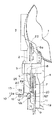
図1は、本発明の好ましい実施態様にかかる硬貨処理機の硬貨選別通路の略平面図であり、図2は、図1の略左側面図である。
【0033】
本実施態様においては、硬貨処理機は、オペレータによって指定された金種の硬貨を包装可能に構成されている。
【0034】
図1に示されるように、本実施態様にかかる硬貨処理機は、硬貨処理機内に投入された硬貨Cを、硬貨搬送手段(図示せず)を介して、その表面上で受け取る回転円板1と、回転円板1に接続された硬貨選別通路2を備えている。
【0035】
硬貨選別通路2は、硬貨Cを、その硬貨選別通路2側の内壁に沿ってガイドする基準ガイドレール3と、基準ガイドレール3に対向して配置されたガイドレール4を備え、回転円板1との接続部の近傍には、硬貨Cの径を光学的に検出し、硬貨Cの材質を磁気的に検出するセンサ5を備えている。
【0036】
さらに、硬貨選別通路2には、プーリ6aおよびプーリ6bに懸架され、硬貨Cを、硬貨選別通路2の表面との間に挟持して、搬送する第一の搬送ベルト8と、プーリ7およびプーリ(図示せず)に懸架され、硬貨Cを、硬貨選別通路2の表面との間に挟持して、第一の搬送ベルト8より高速で搬送する第二の搬送ベルト9が設けられており、第二の搬送ベルト9の下方の硬貨選別通路2には、硬貨選別装置10が設けられている。
【0037】
図3は、本発明の好ましい実施態様にかかる硬貨処理機の硬貨選別装置の略平面図である。
【0038】
図3に示されるように、硬貨選別装置10は、基準ガイドレール3の内壁に沿って、硬貨選別通路2に形成された硬貨選別孔11と、この硬貨選別孔11の基準ガイドレール3側の側部近傍に設けられた硬貨選別部材12と、ロータリーソレノイド13と、一端部が、ロータリーソレノイド13の出力軸13aに固定されたアーム16を備えている。
【0039】
図4は、硬貨選別装置10の略側面図である。
【0040】
図4に示されるように、アーム16の先端部16aは扇状側断面を有し、アーム16の先端部16aには、ギア16bが形成されている。
【0041】
図4に示されるように、硬貨選別部材12は、水平軸12aに回動自在に取り付けられており、アーム16の先端部16aに形成されたギア16bと噛み合うギア12dが形成された扇状側断面を有する係合部12bを備えている。
【0042】
硬貨選別部材12は、硬貨選別通路2内を搬送される硬貨Cの縁部を支持する硬貨支持部12fを有する硬貨支持部材12cを備え、硬貨支持部材12cの硬貨支持部12fが、硬貨Cの縁部を支持する硬貨支持位置と、硬貨支持部材12cの硬貨支持部12fが、硬貨支持位置から退避し、硬貨Cを硬貨選別孔11内に落下させる退避位置との間で、水平軸12aまわりに回動可能に構成されている。
【0043】
本実施態様においては、硬貨選別部材12が硬貨支持位置に位置しているときに、硬貨選別孔11のガイドレール4側の端部と、硬貨支持部材12cの硬貨支持部12fの基準ガイドレール3側の内壁面との距離が、処理すべき最小径の硬貨Cの径よりもわずかに小さくなるように、硬貨選別孔11が形成され、硬貨選別部材12が硬貨支持位置に位置しているときに、硬貨支持部材12cの硬貨支持部12fの側壁が、基準ガイドレール3のガイド面と滑らかに連なり、かつ、硬貨支持部材12cの硬貨支持部12fの上面が、硬貨選別通路2の上面と同一面内に位置するように、硬貨選別部材12が配置されている。
【0044】
図4に示されるように、硬貨選別部材12の硬貨支持部材12cには、硬貨押さえ部材12eが一体的に取り付けられている。
【0045】
図5は、退避位置に位置している硬貨選別部材12の略側面図である。
【0046】
図5に示されるように、ロータリーソレノイド13が駆動されると、ロータリーソレノイド13の出力軸13aが、図4および図5において、反時計回りに回転され、アーム16が、反時計回りに揺動される。
【0047】
その結果、ロータリーソレノイド13の出力軸13の回転力が、アーム16の先端部16aに形成されたギア16bおよびこれに噛み合う係合部12bのギア12dによって、硬貨選別部材12に伝達されて、硬貨選別部材12が、水平軸12aまわりに、図4および図5において、時計方向に回転される。
【0048】
したがって、選別すべき硬貨Cの縁部が、硬貨選別部材12を構成する硬貨支持部材12cの硬貨支持部12fに支持されているタイミングで、ロータリーソレノイド13を駆動して、硬貨支持部材12cを退避位置に移動させることによって、硬貨Cの縁部が、硬貨支持部材12cの硬貨支持部12fによって支持されなくなり、さらに、硬貨支持部材12cに一体的に取り付けられた硬貨押さえ部12eによって、硬貨Cが、下方に向けて、押しやられて、硬貨選別孔11内に強制的に落下させられ、所望のように、硬貨Cを選別することができるように構成されている。
【0049】
図1および図3に示されるように、硬貨選別孔11の直上流側の硬貨選別通路2には、硬貨Cの通過を検出する硬貨センサ20が設けられ、硬貨選別孔11の直下流側の硬貨選別通路2には、その上を通過した硬貨Cの枚数を計数するセンサ21が設けられている。
【0050】
第一の搬送ベルト8が懸架されているプーリ6bと、第二の搬送ベルト9が懸架されているプーリ7とは一体に形成されるとともに、プーリ6bの径は、プーリ7の径に比して、小さく形成されており、その結果、第二の搬送ベルト9の駆動速度は、第一の搬送ベルト8よりも大きくなり、第二の搬送ベルト9によって、硬貨Cの搬送速度が加速され、硬貨選別通路2内を、連続して送られる硬貨Cの間の間隔が大きくされて、硬貨Cを確実に選別することができるように構成されている。
【0051】
図1において、参照番号22は、二枚以上の硬貨Cが、同時に、回転円板1から硬貨選別通路2に送り出されるの防止するため、処理すべき硬貨Cの厚みに応じて、回転円板1の表面との間隙を設定する間隙設定部材であり、また、図2において、参照番号23は、第一の搬送ベルト8および第二の搬送ベルト9を、硬貨選別通路2の表面に押圧する押さえローラである。
【0052】
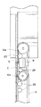
図6は、第一の搬送ベルト8および第二の搬送ベルト9を取り去った硬貨処理機の略平面図である。
【0053】
図6に示されるように、基準ガイドレール3は、硬貨Cが、確実に、その硬貨選別通路2側の内壁に沿ってガイドされるように、第一の搬送ベルトル8の長手方向に対して、その側面が傾きを有するように形成された斜壁部分25を有しており、ガイドレール4もまた、基準ガイドレール3との間隔が一定になるように、第一の搬送ベルト8の長手方向に対して、その内壁が傾きを有するように形成された斜壁部分を有している。
【0054】
図示されてはいないが、硬貨選別通路2の下流端部には、一対の集積ドラムを備え、所定枚数の硬貨Cを集積する硬貨集積部が設けられ、硬貨集積部の下方には、複数の包装ローラを備え、硬貨集積部において集積された所定枚数の硬貨Cを包装する硬貨包装部が設けられている。
【0055】
図7は、本発明の好ましい実施態様にかかる硬貨処理機の入力系、検出系、駆動系、制御系および表示系のブロックダイアグラムである。
【0056】
図7に示されるように、本実施態様にかかる硬貨処理機の入力系は、包装すべき硬貨Cの金種を入力する金種設定手段30と、硬貨Cの処理を開始させるスタート手段31を備え、硬貨処理機の検出系は、光学的に硬貨Cの径、色、表面パターンを検出するとともに、磁気的に硬貨Cの材質を検出するセンサ5と、硬貨を検出する硬貨センサ20と、その上を通過した硬貨Cの枚数を計数するセンサ21を備えている。
【0057】
図7に示されるように、本実施態様にかかる硬貨処理機の駆動系は、回転円板1を回転させる回転円板モータ35と、第一の搬送ベルト8および第二の搬送ベルト9を駆動させる搬送ベルトモータ36と、アーム16を介して、硬貨選別部材12を回転させるロータリーソレノイド13を備えている。
【0058】
図7に示されるように、本実施態様にかかる硬貨処理機の制御系は、硬貨処理機全体の動作を制御するコントロールユニット40と、制御プログラムならびに処理すべき硬貨Cの径、色および表面パターンに関する光学基準データおよび磁気的な性質に関する磁気基準データを記憶するROM41と、各種データを記憶するRAM42を備え、硬貨処理機の表示系は、硬貨処理の結果などを表示するディスプレイパネル44を備えている。
【0059】
以上のように構成された本発明の実施例にかかる硬貨処理機は、以下のようにして、指定された金種の硬貨C以外の硬貨Cを選別して、回収するとともに、指定された金種の硬貨Cを包装する。
【0060】
硬貨Cの処理を開始するにあたり、まず、オペレータによって、金種設定手段30が操作されて、包装すべき硬貨Cの金種が設定され、次いで、スタート手段31が操作される。
【0061】
オペレータによって、包装すべき硬貨Cの金種が設定されると、金種設定手段30から、金種設定信号が、コントロールユニット40に出力される。
【0062】
金種設定手段30から、金種設定信号が入力されると、コントロールユニット40は、入力された金種設定信号に基づいて、ROM41から、包装すべき硬貨Cの径、色、表面パターンに関する光学基準データおよび磁気的な性質に関する磁気基準データを読み出して、RAM42に記憶させる。
【0063】
スタート手段31から、スタート信号が入力されると、コントロールユニット40は、回転円板モータ35および搬送ベルトモータ36に駆動信号を出力して、回転円板1を回転させるとともに、第一の搬送ベルト8および第二の搬送ベルト9を駆動させる。
【0064】
次いで、オペレータによって、硬貨が硬貨投入部(図示せず)に投入される。
【0065】
硬貨投入部(図示せず)から、硬貨処理機に投入された硬貨Cは、硬貨搬送手段(図示せず)により、回転円板1上に送られ、回転円板1の回転によって生じた遠心力により、硬貨選別通路2内に送られる。この際、間隙設定部材22によって、硬貨Cは、一枚づつ、硬貨選別通路2に送られ、硬貨Cの二枚送りが防止される。
【0066】
硬貨選別通路2に送られた硬貨Cは、センサ5により、その径、色、表面パターンおよび磁気的な性質が検出され、センサ5から、検出信号が、コントロールユニット40に出力される。
【0067】
コントロールユニット40は、センサ5から入力された検出信号に基づいて、硬貨Cの径、色、表面パターンに関する光学検出データおよび硬貨Cの磁気的な性質に関する磁気検出データを、RAM42に記憶された光学基準データおよび磁気基準データとを比較する。
【0068】
その結果、硬貨Cの径、色、表面パターンに関する光学検出データと光学基準データとが実質的に一致すると認められ、かつ、硬貨Cの磁気的な性質に関する磁気検出データと磁気基準データとが実質的に一致すると認められるときは、コントロールユニット40は、その硬貨Cは、金種設定手段30により設定された包装すべき金種の硬貨Cであると判定して、その旨を示すデータを、RAM42に書き込む。
【0069】
これに対して、硬貨Cが、金種設定手段30により設定された包装すべき金種の硬貨Cではないと判定したときは、コントロールユニット40は、その旨を示すデータを、RAM42に書き込む。
【0070】
硬貨Cが、第一の搬送ベルト8および第二の搬送ベルト9によって、さらに、基準ガイドレール3に沿って、硬貨選別通路2内を搬送され、硬貨センサ20によって、硬貨Cが検出されると、硬貨センサ20から、硬貨検出信号が、コントロールユニット40に出力される。
【0071】
コントロールユニット40は、硬貨センサ20から、硬貨検出信号が入力されると、RAM42にアクセスして、その硬貨Cが、包装すべき金種の硬貨Cか否かを判定し、包装すべき金種の硬貨Cであると判定したときは、何の信号も出力しない。
【0072】
したがって、包装すべき金種の硬貨Cは、硬貨センサ20に検出された後、基準ガイドレール3および基準ガイドレール3のガイド面と滑らかに連なるように配置された硬貨選別部材12を構成する硬貨支持部材12cの硬貨支持部12fの側壁に沿って、硬貨選別通路2内を搬送され、図4に示されるように、選別すべき硬貨Cは、一方の縁部が、硬貨支持位置に位置している硬貨選別部材12を構成する硬貨支持部材12cの硬貨支持部12fによって支持され、他方の縁部が、硬貨選別通路2に上面によって支持されつつ、硬貨選別通路2内を搬送されて、硬貨選別装置10を通過する。
【0073】
これに対して、RAM42に記憶されたデータに基づき、その硬貨Cが、包装すべき金種の硬貨C以外の硬貨、すなわち、包装すべき金種の硬貨C以外の金種の真正な硬貨Cもしくは偽貨、外国硬貨などの受け入れ不能な硬貨Cであると判定したときは、コントロールユニット40は、その硬貨Cが硬貨センサ20を通過するタイミングで、ロータリーソレノイド13に駆動信号を出力する。
【0074】
コントロールユニット40から、駆動信号が、ロータリーソレノイド13に出力されると、ロータリーソレノイド13が駆動され、ロータリーソレノイド13の出力軸13aが、図4および図5において、反時計方向に回転される。
【0075】
その結果、アーム16が、ロータリーソレノイド13の出力軸13aまわりに、図4および図5において、反時計方向に揺動され、ロータリーソレノイド13の出力軸13の回転力が、アーム16の先端部16aに形成されたギアおよびこれに噛み合う係合部12bのギアによって、硬貨選別部材12に伝達されて、硬貨選別部材12が、水平軸12aまわりに、図4および図5において、時計方向に回転される。
【0076】
したがって、包装すべき金種の硬貨C以外の金種の真正な硬貨Cもしくは偽貨、外国硬貨などの受け入れ不能な硬貨Cは、硬貨センサ20に検出された後、基準ガイドレール3および基準ガイドレール3のガイド面と滑らかに連なるように配置された硬貨選別部材12を構成する硬貨支持部材12cの硬貨支持部12fに沿って、硬貨選別通路2内を搬送され、図4に示されるように、一方の縁部が、硬貨支持位置に位置している硬貨支持部材12cの硬貨支持部12fによって支持され、他方の縁部が、硬貨選別通路2に上面によって支持されるが、その硬貨Cが硬貨センサ20を通過するタイミングで、硬貨選別部材12が、水平軸12aまわりに、図4および図5において、時計方向に回転され、硬貨支持部材12cが退避位置に移動するため、図5に示されるように、硬貨Cの一方の縁部が、硬貨支持部材12cの硬貨支持部12fによって支持されなくなり、さらに、硬貨選別部12cに一体的に取り付けられた硬貨押さえ部材12eが、水平軸12aまわりに、図4および図5において、時計方向に回転されるため、硬貨Cは、硬貨押さえ部材12eによって、下方に向けて、押しやられ、強制的に、硬貨選別孔11内に落下させられて、選別され、硬貨回収ボックス(図示せず)内に回収される。
【0077】
このように、本実施態様においては、硬貨支持部材12cおよびこれに一体的に取り付けられた硬貨押さえ部材12eを、水平軸12aまわりに、図4および図5において、時計方向に回転させて、硬貨選別部材12の硬貨支持部材12cを退避位置に位置させることによって、包装すべき金種の硬貨C以外の金種の真正な硬貨Cもしくは偽貨、外国硬貨などの受け入れ不能な硬貨Cを、硬貨選別孔11内に強制的に落下させて、選別することができるように構成されているから、硬貨選別孔11内に落下させて、選別すべき硬貨に先行する硬貨Cや、後続する硬貨Cが、選別すべき硬貨Cに近接して、搬送されていても、選別すべき硬貨Cのみを、確実に、硬貨選別孔11内に落下させて、選別することが可能になり、また、硬貨選別部材12によって、第一の搬送ベルト8および第二の搬送ベルト9が、硬貨選別通路2の幅方向に移動されて、選別すべき硬貨に先行する硬貨Cや、後続する硬貨Cが、硬貨選別孔11内に落下することもなく、したがって、選別すべき硬貨Cのみを、確実に、硬貨選別孔11内に落下させて、選別することが可能になる。
【0078】
ロータリーソレノイド13を駆動してから、所定時間が経過すると、コントロールユニット40は、ロータリーソレノイド13に駆動停止信号を出力する。
【0079】
その結果、ロータリーソレノイド13の出力軸13aが元の回転位置に復帰し、それにともなって、アーム16が、ロータリーソレノイド13の出力軸13aまわりに、図4および図5において、時計方向に揺動され、硬貨選別部材12が、水平軸12aまわりに、図4および図5において、反時計方向に回転されて、硬貨支持部材12cが硬貨支持位置に復帰する。
【0080】
これに対して、硬貨選別装置10を通過した包装すべき硬貨Cは、センサ21上を通過して、その枚数が計数され、硬貨選別通路2の下流端部に接続された硬貨集積部(図示せず)に送られて、集積される。
【0081】
センサ21が、硬貨Cを検出するたびに、硬貨検出信号がコントロールユニット40に出力され、コントロールユニット40は、センサ21から入力される硬貨検出信号に基づいて、センサ21を通過した包装すべき硬貨Cの枚数を計数して、計数値をRAM42に書き込み、RAM42に書き込まれた包装すべき硬貨Cの計数値に基づき、所定枚数の包装すべき硬貨Cが、硬貨集積部に送られたと判定すると、ストッパ(図示せず)を、硬貨選別通路2内に突出させて、後続する硬貨Cが、硬貨集積部内に送られることを阻止する。
【0082】
硬貨集積部に送られて、集積された所定枚数の硬貨Cは、硬貨包装部(図示せず)に送られて、複数の包装ローラによって、その周囲に、包装紙が巻回され、包装硬貨ロールが生成される。
【0083】
一方、コントロールユニット40は、硬貨センサ20が、包装すべき金種の硬貨以外の硬貨Cを検出するたびに、ロータリーソレノイド13に、所定の時間にわたり、駆動信号を出力して、硬貨選別部材12を水平軸12aまわりに回転させ、硬貨支持部材12cを退避位置に移動させ、その結果、包装すべき金種の硬貨以外の硬貨Cはすべて、硬貨選別装置10によって、硬貨選別孔11内に落下させられて、選別され、硬貨回収ボックス(図示せず)内に回収される。
【0084】
こうして、すべての包装すべき硬貨が、所定枚数づつ、硬貨集積部に送られ、硬貨包装部によって、包装され、包装すべき金種の硬貨以外の硬貨Cがすべて、硬貨選別装置10によって選別されて、硬貨選別孔11内に落下し、硬貨回収ボックス(図示せず)内に回収されると、硬貨処理機による硬貨Cの処理が完了する。
【0085】
本実施態様によれば、硬貨選別孔11内に落下させて、選別すべき硬貨Cは、まず、その一方の縁部が、硬貨選別部材12を構成する硬貨支持部材12cの硬貨支持部12fによって支持されるとともに、その他方の縁部が、硬貨選別通路2の上面によって支持され、次いで、ロータリーソレノイド13が駆動されて、アーム16が、ロータリーソレノイド13の出力軸13aまわりに、図4および図5において、反時計方向に揺動され、硬貨支持部材12cおよびこれに一体的に取り付けられた硬貨押さえ部材12eが、水平軸12aまわりに、図4および図5において、時計回りに回転されて、硬貨選別部材12のこ支持部材12cが退避位置に移動することによって、選別すべき硬貨Cの一方の縁部が、硬貨支持部材12cの硬貨支持部12fによって支持されなくなり、さらに、硬貨選別部材12の硬貨支持部材12cに一体的に取り付けられた硬貨押さえ部材12eによって、選別すべき硬貨Cが、下方に向けて、押しやられて、強制的に、硬貨選別孔11内に落下させられるから、確実に、選別すべき硬貨Cを、硬貨選別孔11内に落下させて、選別することが可能になる。
【0086】
また、本実施態様によれば、硬貨支持部材12cおよびこれに一体的に取り付けられた硬貨押さえ部12eを、水平軸12aまわりに、図4および図5において、時計方向に回転させて、硬貨支持部材12を退避位置に移動させることによって、選別すべき硬貨Cを、硬貨選別孔11内に強制的に落下させて、選別するように構成されているから、選別すべき硬貨に先行する硬貨Cや、後続する硬貨Cが、選別すべき硬貨Cに近接して、搬送されていても、選別すべき硬貨Cのみを、確実に、硬貨選別孔11内に落下させて、選別することが可能になり、また、硬貨選別部材12によって、第一の搬送ベルト8および第二の搬送ベルト9が、硬貨選別通路2の幅方向に移動されて、選別すべき硬貨に先行する硬貨Cや、後続する硬貨Cが、硬貨選別孔11内に落下することもなく、したがって、選別すべき硬貨Cのみを、確実に、硬貨選別孔11内に落下させて、選別することが可能になる。
【0087】
さらに、本実施態様によれば、選別すべき硬貨Cは、硬貨支持部材12cに一体的に取り付けられた硬貨押さえ部12eによって、下方に向けて、押しやられ、強制的に、硬貨選別孔11内に落下させられるから、硬貨Cの搬送方向における硬貨選別孔11の長さを十分に長くしなくても、選別すべき硬貨Cを、確実に、硬貨選別孔11内に落下させて、選別することができ、したがって、硬貨Cの処理効率を向上させるために、硬貨Cの搬送速度を増大させても、硬貨選別通路2の長さを長くする必要がないから、硬貨処理機を大幅に小型化することが可能になる。
【0088】
また、本実施態様によれば、硬貨Cの搬送方向に直交する方向における幅が、処理すべき最小径の硬貨Cの径未満になるように、硬貨選別孔11を形成すればよく、下限値に制限がないから、処理すべき硬貨Cの径に制限が加えられることがなく、金種によって径が大きく異なる硬貨Cを、所望のように、選別することが可能になる。
【0089】
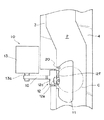
図8は、本発明の別の好ましい実施態様にかかる硬貨処理機の硬貨選別装置の略側面図である。
【0090】
本実施態様にかかる硬貨処理機は、硬貨処理機に投入された硬貨Cの中から、偽造硬貨、外国硬貨などの受け入れ不能な硬貨Cおよび所定レベルを越えて、汚損された硬貨Cを選別して、別個に回収するように構成されている。
【0091】
図8に示されるように、本実施態様にかかる硬貨処理機の硬貨選別装置50は、硬貨押さえ部材12eが一体的に取り付けられた硬貨支持部材12cを備え、水平軸12aに回動な硬貨選別部材12に代えて、円筒部51と、円筒部51から放射状に延びた6つの硬貨支持部52を備え、水平軸53まわりに回転可能な円筒状の硬貨選別部材54を備えている。
【0092】
図8には図示されていないが、硬貨選別部材53の水平軸53には、周囲に、ギアが形成された円柱状の係合部材が一体的に取り付けられ、係合部材の周囲に形成されたギアは、ドラム55の周面に形成されたギア55aと係合している。
【0093】
硬貨選別装置50は、さらに、パルスモータ(図示せず)を備え、ドラム55は、パルスモータの出力軸56に固定され、パルスモータによって、出力軸56まわりに、図8において、反時計方向に、間欠的に、回転されるように構成されている。
【0094】
したがって、パルスモータの回転力が、ドラム55の周面に形成されたギア55aおよび係合部材の周囲に形成されたギアを介して、硬貨選別部材54に伝達され、硬貨選別部材54が、図8において、水平軸53まわりに、時計方向に間欠的に回転されるように構成されている。
【0095】
図8に示されるように、各硬貨支持部52は、その表面で、硬貨Cを支持する硬貨支持面52aと、硬貨Cの上面を押圧して、硬貨Cを、硬貨選別孔57内に強制的に落下させる硬貨押さえ部52bとを備えている。
【0096】
硬貨選別部材54は、通常は、図8に示されるように、6つの硬貨支持部52のいずれかが、その硬貨支持面52aが硬貨選別通路2の上面と同一面内に位置し、硬貨Cの一縁部を支持可能な硬貨支持位置に保持され、硬貨Cを硬貨選別孔57内に落下させて、選別するときは、パルスモータによって、次に、硬貨支持位置に位置すべき硬貨支持部52の硬貨支持面52aが、硬貨選別通路2の上面と同一面内に位置するまで、間欠的に回転されるように構成されており、硬貨選別部材54が、パルスモータにより、間欠的に回転されることによって、硬貨選別部材54の1つの硬貨支持部52の硬貨支持面52aによって、一縁部が支持されていた硬貨Cが、硬貨支持面52aによる支持を失い、さらに、次に、硬貨支持位置に位置すべき硬貨支持部52の硬貨押さえ部52bにより、その上面が押圧されて、硬貨選別孔57内に強制的に落下させられ、選別されるように構成されている。
【0097】
硬貨選別部材54は、6つの硬貨支持部52のうちの1つの硬貨支持面52aが、硬貨選別通路2の上面と同一面内に位置するように保持されているときに、円筒部51の周面が、基準ガイドレール3のガイド面と滑らかに連なるように、配置されている。
【0098】
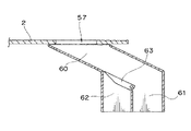
図9および図10は、硬貨選別孔57の略縦断面図である。
【0099】
図9および図10に示されるように、硬貨選別孔57には、硬貨Cの搬送方向に対して、斜め下方に向かうように形成された硬貨回収通路60が接続され、硬貨回収通路60は、汚損レベルが所定レベルを越えた汚損硬貨を回収する汚損硬貨回収通路61と偽造硬貨、外国硬貨などの受け入れ不能硬貨を回収する受け入れ不能硬貨回収通路62とに分岐されており、分岐部には、ゲート63が設けられている。
【0100】
汚損硬貨回収通路61の下端部は、汚損硬貨回収ボックス(図示せず)に接続され、受け入れ不能硬貨回収通路62の下端部は、受け入れ不能硬貨回収ボックス(図示せず)に接続されている。
【0101】
また、ゲート63は、ゲートソレノイド(図示せず)により、汚損硬貨回収通路61と受け入れ不能硬貨回収通路62を分ける壁部の上端部をまわりに揺動可能で、硬貨回収通路60を、図9に示されるように、汚損硬貨回収通路61に連通させ、あるいは、図10に示されるように、受け入れ不能硬貨回収通路62に、選択的に連通可能に構成されている。ゲートソレノイドに駆動信号が出力されない場合には、ゲート63は、図9に示される位置に保持され、硬貨回収通路60は汚損硬貨回収通路61に連通している。
【0102】
図11は、本発明の別の好ましい実施態様にかかる硬貨処理機の入力系、検出系、駆動系、制御系および表示系のブロックダイアグラムである。
【0103】
図11に示されるように、本実施態様にかかる硬貨処理機の入力系は、回収すべき硬貨Cの汚損レベルを設定する汚損レベル設定手段70と、硬貨Cの処理を開始させるスタート手段31を備えており、硬貨処理機の検出系は、光学的に硬貨Cの径、色、表面パターンを検出するとともに、磁気的に硬貨Cの材質を検出するセンサ5と、硬貨を検出する硬貨センサ20と、その上を通過した硬貨Cの枚数を計数するセンサ21を備えている。
【0104】
図11に示されるように、本実施態様にかかる硬貨処理機の駆動系は、回転円板1を回転させる回転円板モータ35と、第一の搬送ベルト8および第二の搬送ベルト9を駆動させる搬送ベルトモータ36と、ドラム55を介して、硬貨選別部材53を間欠的に回転させるパルスモータ72と、ゲート63を揺動させるゲートソレノイド73を備えている。
【0105】
図11に示されるように、本実施態様にかかる硬貨処理機の制御系は、硬貨処理機全体の動作を制御するコントロールユニット40と、制御プログラムならびに処理すべき硬貨Cの径、色および表面パターンに関する光学基準データおよび磁気的な性質に関する磁気基準データならびに硬貨Cの径、色および表面パターンに関する基準汚損レベルデータを記憶するROM41と、各種データを記憶するRAM42を備え、硬貨処理機の表示系は、硬貨処理の結果などを表示するディスプレイパネル44を備えている。
【0106】
ここに、基準汚損レベルデータは、受け入れ可能な硬貨Cの汚損レベルが所定レベルを越えているか否かを判別するものである。硬貨Cが、長期間にわたり、流通されると、磨滅により径がわずかに小さくなったり、色が変化して、表面反射率が低下したり、あるいは、磨滅によって表面の凹凸が少なくなって、表面パターンが変化するため、硬貨Cの径、色、表面パターンについての光学検出データは変化する。したがって、長期間にわたって、流通された硬貨Cの光学基準データは、流通された期間が短い硬貨Cに基づいて生成された光学基準データとは一致しないのが通例であるから、汚損レベルが所定レベルを越えた硬貨Cを判別し、受け入れ不能硬貨Cとは別個に回収するためには、ROM41が、流通期間が短い硬貨Cに基づいて生成された光学基準データに加えて、長期間にわたり、流通された結果、汚損レベルが所定レベルを越えた硬貨Cを判別するための基準汚損レベルデータを記憶していることが必要である。
【0107】
本実施態様においては、汚損レベル設定手段70を操作することによって、オペレータが、回収すべき硬貨の汚損レベルを設定することができるように構成されており、したがって、ROM41には、オペレータが選択し得る汚損レベルに対応した数種の基準汚損レベルデータが金種毎に記憶されている。
【0108】
以上のように構成された本発明の実施態様にかかる硬貨処理機は、以下のようにして、汚損レベルが所定レベルを越えた硬貨Cを検出して、硬貨選別孔57から、硬貨回収通路60を介して、汚損硬貨回収通路61内に導き、汚損硬貨回収ボックス(図示せず)内に回収し、受け入れ不能な硬貨Cを検出して、硬貨選別孔57から、硬貨回収通路60を介して、受け入れ不能硬貨回収通路62内に導き、受け入れ不能硬貨回収ボックス(図示せず)内に回収する。
【0109】
硬貨Cの処理を開始するにあたり、まず、オペレータによって、汚損レベル設定手段70が操作され、次いで、スタート手段31が操作される。
【0110】
オペレータによって、汚損レベル設定手段70が操作され、回収すべき硬貨Cの汚損レベルが設定されると、汚損レベル設定手段70から、汚損レベル設定信号が、コントロールユニット40に出力される。
【0111】
コントロールユニット40は、汚損レベル設定信号を受けると、入力された汚損レベル設定信号にしたがって、回収すべき硬貨Cの汚損レベルをRAM42に書き込む。
【0112】
スタート手段31から、スタート信号が入力されると、コントロールユニット40は、回転円板モータ35および搬送ベルトモータ36に駆動信号を出力して、回転円板1を回転させるとともに、第一の搬送ベルト8および第二の搬送ベルト9を駆動させる。
【0113】
次いで、オペレータによって、硬貨が硬貨投入部(図示せず)に投入される。
【0114】
硬貨投入部(図示せず)から、硬貨処理機に投入された硬貨Cは、硬貨搬送手段(図示せず)により、回転円板1上に送られ、回転円板1の回転によって生じた遠心力により、硬貨選別通路2内に送られる。この際、間隙設定部材22によって、硬貨Cは、一枚づつ、硬貨選別通路2に送られ、硬貨Cの二枚送りが防止される。
【0115】
硬貨選別通路2に送られた硬貨Cは、センサ5により、その径、色、表面パターンおよび磁気的な性質が検出され、センサ5から、検出信号が、コントロールユニット40に出力される。
【0116】
コントロールユニット40は、センサ5から入力された検出信号に基づいて、硬貨Cの径、色、表面パターンに関する光学検出データおよび硬貨Cの磁気的な性質に関する磁気検出データを、ROM41に記憶されている各金種の硬貨Cの光学基準データおよび磁気基準データとを比較する。
【0117】
その結果、硬貨Cの径、色、表面パターンに関する光学検出データおよび硬貨Cの磁気的な性質に関する磁気検出データが、ある金種の硬貨Cの光学基準データおよび磁気基準データと実質的に一致すると認められないときは、センサ5によって検出された硬貨Cは、偽造硬貨や外国硬貨などの受け入れ不能な硬貨Cと考えられるから、コントロールユニット40は、その旨を示す判別データを、RAM42に書き込む。
【0118】
これに対して、硬貨Cの径、色、表面パターンに関する光学検出データおよび硬貨Cの磁気的な性質に関する磁気検出データが、ある金種の硬貨Cの光学基準データおよび磁気基準データと実質的に一致すると認められるときは、コントロールユニット40は、センサ5によって検出された硬貨Cが受け入れ可能な硬貨Cであると判定する。
【0119】
センサ5によって検出された硬貨Cが受け入れ可能な硬貨Cであると判定すると、コントロールユニット40は、さらに、その硬貨Cの金種の基準汚損レベルデータで、汚損レベル設定手段70によって設定された基準汚損レベルデータをROM41から読み出し、硬貨Cの光学検出データと読み出した基準汚損レベルデータとを比較して、硬貨Cの汚損レベルが所定レベルを越えているか否かを判別する。
【0120】
その結果、硬貨Cの汚損レベルが所定レベルを越えていると判定したときは、コントロールユニット40は、その旨を示す判別データを、RAM42に書き込む。
【0121】
これに対して、硬貨Cの汚損レベルが、所定レベル以下であると判定したときは、コントロールユニット40は、RAM42に、何のデータも書き込まない。
【0122】
硬貨Cが、第一の搬送ベルト8および第二の搬送ベルト9によって、さらに、基準ガイドレール3に沿って、硬貨選別通路2内を搬送され、硬貨センサ20によって、硬貨Cが検出されると、硬貨センサ20から、硬貨検出信号が、コントロールユニット40に出力される。
【0123】
コントロールユニット40は、硬貨センサ20から、硬貨検出信号が入力されると、RAM42にアクセスして、その硬貨Cについての判別データが、RAM42に書き込まれているか否かを判定する。
【0124】
その結果、その硬貨Cについての判別データが、RAM42に書き込まれていないと判定したときは、コントロールユニット40は、何の信号も出力しない。
【0125】
したがって、硬貨Cは、硬貨センサ20に検出された後、基準ガイドレール3および基準ガイドレール3のガイド面と滑らかに連なるように配置された硬貨選別部材54の円筒部51に沿って、硬貨選別通路2内を搬送され、図8に示されるように、硬貨Cは、一方の縁部が、硬貨選別部材54の硬貨支持部52の硬貨支持面52aによって支持され、他方の縁部が、硬貨選別通路2に上面によって支持されつつ、硬貨選別通路2内を搬送されて、硬貨選別装置50を通過する。
【0126】
これに対して、RAM42に、硬貨センサ20によって検出された硬貨Cが、受け入れ不能な硬貨Cである旨の判別データが書き込まれているときは、コントロールユニット40は、その硬貨Cが硬貨センサ20を通過するタイミングで、ゲートソレノイド73に駆動信号を出力して、硬貨回収通路60が、受け入れ不能硬貨回収通路62に連通するように、ゲート63を揺動させるとともに、パルスモータ72に駆動信号を出力して、硬貨選別部材54を、水平軸53まわりに、図8において、時計方向に、回転させる。
【0127】
その結果、それまで、硬貨支持面52aによって、硬貨Cの一縁部を支持していた硬貨選別部材54の硬貨支持部52が、硬貨支持位置から回転され、硬貨支持位置に位置していた硬貨支持部52の硬貨支持面52aによって、その一縁部が支持されていた硬貨Cが、それまで硬貨支持位置に保持されていた硬貨支持部52の硬貨支持面52aによる支持を失い、さらに、硬貨選別部材54の回転にともなって、次に、硬貨支持位置に位置すべき硬貨支持部52の硬貨押さえ部52bによって、硬貨Cの上面が、下方に向けて、押圧され、硬貨Cは、硬貨選別孔57内に、強制的に落下させられる。
【0128】
硬貨選別孔57内に落下した硬貨Cは、硬貨回収通路60が、受け入れ不能硬貨回収通路62に連通するように、ゲート63が位置しているため、硬貨回収通路60を介して、受け入れ不能硬貨回収通路62内に導かれ、受け入れ不能硬貨回収ボックス(図示せず)内に回収される。
【0129】
硬貨選別部材54の次に硬貨支持位置に位置すべき硬貨支持部52が硬貨支持位置に達すると、コントロールユニット40は、パルスモータ72に駆動停止信号を出力して、硬貨選別部材54の回転を停止させる。
【0130】
一方、RAM42に、硬貨センサ20によって検出された硬貨Cが、汚損レベルが所定レベルを越えている硬貨Cである旨の判別データが書き込まれているときは、コントロールユニット40は、その硬貨Cが硬貨センサ20を通過するタイミングで、パルスモータ72に駆動信号を出力して、硬貨選別部材54を、水平軸53まわりに、図8において、時計方向に、回転させる。
【0131】
その結果、それまで、硬貨支持面52aによって、硬貨Cの一縁部を支持していた硬貨選別部材54の硬貨支持部52が、硬貨支持位置から回転され、硬貨支持位置に位置していた硬貨支持部52の硬貨支持面52aによって、その一縁部が支持されていた硬貨Cが、それまで硬貨支持位置に保持されていた硬貨支持部52の硬貨支持面52aによる支持を失い、さらに、硬貨選別部材54の回転にともなって、次に、硬貨支持位置に位置すべき硬貨支持部52の硬貨押さえ部52bによって、硬貨Cの上面が、下方に向けて、押圧され、硬貨Cは、硬貨選別孔57内に、強制的に落下させられる。
【0132】
硬貨選別孔57内に落下した硬貨Cは、硬貨回収通路60が、汚損硬貨回収通路61と連通するように、ゲート63が位置しているため、硬貨回収通路60を介して、汚損硬貨回収通路61内に導かれ、汚損硬貨回収ボックス(図示せず)内に回収される。
【0133】
硬貨選別部材54の次に硬貨支持位置に位置すべき硬貨支持部52が硬貨支持位置に達すると、コントロールユニット40は、パルスモータ72に駆動停止信号を出力して、硬貨選別部材54の回転を停止させる。
【0134】
受け入れ可能と判別され、硬貨選別装置50を通過した硬貨Cは、センサ21上を通過して、その枚数が硬貨Cの金種ごとに計数され、あるいは、合計枚数が計数されて、硬貨選別通路2の下流端部に接続された硬貨回収ボックス(図示せず)内に回収される。
【0135】
こうして、硬貨処理機に投入されたすべての硬貨Cが、硬貨回収ボックス、汚損硬貨回収ボックスあるいは受け入れ不能硬貨回収ボックス内に回収されると、硬貨処理機による硬貨Cの処理が完了する。
【0136】
本実施態様によれば、硬貨選別孔57内に落下させて、選別すべき硬貨Cは、まず、その一方の縁部が、硬貨選別部材54の硬貨支持部52の硬貨支持面52aによって支持されるとともに、その他方の縁部が、硬貨選別通路2の上面によって支持され、次いで、パルスモータ72が駆動されて、硬貨選別部材54が、水平軸53まわりに、図8において、時計方向に回転され、その結果、それまで、硬貨支持面52aによって、硬貨Cの一縁部を支持していた硬貨選別部材54の硬貨支持部52が、硬貨支持位置から回転され、硬貨支持位置に位置していた硬貨支持部52の硬貨支持面52aによって、その一縁部が支持されていた硬貨Cが、それまで硬貨支持位置に保持されていた硬貨支持部52の硬貨支持面52aによる支持を失い、さらに、硬貨選別部材54の回転にともなって、次に、硬貨支持位置に位置すべき硬貨支持部52の硬貨押さえ部52bによって、硬貨Cの上面が、下方に向けて、押圧され、硬貨Cは、硬貨選別孔57内に、強制的に落下させられるから、確実に、選別すべき硬貨Cを、硬貨選別孔57内に落下させて、選別することが可能になる。
【0137】
また、本実施態様によれば、硬貨選別部材54を、水平軸53まわりに、図8において、時計方向に回転させることによって、選別すべき硬貨Cを、硬貨選別孔57内に強制的に落下させて、選別するように構成されているから、選別すべき硬貨に先行する硬貨Cや、後続する硬貨Cが、選別すべき硬貨Cに近接して、搬送されていても、選別すべき硬貨Cのみを、確実に、硬貨選別孔57内に落下させて、選別することが可能になり、また、硬貨選別部材54によって、第一の搬送ベルト8および第二の搬送ベルト9が、硬貨選別通路2の幅方向に移動されて、選別すべき硬貨に先行する硬貨Cや、後続する硬貨Cが、硬貨選別孔57内に落下することもなく、したがって、選別すべき硬貨Cのみを、確実に、硬貨選別孔57内に落下させて、選別することが可能になる。
【0138】
さらに、本実施態様によれば、選別すべき硬貨Cは、硬貨選別部材54の次に硬貨支持位置に位置すべき硬貨押さえ部52bによって、硬貨Cの上面が、下方に向けて、押圧され、強制的に、硬貨選別孔57内に落下させられるから、硬貨Cの搬送方向における硬貨選別孔57の長さを十分に長くしなくても、選別すべき硬貨Cを、確実に、硬貨選別孔57内に落下させて、選別することができるから、硬貨の処理効率を向上させるために、硬貨の搬送速度を増大させても、硬貨選別通路2の長さを長くする必要がなく、したがって、硬貨処理機を大幅に小型化することが可能になる。
【0139】
また、本実施態様によれば、硬貨Cの搬送方向に直交する方向における幅が、処理すべき最小径の硬貨Cの径未満になるように、硬貨選別孔57を形成すればよく、下限値に制限がないから、処理すべき硬貨Cの径に制限が加えられることがなく、金種によって径が大きく異なる硬貨Cを、所望のように、選別することが可能になる。
【0140】
本発明は、以上の実施態様に限定されることなく、特許請求の範囲に記載された発明の範囲内で種々の変更が可能であり、それらも本発明の範囲内に包含されるものであることはいうまでもない。
【0141】
たとえば、図1ないし図7に示された実施態様においては、包装すべき硬貨C以外の硬貨Cを、硬貨選別孔11内に強制的に落下させて、選別するように構成され、図8ないし図11に示された実施態様においては、汚損レベルが所定レベルを越えている硬貨Cおよび偽造硬貨や外国硬貨などの受け入れ不能な硬貨Cを、硬貨選別孔57内に強制的に落下させて、選別するように構成されているが、特定の金種の硬貨Cを、硬貨選別孔11、57内に強制的に落下させて、選別するように構成することもでき、選別すべき硬貨Cは、任意に選択することができる。
【0142】
また、図1ないし図7に示された実施態様においては、硬貨処理機は、オペレータによって指定された金種の硬貨Cを包装可能に構成されているが、硬貨処理機が包装機能を有していることは必ずしも必要でない。
【0143】
さらに、図1ないし図7に示された実施態様においては、ロータリーソレノイド13によって、アーム16、アーム16の先端部16aに形成されたギアおよびこれに噛み合う係合部12bのギアを介して、硬貨選別部材12が回転されるように構成されているが、ロータリーソレノイド13によって、アーム16、アーム16の先端部16aに形成されたギアおよびこれに噛み合う係合部12bのギアを介して、硬貨選別部材12が回転されるように構成することは必ずしも必要でなく、硬貨選別部材12を回転させる駆動機構は、任意に選択することができる。
【0144】
また、図8ないし図11に示された実施態様においては、パルスモータ72によって、ドラム55、ドラム55の周囲に形成されたギアおよび係合部材の周囲に形成されたギアを介して、硬貨選別部材54が回転されるように構成されているが、パルスモータ72によって、ドラム55、ドラム55の周囲に形成されたギアおよび係合部材の周囲に形成されたギアを介して、硬貨選別部材54が回転されるように構成することは必ずしも必要でなく、硬貨選別部材54を回転させる駆動機構は、任意に選択することができる。
【0145】
さらに、図8ないし図11に示された実施態様においては、硬貨選別部材54の円筒部51には、放射状に延びた6つの硬貨支持部52が形成されているが、硬貨選別部材54の円筒部51に、放射状に延びた6つの硬貨支持部52を形成することは必ずしも必要でなく、硬貨支持部52の数は任意に選択することができる。
【0146】
また、図1ないし図7に示された実施態様においては、硬貨選別部材12は、水平軸12aまわりに、回転され、硬貨選別部材12の硬貨支持部材12cが、下方に揺動して、硬貨Cの一縁部の支持を解除するように構成され、図8ないし図11に示された実施態様においては、硬貨選別部材54は、水平軸53まわりに、回転され、それまで、硬貨Cの一縁部を支持していた硬貨支持部52が、下方に揺動して、硬貨Cの一縁部の支持を解除するように構成されているが、硬貨選別部材を、硬貨Cの一縁部を支持する硬貨支持位置と、硬貨選別通路2から水平方向に退避した退避位置との間で、水平方向に移動可能に設けるとともに、硬貨Cを、下方に向けて、押圧する硬貨押さえ部材を、硬貨選別部材とは別体に設け、リンク機構などを用いて、硬貨選別部材が、硬貨支持位置から退避位置に移動するのに同期して、硬貨押さえ部材が、硬貨を、下方に向けて、押圧するように移動させて、選別すべき硬貨Cを、硬貨選別孔内に、強制的に落下させるように構成することもできる。
【0147】
さらに、図8ないし図11に示された実施態様においては、硬貨処理機は、汚損レベル設定手段70を備え、汚損レベル設定手段70によって、選別して、回収すべき硬貨Cの汚損レベルを、任意に設定手段得るように構成されているが、硬貨処理機が、汚損レベル設定手段70を備えていることは、必ずしも必要でない。
【0148】
また、図8ないし図11に示された実施態様においては、硬貨処理機の硬貨回収通路60は、汚損硬貨回収通路61と受け入れ不能硬貨回収通路62とに分岐され、ゲート63によって、汚損レベルが所定レベルを越えた硬貨Cは、硬貨回収通路60から汚損硬貨回収通路61に導かれ、受け入れ不能硬貨は、硬貨回収通路60から受け入れ不能硬貨回収通路62に導かれて、別個に回収されるように構成されているが、硬貨処理機の硬貨回収通路60を、汚損硬貨回収通路61と受け入れ不能硬貨回収通路62とに分岐させ、汚損レベルが所定レベルを越えた硬貨Cを、硬貨回収通路60から汚損硬貨回収通路61に導き、受け入れ不能硬貨を、硬貨回収通路60から受け入れ不能硬貨回収通路62に導いて、別個に回収することは必ずしも必要でなく、汚損レベルが所定レベルを越えた硬貨Cおよび受け入れ不能硬貨を、硬貨回収通路60を介して、同じ回収ボックスに導いて、回収し、その後に、分別するようにしてもよい。
【0149】
さらに、図1ないし図7に示された実施態様においては、硬貨選別装置10の下流側に設けられたセンサ21を通過した包装すべき硬貨Cの枚数を計数して、所定枚数の包装すべき硬貨Cが硬貨集積部内に送られたと判定すると、センサ21の下流側に設けられたストッパ(図示せず)を、硬貨選別通路2内に突出させて、後続する硬貨Cが、硬貨集積部内に送られることを阻止するように構成されているが、ストッパを、センサ5と硬貨選別装置10との間に設けて、所定枚数の包装すべき硬貨Cが、センサ5によって検出されるまでは、センサ5を通過したすべての硬貨Cを硬貨選別装置10に導き、包装すべき硬貨Cのみを硬貨選別装置10を通過させ、包装すべき硬貨C以外の硬貨Cを、硬貨選別孔11内に強制的に落下させて、硬貨Cを選別するように構成することもできる。
【0150】
また、図8ないし図11に示された実施態様においては、受け入れ可能を判別された硬貨Cを、硬貨選別装置10およびセンサ21を通過させ、センサ21を通過した受け入れ可能な硬貨Cの枚数を金種ごとに計数し、あるいは、センサ21を通過した受け入れ可能な硬貨Cの合計枚数を計数するように構成されているが、ストッパを、硬貨選別装置50の上流側あるいは下流側に設け、センサ5によって検出された受け入れ可能な硬貨Cの金種ごとの枚数あるいは合計枚数が所定の枚数に達するまで、センサ5を通過したすべての硬貨Cを硬貨選別装置50に導き、受け入れ可能な硬貨Cのみを硬貨選別装置10を通過させ、受け入れ可能でないと判別された硬貨Cを、硬貨選別孔57内に強制的に落下させて、硬貨Cを選別するように構成することもできる。
【0151】
【発明の効果】
本発明によれば、装置を大型化させることなく、硬貨選別通路に供給された硬貨のうちから、所定の硬貨を、確実に、硬貨選別通路に形成された硬貨選別孔内に落下させて、選別することができる硬貨処理機を提供することが可能になる。
【図面の簡単な説明】
【図1】図1は、本発明の好ましい実施態様にかかる硬貨処理機の硬貨選別通路の略平面図である。
【図2】図2は、本発明の好ましい実施態様にかかる硬貨処理機の硬貨選別通路の略左側面図である。
【図3】図3は、本発明の好ましい実施態様にかかる硬貨処理機の硬貨選別装置の略平面図である。
【図4】図4は、本発明の好ましい実施態様にかかる硬貨処理機の硬貨選別装置の略側面図である。
【図5】図5は、硬貨選別部材が退避位置に位置しているときの硬貨選別装置の略側面図である。
【図6】図6は、第一の搬送ベルトおよび第二の搬送ベルトを取り去った硬貨処理機の略平面図である。
【図7】図7は、本発明の好ましい実施態様にかかる硬貨処理機の入力系、検出系、駆動系、制御系および出力系のブロックダイアグラムである。
【図8】図8は、本発明の別の好ましい実施態様にかかる硬貨処理機の硬貨選別装置の略側面図である。
【図9】図9は、硬貨選別孔の略縦断面図である。
【図10】図10は、硬貨回収通路が、受け入れ不能硬貨回収通路に連通しているときの硬貨選別孔の略縦断面図である。
【図11】図11は、本発明の別の好ましい実施態様にかかる硬貨処理機の入力系、検出系、駆動系、制御系および表示系のブロックダイアグラムである。
【符号の説明】
1 回転円板
2 硬貨選別通路
3 基準ガイドレール
4 ガイドレール
5 センサ
6a、6b プーリ
7 プーリ
8 第一の搬送ベルト
9 第二の搬送ベルト
10 硬貨選別装置
11 硬貨選別孔
12 硬貨選別部材
12a 水平軸
12b 硬貨選別部材の係合部
12c 硬貨支持部材
12d ギア
12e 硬貨押さえ部材
12f 硬貨選別部材の硬貨支持部
13 ロータリーソレノイド
13a ロータリーソレノイドの出力軸
16 アーム
16a アームの先端部
16b ギア
20 硬貨センサ
21 センサ
22 間隙設定部材
23 押さえローラ
25 基準ガイドレールの斜壁部分
30 金種設定手段
31 スタート手段
35 回転円板モータ
36 搬送ベルトモータ
40 コントロールユニット
41 ROM
42 RAM
44 ディスプレイパネル
50 硬貨選別装置
51 硬貨選別部材の円筒部
52 硬貨選別部材の硬貨支持部
52a 硬貨支持面
52b 硬貨押さえ部
53 水平軸
54 硬貨選別部材
55 ドラム
55a ギア
56 パルスモータの出力軸
57 硬貨選別孔
60 硬貨回収通路
61 汚損硬貨回収通路
62 受け入れ不能硬貨回収通路
63 ゲート
70 汚損レベル設定手段
72 パルスモータ
73 ゲートソレノイド[0001]
BACKGROUND OF THE INVENTION
The present invention relates to a coin processor, and more specifically, a predetermined coin is reliably formed in a coin sorting passage from among the coins supplied to the coin sorting passage without increasing the size of the apparatus. The present invention relates to a coin processor that can be dropped and sorted in a coin sorting hole.
[0002]
[Prior art]
A plurality of coin sorting holes are formed in the coin sorting passage in ascending order of diameter, and among the coins of denominations to be processed, the coins are dropped in order from the coin with the smallest diameter to sort the coins. A coin processing machine configured as described above is known.
[0003]
However, in the coin processing machine configured as described above, it is indispensable to form coin sorting holes having the same number as the denomination of the coin to be processed in the coin sorting passage. There was a problem that the coin processing machine was increased in size.
[0004]
Therefore, U.S. Pat. No. 4,681,204 discloses that at least one coin sorting hole is formed in the coin sorting passage, and a coin sorting member protruding into the coin sorting passage is provided, upstream of the coin sorting hole. When the sensor provided in the sensor detects a predetermined coin, the coin sorting member is moved in the width direction of the coin sorting passage to protrude into the coin sorting passage, and the predetermined coin is selectively It proposes a coin processor configured to drop into a sorting hole for sorting.
[0005]
According to this coin processor, there is an advantage that only a predetermined coin can be selectively dropped into the coin sorting hole and sorted without increasing the size of the coin processor.
[0006]
[Problems to be solved by the invention]
However, in this coin processing machine, the coin sorting member is moved in the width direction of the coin sorting passage, protruded into the coin sorting passage, and a predetermined coin is selectively dropped into the coin sorting hole. Therefore, when the distance between the coin to be sorted and the coin preceding the coin to be sorted or the succeeding coin is small when the coin is transported, the coin is sorted by the coin sorting member. Together with the coins to be sorted, the coins preceding and following the coins to be sorted are moved in the width direction of the coin sorting passage, fall into the coin sorting holes, and with the coins to be sorted by the coin sorting member Since the conveyor belt is also moved in the width direction of the coin sorting passage, the coin preceding the coin to be sorted and the succeeding coin are also moved in the width direction of the coin sorting path with the movement of the conveyor belt. Is in, may fall into the coin sorting opening, there is a case where, as desired, it is impossible to sort coins.
[0007]
Furthermore, in this coin processor, when the coin sorting member is not driven, the coin having the smallest diameter to be processed passes through the coin sorting hole without falling into the coin sorting hole, and the coin sorting member is In order to ensure that the largest diameter coin will fall into the coin sorting hole when driven, the width of the coin sorting hole in the direction perpendicular to the coin transport direction is the diameter of the smallest coin to be processed. It is indispensable to form it so that it is less than 1/2 the diameter of the maximum diameter coin to be processed, and there is a problem that the diameter of the coin to be processed is limited.
[0008]
In addition, since the coin moved in the width direction of the coin sorting passage by the coin sorting member is configured to fall into the coin sorting hole by free fall, the coin to be sorted is surely selected. When the coin sorting hole is required to be formed so that the length of the coin in the conveying direction is sufficiently long so as to fall into the hole, and when a plurality of coin sorting holes are formed in the coin sorting passage, In order to increase the length of the coin sorting passage and improve the processing efficiency of coins, it is necessary to further increase the length of the coin sorting passage when the coin transport speed is increased. There was also a problem of increasing the size.
[0009]
Therefore, the present invention reliably drops a predetermined coin from the coins supplied to the coin sorting passage into the coin sorting hole formed in the coin sorting passage without increasing the size of the device, An object of the present invention is to provide a coin processing machine capable of sorting.
[0010]
[Means for Solving the Problems]
An object of the present invention is to receive coins inserted into a coin processor, and guide the coins by a rotating disk that feeds the coins one by one to a coin sorting passage and its inner wall by centrifugal force generated by the rotation. In a coin processing machine comprising a reference guide rail, a transport belt means for transporting while holding a coin between the surfaces of the coin sorting passage, and a sensor for detecting optical and magnetic properties of the coin, Further, along the inner wall of the reference guide rail, a coin sorting hole formed in the coin sorting passage on the downstream side of the sensor, Provided outside the reference guide rail side of the coin sorting passage and rotatable only in the coin sorting hole near the reference guide rail about a substantially horizontal axis parallel to the longitudinal axis of the coin sorting passage. A coin sorting member, and the coin sorting member is transported in the coin sorting path by the transport belt means. only At least one coin support portion having a coin support surface capable of supporting Formed integrally with the at least one coin support, And at least one coin holding part capable of pressing a coin, Of the at least one coin support The coin support surface is one edge of a coin that is conveyed in the coin sorting passage only Between the coin support position capable of supporting the coin and the retreat position where the coin support surface is retracted from the coin support position and cannot support the coin. The coin sorting member is rotated about the horizontal axis to move the at least one coin support, and In synchronization with the rotation of the coin support portion to the retracted position, At least one Move the coin holding part so that the coin is pushed downward. Possible A coin sorting member driving means; and a control means for driving the coin sorting member driving means based on a detection signal of the sensor; The control means drives the coin sorting member driving means based on the detection signal of the sensor, so that the at least one coin support portion of the coin sorting member The coins supported by the coin support surface are forcibly dropped into the coin sorting hole for sorting. Possible This is achieved by a coin processor characterized by being configured.
[0011]
According to the present invention, the coin processor has a coin sorting hole formed in a coin sorting passage on the downstream side of the sensor along the inner wall of the reference guide rail, Provided outside the reference guide rail side of the coin sorting passage and rotatable only in the coin sorting hole near the reference guide rail around a substantially horizontal axis parallel to the longitudinal axis of the coin sorting passage. A coin sorting member, and the coin sorting member is conveyed in the coin sorting passage by the conveying belt means. only At least one coin support portion having a coin support surface capable of supporting Formed integrally with at least one coin support, And at least one coin holding part capable of pressing a coin, Of at least one coin support Coin support surface is one edge of the coin that is transported in the coin sorting passage only Between the coin support position that can support the coin and the retreat position where the coin support surface is retracted from the coin support position and cannot support the coin The coin sorting member can be rotated about a horizontal axis to move at least one coin support, and In synchronization with the rotation of the coin support to the retracted position, At least one Move the coin holding part so that the coin is pushed downward. Possible Since it comprises a coin sorting member driving means and a control means for driving the coin sorting member driving means based on the detection signal of the sensor, it is dropped into the coin sorting hole and sorted based on the detection signal of the sensor. When detecting the coin that should be, the control means, the coin support surface is retracted from the coin support position, to the retract position that can not support the coin, At least one Move the coin support part, release the coin support by the coin support surface of the coin support part, and push the coin holding part downward with the coin holding down in synchronization with the movement of the coin support surface to the retracted position. The coin was supported by the coin support surface by driving the coin sorting member driving means so as to move The Forcibly dropped into the coin sorting hole It becomes possible Thus, the coins to be sorted can be reliably dropped and dropped into the coin sorting hole.
[0012]
Further, according to the present invention, since the coin to be sorted can be forcibly dropped into the coin sorting hole, the coin preceding the coin to be sorted and the succeeding coin are close to the coin to be sorted. Even if it is being transported, only the coins to be sorted can be surely dropped into the coin sorting hole and sorted, and the conveyor belt means can sort the coins by the coin sorting member. The coin that is moved in the width direction of the passage and precedes the coin to be sorted and the following coin does not fall into the coin sorting hole, so that only the coin to be sorted is surely selected. It is possible to drop it in and sort it out.
[0013]
Further, according to the present invention, since the coins to be sorted can be forcibly dropped into the coin sorting hole, the sorting is performed without sufficiently increasing the length of the coin sorting hole in the coin conveying direction. It is possible to reliably drop the coins to be dropped into the coin sorting hole, and therefore, in order to improve the processing efficiency of the coins, the length of the coin sorting passage can be increased even if the conveying speed of the coins is increased. Since it is not necessary to increase the length, the coin processor can be greatly reduced in size.
[0015]
in addition, According to the present invention, when the coin to be sorted is detected by dropping into the coin sorting hole based on the detection signal of the sensor, the coin sorting member is rotated about the substantially horizontal axis, Promptly, Moving the coin support portion to the retracted position to release the coin support by the coin support surface of the coin, and at least one coin support portion; Integrally With the coin holding part formed, the coin that is no longer supported by the coin support surface is directed downward, What , Forcibly falling into the coin sorting hole Can be Thus, the coins to be sorted can be reliably dropped and dropped into the coin sorting hole.
[0016]
In a further preferred embodiment of the present invention, The coin sorting member includes a single coin support part and a coin holding part, When the coin support part has a side wall part substantially orthogonal to the coin support surface, and the coin support part of the coin sorting member is located at the coin support position, the side wall of the coin support part. The coin is smoothly connected to the inner wall of the reference guide rail, and the distance between the side of the coin sorting passage on the coin sorting passage side and the side wall of the coin supporting portion is the smallest diameter coin to be processed. The coin sorting hole is formed so as to be less than the diameter of the coin, and the coin sorting member is provided.
[0017]
According to a further preferred embodiment of the present invention, the coin support portion has a side wall portion that is substantially orthogonal to the coin support surface, and the coin support portion of the coin sorting member is located at the coin support position. The side wall portion of the support portion is smoothly connected to the inner wall of the reference guide rail. Since the coin sorting hole is formed and the coin sorting member is provided so as to be less than the lower limit, the lower limit of the width of the coin sorting hole in the direction orthogonal to the coin conveying direction is not limited. No limitation is imposed on the diameter of the coins, and it becomes possible to sort out coins whose diameters vary greatly depending on the denomination as desired.
[0018]
In a further preferred embodiment of the present invention, the coin sorting member driving means is constituted by a rotary solenoid.
[0019]
According to a further preferred embodiment of the present invention, since the coin sorting member driving means is constituted by a rotary solenoid, the coin sorting member can be quickly rotated around a substantially horizontal axis, and therefore the coin support The coin is not supported by the coin support surface by the coin holding part integrally attached to the coin support part above the coin support surface. It is possible to push the coins downward and forcefully drop them into the coin sorting holes for sorting.
[0020]
In a further preferred embodiment of the present invention, further, on the output shaft of the rotary solenoid, An arm with one end fixed and the other end Has a fan-shaped cross section A gear was formed with the eggplant Arm comprising an coin sorting machine Element Is provided with an engaging portion having a fan-shaped side cross-section in which a gear is formed, and the gear formed in the engaging portion is the arm of the arm. The other end Engage with the gear formed on the driving force of the rotary solenoid But Coin sorting Element It is configured to be able to communicate with.
[0021]
Of the present invention another In a preferred embodiment, the coin sorting member includes a cylindrical portion and a plurality of the cylindrical portion formed to extend radially. Protrusion The plurality of Protrusion Respectively It is comprised by the side surface located in an upstream with respect to the direction where the said coin selection member rotates. Coin support And the side surface located downstream Coin holding part And when one coin support part of the plurality of coin support parts is located at the coin support position, the one coin support part is moved into the coin sorting passage by the conveyor belt means. A coin support surface capable of supporting only one edge of the coin being conveyed is formed, and the one coin support portion is configured in synchronization with the rotation of the one coin support portion to the retracted position. The coin presser that pushes the upper surface of the coin, which is supported by the one coin supporter that moves to the retracted position, downward, on the coin presser of the protrusion adjacent to the upstream side of the protrusion. Is supposed to compose .
[0022]
Of the present invention another According to a preferred embodiment, the coin sorting member includes a cylindrical portion and a plurality of the cylindrical sorting portions that extend radially. Protrusion With multiple Protrusion Respectively The coin sorting member is constituted by the side surface located on the upstream side with respect to the direction in which the coin sorting member rotates. Coin support And the side surface located downstream Coin holding part A coin that is transported in the coin sorting path by the transport belt means when one coin support portion of the plurality of coin support portions is located at the coin support position. A coin support surface capable of supporting only one edge is formed, and is adjacent to the upstream side of the protruding portion constituting one coin support portion in synchronization with the rotation of one coin support portion to the retracted position. The coin holding part of the protruding part constitutes a coin holding part that pushes the upper surface of the coin supported by one coin supporting part moving to the retracted position downward. From the detection signal of the sensor, when dropping the coin into the coin sorting hole and detecting the coin to be sorted, by rotating the coin sorting member about the substantially horizontal axis, Promptly, one While moving the coin support part to the retracted position, releasing the coin support by the coin support surface of the coin support part, Coin holding part of the protrusion part adjacent to the upstream of the protrusion part which comprises one coin support part By Of one coin support Coins that are no longer supported by the coin support surface The , Push downwards What Since it can be forcibly dropped into the coin sorting hole, the coins to be sorted can be reliably dropped into the coin sorting hole and sorted.
[0025]
In a further preferred embodiment of the present invention, when the coin support portion of the coin sorting member is located at the coin support position, the peripheral surface of the cylindrical portion of the coin sorting member is the reference guide rail. The coin sorting hole is formed so that the interval between the coin sorting hole and the side of the coin sorting passage is less than the diameter of the smallest coin to be processed, A coin sorting member is provided.
[0026]
According to a further preferred embodiment of the present invention, when the coin support portion of the coin sorting member is located at the coin support position, the peripheral surface of the cylindrical portion of the coin sorting member is smoothly on the inner wall of the reference guide rail. Since the coin sorting hole is formed and the coin sorting member is provided so that the distance between the coin sorting hole and the side of the coin sorting passage is less than the diameter of the smallest coin to be processed, The lower limit of the width of the coin sorting hole in the direction orthogonal to the coin transport direction is not limited, and therefore, the diameter of the coin to be processed is not limited, and a coin having a large diameter depending on the denomination is desired. So that it becomes possible to sort.
[0027]
In a further preferred embodiment of the present invention, the coin sorting member driving means is constituted by a pulse motor.
[0028]
In a further preferred aspect of the present invention, a drum having a gear formed on its peripheral surface is fixed to the output shaft of the pulse motor, and a cylindrical engagement having a gear formed on the peripheral surface of the coin sorting member. A joint member is integrally attached, and the gear formed on the peripheral surface of the engaging member engages with the gear formed on the peripheral surface of the drum, and the driving force of the pulse motor is The coin sorting member can be transmitted.
[0029]
In a further preferred embodiment of the present invention, the pulse motor is configured to be able to rotate the coin sorting member so that the plurality of coin support portions are sequentially positioned at the coin support position.
[0030]
According to a further preferred embodiment of the present invention, since the pulse motor is configured to be able to rotate the coin sorting member so that the plurality of coin support portions are sequentially positioned at the coin support position, the coin to be sorted However, even if it is conveyed one after another, it can be surely dropped and sorted in the coin sorting hole.
[0031]
DETAILED DESCRIPTION OF THE INVENTION
Hereinafter, preferred embodiments of the present invention will be described in detail with reference to the accompanying drawings.
[0032]
FIG. 1 is a schematic plan view of a coin sorting path of a coin processor according to a preferred embodiment of the present invention, and FIG. 2 is a schematic left side view of FIG.
[0033]
In this embodiment, the coin processing machine is configured to be able to wrap coins of denominations designated by the operator.
[0034]
As shown in FIG. 1, the coin processing machine according to the present embodiment is a
[0035]
The
[0036]
Further, the
[0037]
FIG. 3 is a schematic plan view of a coin sorting device of a coin processor according to a preferred embodiment of the present invention.
[0038]
As shown in FIG. 3, the
[0039]
FIG. 4 is a schematic side view of the
[0040]
As shown in FIG. 4, the distal end portion 16 a of the
[0041]
As shown in FIG. 4, the
[0042]
The
[0043]
In this embodiment, when the
[0044]
As shown in FIG. 4, a
[0045]
FIG. 5 is a schematic side view of the
[0046]
As shown in FIG. 5, when the
[0047]
As a result, the rotational force of the
[0048]
Therefore, the
[0049]
As shown in FIG. 1 and FIG. 3, the
[0050]
The pulley 6b on which the
[0051]
In FIG. 1,
[0052]
FIG. 6 is a schematic plan view of the coin processing machine with the
[0053]
As shown in FIG. 6, the
[0054]
Although not shown in the figure, the downstream end of the
[0055]
FIG. 7 is a block diagram of an input system, a detection system, a drive system, a control system, and a display system of a coin processor according to a preferred embodiment of the present invention.
[0056]
As shown in FIG. 7, the input system of the coin processing machine according to the present embodiment includes a denomination setting unit 30 for inputting the denomination of the coin C to be packaged, and a start unit 31 for starting the processing of the coin C. The coin processor has a detection system that optically detects the diameter, color, and surface pattern of the coin C, magnetically detects the material of the coin C, a
[0057]
As shown in FIG. 7, the drive system of the coin processor according to the present embodiment drives the rotary disk motor 35 that rotates the
[0058]
As shown in FIG. 7, the control system of the coin processor according to the present embodiment includes a control unit 40 that controls the operation of the entire coin processor, a control program, and the diameter, color, and surface pattern of the coin C to be processed. A ROM 41 for storing optical reference data relating to magnetic properties and magnetic reference data relating to magnetic properties, and a RAM 42 for storing various data. The display system of the coin processor includes a display panel 44 for displaying the results of coin processing and the like. Yes.
[0059]
The coin processing machine according to the embodiment of the present invention configured as described above selects and collects coins C other than the coins C of the designated denomination as follows, and designates the designated gold. Wrap seed coins C.
[0060]
In starting the processing of the coin C, first, the operator operates the denomination setting unit 30 to set the denomination of the coin C to be packaged, and then operates the start unit 31.
[0061]
When the denomination of the coin C to be wrapped is set by the operator, a denomination setting signal is output from the denomination setting means 30 to the control unit 40.
[0062]
When a denomination setting signal is input from the denomination setting means 30, the control unit 40, based on the input denomination setting signal, reads from the ROM 41 the optics related to the diameter, color, and surface pattern of the coins C to be wrapped. The reference data and magnetic reference data relating to magnetic properties are read out and stored in the RAM 42.
[0063]
When a start signal is input from the start means 31, the control unit 40 outputs drive signals to the rotating disk motor 35 and the conveying belt motor 36 to rotate the
[0064]
Next, the operator inserts coins into a coin insertion unit (not shown).
[0065]
Coins C input from a coin input unit (not shown) into a coin processor are sent onto the
[0066]
The diameter, color, surface pattern and magnetic property of the coin C sent to the
[0067]
Based on the detection signal input from the
[0068]
As a result, it is recognized that the optical detection data regarding the diameter, color, and surface pattern of the coin C and the optical reference data substantially match, and the magnetic detection data and the magnetic reference data regarding the magnetic properties of the coin C are substantially the same. When it is recognized that the coins are coincident with each other, the control unit 40 determines that the coin C is the coin C of the denomination to be wrapped set by the denomination setting unit 30, and indicates data indicating that. Write to RAM42.
[0069]
On the other hand, when it is determined that the coin C is not the coin C of the denomination set by the denomination setting unit 30, the control unit 40 writes data indicating that in the RAM 42.
[0070]
When the coin C is further conveyed by the
[0071]
When a coin detection signal is input from the
[0072]
Therefore, the coin C of the denomination to be packaged is detected by the
[0073]
On the other hand, based on the data stored in the RAM 42, the coin C is a coin other than the denomination coin C to be wrapped, that is, a genuine coin C of a denomination other than the denomination coin C to be wrapped. Alternatively, when it is determined that the coin C is unacceptable, such as a fake coin or a foreign coin, the control unit 40 outputs a drive signal to the
[0074]
When a drive signal is output from the control unit 40 to the
[0075]
As a result, the
[0076]
Therefore, after the
[0077]
Thus, in this embodiment, the
[0078]
When a predetermined time elapses after driving the
[0079]
As a result, the
[0080]
On the other hand, the coin C to be packaged that has passed through the
[0081]
Each time the
[0082]
A predetermined number of coins C that have been sent to the coin accumulating unit are sent to a coin wrapping unit (not shown), and a wrapping paper is wound around them by a plurality of wrapping rollers. A role is generated.
[0083]
On the other hand, the control unit 40 outputs a drive signal to the
[0084]
In this way, all the coins to be wrapped are sent to the coin accumulating unit by a predetermined number, and are packed by the coin packaging unit, and all the coins C other than the denomination coins to be wrapped are sorted by the
[0085]
According to this embodiment, the coin C to be sorted by being dropped into the
[0086]
Moreover, according to this embodiment, the
[0087]
Furthermore, according to this embodiment, the coin C to be sorted is pushed downward by the
[0088]
Moreover, according to the present embodiment, the
[0089]
FIG. 8 is a schematic side view of a coin sorting device of a coin processor according to another preferred embodiment of the present invention.
[0090]
The coin processor according to the present embodiment sorts out unacceptable coins C such as counterfeit coins, foreign coins, etc. and coins C that have been soiled beyond a predetermined level from among the coins C put into the coin processor. And are configured to be collected separately.
[0091]
As shown in FIG. 8, a
[0092]
Although not shown in FIG. 8, a cylindrical engaging member having a gear is integrally attached around the
[0093]
The
[0094]
Therefore, the rotational force of the pulse motor is transmitted to the
[0095]
As shown in FIG. 8, each
[0096]
As shown in FIG. 8, the
[0097]
When the
[0098]
9 and 10 are schematic longitudinal sectional views of the
[0099]
As shown in FIG. 9 and FIG. 10, the
[0100]
The lower end of the dirty
[0101]
Further, the
[0102]
FIG. 11 is a block diagram of an input system, a detection system, a drive system, a control system, and a display system of a coin processor according to another preferred embodiment of the present invention.
[0103]
As shown in FIG. 11, the input system of the coin processor according to the present embodiment includes a contamination level setting unit 70 that sets a contamination level of the coin C to be collected, and a start unit 31 that starts the processing of the coin C. The coin processor has a detection system that optically detects the diameter, color, and surface pattern of the coin C and magnetically detects the material of the coin C, and a
[0104]
As shown in FIG. 11, the drive system of the coin processor according to the present embodiment drives the rotary disk motor 35 that rotates the
[0105]
As shown in FIG. 11, the control system of the coin processor according to this embodiment includes a control unit 40 that controls the operation of the entire coin processor, a control program, and the diameter, color, and surface pattern of the coin C to be processed. A ROM 41 for storing optical reference data for magnetic properties, magnetic reference data for magnetic properties, and reference contamination level data for the diameter, color and surface pattern of the coin C, and a RAM 42 for storing various data. A display panel 44 is provided for displaying the result of coin processing.
[0106]
Here, the reference fouling level data is used to determine whether or not the fouling level of the accepted coin C exceeds a predetermined level. If the coin C is circulated for a long period of time, the diameter slightly decreases due to abrasion, the color changes, the surface reflectance decreases, or the surface unevenness decreases due to abrasion. Since the pattern changes, the optical detection data for the diameter, color, and surface pattern of the coin C changes. Therefore, since the optical reference data of the coins C that have been distributed over a long period of time typically does not match the optical reference data generated based on the coins C that have been distributed for a short time, the contamination level is a predetermined level. In order to discriminate the coins C exceeding the limit and collect them separately from the unacceptable coins C, the ROM 41 distributes over a long period in addition to the optical reference data generated based on the coins C with a short distribution period. As a result, it is necessary to store reference fouling level data for discriminating coins C whose fouling level exceeds a predetermined level.
[0107]
In this embodiment, the operator can set the contamination level of the coins to be collected by operating the contamination level setting means 70. Therefore, the operator selects the ROM 41 in the ROM 41. Several kinds of reference pollution level data corresponding to the obtained pollution level are stored for each denomination.
[0108]
The coin processing machine according to the embodiment of the present invention configured as described above detects a coin C having a fouling level exceeding a predetermined level as described below, and receives a
[0109]
In starting the processing of the coin C, first, the contamination level setting means 70 is operated by the operator, and then the start means 31 is operated.
[0110]
When the operator operates the contamination level setting means 70 and sets the contamination level of the coin C to be collected, a contamination level setting signal is output from the contamination level setting means 70 to the control unit 40.
[0111]
When receiving the contamination level setting signal, the control unit 40 writes the contamination level of the coin C to be collected in the RAM 42 in accordance with the input contamination level setting signal.
[0112]
When a start signal is input from the start means 31, the control unit 40 outputs drive signals to the rotating disk motor 35 and the conveying belt motor 36 to rotate the
[0113]
Next, the operator inserts coins into a coin insertion unit (not shown).
[0114]
Coins C input from a coin input unit (not shown) into a coin processor are sent onto the
[0115]
The diameter, color, surface pattern and magnetic property of the coin C sent to the
[0116]
Based on the detection signal input from the
[0117]
As a result, the optical detection data regarding the diameter, color, and surface pattern of the coin C and the magnetic detection data regarding the magnetic property of the coin C substantially coincide with the optical reference data and magnetic reference data of the coin C of a denomination. When it is not recognized, the coin C detected by the
[0118]
On the other hand, the optical detection data regarding the diameter, color, and surface pattern of the coin C and the magnetic detection data regarding the magnetic property of the coin C are substantially the same as the optical reference data and magnetic reference data of the coin C of a denomination. When it is recognized that they match, the control unit 40 determines that the coin C detected by the
[0119]
If it is determined that the coin C detected by the
[0120]
As a result, when it is determined that the contamination level of the coin C exceeds a predetermined level, the control unit 40 writes determination data indicating that in the RAM 42.
[0121]
In contrast, when it is determined that the contamination level of the coin C is equal to or lower than the predetermined level, the control unit 40 does not write any data in the RAM 42.
[0122]
When the coin C is further conveyed by the
[0123]
When a coin detection signal is input from the
[0124]
As a result, when it is determined that the discrimination data for the coin C is not written in the RAM 42, the control unit 40 does not output any signal.
[0125]
Therefore, after the coin C is detected by the
[0126]
On the other hand, when the discrimination data indicating that the coin C detected by the
[0127]
As a result, until then, the
[0128]
Since the
[0129]
When the
[0130]
On the other hand, when the discrimination data indicating that the coin C detected by the
[0131]
As a result, until then, the
[0132]
The coin C that has fallen into the
[0133]
When the
[0134]
The coin C that has been determined to be acceptable and passed through the
[0135]
Thus, when all the coins C put into the coin processor are collected in the coin collection box, the damaged coin collection box or the unacceptable coin collection box, the processing of the coin C by the coin processor is completed.
[0136]
According to this embodiment, the coin C to be sorted by dropping into the
[0137]
Moreover, according to this embodiment, the
[0138]
Furthermore, according to the present embodiment, the coin C to be sorted is pressed downward by the
[0139]
Moreover, according to the present embodiment, the
[0140]
The present invention is not limited to the above-described embodiments, and various modifications are possible within the scope of the invention described in the claims, and these are also included in the scope of the present invention. Needless to say.
[0141]
For example, the embodiment shown in FIGS. 1 to 7 is configured to forcibly drop coins C other than the coins C to be packaged into the
[0142]
Further, in the embodiment shown in FIGS. 1 to 7, the coin processing machine is configured to be able to wrap the coin C of the denomination designated by the operator, but the coin processing machine has a packaging function. It is not always necessary.
[0143]
Further, in the embodiment shown in FIG. 1 to FIG. 7, the coin is formed by the
[0144]
Further, in the embodiment shown in FIGS. 8 to 11, the coin selection is performed by the pulse motor 72 via the
[0145]
Further, in the embodiment shown in FIGS. 8 to 11, six
[0146]
Further, in the embodiment shown in FIGS. 1 to 7, the
[0147]
Further, in the embodiment shown in FIGS. 8 to 11, the coin processing machine includes a contamination level setting unit 70, and the contamination level of the coin C to be collected is selected by the contamination level setting unit 70. Although it is configured so as to obtain setting means arbitrarily, it is not always necessary that the coin processing machine includes the contamination level setting means 70.
[0148]
Further, in the embodiment shown in FIGS. 8 to 11, the
[0149]
Further, in the embodiment shown in FIG. 1 to FIG. 7, the number of coins C to be packed that have passed the
[0150]
Further, in the embodiment shown in FIG. 8 to FIG. 11, the coins C determined to be acceptable are passed through the
[0151]
【The invention's effect】
According to the present invention, without increasing the size of the device, from among the coins supplied to the coin sorting passage, a predetermined coin is surely dropped into the coin sorting hole formed in the coin sorting passage, It becomes possible to provide a coin processor that can be sorted.
[Brief description of the drawings]
FIG. 1 is a schematic plan view of a coin sorting passage of a coin processor according to a preferred embodiment of the present invention.
FIG. 2 is a schematic left side view of a coin sorting passage of a coin processor according to a preferred embodiment of the present invention.
FIG. 3 is a schematic plan view of a coin sorting device of a coin processor according to a preferred embodiment of the present invention.
FIG. 4 is a schematic side view of a coin sorting device of a coin processor according to a preferred embodiment of the present invention.
FIG. 5 is a schematic side view of the coin sorting device when the coin sorting member is located at the retracted position.
FIG. 6 is a schematic plan view of the coin processing machine with the first conveyor belt and the second conveyor belt removed.
FIG. 7 is a block diagram of an input system, a detection system, a drive system, a control system, and an output system of a coin processor according to a preferred embodiment of the present invention.
FIG. 8 is a schematic side view of a coin sorting device of a coin processor according to another preferred embodiment of the present invention.
FIG. 9 is a schematic longitudinal sectional view of a coin sorting hole.
FIG. 10 is a schematic vertical cross-sectional view of a coin sorting hole when a coin collecting passage communicates with an unacceptable coin collecting passage.
FIG. 11 is a block diagram of an input system, a detection system, a drive system, a control system, and a display system of a coin processor according to another preferred embodiment of the present invention.
[Explanation of symbols]
1 rotating disc
2 coin sorting passage
3 Standard guide rail
4 Guide rail
5 Sensor
6a, 6b Pulley
7 Pulley
8 First conveyor belt
9 Second conveyor belt
10 Coin sorting device
11 Coin sorting hole
12 Coin sorting members
12a Horizontal axis
12b Engagement part of coin sorting member
12c coin support member
12d gear
12e coin holding member
12f Coin support part of coin sorting member
13 Rotary solenoid
13a Output shaft of rotary solenoid
16 arms
16a Tip of arm
16b gear
20 coin sensor
21 Sensor
22 Gap setting member
23 Pressing roller
25 Slanted wall portion of the reference guide rail
30 denomination setting means
31 Start means
35 Rotating disc motor
36 Conveyor belt motor
40 Control unit
41 ROM
42 RAM
44 Display panel
50 coin sorting device
51 Cylindrical part of coin sorting member
52 Coin support part of coin sorting member
52a Coin support surface
52b Coin retainer
53 Horizontal axis
54 Coin sorting members
55 drums
55a Gear
56 Pulse motor output shaft
57 Coin sorting hole
60 coin collecting passage
61 Fouling coin collection passage
62 Unacceptable coin collection passage
63 Gate
70 Contamination level setting means
72 pulse motor
73 Gate solenoid
Claims (9)
Priority Applications (8)
| Application Number | Priority Date | Filing Date | Title |
|---|---|---|---|
| JP2002241314A JP4334192B2 (en) | 2002-08-22 | 2002-08-22 | Coin handling machine |
| TW092122649A TWI242755B (en) | 2002-08-22 | 2003-08-18 | Coin handling machine |
| US10/644,478 US7073653B2 (en) | 2002-08-22 | 2003-08-20 | Coin handling machine |
| DE60324745T DE60324745D1 (en) | 2002-08-22 | 2003-08-21 | The coin sorter |
| EP03019027A EP1391850B1 (en) | 2002-08-22 | 2003-08-21 | Coin sorting machine |
| CNB031551181A CN1234101C (en) | 2002-08-22 | 2003-08-22 | Device and method for driving different LCD in computer system |
| KR1020030058394A KR100709915B1 (en) | 2002-08-22 | 2003-08-22 | Coin handling machine |
| HK04104917A HK1061914A1 (en) | 2002-08-22 | 2004-07-07 | Coin handling machine |
Applications Claiming Priority (1)
| Application Number | Priority Date | Filing Date | Title |
|---|---|---|---|
| JP2002241314A JP4334192B2 (en) | 2002-08-22 | 2002-08-22 | Coin handling machine |
Publications (2)
| Publication Number | Publication Date |
|---|---|
| JP2004078792A JP2004078792A (en) | 2004-03-11 |
| JP4334192B2 true JP4334192B2 (en) | 2009-09-30 |
Family
ID=31185208
Family Applications (1)
| Application Number | Title | Priority Date | Filing Date |
|---|---|---|---|
| JP2002241314A Expired - Fee Related JP4334192B2 (en) | 2002-08-22 | 2002-08-22 | Coin handling machine |
Country Status (8)
| Country | Link |
|---|---|
| US (1) | US7073653B2 (en) |
| EP (1) | EP1391850B1 (en) |
| JP (1) | JP4334192B2 (en) |
| KR (1) | KR100709915B1 (en) |
| CN (1) | CN1234101C (en) |
| DE (1) | DE60324745D1 (en) |
| HK (1) | HK1061914A1 (en) |
| TW (1) | TWI242755B (en) |
Families Citing this family (15)
| Publication number | Priority date | Publication date | Assignee | Title |
|---|---|---|---|---|
| US7066335B2 (en) | 2001-12-19 | 2006-06-27 | Pretech As | Apparatus for receiving and distributing cash |
| US7658668B2 (en) | 2005-09-17 | 2010-02-09 | Scan Coin Ab | Coin handling equipment |
| CA2622601A1 (en) | 2005-09-17 | 2007-03-22 | Scan Coin Industries Ab | Coin handling equipment |
| JP5261689B2 (en) * | 2005-10-24 | 2013-08-14 | 旭精工株式会社 | Medal sorting device in game machine medal insertion device |
| JP5617096B2 (en) * | 2005-10-24 | 2014-11-05 | 旭精工株式会社 | Medal sorting device in game machine medal insertion device |
| US20070187485A1 (en) | 2006-02-10 | 2007-08-16 | Aas Per C | Cash handling |
| US8452445B2 (en) | 2007-04-24 | 2013-05-28 | Pioneer Hi-Bred International, Inc. | Method and computer program product for distinguishing and sorting seeds containing a genetic element of interest |
| AR066276A1 (en) * | 2007-04-24 | 2009-08-12 | Pioneer Hi Bred Int | METHOD TO DISTINGUISH AND CLASSIFY SEEDS THAT CONTAIN A GENETIC ELEMENT OF INTEREST |
| US8459463B2 (en) | 2007-04-24 | 2013-06-11 | Pioneer Hi-Bred International, Inc. | Method for sorting resistant seed from a mixture with susceptible seed |
| JP5460299B2 (en) * | 2009-12-22 | 2014-04-02 | ローレル精機株式会社 | Coin handling machine |
| ES2589580T3 (en) * | 2013-04-29 | 2016-11-15 | Azkoyen, S.A. | Coin conveyor for coin processing machines |
| JP6211404B2 (en) * | 2013-12-03 | 2017-10-11 | 株式会社日本コンラックス | Coin processing equipment |
| CN106251478B (en) * | 2016-08-01 | 2022-07-12 | 合肥学院 | High-efficient coin separating centrifuge |
| JP2018198010A (en) | 2017-05-24 | 2018-12-13 | グローリー株式会社 | Coin branching device and coin handling device |
| WO2020102859A1 (en) * | 2018-11-23 | 2020-05-28 | James Dellas | A handheld mobile communication device connected donation receiving apparatus |
Family Cites Families (10)
| Publication number | Priority date | Publication date | Assignee | Title |
|---|---|---|---|---|
| DE3048561A1 (en) * | 1980-12-22 | 1982-07-22 | Standardwerk Eugen Reis Gmbh, 7520 Bruchsal | DEVICE FOR PAYING COINS |
| DE3419589C1 (en) | 1984-05-22 | 1986-01-02 | F. Zimmermann & Co, 1000 Berlin | Device for sorting and counting coins of a coin collective |
| JP2518724B2 (en) | 1990-07-16 | 1996-07-31 | ローレルバンクマシン株式会社 | Coin sorting equipment |
| JP2557278B2 (en) * | 1990-08-10 | 1996-11-27 | ローレルバンクマシン株式会社 | Coin sorter |
| JP2639766B2 (en) | 1991-04-10 | 1997-08-13 | ローレルバンクマシン株式会社 | Money sorting device |
| JP2838641B2 (en) * | 1993-12-17 | 1998-12-16 | ローレルバンクマシン株式会社 | Unacceptable coin removal device for coin processing machine |
| US5662205A (en) * | 1994-11-03 | 1997-09-02 | Coin Acceptors, Inc. | Coin detection device |
| US5673781A (en) * | 1995-11-21 | 1997-10-07 | Coin Acceptors, Inc. | Coin detection device and associated method |
| US6431342B1 (en) | 1999-09-13 | 2002-08-13 | Andrew Schwartz | Object routing system |
| JP3844649B2 (en) | 2000-11-14 | 2006-11-15 | グローリー工業株式会社 | Coin sorting machine |
-
2002
- 2002-08-22 JP JP2002241314A patent/JP4334192B2/en not_active Expired - Fee Related
-
2003
- 2003-08-18 TW TW092122649A patent/TWI242755B/en not_active IP Right Cessation
- 2003-08-20 US US10/644,478 patent/US7073653B2/en not_active Expired - Fee Related
- 2003-08-21 EP EP03019027A patent/EP1391850B1/en not_active Expired - Lifetime
- 2003-08-21 DE DE60324745T patent/DE60324745D1/en not_active Expired - Lifetime
- 2003-08-22 KR KR1020030058394A patent/KR100709915B1/en not_active IP Right Cessation
- 2003-08-22 CN CNB031551181A patent/CN1234101C/en not_active Expired - Fee Related
-
2004
- 2004-07-07 HK HK04104917A patent/HK1061914A1/en not_active IP Right Cessation
Also Published As
| Publication number | Publication date |
|---|---|
| US20040035673A1 (en) | 2004-02-26 |
| US7073653B2 (en) | 2006-07-11 |
| TWI242755B (en) | 2005-11-01 |
| EP1391850A2 (en) | 2004-02-25 |
| JP2004078792A (en) | 2004-03-11 |
| HK1061914A1 (en) | 2004-10-08 |
| KR20040018221A (en) | 2004-03-02 |
| CN1485803A (en) | 2004-03-31 |
| TW200407803A (en) | 2004-05-16 |
| DE60324745D1 (en) | 2009-01-02 |
| EP1391850B1 (en) | 2008-11-19 |
| KR100709915B1 (en) | 2007-04-24 |
| CN1234101C (en) | 2005-12-28 |
| EP1391850A3 (en) | 2004-10-20 |
Similar Documents
| Publication | Publication Date | Title |
|---|---|---|
| JP4334192B2 (en) | Coin handling machine | |
| JP2639766B2 (en) | Money sorting device | |
| US4997406A (en) | Coin removing apparatus for coin handling machine | |
| EP0660274B1 (en) | Unacceptable coin removing apparatus for coin handling machine | |
| JP3540163B2 (en) | Coin wrapping machine | |
| JP3683483B2 (en) | Coin wrapping machine | |
| JP3949859B2 (en) | Coin sorting device and coin processor using the same | |
| AU750849B2 (en) | Coin discriminator | |
| JPH0750516B2 (en) | Coin sorting machine | |
| JPH04303292A (en) | Coin arranging device | |
| WO2018101173A1 (en) | Coin delivery device | |
| JPS6343580Y2 (en) | ||
| JP4463067B2 (en) | Coin handling machine | |
| JP3086150B2 (en) | Coin processing machine | |
| JP2018092257A (en) | Coin delivery device | |
| JP3683482B2 (en) | Coin wrapping machine | |
| JP3188610B2 (en) | Coin sorter | |
| JP2834354B2 (en) | Coin stacker | |
| JP2636544B2 (en) | Coin sorter | |
| JP2516344Y2 (en) | Coin packaging storage dispenser | |
| JPH0293994A (en) | Coin processing machine | |
| JPH04306790A (en) | Coin sorter | |
| JP2600066Y2 (en) | Coin sorting passage device | |
| JPH0570195B2 (en) | ||
| JPH04293188A (en) | Coin arranging device |
Legal Events
| Date | Code | Title | Description |
|---|---|---|---|
| A621 | Written request for application examination |
Free format text: JAPANESE INTERMEDIATE CODE: A621 Effective date: 20050511 |
|
| A131 | Notification of reasons for refusal |
Free format text: JAPANESE INTERMEDIATE CODE: A131 Effective date: 20080930 |
|
| A521 | Request for written amendment filed |
Free format text: JAPANESE INTERMEDIATE CODE: A523 Effective date: 20081119 |
|
| TRDD | Decision of grant or rejection written | ||
| A01 | Written decision to grant a patent or to grant a registration (utility model) |
Free format text: JAPANESE INTERMEDIATE CODE: A01 Effective date: 20090616 |
|
| A01 | Written decision to grant a patent or to grant a registration (utility model) |
Free format text: JAPANESE INTERMEDIATE CODE: A01 |
|
| A61 | First payment of annual fees (during grant procedure) |
Free format text: JAPANESE INTERMEDIATE CODE: A61 Effective date: 20090623 |
|
| FPAY | Renewal fee payment (event date is renewal date of database) |
Free format text: PAYMENT UNTIL: 20120703 Year of fee payment: 3 |
|
| R150 | Certificate of patent or registration of utility model |
Free format text: JAPANESE INTERMEDIATE CODE: R150 |
|
| LAPS | Cancellation because of no payment of annual fees |