JP4333003B2 - Optical recording medium - Google Patents
Optical recording medium Download PDFInfo
- Publication number
- JP4333003B2 JP4333003B2 JP2000206988A JP2000206988A JP4333003B2 JP 4333003 B2 JP4333003 B2 JP 4333003B2 JP 2000206988 A JP2000206988 A JP 2000206988A JP 2000206988 A JP2000206988 A JP 2000206988A JP 4333003 B2 JP4333003 B2 JP 4333003B2
- Authority
- JP
- Japan
- Prior art keywords
- groove
- recording medium
- recording
- magneto
- optical
- Prior art date
- Legal status (The legal status is an assumption and is not a legal conclusion. Google has not performed a legal analysis and makes no representation as to the accuracy of the status listed.)
- Expired - Fee Related
Links
Images

Landscapes
- Optical Record Carriers And Manufacture Thereof (AREA)
- Optical Recording Or Reproduction (AREA)
Description
【0001】
【発明の属する技術分野】
本発明は、光磁気記録媒体に係わる。
【0002】
【従来の技術】
光学記録媒体は、記録再生装置によって信号記録層に対してレーザ光が照射され、記録信号の記録、または再生、あるいはこれらの双方を行う記録媒体である。
光学記録媒体としては、再生専用型のディジタルオーディオディスク(いわゆるコンパクトディスク)や、光学方式ビデオディスク(いわゆるレーザーディスク)、光磁気ディスク、相変化型光ディスク等が知られている。
【0003】
このような光学記録媒体の例として、例えばポリカーボネートよりなる透明基板上に、第1の誘電体層、信号記録層、第2の誘電体層、および金属反射層が順次積層されて成る多層構造を有する光磁気記録媒体が挙げられる。
このような光学記録媒体は、記録トラックに沿って、信号記録層上に、信号の記録、あるいは記録された信号の再生が行われ、また、透明基板上には、この記録トラックに沿ってグルーブが形成されており、記録密度を向上させることによってさらなる大容量の記録媒体を実現することが望まれている。
【0004】
例えば、光磁気記録媒体の規格の一つであるMD(Mini Disc)は、基板面と垂直方向に磁化容易軸を有し、かつ磁気光学効果の大きな磁性薄膜よりなる磁気記録層が形成されてなり、この磁気記録層と、金属反射層と、誘電体層とが積層されて、透明基板上に積層構造の記録部が構成されてなり、この記録部上に、例えば紫外線硬化性樹脂よりなる保護層が積層形成された構成を有するものである。
【0005】
このようなミニディスク(MD)においては、従来、記録トラックのピッチが1.6〔μm〕となされて、60〔分〕或いは74〔分〕の音楽信号の記録ができるものや、記録トラックのピッチをさらに狭くして1.5〔μm〕として記録密度を向上させて、80〔分〕の音楽信号の記録が可能なものも実現されている。
【0006】
【発明が解決しようとする課題】
しかしながら、上述したように、記録容量の大容量化を図るために記録トラックのピッチを狭くした場合には、記録再生を行うために照射するレーザ光のフォーカスのずれに対する許容量(以下、デフォーカストレランスと言う)が小さくなってしまうという問題が生じる。
このようにデフォーカストレランスが小さくなると、記録再生を行う際の、クロストーク等の原因になり、また、異なる種類の記録再生装置を用いて記録あるいは再生を行う際に、記録再生装置の種類によっては不都合を生じる等、互換性がとれにくくなる等の問題を引き起こし、光学記録媒体の信頼性を低下させるおそれがある。
【0007】
一方、近年においては、光学記録媒体を構成する透明基板に形成したグルーブの両側の壁が、それぞれ独立した形状にウォブル(蛇行形状に形成すること、以下、単にウォブルと言う)するようになされ、このウォブルによりアドレスが採れる方式、いわゆるADIP(アドレス・イン・プリグルーブ)型の光学記録媒体が実用化されている。
このような光学記録媒体においても、信号の大容量化を図るためには、このグルーブの間隔を狭くする必要があるので、上述したような問題が生じている。
【0008】
そこで、本発明者等は、ADIP(アドレス・イン・プリグルーブ)により、アドレスをデコードする光学記録媒体のトラックピッチを狭くした場合であっても、照射するレーザ光のデフォーカストレランスを充分に確保することによって、高記録密度化に充分対応した、信頼性の高い光学記録媒体を提供することとした。
【0009】
【課題を解決するための手段】
本発明の光学記録媒体は、透明基板上に、記録トラックに沿ってグルーブが形成されて成り、グルーブの両側の壁は、それぞれ独立した形状にウォブルするようになされているものにおいて、グルーブの幅をWとしたときに、0.470≦W/φ≦0.610の関係が成り立ち、グルーブの深さをDとしたときに、0.120≦D/(λ/n)≦0.142の関係が成り立ち、グルーブの壁面の角度θが、150°±10°であるものとする。また、記録トラックのトラックピッチが、略1.5〔μm〕であり、透明基板上におけるFar側のデフォーカストレランスとNear側のデフォーカストレランスとの差が、4.411μm以上であるものとする。但し、φは照射するレーザ光のスポット径であり、λは真空中におけるレーザ光の波長とし、nは、透明基板の屈折率とする。
【0010】
本発明の光学記録媒体によれば、グルーブの幅、グルーブの深さ、およびグルーブの壁面の角度を照射するレーザ光のスポット径φ、および波長λとの関係において上記のように規定したことにより、トラックピッチを狭く形成した場合においても、信号の記録あるいは再生を行うレーザ光のデフォーカストレランスを充分に確保することができ、信頼性に優れた光学記録媒体とすることができる。
【0011】
【発明の実施の形態】
本発明の光磁気記録媒体は、例えばポリカーボネート等の透明基板上に、記録トラックに沿ってグルーブ(溝)が形成されて成り、グルーブの両側の壁は、それぞれ独立した形状にウォブルするようになされているものであって、グルーブの幅をWとしたときに、0.470≦W/φ≦0.610の関係が成り立ち、グルーブの深さをDとしたときに、0.120≦D/(λ/n)≦0.142の関係が成り立ち、グルーブの壁面の角度θが、150°±10°であるものとする。
(但し、φは照射するレーザ光のスポット径であり、λは真空中におけるレーザ光の波長とし、nは、透明基板の屈折率とする。)
【0012】
以下、本発明の光学記録媒体の一例として、光磁気記録媒体について、図面を参照して説明するが、本発明の光学記録媒体は、以下の例に限定されるものではない。
すなわち、本発明の光学記録媒体は、記録トラックに沿ってグルーブ(溝)が形成されて成り、グルーブの両側の壁は、それぞれ独立した形状にウォブル(蛇行)形状に形成されているものであれば、レーザ光を照射して、記録あるいは再生の少なくともいずれかを行う光学記録媒体に対して適用可能であり、例えば、記録信号に応じた所定の微細凹凸パターンが信号記録層に形成された再生専用の光学記録媒体であってもよく、相変化材料により形成された信号記録層を有する相変化型光ディスク等、各種の光学記録媒体について適用可能である。
【0013】
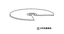
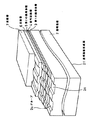
図1に、本発明の光学記録媒体10の一部を切り欠いた状態の概略斜視図を示し、図2に光学記録媒体10の層構造の示すための概略斜視図を示す。
なお、本発明の光学記録媒体10は、記録信号の記録および再生を複数回行うことができるものであり、例えば、ディスクカートリッジ(図示せず)に収納されて、記録再生装置(図示せず)に対して着脱自在に用いられる。
【0014】
本発明の光磁気記録媒体10は、図2に示すように、例えばポリカーボネート樹脂等の熱可塑性樹脂からなる透明基板2上に、第1の誘電体層3、信号記録層4、第2の誘電体層5、反射層6、および保護層7が順次積層されて形成された構成を有する。
【0015】
この図1および図2に示す光学記録媒体10に対して、信号の記録行う場合には、透明基板2形成面2f側から、所定の波長のレーザー光、例えば780nmの波長のレーザー光を、対物レンズにより集光し照射し、記録再生装置の記録用磁気ヘッドによって所定の磁界を印加することによって行う。
【0016】
このとき、光学記録媒体10は、信号記録層4が、レーザ光によって昇温し、保磁力が減少するため、記録用磁気ヘッドによって印加された磁界によって、記録信号に応じた磁区が信号記録層4に記録される。
【0017】
また、信号記録層4に記録された記録信号の再生を行う際には、信号記録を行う際のレーザ光よりも弱い出力のレーザ光を照射する。このとき、光学記録媒体10においては、レーザ光が信号記録層4に反射して戻ってきた戻り光に、カー効果やファラデー効果とぷの磁気光学効果によって偏光が生じる。記録再生装置は、戻り光の偏光方向を検出することによって、信号記録層4に記録された磁区の磁界の方向を検出し、これにより、記録信号を再生する。
【0018】
透明基板2は、レーザ光に対して透光性を有する硬質材料によって、略円盤形状に形成されている。透明基板2を形成する材料としては、例えば、ポリカーボネート樹脂、アクリル樹脂、ポリオレフィン樹脂、エポキシ樹脂等の各種樹脂材料や、石英ガラス等を用いることができる。
また、透明基板2上には、溝状のグルーブ2bが、円周方向にスパイラル状に形成されている。そして、光学記録媒体10は、グルーブ2bに沿って信号記録層4に対して信号の記録および再生が行われるように構成されている。すなわち、光学記録媒体10においては、グルーブ2bに沿って記録トラックが形成されている。
【0019】
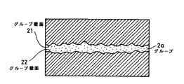
また、本発明の光学記録媒体10においては、グルーブ2bが、図3に示すように、半径方向に一定に周期で微小な幅で蛇行して形成されている、すなわち、グルーブ2aの両側の壁21、22は、それぞれ独立した形状にウォブル(蛇行)形状に形成されている。
【0020】
光学記録媒体10は、レーザ光によって記録あるいは再生が行われる際に、記録再生装置によって、グルーブ2bの蛇行の周期を読み取られる構成とされている。これにより、記録再生装置は、一定の周期で蛇行するグルーブ2bに基づいて、光学記録媒体10の回転速度を常に安定に保つことができる。
【0021】
また、グルーブ2bは、記録再生装置によって記録信号を信号記録層4に対して記録あるいは再生する際の位置決めの基準として用いられ、光学記録媒体10における記録信号の記録位置、すなわちアドレスを示す機能を有している。これにより、記録再生装置は、光学記録媒体10に対して記録および再生を行う際に、素早く正確な位置決めを行うことができる。
【0022】
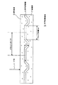
図4に本発明の光学記録媒体10の層構造を簡略化した断面図を示す。この場合、第1の誘電体層4、第2の誘電体層5、および反射層6の記載を省略して示す。
本発明の光学記録媒体10においては、グルーブ2aの幅をWとしたとき、0.470≦W/φ≦0.610であり、グルーブ2aの深さをDとしたとき、0.120≦D/(λ/n)≦0.142であり、グルーブ2aの壁面の角度θが、150°±10°であるものとする。
但し、φは照射するレーザ光のスポット径であり、λは真空中におけるレーザ光Lの波長とし、nは、透明基板の屈折率とする。
【0023】
また、本発明の光学記録媒体10の記録トラックのトラックピッチTPは、略1.5〔μm〕となされている。
【0024】
また、グルーブ2aの幅をWとし、グルーブ2aの深さをDとしたとき、
0.200≦{(D/(λ/n))/(W/φ)}≦0.330であるように形成されている。
但し、φは照射するレーザ光のスポット径であり、λは真空中におけるレーザ光の波長とし、nは、透明基板の屈折率とする。
【0025】
第1の誘電体層3および第2の誘電体層5は、C/N特性を向上させ、信号記録層4の腐食を防止する。
すなわち、透明基板2や、保護層7中には、塩素イオン等、金属を腐食させる成分が含まれている場合が多いので、第1の誘電体層3および第2の誘電体層5を、中間に信号記録層4を挟み込むようにして形成することにより、金属を腐食させる成分に直接影響されることを回避する。
【0026】
なお、第1の誘電体層3および第2の誘電体層5は、記録再生用のレーザ光Lの適用波長に対して、吸収能の低い材料により形成することが必要である。
例えば、Si3 N4 、SiN、AlN、Al2 O3 、AlSiNO、HfO2 、ZnS、ZrO2 、Y2 O3 、MgO、SiO2 、MgF2 、LiF等の材料を用いて、各種スパッタリング法等の薄膜形成技術により、透明基板2上に薄膜状に形成されてなる。但し、第1の誘電体層3を形成する材料としては、記録信号の記録あるいは再生を行うために入射されるレーザ光Lに対して透光性を有し、かつ酸素及び水分子が透過せず、酸素を含まない材料を用いることが望ましく、SiN、Si3 N4 、あるいはAlNを用いることが好ましい。
【0027】
本発明の光学記録媒体10を構成する信号記録層4は、この場合においては、光磁気記録層をその構成に備えるものであり、第1の誘電体層3状に、薄膜状に形成されている。
この光磁気記録層は、キュリー温度を超えた温度上昇によって保磁力が減少して外部磁界の方向に磁化反転するとともに、カー効果やファラデー効果等の磁気光学特性を有する材料によって形成される。例えば、TbFeCo、TbFeCoCr、GdFeCo等の希土類・遷移金属合金によって形成されている。
【0028】
なお、信号記録層4は、光磁気記録層のみによって単層で形成されていてもよいし、例えば、CAD(Center Aperture Ditector) ディスクや、MSR(Magnetic ally induced Super Resolution)ディスク等で提案されているように、誘電体層等をさらに積層した多層構造で形成されていてもよい。
【0029】
また、信号記録層4には、透明基板2のグルーブ2aの凹凸形状が転写されている。光学記録媒体10においては、グルーブ2aに沿って、信号記録層4に対して記録信号の記録再生が行われる記録トラックが形成されている。また、光学記録媒体10において、記録トラックのトラックピッチは、略1.5〔μm〕、誤差の範囲を考慮して1.5±0.01〔μm〕となるように構成されている。これにより、光学記録媒体10は、例えばトラックピッチが1.6〔μm〕とされた従来の光学記録媒体に比較して、記録密度を向上させることができる。したがって、光学記録媒体10は、従来の光学記録媒体と同等の外径寸法のままで、記録容量の大容量化を図ることができる。
さらに本発明の光学記録媒体においては、グルーブ2aの幅、グルーブ2aの深さ、およびグルーブの壁面の角度を照射するレーザ光のスポット径φ、および波長λとの関係において、数値的に規定したことにより、トラックピッチを従来に比して狭く形成した場合においても、信号の記録あるいは再生を行うレーザ光のデフォーカストレランスを充分に確保することができ、高い信頼性を保つことができる。
【0030】
光学記録媒体10を構成する反射層6は、第2の誘電体層5上に薄膜状に形成されている。反射層6は、信号記録層4および第2の誘電体層5を透過したレーザ光Lを反射する機能を有するとともに、信号記録層4に向けて照射されたレーザ光によって、この信号記録層4に熱が蓄積されることを防止するヒートシンクとしての機能を有する。
【0031】
光学記録媒体10は、反射層6がレーザ光を反射する機能を有していることから、記録再生時におけるレーザ光Lの利用効率を向上することができる。反射層6を形成する材料としては、熱的に良導体である非磁性金属元素又はその化合物を単独で、あるいは複合させて用いることが望ましく、例えば、Au,Al等によって形成されている。
【0032】
保護層7は、例えばスピンコーター等により塗布した紫外線硬化性樹脂を硬化すること等によって、反射層6上に薄膜状に形成されている。
光学記録媒体10は、保護層7を備えることによって、信号記録層4および反射層6が酸化等によって劣化してしまうことを回避することができる。
また、透明基板2上に形成された各層に傷が生じることを防止することができる。
【0033】
なお、保護層7は、各種の潤滑剤が内添されていてもよく、あるいは表面に各種の潤滑剤が塗布されていてもよい。
これにより、光学記録媒体10は、保護層7の形成面上において、記録再生装置の記録用磁気ヘッドを摺動させる場合に、この記録等磁気ヘッドや保護層7の磨耗および発熱等を回避することができる。
【0034】
次に、本発明の光学記録媒体について、具体的な〔実施例〕および〔比較例〕を挙げて説明するが、本発明は、以下に示す例に限定されるものではない。
なお、以下に示す各例においては、本発明の光学記録媒体として、光磁気ディスク(MD)を挙げて説明する。
【0035】
〔実施例1〕
以下のようにして、図1に示した構造の光学記録媒体10として、直径64mmの円盤形状を有する透明基板2上に、各層が順次形成された光磁気ディスクを作製した。
各層を形成するにあたって用いた材料を以下に示す。
透明基板2 :ポリカーボネート樹脂
第1の誘電体層3:SiN
信号記録層4 :TbFeCo
第2の誘電体層5:SiN
反射層6 :Al
保護層7 :紫外線硬化性樹脂
なお、各層の厚さ等は、それぞれ、公知のMDの規格に準じて形成し、記録トラックのトラックピッチを1.5〔μm〕に形成した。
また、〔実施例1〕の光磁気ディスクにおいては、以下の特徴を有する。
グルーブ2aの幅をWとしたとき、W/φ=0.5411である。
グルーブ2aの深さをDとしたとき、D/(λ/n)=0.1385である。
グルーブ2aの壁面の角度θが、最小値で142.9°、最大値で155.4°である。
グルーブ2aの幅をWとし、上記グルーブの深さをDとしたとき、
{(D/(λ/n))/(W/φ)}=0.25597である。
(但し、φは照射するレーザ光のスポット径であり、λは真空中におけるレーザ光の波長とし、nは、透明基板の屈折率とする。)
【0036】
〔実施例2〕〜〔実施例10〕
上記〔実施例1〕と同様の膜構成によりMDの規格に準じて、透明基板上に各層が成膜された光磁気ディスクを作製した。
これらについても記録トラックのトラックピッチを1.5〔μm〕に形成した。
〔実施例2〕〜〔実施例10〕の各光磁気ディスクは、上述したW/φ、D/(λ/n)、グルーブ2aの壁面の角度θの最小値および最大値、{(D/(λ/n))/(W/φ)}の値を、それぞれ変化させて互いに異なる値となるようにして作製した。
但し、〔実施例2〕〜〔実施例10〕のいずれの光磁気ディスクにおいても、0.470≦W/φ≦0.610であり、0.120≦D/(λ/n)≦0.142であり、グルーブの壁面の角度θが、150°±10°であり、0.200≦{(D/(λ/n))/(W/φ)}≦0.330であるものとした。
【0037】
〔比較例1〕
上記〔実施例1〕と同様の膜構成によりMDの規格に準じて、透明基板上に各層が成膜された光磁気ディスクを作製した。
これらについても記録トラックのトラックピッチを1.5〔μm〕に形成した。
〔比較例1〕の光磁気ディスクにおいては、以下の特徴を有する。
グルーブ2aの幅をWとしたとき、W/φ=0.5022である。
グルーブ2aの深さをDとしたとき、D/(λ/n)=0.1479である。
グルーブ2aの壁面の角度θが、最小値で155.2°、最大値で161.2°である。
グルーブ2aの幅をWとし、上記グルーブの深さをDとしたとき、
{(D/(λ/n))/(W/φ)}=0.29446である。
【0038】
〔比較例2〕
上記〔実施例1〕と同様の膜構成によりMDの規格に準じて、透明基板上に各層が成膜された光磁気ディスクを作製した。
これらについても記録トラックのトラックピッチを1.5〔μm〕に形成した。
〔比較例2〕の光磁気ディスクにおいては、以下の特徴を有する。
グルーブ2aの幅をWとしたとき、W/φ=0.6123である。
グルーブ2aの深さをDとしたとき、D/(λ/n)=0.1145である。
グルーブ2aの壁面の角度θが、最小値で154.2°、最大値で160.5°である。
グルーブ2aの幅をWとし、上記グルーブの深さをDとしたとき、
{(D/(λ/n))/(W/φ)}=0.18694である。
【0039】
〔比較例3〕
上記〔実施例1〕と同様の膜構成によりMDの規格に準じて、透明基板上に各層が成膜された光磁気ディスクを作製した。
これらについても記録トラックのトラックピッチを1.5〔μm〕に形成した。
〔比較例3〕の光磁気ディスクにおいては、以下の特徴を有する。
グルーブ2aの幅をWとしたとき、W/φ=0.4215である。
グルーブ2aの深さをDとしたとき、D/(λ/n)=0.1444である。
グルーブ2aの壁面の角度θが、最小値で154.8°、最大値で161.0°である。
グルーブ2aの幅をWとし、上記グルーブの深さをDとしたとき、
{(D/(λ/n))/(W/φ)}=0.34261である。
【0040】
上述した〔実施例1〕〜〔実施例10〕および〔比較例1〕〜〔比較例3〕の光磁気ディスクの、それぞれのW/φ、D/(λ/n)、グルーブ2aの壁面の角度θ、{(D/(λ/n))/(W/φ)}の値について、下記〔表1〕に示す。
【0041】
【表1】
〔特性の評価〕
上述のようにして作製した〔実施例1〕〜〔実施例10〕および〔比較例1〕〜〔比較例3〕の各光磁気ディスクに対して、MDの規格に準じた光学系を用いて、記録トラックに対してレーザ光を照射し、各光磁気ディスクにおけるレーザ光のデフォーカス量を変化させることによって、デフォーカス量と、上述した光磁気ディスクの、それぞれのW/φ、D/(λ/n)、グルーブ2aの壁面の角度θ、{(D/(λ/n))/(W/φ)}の値との関係について調べた。
このときの、測定条件を以下に示す。
光磁気ディスクの線速度 :1.2〜1.4〔m/s〕
レーザ光の波長λ :780〔nm〕
対物レンズの開口数N.A.:0.45
【0043】
上記〔実施例1〕〜〔実施例10〕および〔比較例1〕〜〔比較例3〕の光磁気ディスクにおけるレーザ光のデフォーカス量〔μm〕を変化させ、Near側と、Far側とでそれぞれ値を徐々に大きくしていったときに、このレーザ光がそれぞれの光磁気ディスクのグルーブから読み取るアドレスエラーが3個以上発生した瞬間のデフォーカス量〔μm〕を、上記〔表1〕に示す。
【0044】
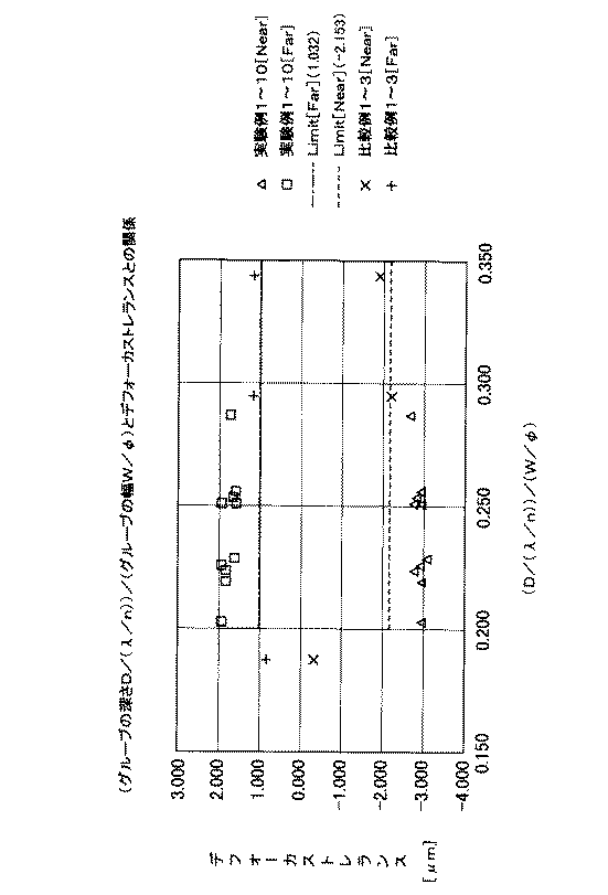
また、図5に、〔実施例1〕〜〔実施例10〕および〔比較例1〕〜〔比較例3〕の光磁気ディスクのデフォーカス量と、それぞれの光磁気ディスクの(W/φ)との関係、図6に、光磁気ディスクのデフォーカス量と、それぞれの光磁気ディスクの(D/(λ/n))との関係、図7に光磁気ディスクのデフォーカス量と、それぞれの光磁気ディスクの{(D/(λ/n))/(W/φ)}との関係をそれぞれ示す。
【0045】
なお、図5〜図7において、△印は、〔実施例1〕〜〔実施例10〕の光磁気ディスクにおいてNear側でレーザ光がそれぞれの光磁気ディスクのグルーブから読み取るアドレスエラーが3個以上発生した瞬間のデフォーカス量〔μm〕を示し、□印は、〔実施例1〕〜〔実施例10〕の光磁気ディスクにおいてFar側でレーザ光がそれぞれの光磁気ディスクのグルーブから読み取るアドレスエラーが3個以上発生した瞬間のデフォーカス量〔μm〕を示す。
また、×印は、〔比較例1〕〜〔比較例3〕の光磁気ディスクにおいてNear側でレーザ光がそれぞれの光磁気ディスクのグルーブから読み取るアドレスエラーが3個以上発生した瞬間のデフォーカス量〔μm〕を示し、+印は、〔比較例1〕〜〔比較例3〕の光磁気ディスクにおいてFar側でレーザ光がそれぞれの光磁気ディスクのグルーブから読み取るアドレスエラーが3個以上発生した瞬間のデフォーカス量〔μm〕を示す。
【0046】
図5〜図7において、一点鎖線は、MD規格でエラーの発生が許容されているFar側における限界値のデフォーカストレランス(1.032〔μm〕)を示し、破線は、MD規格でエラーの発生が許容されているNear側における限界のデフォーカストレランス(−2.153〔μm〕)を示す。
【0047】
また、図5〜図7においては、縦軸で示すデフォーカス量が、正の方向に値が大きくなるほどレーザ光の焦点位置が、信号記録面の奥に向かい、負の方向に値の絶対値が大きくなるほどレーザ光の焦点位置が信号記録面の手前に向かうことを示す。
【0048】
すなわち、図5〜図7においては、一点鎖線および破線の内側、すなわち一点鎖線と破線とで囲まれた領域にプロットがある場合は、わずかなデフォーカス量によってもアドレスエラーが頻繁に生じてしまうことを示している。
一方、図5〜図7においては、一点鎖線および破線の外側の領域にあるプロットがある場合は、デフォーカス量が大きくなったときでも、レーザ光が記録トラックに対して追従することができることを示している。
また、図5〜図7においては、Far側のデフォーカストレランスとNear側のデフォーカストレランスとの差が大きいほど、すなわち、両者のプロットの間隔の開きが大きいほど、デフォーカスマージンが大きいことを示している。
【0049】
図5、図6に示すように、記録トラックのトラックピッチを1.5〔μm〕になるように作製した場合において、グルーブの幅をWとしたとき、0.470≦W/φ≦0.610であり、グルーブの深さをDとしたとき、0.120≦D/(λ/n)≦0.142であり、グルーブの壁面の角度θが、150°±10°である〔実施例1〕〜〔実施例10〕の光磁気ディスクにおいては、いずれのプロットも、MD規格でエラーの発生が許容されているFar側における限界値のデフォーカストレランス(1.032〔μm〕)およびNear側における限界のデフォーカストレランス(−2.153〔μm〕)を越えており、デフォーカスマージンを大きくすることができた。
【0050】
また、図7に示すように、記録トラックのトラックピッチを1.5〔μm〕になるように作製した場合において、グルーブの幅をWとし、上記グルーブの深さをDとしたとき、0.200≦{(D/(λ/n))/(W/φ)}≦0.330であるものとした〔実施例1〕〜〔実施例10〕の光磁気ディスクにおいては、いずれのプロットも、MD規格でエラーの発生が許容されているFar側における限界値のデフォーカストレランス(1.032〔μm〕)およびNear側における限界のデフォーカストレランス(−2.153〔μm〕)を越えており、デフォーカスマージンを大きくすることができた。
【0051】
他方、グルーブ2aの深さをDとしたとき、D/(λ/n)の値が、0.142を越えている0.1479である〔比較例1〕の光磁気ディスクにおいては、図6から明らかなように、MD規格でエラーの発生が許容されているFar側における限界値のデフォーカストレランスおよびNear側における限界のデフォーカストレランスのそれぞれの値を達成したものの、上述した〔実施例1〕〜〔実施例10〕の光磁気ディスクと比較してデフォーカスマージンが小さいことがわかった。
【0052】
また、グルーブの幅をWとしたとき、W/φの値が0.610を越え、グルーブの深さをDとしたとき、D/(λ/n)の値が0.120未満であり、{(D/(λ/n))/(W/φ)}の値が0.200未満である〔比較例2〕の光磁気ディスク、および、W/φの値が0.470未満でありD/(λ/n)の値が0.142を越えており、かつ{(D/(λ/n))/(W/φ)}の値が0.330を越えている〔比較例3〕の光磁気ディスクにおいては、図5〜図7から明らかなように、MD規格でエラーの発生が許容されているFar側における限界値のデフォーカストレランスおよびNear側における限界のデフォーカストレランスのそれぞれの値の少なくともいずれかを達成できず、上述した〔実施例1〕〜〔実施例10〕の光磁気ディスクと比較してデフォーカスマージンが小さいことがわかった。
【0053】
上述したように、透明基板上に、記録トラックに沿ってグルーブが形成されて成り、グルーブの両側の壁は、それぞれ独立した形状にウォブルするようになされ、グルーブの幅をWとしたときに、0.470≦W/φ≦0.610の関係が成り立ち、グルーブの深さをDとしたときに、0.120≦D/(λ/n)≦0.142の関係が成り立ち、0.200≦{(D/(λ/n))/(W/φ)}≦0.330の関係が成り立り、かつグルーブの壁面の角度θが、150°±10°である光学記録媒体においては、記録トラックのトラックピッチを従来よりも狭い1.5〔μm〕とした場合においても、大きいデフォーカスマージンを得ることができることがわかった。
【0054】
【発明の効果】
本発明の光学記録媒体によれば、グルーブの幅W、グルーブの深さD、およびグルーブの壁面の角度θを、照射するレーザ光のスポット径φ、および波長λとの関係において、0.470≦W/φ≦0.610、0.120≦D/(λ/n)≦0.142、0.200≦{(D/(λ/n))/(W/φ)}≦0.330、かつθ=150°±10°と規定したことにより、記録トラックのトラックピッチを従来よりも狭い1.5〔μm〕とした場合においても、信号の記録あるいは再生を行うレーザ光のデフォーカストレランスを充分な大きさに確保することができ、信頼性に優れた光学記録媒体とすることができた。
【図面の簡単な説明】
【図1】本発明の光学記録媒体の一例の概略断面図を示す。
【図2】本発明の光学記録媒体の一部を切り欠いた断面層構造を示す概略斜視図を示す。
【図3】本発明の光学記録媒体のグルーブの形状の概略図を示す。
【図4】本発明の光学記録媒体の概略断面図を示す。
【図5】本発明の光磁気ディスクのデフォーカス量と光磁気ディスクの(W/φ)との関係を示す。
【図6】本発明の光磁気ディスクのデフォーカス量と光磁気ディスクの(D/(λ/n))との関係を示す。
【図7】本発明の光磁気ディスクのデフォーカス量と光磁気ディスクの{(D/(λ/n))/(W/φ)}との関係を示す。
【符号の説明】
2 透明基板、2a グルーブ、2f 透明基板形成面、3 第1の誘電体層、4 信号記録層層、5 第2の誘電体層、6 反射層、7 保護層、10 光学記録媒体、21,22 グルーブの壁面[0001]
BACKGROUND OF THE INVENTION
The present invention relates to a magneto-optical recording medium.
[0002]
[Prior art]
The optical recording medium is a recording medium that records and / or reproduces a recording signal by irradiating a signal recording layer with a laser beam by a recording / reproducing apparatus.
As an optical recording medium, a reproduction-only digital audio disk (so-called compact disk), an optical video disk (so-called laser disk), a magneto-optical disk, a phase change optical disk, and the like are known.
[0003]
As an example of such an optical recording medium, a multilayer structure in which a first dielectric layer, a signal recording layer, a second dielectric layer, and a metal reflective layer are sequentially laminated on a transparent substrate made of polycarbonate, for example. And a magneto-optical recording medium.
In such an optical recording medium, a signal is recorded on a signal recording layer along the recording track, or a recorded signal is reproduced, and a groove is formed on the transparent substrate along the recording track. Therefore, it is desired to realize a recording medium having a larger capacity by improving the recording density.
[0004]
For example, MD (Mini Disc), which is one of the standards for magneto-optical recording media, has a magnetic recording layer made of a magnetic thin film having an easy axis in the direction perpendicular to the substrate surface and having a large magneto-optic effect. The magnetic recording layer, the metal reflective layer, and the dielectric layer are laminated to form a recording portion having a laminated structure on the transparent substrate, and the recording portion is made of, for example, an ultraviolet curable resin. It has a configuration in which a protective layer is laminated.
[0005]
In such a mini disc (MD), conventionally, the recording track pitch is set to 1.6 [μm] and a music signal of 60 [minutes] or 74 [minutes] can be recorded. There is also realized an apparatus capable of recording a music signal of 80 [min] by further reducing the pitch to 1.5 [μm] to improve the recording density.
[0006]
[Problems to be solved by the invention]
However, as described above, when the recording track pitch is narrowed in order to increase the recording capacity, an allowable amount (hereinafter referred to as defocusing) with respect to the deviation of the focus of the laser beam irradiated for recording / reproduction. (Tolerance) becomes smaller.
When the defocus tolerance is reduced in this manner, it causes crosstalk or the like when recording / reproducing is performed, and depending on the type of recording / reproducing device when recording or reproducing is performed using a different type of recording / reproducing device. May cause problems such as inconvenience and difficulty in achieving compatibility, and may reduce the reliability of the optical recording medium.
[0007]
On the other hand, in recent years, the walls on both sides of the groove formed on the transparent substrate constituting the optical recording medium are each wobbled to an independent shape (to form a meandering shape, hereinafter simply referred to as wobble), A so-called ADIP (address-in-pregroove) type optical recording medium has been put into practical use in which an address can be taken by wobble.
Even in such an optical recording medium, in order to increase the capacity of the signal, it is necessary to reduce the interval between the grooves.
[0008]
Therefore, the present inventors have sufficiently secured the defocus tolerance of the irradiated laser beam even when the track pitch of the optical recording medium for decoding the address is narrowed by ADIP (address in pregroove). By doing so, it was decided to provide a highly reliable optical recording medium that can sufficiently cope with higher recording density.
[0009]
[Means for Solving the Problems]
In the optical recording medium of the present invention, a groove is formed on a transparent substrate along a recording track, and the walls on both sides of the groove are wobbled in independent shapes. When W is W, the relationship of 0.470 ≦ W / φ ≦ 0.610 holds, and when the groove depth is D, 0.120 ≦ D / (λ / n) ≦ 0.142 It is assumed that the relationship is established and the angle θ of the wall surface of the groove is 150 ° ± 10 °. The track pitch of the recording track is approximately 1.5 [μm], and the difference between the Far-side defocus tolerance and the Near-side defocus tolerance on the transparent substrate is 4.411 μm or more. . Where φ is the spot diameter of the laser beam to be irradiated, λ is the wavelength of the laser beam in vacuum, and n is the refractive index of the transparent substrate.
[0010]
According to the optical recording medium of the present invention, the relationship between the groove width, the groove depth, and the spot diameter φ of the laser beam for irradiating the groove wall angle and the wavelength λ is defined as described above. Even when the track pitch is narrow, a sufficient defocus tolerance of the laser beam for recording or reproducing the signal can be secured, and an optical recording medium having excellent reliability can be obtained.
[0011]
DETAILED DESCRIPTION OF THE INVENTION
The magneto-optical recording medium of the present invention is formed by forming grooves (grooves) along a recording track on a transparent substrate such as polycarbonate, and the walls on both sides of the groove are wobbled in independent shapes. The relationship of 0.470 ≦ W / φ ≦ 0.610 holds when the groove width is W, and when the groove depth is D, 0.120 ≦ D / It is assumed that the relationship (λ / n) ≦ 0.142 holds and the angle θ of the groove wall surface is 150 ° ± 10 °.
(Where φ is the spot diameter of the laser beam to be irradiated, λ is the wavelength of the laser beam in vacuum, and n is the refractive index of the transparent substrate.)
[0012]
Hereinafter, as an example of the optical recording medium of the present invention, a magneto-optical recording medium will be described with reference to the drawings. However, the optical recording medium of the present invention is not limited to the following examples.
That is, the optical recording medium of the present invention has grooves (grooves) formed along the recording track, and the walls on both sides of the groove are formed into independent wobble (meandering) shapes. For example, the present invention can be applied to an optical recording medium that performs at least one of recording and reproduction by irradiating a laser beam. For example, reproduction in which a predetermined fine uneven pattern corresponding to a recording signal is formed on a signal recording layer. It may be a dedicated optical recording medium, and can be applied to various optical recording media such as a phase change optical disk having a signal recording layer formed of a phase change material.
[0013]
FIG. 1 is a schematic perspective view showing a state in which a part of the
The
[0014]
As shown in FIG. 2, the magneto-
[0015]
When signals are recorded on the
[0016]
At this time, in the
[0017]
Further, when reproducing the recording signal recorded on the signal recording layer 4, a laser beam having a weaker output than the laser beam used for signal recording is irradiated. At this time, in the
[0018]
The transparent substrate 2 is formed in a substantially disk shape by a hard material having translucency with respect to laser light. As a material for forming the transparent substrate 2, for example, various resin materials such as polycarbonate resin, acrylic resin, polyolefin resin, and epoxy resin, quartz glass, and the like can be used.
On the transparent substrate 2, groove-like grooves 2b are formed in a spiral shape in the circumferential direction. The
[0019]
Further, in the
[0020]
The
[0021]
The groove 2b is used as a positioning reference when a recording signal is recorded on or reproduced from the signal recording layer 4 by a recording / reproducing apparatus, and has a function of indicating a recording position, that is, an address of the recording signal in the
[0022]
FIG. 4 shows a simplified cross-sectional view of the layer structure of the
In the
Where φ is the spot diameter of the laser beam to be irradiated, λ is the wavelength of the laser beam L in vacuum, and n is the refractive index of the transparent substrate.
[0023]
The track pitch TP of the recording track of the
[0024]
Further, when the width of the
It is formed so that 0.200 ≦ {(D / (λ / n)) / (W / φ)} ≦ 0.330.
Where φ is the spot diameter of the laser beam to be irradiated, λ is the wavelength of the laser beam in vacuum, and n is the refractive index of the transparent substrate.
[0025]
The first dielectric layer 3 and the second dielectric layer 5 improve C / N characteristics and prevent corrosion of the signal recording layer 4.
That is, since the transparent substrate 2 and the protective layer 7 often contain components that corrode metals such as chlorine ions, the first dielectric layer 3 and the second dielectric layer 5 are By forming the signal recording layer 4 so as to be sandwiched between them, it is possible to avoid being directly affected by a component that corrodes the metal.
[0026]
Note that the first dielectric layer 3 and the second dielectric layer 5 must be formed of a material having a low absorptivity with respect to the application wavelength of the recording / reproducing laser beam L.
For example, Si Three N Four , SiN, AlN, Al 2 O Three , AlSiNO, HfO 2 , ZnS, ZrO 2 , Y 2 O Three , MgO, SiO 2 , MgF 2 Using a material such as LiF, a thin film is formed on the transparent substrate 2 by thin film formation techniques such as various sputtering methods. However, as a material for forming the first dielectric layer 3, it has translucency with respect to the incident laser beam L for recording or reproducing the recording signal, and allows oxygen and water molecules to pass therethrough. It is desirable to use a material that does not contain oxygen, such as SiN, Si Three N Four Alternatively, it is preferable to use AlN.
[0027]
In this case, the signal recording layer 4 constituting the
This magneto-optical recording layer is formed of a material having a magneto-optical characteristic such as a Kerr effect or a Faraday effect while the coercive force decreases due to a temperature rise exceeding the Curie temperature and the magnetization is reversed in the direction of the external magnetic field. For example, it is made of a rare earth / transition metal alloy such as TbFeCo, TbFeCoCr, GdFeCo or the like.
[0028]
The signal recording layer 4 may be formed as a single layer only by a magneto-optical recording layer, and has been proposed, for example, as a CAD (Center Aperture Ditector) disk, an MSR (Magnetically induced Super Resolution) disk, or the like. As shown, it may be formed in a multilayer structure in which dielectric layers and the like are further laminated.
[0029]
Further, the concave and convex shape of the
Further, in the optical recording medium of the present invention, the relationship between the width of the
[0030]
The reflective layer 6 constituting the
[0031]
In the
[0032]
The protective layer 7 is formed in a thin film on the reflective layer 6 by curing, for example, an ultraviolet curable resin applied by a spin coater or the like.
By providing the protective layer 7 in the
Further, it is possible to prevent the layers formed on the transparent substrate 2 from being damaged.
[0033]
The protective layer 7 may be internally added with various lubricants, or may be coated with various lubricants on the surface.
Thereby, when the recording magnetic head of the recording / reproducing apparatus is slid on the surface on which the protective layer 7 is formed, the
[0034]
Next, the optical recording medium of the present invention will be described with specific [Examples] and [Comparative Examples], but the present invention is not limited to the following examples.
In each example shown below, a magneto-optical disk (MD) will be described as an example of the optical recording medium of the present invention.
[0035]
[Example 1]
As described below, a magneto-optical disk in which each layer was sequentially formed on a transparent substrate 2 having a disk shape with a diameter of 64 mm was manufactured as the
The materials used for forming each layer are shown below.
Transparent substrate 2: Polycarbonate resin
First dielectric layer 3: SiN
Signal recording layer 4: TbFeCo
Second dielectric layer 5: SiN
Reflective layer 6: Al
Protective layer 7: UV curable resin
The thickness of each layer was formed in accordance with a known MD standard, and the track pitch of the recording track was 1.5 [μm].
The magneto-optical disk of Example 1 has the following characteristics.
When the width of the
When the depth of the
The angle θ of the wall surface of the
When the width of the
{(D / (λ / n)) / (W / φ)} = 0.25597.
(Where φ is the spot diameter of the laser beam to be irradiated, λ is the wavelength of the laser beam in vacuum, and n is the refractive index of the transparent substrate.)
[0036]
[Example 2] to [Example 10]
A magneto-optical disk in which each layer was formed on a transparent substrate in accordance with the MD standard with the same film configuration as in the above [Example 1] was produced.
Also for these, the track pitch of the recording track was formed to 1.5 [μm].
Each of the magneto-optical disks of [Embodiment 2] to [Embodiment 10] has the above-described W / φ, D / (λ / n), the minimum value and the maximum value of the angle θ of the wall surface of the
However, in any of the magneto-optical disks of [Example 2] to [Example 10], 0.470 ≦ W / φ ≦ 0.610 and 0.120 ≦ D / (λ / n) ≦ 0. 142, the groove wall angle θ is 150 ° ± 10 °, and 0.200 ≦ {(D / (λ / n)) / (W / φ)} ≦ 0.330. .
[0037]
[Comparative Example 1]
A magneto-optical disk in which each layer was formed on a transparent substrate in accordance with the MD standard with the same film configuration as in the above [Example 1] was produced.
Also for these, the track pitch of the recording track was formed to 1.5 [μm].
The magneto-optical disk of [Comparative Example 1] has the following characteristics.
When the width of the
When the depth of the
The angle θ of the wall surface of the
When the width of the
{(D / (λ / n)) / (W / φ)} = 0.24946.
[0038]
[Comparative Example 2]
A magneto-optical disk in which each layer was formed on a transparent substrate in accordance with the MD standard with the same film configuration as in the above [Example 1] was produced.
Also for these, the track pitch of the recording track was formed to 1.5 [μm].
The magneto-optical disk of [Comparative Example 2] has the following characteristics.
When the width of the
When the depth of the
The angle θ of the wall surface of the
When the width of the
{(D / (λ / n)) / (W / φ)} = 0.18694.
[0039]
[Comparative Example 3]
A magneto-optical disk in which each layer was formed on a transparent substrate in accordance with the MD standard with the same film configuration as in the above [Example 1] was produced.
Also for these, the track pitch of the recording track was formed to 1.5 [μm].
The magneto-optical disk of [Comparative Example 3] has the following characteristics.
When the width of the
When the depth of the
The angle θ of the wall surface of the
When the width of the
{(D / (λ / n)) / (W / φ)} = 0.36261.
[0040]
The above-mentioned magneto-optical disks of [Example 1] to [Example 10] and [Comparative Example 1] to [Comparative Example 3] have respective W / φ, D / (λ / n) and wall surfaces of the
[0041]
[Table 1]
[Evaluation of properties]
For each of the magneto-optical disks of [Example 1] to [Example 10] and [Comparative Example 1] to [Comparative Example 3] produced as described above, an optical system conforming to the MD standard is used. By irradiating the recording track with laser light and changing the defocus amount of the laser light in each magneto-optical disk, the defocus amount and the respective W / φ, D / ( λ / n), the angle θ of the wall surface of the
The measurement conditions at this time are shown below.
Linear velocity of magneto-optical disk: 1.2 to 1.4 [m / s]
Laser light wavelength λ: 780 [nm]
The numerical aperture of the objective lens A. : 0.45
[0043]
By changing the defocus amount [μm] of the laser beam in the magneto-optical disks of [Example 1] to [Example 10] and [Comparative Example 1] to [Comparative Example 3], the Near side and the Far side are changed. When each value is gradually increased, the defocus amount [μm] at the moment when three or more address errors are read by the laser beam from the groove of each magneto-optical disk is shown in [Table 1]. Show.
[0044]
FIG. 5 shows the defocus amounts of the magneto-optical disks of [Example 1] to [Example 10] and [Comparative Example 1] to [Comparative Example 3], and (W / φ) of each magneto-optical disk. FIG. 6 shows the relationship between the defocus amount of the magneto-optical disk and (D / (λ / n)) of each magneto-optical disk, and FIG. 7 shows the defocus amount of the magneto-optical disk. The relationship with {(D / (λ / n)) / (W / φ)} of the magneto-optical disk is shown.
[0045]
In FIGS. 5 to 7, Δ marks indicate three or more address errors that cause the laser beam to read from the groove of each magneto-optical disk on the near side in the magneto-optical disks of [Embodiment 1] to [Embodiment 10]. Indicates the defocus amount [μm] at the moment of occurrence, and □ indicates an address error in which the laser beam is read from the groove of each magneto-optical disk on the Far side in the magneto-optical disk of [Embodiment 1] to [Embodiment 10]. Indicates the defocus amount [μm] at the moment when three or more occur.
In addition, in the magneto-optical disks of [Comparative Example 1] to [Comparative Example 3], the X mark indicates the defocus amount at the moment when three or more address errors occur when reading the laser beam from the groove of each magneto-optical disk on the near side [Μm] is indicated, and + indicates the moment when three or more address errors occur in reading the laser beam from the groove of each magneto-optical disk on the Far side in the magneto-optical disks of [Comparative Example 1] to [Comparative Example 3]. The defocus amount [μm].
[0046]
5 to 7, the alternate long and short dash line indicates the defocus tolerance (1.032 [μm]) of the limit value on the Far side where the occurrence of an error is allowed in the MD standard, and the broken line indicates an error in the MD standard. The limit defocus tolerance (−2.153 [μm]) on the Near side where generation is allowed is shown.
[0047]
5 to 7, the defocus amount indicated by the vertical axis increases as the value increases in the positive direction, so that the focal position of the laser beam moves toward the back of the signal recording surface, and the absolute value of the value in the negative direction. It shows that the focal position of the laser beam is closer to the front of the signal recording surface as becomes larger.
[0048]
That is, in FIG. 5 to FIG. 7, when there is a plot inside the one-dot chain line and the broken line, that is, the area surrounded by the one-dot chain line and the broken line, an address error frequently occurs even with a slight defocus amount. It is shown that.
On the other hand, in FIGS. 5 to 7, when there is a plot in the region outside the alternate long and short dash line and the broken line, the laser beam can follow the recording track even when the defocus amount increases. Show.
In FIGS. 5 to 7, the larger the difference between the Far-side defocus tolerance and the Near-side defocus tolerance, that is, the greater the gap between the plots of the two, the greater the defocus margin. Show.
[0049]
As shown in FIGS. 5 and 6, when the track pitch of the recording track is 1.5 [μm], when the groove width is W, 0.470 ≦ W / φ ≦ 0. When the groove depth is D, 0.120 ≦ D / (λ / n) ≦ 0.142, and the groove wall angle θ is 150 ° ± 10 ° [Examples] 1] to [Embodiment 10], all plots show the defocus tolerance (1.032 [μm]) and the near limit defocus tolerance on the Far side where errors are allowed to occur in the MD standard. The defocus tolerance (−2.153 [μm]) of the limit was exceeded, and the defocus margin could be increased.
[0050]
As shown in FIG. 7, when the recording track pitch is 1.5 [μm], when the groove width is W and the groove depth is D, 0. 200 ≦ {(D / (λ / n)) / (W / φ)} ≦ 0.330 In the magneto-optical disks of [Example 1] to [Example 10], any plots are used. Exceeding the limit defocus tolerance (1.032 [μm]) on the Far side and the limit defocus tolerance (−2.153 [μm]) on the Near side where errors are allowed to occur in the MD standard The defocus margin can be increased.
[0051]
On the other hand, when the depth of the
[0052]
Further, when the groove width is W, the value of W / φ exceeds 0.610, and when the groove depth is D, the value of D / (λ / n) is less than 0.120. The value of {(D / (λ / n)) / (W / φ)} is less than 0.200 [Comparative Example 2], and the value of W / φ is less than 0.470. The value of D / (λ / n) exceeds 0.142, and the value of {(D / (λ / n)) / (W / φ)} exceeds 0.330 [Comparative Example 3 As is apparent from FIGS. 5 to 7, each of the defocus tolerance of the limit value on the Far side and the defocus tolerance of the limit value on the Near side, which are allowed to generate errors according to the MD standard, respectively. At least one of the above values cannot be achieved, and the magneto-optics of the above-mentioned [Example 1] to [Example 10] It was found that the defocus margin was small compared to the Ki disk.
[0053]
As described above, a groove is formed along a recording track on a transparent substrate, and the walls on both sides of the groove are wobbled into independent shapes, and when the width of the groove is W, The relationship 0.470 ≦ W / φ ≦ 0.610 holds, and when the groove depth is D, the relationship 0.120 ≦ D / (λ / n) ≦ 0.142 holds, and 0.200 ≦ {(D / (λ / n)) / (W / φ)} ≦ 0.330 holds, and the angle θ of the wall surface of the groove is 150 ° ± 10 °. It has been found that a large defocus margin can be obtained even when the track pitch of the recording track is 1.5 [μm], which is narrower than the conventional one.
[0054]
【The invention's effect】
According to the optical recording medium of the present invention, the groove width W, the groove depth D, and the groove wall angle θ are 0.470 in relation to the spot diameter φ and the wavelength λ of the irradiated laser beam. ≦ W / φ ≦ 0.610, 0.120 ≦ D / (λ / n) ≦ 0.142, 0.200 ≦ {(D / (λ / n)) / (W / φ)} ≦ 0.330 And θ = 150 ° ± 10 °, the defocus tolerance of the laser beam for recording or reproducing the signal even when the track pitch of the recording track is 1.5 μm narrower than the conventional one. Can be secured in a sufficient size, and an optical recording medium having excellent reliability can be obtained.
[Brief description of the drawings]
FIG. 1 is a schematic cross-sectional view of an example of an optical recording medium of the present invention.
FIG. 2 is a schematic perspective view showing a cross-sectional layer structure in which a part of the optical recording medium of the present invention is cut away.
FIG. 3 is a schematic view of a groove shape of the optical recording medium of the present invention.
FIG. 4 is a schematic sectional view of the optical recording medium of the present invention.
FIG. 5 shows the relationship between the defocus amount of the magneto-optical disk of the present invention and (W / φ) of the magneto-optical disk.
FIG. 6 shows the relationship between the defocus amount of the magneto-optical disk of the present invention and (D / (λ / n)) of the magneto-optical disk.
FIG. 7 shows the relationship between the defocus amount of the magneto-optical disk of the present invention and {(D / (λ / n)) / (W / φ)} of the magneto-optical disk.
[Explanation of symbols]
2 transparent substrate, 2a groove, 2f transparent substrate forming surface, 3rd dielectric layer, 4 signal recording layer, 5 second dielectric layer, 6 reflective layer, 7 protective layer, 10 optical recording medium, 21 22 Wall surface of groove
Claims (2)
上記グルーブの両側の壁は、それぞれ独立した形状にウォブル(蛇行形状に形成すること、以下、単にウォブルと言う)するようになされ、
上記グルーブの幅をWとしたとき、0.470≦W/φ≦0.610であり、
上記グルーブの深さをDとしたとき、0.120≦D/(λ/n)≦0.142であり、
上記グルーブの壁面の角度θが、150°±10°であり、
上記記録トラックのトラックピッチが、略1.5〔μm〕であり、
上記透明基板上におけるFar側のデフォーカストレランスとNear側のデフォーカストレランスとの差が、4.411μm以上である
ことを特徴とする光学記録媒体。(但し、φは照射するレーザ光のスポット径であり、λは真空中におけるレーザ光の波長とし、nは、透明基板の屈折率とする。)Grooves are formed along the recording track on the transparent substrate,
The walls on both sides of the groove are wobbled into an independent shape (formed in a meandering shape, hereinafter simply referred to as wobble),
When the width of the groove is W, 0.470 ≦ W / φ ≦ 0.610,
When the depth of the groove is D, 0.120 ≦ D / (λ / n) ≦ 0.142,
Angle θ of the wall surface of the groove, Ri 0.99 ° ± 10 ° der,
The track pitch of the recording track is approximately 1.5 [μm],
An optical recording medium , wherein a difference between a Far-side defocus tolerance and a Near-side defocus tolerance on the transparent substrate is 4.411 μm or more . (Where φ is the spot diameter of the laser beam to be irradiated, λ is the wavelength of the laser beam in vacuum, and n is the refractive index of the transparent substrate.)
Priority Applications (3)
| Application Number | Priority Date | Filing Date | Title |
|---|---|---|---|
| JP2000206988A JP4333003B2 (en) | 2000-07-07 | 2000-07-07 | Optical recording medium |
| US09/838,515 US6501728B2 (en) | 2000-04-21 | 2001-04-19 | Optical disc having groove and land tracks |
| EP01109764A EP1152403A2 (en) | 2000-04-21 | 2001-04-20 | Optical recording medium |
Applications Claiming Priority (1)
| Application Number | Priority Date | Filing Date | Title |
|---|---|---|---|
| JP2000206988A JP4333003B2 (en) | 2000-07-07 | 2000-07-07 | Optical recording medium |
Publications (2)
| Publication Number | Publication Date |
|---|---|
| JP2002025119A JP2002025119A (en) | 2002-01-25 |
| JP4333003B2 true JP4333003B2 (en) | 2009-09-16 |
Family
ID=18703817
Family Applications (1)
| Application Number | Title | Priority Date | Filing Date |
|---|---|---|---|
| JP2000206988A Expired - Fee Related JP4333003B2 (en) | 2000-04-21 | 2000-07-07 | Optical recording medium |
Country Status (1)
| Country | Link |
|---|---|
| JP (1) | JP4333003B2 (en) |
-
2000
- 2000-07-07 JP JP2000206988A patent/JP4333003B2/en not_active Expired - Fee Related
Also Published As
| Publication number | Publication date |
|---|---|
| JP2002025119A (en) | 2002-01-25 |
Similar Documents
| Publication | Publication Date | Title |
|---|---|---|
| KR100634103B1 (en) | Magneto-optical recording medium and method of manufacturing magneto-optical recording medium | |
| JP2000123303A (en) | Magneto-optical head device and recording / reproducing device | |
| JP3433651B2 (en) | Magneto-optical recording medium and recording / reproducing method thereof | |
| JP2002319200A (en) | Optical disc and method of manufacturing the same | |
| US6501728B2 (en) | Optical disc having groove and land tracks | |
| US6731589B2 (en) | Substrate for optical recording media, optical recording medium, manufacturing process for optical recording media, and optical recording/reproducing method | |
| JP4333003B2 (en) | Optical recording medium | |
| US6144631A (en) | Information recording medium, and readout method and readout apparatus therefor | |
| CN1307634C (en) | Optical recording medium and optical recording device | |
| KR100613797B1 (en) | Optical recording medium | |
| CN1327419C (en) | Magneto-optical recording medium | |
| JP2001184727A (en) | Optical recording medium substrate, optical recording medium, and optical recording / reproducing method | |
| JP2002319197A (en) | Magneto-optical recording medium and method of manufacturing the same | |
| JP3770385B2 (en) | Magneto-optical disk reproducing method and magneto-optical disk apparatus | |
| JP2003036563A (en) | Optical recording medium | |
| JP2000030305A (en) | Information recording medium, method of reproducing the same, and reproducing apparatus | |
| CN100350485C (en) | Optical recording/reproducing method and optical recording medium | |
| JP2731521B2 (en) | Magneto-optical head | |
| JPWO2002089129A1 (en) | Optical recording medium, method for manufacturing optical recording medium, optical recording method and optical reproducing method for optical recording medium | |
| JP3999978B2 (en) | Magneto-optical recording medium | |
| JPS6342053A (en) | Information recording medium | |
| Sakamoto et al. | Anneal-less DWDD for 15 Gbit/in2 land-groove recording using a deep groove substrate and a red laser | |
| JP2003016704A (en) | Magneto-optical recording medium and method of manufacturing the same | |
| Tanaka et al. | System tolerance of 64-mm-diameter magneto-optical disks with a 4.7-Gigabyte capacity | |
| JPH0969244A (en) | Magneto-optical disk |
Legal Events
| Date | Code | Title | Description |
|---|---|---|---|
| A621 | Written request for application examination |
Free format text: JAPANESE INTERMEDIATE CODE: A621 Effective date: 20070308 |
|
| A977 | Report on retrieval |
Free format text: JAPANESE INTERMEDIATE CODE: A971007 Effective date: 20081006 |
|
| A131 | Notification of reasons for refusal |
Free format text: JAPANESE INTERMEDIATE CODE: A131 Effective date: 20081014 |
|
| A521 | Request for written amendment filed |
Free format text: JAPANESE INTERMEDIATE CODE: A523 Effective date: 20081211 |
|
| TRDD | Decision of grant or rejection written | ||
| A01 | Written decision to grant a patent or to grant a registration (utility model) |
Free format text: JAPANESE INTERMEDIATE CODE: A01 Effective date: 20090602 |
|
| A01 | Written decision to grant a patent or to grant a registration (utility model) |
Free format text: JAPANESE INTERMEDIATE CODE: A01 |
|
| A61 | First payment of annual fees (during grant procedure) |
Free format text: JAPANESE INTERMEDIATE CODE: A61 Effective date: 20090615 |
|
| FPAY | Renewal fee payment (event date is renewal date of database) |
Free format text: PAYMENT UNTIL: 20120703 Year of fee payment: 3 |
|
| FPAY | Renewal fee payment (event date is renewal date of database) |
Free format text: PAYMENT UNTIL: 20120703 Year of fee payment: 3 |
|
| FPAY | Renewal fee payment (event date is renewal date of database) |
Free format text: PAYMENT UNTIL: 20120703 Year of fee payment: 3 |
|
| FPAY | Renewal fee payment (event date is renewal date of database) |
Free format text: PAYMENT UNTIL: 20130703 Year of fee payment: 4 |
|
| LAPS | Cancellation because of no payment of annual fees |