JP4332988B2 - Signal processing apparatus and method - Google Patents
Signal processing apparatus and method Download PDFInfo
- Publication number
- JP4332988B2 JP4332988B2 JP2000132918A JP2000132918A JP4332988B2 JP 4332988 B2 JP4332988 B2 JP 4332988B2 JP 2000132918 A JP2000132918 A JP 2000132918A JP 2000132918 A JP2000132918 A JP 2000132918A JP 4332988 B2 JP4332988 B2 JP 4332988B2
- Authority
- JP
- Japan
- Prior art keywords
- signal
- section
- candidate
- unit
- video
- Prior art date
- Legal status (The legal status is an assumption and is not a legal conclusion. Google has not performed a legal analysis and makes no representation as to the accuracy of the status listed.)
- Expired - Fee Related
Links
- 238000000034 method Methods 0.000 title description 53
- 230000005236 sound signal Effects 0.000 claims description 100
- 238000001514 detection method Methods 0.000 claims description 82
- 238000000605 extraction Methods 0.000 claims description 35
- 238000003672 processing method Methods 0.000 claims description 6
- 230000008569 process Effects 0.000 description 44
- 230000006870 function Effects 0.000 description 32
- 230000008859 change Effects 0.000 description 24
- 238000001228 spectrum Methods 0.000 description 24
- 238000004364 calculation method Methods 0.000 description 23
- 230000002860 competitive effect Effects 0.000 description 21
- 238000010586 diagram Methods 0.000 description 21
- 238000011156 evaluation Methods 0.000 description 9
- 238000006243 chemical reaction Methods 0.000 description 5
- 239000000284 extract Substances 0.000 description 5
- 239000004576 sand Substances 0.000 description 5
- 230000003595 spectral effect Effects 0.000 description 5
- 238000010606 normalization Methods 0.000 description 4
- 230000000694 effects Effects 0.000 description 3
- 238000005516 engineering process Methods 0.000 description 3
- 238000004458 analytical method Methods 0.000 description 2
- 239000006185 dispersion Substances 0.000 description 2
- 230000004044 response Effects 0.000 description 2
- 238000010972 statistical evaluation Methods 0.000 description 2
- 230000007704 transition Effects 0.000 description 2
- 238000013528 artificial neural network Methods 0.000 description 1
- 230000010365 information processing Effects 0.000 description 1
- 239000004973 liquid crystal related substance Substances 0.000 description 1
- 230000003287 optical effect Effects 0.000 description 1
- 230000008520 organization Effects 0.000 description 1
- 239000004065 semiconductor Substances 0.000 description 1
- 239000002699 waste material Substances 0.000 description 1
Images


Classifications
-
- H—ELECTRICITY
- H04—ELECTRIC COMMUNICATION TECHNIQUE
- H04H—BROADCAST COMMUNICATION
- H04H60/00—Arrangements for broadcast applications with a direct linking to broadcast information or broadcast space-time; Broadcast-related systems
- H04H60/27—Arrangements for recording or accumulating broadcast information or broadcast-related information
-
- G—PHYSICS
- G11—INFORMATION STORAGE
- G11B—INFORMATION STORAGE BASED ON RELATIVE MOVEMENT BETWEEN RECORD CARRIER AND TRANSDUCER
- G11B27/00—Editing; Indexing; Addressing; Timing or synchronising; Monitoring; Measuring tape travel
- G11B27/10—Indexing; Addressing; Timing or synchronising; Measuring tape travel
- G11B27/102—Programmed access in sequence to addressed parts of tracks of operating record carriers
-
- G—PHYSICS
- G11—INFORMATION STORAGE
- G11B—INFORMATION STORAGE BASED ON RELATIVE MOVEMENT BETWEEN RECORD CARRIER AND TRANSDUCER
- G11B27/00—Editing; Indexing; Addressing; Timing or synchronising; Monitoring; Measuring tape travel
- G11B27/10—Indexing; Addressing; Timing or synchronising; Measuring tape travel
- G11B27/19—Indexing; Addressing; Timing or synchronising; Measuring tape travel by using information detectable on the record carrier
- G11B27/28—Indexing; Addressing; Timing or synchronising; Measuring tape travel by using information detectable on the record carrier by using information signals recorded by the same method as the main recording
-
- H—ELECTRICITY
- H04—ELECTRIC COMMUNICATION TECHNIQUE
- H04H—BROADCAST COMMUNICATION
- H04H20/00—Arrangements for broadcast or for distribution combined with broadcast
- H04H20/12—Arrangements for observation, testing or troubleshooting
- H04H20/14—Arrangements for observation, testing or troubleshooting for monitoring programmes
-
- H—ELECTRICITY
- H04—ELECTRIC COMMUNICATION TECHNIQUE
- H04H—BROADCAST COMMUNICATION
- H04H60/00—Arrangements for broadcast applications with a direct linking to broadcast information or broadcast space-time; Broadcast-related systems
- H04H60/35—Arrangements for identifying or recognising characteristics with a direct linkage to broadcast information or to broadcast space-time, e.g. for identifying broadcast stations or for identifying users
- H04H60/37—Arrangements for identifying or recognising characteristics with a direct linkage to broadcast information or to broadcast space-time, e.g. for identifying broadcast stations or for identifying users for identifying segments of broadcast information, e.g. scenes or extracting programme ID
-
- H—ELECTRICITY
- H04—ELECTRIC COMMUNICATION TECHNIQUE
- H04H—BROADCAST COMMUNICATION
- H04H60/00—Arrangements for broadcast applications with a direct linking to broadcast information or broadcast space-time; Broadcast-related systems
- H04H60/56—Arrangements characterised by components specially adapted for monitoring, identification or recognition covered by groups H04H60/29-H04H60/54
- H04H60/58—Arrangements characterised by components specially adapted for monitoring, identification or recognition covered by groups H04H60/29-H04H60/54 of audio
-
- H—ELECTRICITY
- H04—ELECTRIC COMMUNICATION TECHNIQUE
- H04H—BROADCAST COMMUNICATION
- H04H60/00—Arrangements for broadcast applications with a direct linking to broadcast information or broadcast space-time; Broadcast-related systems
- H04H60/56—Arrangements characterised by components specially adapted for monitoring, identification or recognition covered by groups H04H60/29-H04H60/54
- H04H60/59—Arrangements characterised by components specially adapted for monitoring, identification or recognition covered by groups H04H60/29-H04H60/54 of video
-
- H—ELECTRICITY
- H04—ELECTRIC COMMUNICATION TECHNIQUE
- H04H—BROADCAST COMMUNICATION
- H04H60/00—Arrangements for broadcast applications with a direct linking to broadcast information or broadcast space-time; Broadcast-related systems
- H04H60/68—Systems specially adapted for using specific information, e.g. geographical or meteorological information
- H04H60/72—Systems specially adapted for using specific information, e.g. geographical or meteorological information using electronic programme guides [EPG]
-
- H—ELECTRICITY
- H04—ELECTRIC COMMUNICATION TECHNIQUE
- H04H—BROADCAST COMMUNICATION
- H04H60/00—Arrangements for broadcast applications with a direct linking to broadcast information or broadcast space-time; Broadcast-related systems
- H04H60/76—Arrangements characterised by transmission systems other than for broadcast, e.g. the Internet
- H04H60/81—Arrangements characterised by transmission systems other than for broadcast, e.g. the Internet characterised by the transmission system itself
-
- H—ELECTRICITY
- H04—ELECTRIC COMMUNICATION TECHNIQUE
- H04N—PICTORIAL COMMUNICATION, e.g. TELEVISION
- H04N5/00—Details of television systems
- H04N5/76—Television signal recording
-
- G—PHYSICS
- G11—INFORMATION STORAGE
- G11B—INFORMATION STORAGE BASED ON RELATIVE MOVEMENT BETWEEN RECORD CARRIER AND TRANSDUCER
- G11B2220/00—Record carriers by type
- G11B2220/20—Disc-shaped record carriers
-
- G—PHYSICS
- G11—INFORMATION STORAGE
- G11B—INFORMATION STORAGE BASED ON RELATIVE MOVEMENT BETWEEN RECORD CARRIER AND TRANSDUCER
- G11B2220/00—Record carriers by type
- G11B2220/20—Disc-shaped record carriers
- G11B2220/25—Disc-shaped record carriers characterised in that the disc is based on a specific recording technology
- G11B2220/2525—Magneto-optical [MO] discs
-
- G—PHYSICS
- G11—INFORMATION STORAGE
- G11B—INFORMATION STORAGE BASED ON RELATIVE MOVEMENT BETWEEN RECORD CARRIER AND TRANSDUCER
- G11B2220/00—Record carriers by type
- G11B2220/90—Tape-like record carriers
-
- G—PHYSICS
- G11—INFORMATION STORAGE
- G11B—INFORMATION STORAGE BASED ON RELATIVE MOVEMENT BETWEEN RECORD CARRIER AND TRANSDUCER
- G11B27/00—Editing; Indexing; Addressing; Timing or synchronising; Monitoring; Measuring tape travel
- G11B27/10—Indexing; Addressing; Timing or synchronising; Measuring tape travel
- G11B27/19—Indexing; Addressing; Timing or synchronising; Measuring tape travel by using information detectable on the record carrier
- G11B27/28—Indexing; Addressing; Timing or synchronising; Measuring tape travel by using information detectable on the record carrier by using information signals recorded by the same method as the main recording
- G11B27/32—Indexing; Addressing; Timing or synchronising; Measuring tape travel by using information detectable on the record carrier by using information signals recorded by the same method as the main recording on separate auxiliary tracks of the same or an auxiliary record carrier
- G11B27/326—Indexing; Addressing; Timing or synchronising; Measuring tape travel by using information detectable on the record carrier by using information signals recorded by the same method as the main recording on separate auxiliary tracks of the same or an auxiliary record carrier used signal is a video-frame or a video-field (P.I.P.)
-
- G—PHYSICS
- G11—INFORMATION STORAGE
- G11B—INFORMATION STORAGE BASED ON RELATIVE MOVEMENT BETWEEN RECORD CARRIER AND TRANSDUCER
- G11B27/00—Editing; Indexing; Addressing; Timing or synchronising; Monitoring; Measuring tape travel
- G11B27/10—Indexing; Addressing; Timing or synchronising; Measuring tape travel
- G11B27/19—Indexing; Addressing; Timing or synchronising; Measuring tape travel by using information detectable on the record carrier
- G11B27/28—Indexing; Addressing; Timing or synchronising; Measuring tape travel by using information detectable on the record carrier by using information signals recorded by the same method as the main recording
- G11B27/32—Indexing; Addressing; Timing or synchronising; Measuring tape travel by using information detectable on the record carrier by using information signals recorded by the same method as the main recording on separate auxiliary tracks of the same or an auxiliary record carrier
- G11B27/327—Table of contents
-
- G—PHYSICS
- G11—INFORMATION STORAGE
- G11B—INFORMATION STORAGE BASED ON RELATIVE MOVEMENT BETWEEN RECORD CARRIER AND TRANSDUCER
- G11B27/00—Editing; Indexing; Addressing; Timing or synchronising; Monitoring; Measuring tape travel
- G11B27/10—Indexing; Addressing; Timing or synchronising; Measuring tape travel
- G11B27/34—Indicating arrangements
Description
【0001】
【発明の属する技術分野】
本発明は、例えば映像音声記録再生装置に適用されるものであり、特に、テレビジョン放送に付加されるコマーシャルメッセージを蓄積、閲覧、視聴、検索等する場合に好適な信号処理装置及び方法に関するものである。
【0002】
【従来の技術】
テレビジョン放送やラジオ放送等の公共放送は、一部の有料放送などを除き、企業や団体などを提供者とするコマーシャルメッセージ(以下、単にCMとする)を、番組本編中に挿入して放送されることが多い。
【0003】
視聴者は番組本編の視聴中にはCMを不要と感じることもある反面、CMは未知の商品などに対する直接的な情報源であることや、有名俳優の登場するCMやストーリー性のあるCMなどに代表されるように、作品としてCM自体が視聴対象となる場合も多い。
【0004】
しかしながら、番組に関しては、例えば番組表などにより事前に放送時間を知ることができるのに対し、CMに関しては、一般には何時放送されるのかを事前には知り得ないため、特定のCMを必要に応じて視聴することは難しい。そこで、例えば所定の時間内に放送されるCMがすべて蓄積され、必要に応じた閲覧、視聴、検索など可能となれば、上記のような多様な要求に対し、利便性の高い対応が図れると考えられる。
【0005】
【発明が解決しようとする課題】
ところで、従来より、放送信号からCMを検出に関する技術としては、例えば特開平8−317342号公報、特開平3−158086号公報、特開平3−2622872号公報などに、CMをスキップして視聴する技術が公開されている。しかしながら、これら技術ではCMの除去はできても、CMの蓄積、閲覧、視聴、検索などを行うことは出来ない。
【0006】
また、特開平10−224724号公報には、CMに付随する情報を検出、蓄積し、同一コマーシャルを1回だけ再生する技術が公開されている。しかしながら、この技術をしてもCMの蓄積、閲覧、視聴、検索などの要求を満たすものではなく、また、ステレオモードで放送されることの多いCM区間とスレテオ番組区間とが区別されないため、使用できる範囲は非常に限定されている。
【0007】
以上のようなことから、放送信号からCM部分を高精度に検出できると共に、そのCMの蓄積、閲覧、視聴、検索等を可能とすることが望まれている。
【0008】
そこで、本発明は、以上のような状況を鑑みてなされたものであり、例えば、放送信号からCM部分を高精度に検出できると共に、そのCMの蓄積、閲覧、視聴、検索等を可能とする、信号処理装置及び方法を提供することを目的とする。
【0009】
【課題を解決するための手段】
本発明の信号処理装置は、少なくとも第1の信号の区間とそれ以外の信号の区間とが時分割的に存在する入力信号から、所定の時間間隔を持つ信号の特徴的パターンに基づいて、第1の信号の候補区間を検出する候補区間検出手段と、上記候補区間内又はその前後の入力信号から、上記第1の信号らしさを表わす特徴量を抽出する特徴量抽出手段と、上記特徴量に基づき、上記第1の信号の区間を検出する検出手段と、上記検出手段により検出された上記第1の信号の区間について、ルール判定を行い第1の信号の区間を決定する判定手段と、上記第1の信号区間の判定結果に基づき、上記入力信号から第1の信号区間の信号を抽出する第1の信号抽出手段と、上記抽出された第1の信号を記録する記録手段とを有し、上記入力信号は、映像及び音声信号からなり、上記第1の信号の区間はコマーシャルメッセージ(CM)区間であり、上記候補区間は、音量条件と映像条件を満たす所定の長さのフレーム区間であり、上記判定手段で利用するルール判定は、CM候補区間中に他のCM候補が存在している場合は最小長さ優先ルールを利用し、前記最小長さ優先ルール適用後に他のCM候補が存在している場合には隣接優先ルールを利用し、前記隣接優先ルール適用後に他のCM候補が存在している場合にはスコア優先ルールを利用する判定である。
【0010】
また、本発明の信号処理方法は、少なくとも第1の信号の区間とそれ以外の信号の区間とが時分割的に存在する入力信号から、所定の時間間隔を持つ信号の特徴的パターンに基づいて、第1の信号の候補区間を検出する候補区間検出工程と、上記候補区間内又はその前後の入力信号から、上記第1の信号らしさを表わす特徴量を抽出する特徴量抽出工程と、上記特徴量に基づき、上記第1の信号の区間を検出する検出工程と、上記検出工程により検出された上記第1の信号の区間について、ルール判定を行い第1の信号の区間を決定する判定工程と、上記第1の信号区間の判定結果に基づき、上記入力信号から第1の信号区間の信号を抽出する第1の信号抽出工程と、上記抽出された第1の信号を記録する記録工程とを有し、上記入力信号は、映像及び音声信号からなり、上記第1の信号の区間はコマーシャルメッセージ(CM)区間であり、上記候補区間は、音量条件と映像条件を満たす所定の長さのフレーム区間であり、上記判定工程で利用するルール判定は、CM候補区間中に他のCM候補が存在している場合は最小長さ優先ルールを利用し、前記最小長さ優先ルール適用後に他のCM候補が存在している場合には隣接優先ルールを利用し、前記隣接優先ルール適用後に他のCM候補が存在している場合にはスコア優先ルールを利用する判定である。
【0011】
すなわち本発明によれば、入力信号から第1の信号を検出して記録することにより、入力信号から第1の信号を分離し、整理することが可能となる。また、本発明によれば、検出した第1の信号を特徴づける特徴量を抽出し、第1の信号と合わせて記録することにより、例えば第1の信号の閲覧、除去、検索などが容易に実現可能となる。また本発明によれば、第1の信号からそれを代表する索引情報を抽出し、表示することにより、第1の信号の閲覧、検索などが容易に実現可能となる。さらに、本発明によれば、記録された第1の信号から同一のものを例えば除去することで、記録効率を高め、また、閲覧時には同一の信号を複数回閲覧したり検索したり無駄を省くことができる。さらに、本発明によれば、第1の信号が部分的に同一若しくは類似したものを検出することで、様々な検索が可能となっている。
【0012】
【発明の実施の形態】
以下、本発明の好ましい実施の形態について、図面を参照しながら説明する。
【0013】
図1には、本発明の第1の実施の形態の放送信号処理装置の概略構成を示す。
【0014】
この図1に示す放送信号処理装置には、映像信号,音声信号,制御信号,番組ガイド信号等からなる信号200aが入力される。この入力信号200aは、地上波放送、衛星放送、ケーブル放送、電話回線等を通じて受信されたもの、若しくはそれらが図示しない別の記録装置に記録された後、再生されたものである。ここで、映像信号,音声信号は、番組本編及びCM部分を含む、放送信号の主要部を構成する信号である。また、制御信号には、放送モード、放送時刻、放送周波数もしくはチャンネル等の情報が含まれ、番組ガイド信号には、ディジタル放送や電話回線等により受信される、上記映像信号や音声信号に関連のあるデータを含む。以下の説明では、これらが単数の放送番組の信号であることを想定して説明するが、同時に複数のチャンネルの信号が入力されてもよい。
【0015】
この図1に示す放送信号処理装置において、CM検出部202は、上記映像信号/音声信号/制御信号/番組ガイド信号等よりなる入力信号200aから、少なくともCM区間の開始時刻(CM開始時刻と呼ぶ)及びCM区間の長さ(以下、CM長さと呼ぶ)を検出し、それらCM開始時刻及びCM長さを含むCM検出信号202aを出力する。なお、このCM検出部202の詳細な動作とCM開始時刻及びCM長さについては後述する。当該CM検出部202にて検出されたCM検出信号202aは、CM抽出部201とCM特徴抽出部203に送られる。
【0016】
CM抽出部201は、CM検出部202より供給されたCM検出信号202aに基づいて、入力信号202aからCM区間に相当する部分の信号201aを抽出する。すなわち、CM抽出部201は、CM検出部202より供給されたCM検出信号202aに含まれるCM開始時刻からCM長さで指定される時間までのCM区間に相当する信号部分(以下、適宜、CM部分信号201aと呼ぶ)を、上記入力信号200aから抽出し、そのCM区間に相当する映像信号/音声信号/制御信号/番組ガイド信号からなるCM部分信号201aを出力する。このCM部分信号201aは、CM記録部205に送られる。なお、上記CM検出部202からのCM検出信号202aは、入力信号200aに対して、その検出処理時間分の遅延が生じているので、CM抽出部201は、内設或いは外付けされた例えば磁気記録装置などからなる一時記憶装置を用いて、上記遅延分を吸収するようにしている。
【0017】
CM記録部205は、例えば磁気テープや磁気ディスク、光磁気ディスク、記録可能な光ディスク、半導体メモリ等の記録媒体の何れか一つ若しくはそれらの組み合わせを用いて、信号を記録及び再生する装置からなる。当該CM記録部205は、上記CM抽出部201からCM部分信号(CM区間に相当する映像信号/音声信号/制御信号/番組ガイド信号)201aが供給されたとき、そのCM部分信号201aを記録する。
【0018】
ここで、図2には、上記図1の構成のうち、上述したCM抽出部201、CM検出部202、CM記録部205の部分のみを抜き出したサブセットを示しており、図3にはこれら図2に抜き出した部分の動作の流れをフローチャートとして示す。
【0019】
図3において、先ず、図2のサブセットでは、ステップS220として、上記入力信号200aである映像信号/音声信号/制御信号/番組ガイド信号が順次入力されると、ステップS221として、その入力信号200aがCM抽出部201に前記内設或いは外付けされた一時記憶装置に保存される。
【0020】
同時に、図2のサブセットでは、前述のようにCM区間の開始時刻とCM区間の長さをCM検出部202により検出する。ここで、ステップS222として、入力信号200aについて、信号がCM区間に相当するか否かの検出を行い、CM区間であると判定した場合にはステップS223の処理に進み、CM区間でないと判定判定した場合にはステップS225の処理に進む。
【0021】
ステップS223の処理に進むと、CM抽出部201により入力信号200aからCM区間に相当する映像信号/音声信号/制御信号/番組ガイド信号の信号201aを抽出し、その後、ステップS224において当該抽出された信号をCM記録部205により保存する。
【0022】
その後、図2のサブセットでは、ステップS225の処理に進むと、CM抽出部201に一時的に記憶した信号を破棄し、ステップS220に戻って上述した処理を繰り返す。
【0023】
図1に戻り、CM特徴抽出部203では、上記CM検出部202より供給されたCM検出信号202aに基づいて、入力信号200aからCMの特徴を抽出する。すなわち、CM特徴抽出部203は、CM検出部202より供給されたCM検出信号202aに含まれるCM開始時刻からCM長さで指定される時間までのCM区間に相当する信号部分について、その信号部分が有する特徴を抽出(後述するCMとしての特徴を表すことになる特徴量を抽出)し、その特徴量203aをCM記録部205へ出力する。なお、上記CM検出部202からのCM検出信号202aは、入力信号200aに対して、その検出処理時間分の遅延が生じているので、CM特徴抽出部203は、内設或いは外付けされた例えば磁気記録装置などからなる一時記憶装置を用いて、上記遅延分を吸収するようにしている。当該一時記憶装置は、CM抽出部201の一時記憶装置と共有することが可能である。
【0024】
ここで、上記CMを特徴付ける特徴量としては、映像信号及び音声信号から抽出される、以下の振幅特徴量、スペクトル特徴量、線形予測係数、輝度ヒストグラム及び色ヒストグラム、平均輝度、輝度差分エネルギー、カットチェンジ回数及び時刻などのような物理量の一部又は全部を用いることができる。これらの特徴量は、同一のCMでは同一のパターンとなり、異なるCMでは異なるパターンとなるものであるから、CMを特徴付けるものと言うことができる。
【0025】
以下の説明では、入力音声信号及び映像信号は離散化されているとし、図4の(b)に示すS[m]により入力音声信号を表し、m=0,1,…,M−1により離散化された時間を表し、Mにより処理フレームに対応する離散時間を表わすことにする。また、図4の(a)に示すI[x,y;l]により入力映像信号を表し、l=0,1,…,L−1により入力映像の各映像フレームを表し、Lにより処理フレームに対応する映像フレーム数を、x=0,…,X−1は横方向の画素番号を、Xは横方向の映像サイズを、y=0,…,Y−1は縦方向の画素番号を、Yは縦方向の映像サイズを表すことにする。なお、処理フレームは、所定の時間長の処理単位であり、例えば250msとする。さらに、図4の(c)に示すように、CM区間長に対応するフレーム数をNで表わす。
【0026】
以下、各特徴量について説明する。
【0027】
先ず、処理フレームnの振幅特徴量A[n]は、フレームn内の音声信号の平均二乗振幅値であり、式(1)ように得られる。
【0028】
【数1】

これをCM区間の全フレームについてまとめたベクトルをA=(A[0],A[1],…,A[N-1])で表す。
【0030】
次に、処理フレームnのスペクトル特徴量F[k;n]は、フレームn内の平均スペクトルであり、式(2)ようにして得られる。
【0031】
【数2】
ただし、k=0,…,Kは離散化周波数を表わす番号であり、Kは対象とする最高周波数を表わす。この演算は、FFTや線形予測分析などを用いて実装される。周波数離散化のステップは、式(2)のkを再離散化することで、例えば1kHz毎といった線形なものにすることも、例えば1オクターブ毎といった非線型なものにすることもできる。また、これをCM区間の全フレームについてまとめたベクトルをF=(F[0;0],F[1;0],…,F[K-1;N-1])で表わす。
【0033】
次に、処理フレームnにおける線形予測係数P[k;n]は、例えばLinear Predictionof Speech (Markel他者、Springer‐Verag,1978)等に示される、LPCアルゴリズムを用いて計算される。k=0,…,K−1は、線形予測係数を表わす番号、Kは予測次数である。また、これをCM区間の全ワレームについてまとめたベクトルをP=(P[0;0],P[1;0],…,P[K-1;N-1])で表わす。
【0034】
次に、処理フレームnの輝度ヒストグラムH1[q;n]は、フレームn内の映像信号の輝度のヒストグラムである。ただし、q=0,…,Q−1は、輝度に対する升目を表わすインデックス番号であり、Qはビスとグラムの升目の数である。
【0035】
処理フレームnの色ヒストグラムHC[q;n]は、フレームn内の信号の各色毎の強度のヒストグラムである。ただし、q=0,…,Q−1は、色及び強度の升目を表わすインデックス番号であり、Qはヒストグラムの升目の数である。
【0036】
これら輝度ヒストグラム、色ヒストグラムをそれぞれCM区間の全フレームについてまとめたベクトルを、HI=(HI[0;0],HI[1;0],…,HI[Q-1;N-1])、及び、HC=(HC[0;0],HC[1;0],…,HC[Q-1;N-1])により表す。
【0037】
次に、処理フレームnの平均輝度B[n]は、フレームn内の映像信号の平均輝度であり、式(3)に示すように求められる。
【0038】
【数3】
これをCM区間の全フレームについてまとめたベクトルをB=(B[0],B[1],…,B[N-1])で表す。
【0040】
次に、処理フレームnの輝度差分エネルギーD[n]は、隣接する映像フレームの画素間差分エネルギーであり、例えば式(4)により求められる。
【0041】
【数4】
これをCM区間の全フレームについてまとめたベクトルをD=(D[0],D[1],…,D[N-1])で表わす。なおこの演算は、画素間差分に代えて、全画面の平均輝度の差分や、水平×垂直方向に8×8画素や16×16画素といったブロック間の差分を用いることもできる。
【0043】
次に、処理フレームnのカットチェンジ回数C[n]は、処理フレームn内で、隣接映像フレーム間の画素差分エネルギーが所定の閾値を越えるフレーム数であり、式(5)により求められる。
【0044】
【数5】
ただし、Countb a(f)は、aからbまでの区間内で評価式fが満足される回数を表わす関数であり、Dthsdは、輝度差分エネルギーに関する所定の閾値である。これをCM区間の全処理フレームについてまとめたベクトルをC=(C[0],C[1],…,C[N-1])で表わす。
【0046】
また、カットチェンジ時刻は、C[n]>0となるフレーム番号nとして求めることができ、CM区間全体でのカットチェンジ回数は、C[n]の総和として求めることができる。
【0047】
上記CM特徴抽出部203では、以上に説明した特徴量の一部又は全部を、各CM区間毎に検出する。すなわち、CM区間を特徴付ける特徴量は、式(6)に示されるベクトルVとして表わされることになる。
【0048】
V={A,F,P,HI,HC,B,D,C} (6)
また、特徴ベクトルVは、式(7)のようにも表すことができる。
【0049】
V={V[0],V[1],…,V[N-1] } (7) 但し、V[n]は式(8)に示されるように、処理フレームnにおける各々の特徴量を、ベクトルとしてまとめたものである。
【0050】
V={A[n],F[k;n],P[k;n],HI[n],HC[n],B[n],D[n],C[n] } (8)CM特徴抽出部203により抽出された上記の特徴量は、先に説明したCM抽出部201で抽出されたCM区間に相当するCM部分信号(映像信号/音声信号/制御信号/番組ガイド信号)201aと合わせて、CM記録部205に蓄積される。
【0051】
ここで、図5には、上記図1の構成のうち、上述したCM抽出部201、CM検出部202、CM特徴抽出部203、CM記録部205の部分のみを抜き出したサブセットを示しており、図6にはこれら図3に抜き出したサブセット部分の動作の流れをフローチャートとして示す。なお、図6のフローチャートにおいて、図3と重複する部分については図3と同じ指示符号を付してその説明は省略し、CM特徴抽出部203に係る部分に限って説明する。
【0052】
図6において、図5のサブセットでは、前記ステップS220により、の処理後、ステップS233の処理に進むと、上記入力信号200aである映像信号/音声信号/制御信号/番組ガイド信号が順次入力されると、ステップS231として、その入力信号200aがCM特徴抽出部203に前記内設或いは外付けされた一時記憶装置に保存される。
【0053】
同時に、CM検出部202によりCM区間の開始時刻とCM区間の長さが検出され、前記ステップS222においてCM区間であると判定した場合にはステップS233の処理に進み、CM区間でないと判定判定した場合にはステップS235の処理に進む。
【0054】
図5のサブセットでは、ステップS232の処理に進むと、CM特徴抽出部203により、CM区間に相当する映像信号/音声信号/制御信号/番組ガイド信号から、CMの特徴量を抽出し、ステップS234において当該抽出された特徴量をCM記録部205により保存する。
【0055】
その後、図5のサブセットでは、ステップS235の処理に進むと、CM特徴抽出部203に一時的に記憶した信号を破棄し、ステップS220に戻って上述した処理を繰り返す。
【0056】
図1に戻り、上述のようにしてCM記録部205に記録されたCM区間に相当するCM部分信号(映像信号/音声信号/制御信号/番組ガイド信号)201aと、CM区間の特徴量203aは、当該CM記録部205から読み出され、CM索引生成部206と、CM閲覧部208に送られる。
【0057】
CM索引生成部206は、CM記録部205から供給されたCM部分信号201aと特徴量203aに基づいて、CMを代表して索引となる情報を生成し、その情報(以下、CM索引情報と呼ぶ)206aをCM閲覧部208に送る。
【0058】
ここで、CM索引情報206aとしては、例えば以下の開始点画像、カット点画像、カット点映像、開始部音声、終了部音声等を示す情報を用いる。
【0059】
以下、これらのCM索引情報206aについて説明する。
【0060】
先ず、開始点画像とは、CM区間の開始点の画像であり、この開始点画像を索引情報の一つとする。
【0061】
カット点画像とは、CM区間の各カット点の画像であり、このカット点画像を索引情報の一つとする。なお、カット点は、特徴量C[n]が0より大きい処理フレームであるので、その時刻の画像を用いる。通例、一つのCM内にカット点は複数あるので、例えば最初又は最後のカット点といった、所定の基準により一枚の画像を選択する。
【0062】
カット点映像とは、CM区間の各カット点の画像をつないで時系列化し、映像としたものであり、このカット点映像を索引情報の一つとする。通例、一つのCM内にカット点は複数あるので、カット点の画像を全てつなぐことで新たな短い映像が生成される。
【0063】
開始部音声とは、CM区間の最初の部分の所定の時間、例えば2秒間の音声であり、この開始部音声を索引情報の一つとする。特に、音声の開始部では、短いCMのイントロダクションとして特徴的な音声が存在する場合があるため、これをCM索引とすることは有用である。
【0064】
終了部音声とは、CM区間の最初の部分の所定の時間、例えば2秒間の音声であり、この終了部音声を索引情報の一つとする。特に、音声の終了部では、商品名また会社や団体が共通に使用する映像や音声などが存在することが多いため、これをCMの索引とすることは有用である。
【0065】
上記CM記録部205からのCM部分信号201a及びCM区間の特徴量203a(以下これらを纏めて、適宜、記録部再生信号205aと呼ぶ)と、上記CM索引生成部206からのCM索引情報206aとが供給されるCM閲覧部208は、表示プロセッサ801と表示部802とからなる。
【0066】
表示部802は、例えばCRT(陰極線管)や液晶モニタ等の表示デバイスとスピーカなどで構成され、映像及び音声をユーザに提示する。
【0067】
また、CM閲覧部208の表示プロセッサ801には、ユーザ209の選択指示209aに応じてCM選択部207が発生したユーザ選択情報207aも供給される。すなわち、後述するように、表示部802に表示されたCM索引画像又は映像やアイコン等をユーザ209が閲覧208aし、その表示部802に表示されたCM索引画像又は映像やアイコン等に対して、例えばマウスやリモートコマンダ、タッチパネル等のポインティングデバイスを通じてユーザ209が選択指示209aを与えると、CM選択部207はその選択指示209aに応じたユーザ選択情報207aを発生し、このユーザ選択情報207aがCM閲覧部208の表示プロセッサ801に送られる。
【0068】
表示プロセッサ801は、上記CM索引情報206a及び記録部再生信号205a(特に映像/音声信号部分)と、上記CM選択部207からのユーザ選択情報027bとを受け、ユーザに提示する表示の操作を行う。なおこれは、プロセッサとソフトウェアなどにより実装される。
【0069】
以下、図7に示す表示部802の表示画面例を参照しながら、上記表示プロセッサ801の動作を説明する。
【0070】
表示プロセッサ801は、先ず、図7に示すように、上記CM索引情報206aに基づく複数のCMについてのCM索引画像又は映像810を、1画面内に配置して、表示部802に表示する。なお、CM索引画像又は映像810としては、各CMの開始点画像又はカット点映像が表示される。CM数が多い場合(CM索引画像又は映像810の数が多い場合)には、複数のページに分けた表示等が行われる。また、表示プロセッサ801は、CM選択部207においてユーザの指示を入力するためのアイコン811〜814等を、上記CM索引画像又は映像801と共に1画面内に配置して、表示部802に表示する。図7の表示例では、1画面内に12個のCM索引画像又は映像810と、CM再生アイコン811、音声専生アイコン812、前ページアイコン813、次ページアイコン814が表示されている。
【0071】
この図7のような表示がなされている状態で、CM選択部207からのユーザ選択情報207aを受けると、表示プロセッサ801は、そのユーザ選択情報207aに従い、表示を変更する。すなわち、表示プロセッサ801は、例えばCM選択部207を介してユーザ209が各CM索引画像又は映像810のうち何れか或いは複数を選択すると、その選択指示に応じたCM索引画像又は映像810を、例えばハイライト表示等する。
【0072】
また、図7のような表示がなされている状態で、例えばCM選択部207を介してユーザ209により各アイコンのうちの何れかが選択指示されると、表示プロセッサ801は、その選択指示がなされたアイコンに応じた処理を行う。すなわち、表示プロセッサ801は、例えば、CM再生アイコン811がユーザ選択情報207aにより指定された場合、上記CM索引画像又は映像810の中で既に選択されているCMの映像及び音声を再生させる。また、表示プロセッサ801は、例えば音声再生アイコン812がユーザ選択情報207aにより指定されると、上記CM索引画像又は映像810の中で既に選択されているCMの開始点音声又は終了点音声又は全音声を再生させる。また、表示プロセッサ801は、例えば、前ページアイコン813がユーザ選択情報207aにより指定されると、その時の表示画面の直前に表示されていたページのCM索引画像又は映像810群を画面上に表示させ、一方、例えば次ページアイコン814がユーザ選択情報207aにより指定されると、次のページのCM索引画像又は映像810群(閲覧されていない他のCM索引画像又は映像810群)を画面上に表示させる。
【0073】
ここで、図8には、上記図1の構成のうち、上述したCM記録部205、CM索引生成部206、CM閲覧部208、CM選択部207の部分のみを抜き出したサブセットを示しており、図9にはこれら図8に抜き出したサブセット部分の特にCM閲覧部208の動作の流れをフローチャートとして示す。
【0074】
図9において、CM閲覧部208は、先ず、ステップS240として、最初のページのCM群を指定し、次に、ステップS241として、上記指定されたCM群に対応する映像信号/音声信号をCM記録部205より取得し、その後、ステップS242として、CM索引生成部6によりCM索引情報206aが生成される。
【0075】
次に、ステップS243として、CM閲覧部208の表示プロセッサ801は、上記CM索引情報206aに基づいて、上記図7に示したような表示を行うための表示画面を生成して表示部802に表示させ、ステップS244として、その表示状態でユーザ209の指示入力(ユーザ選択情報207aの入力)がなされるまで待機する。
【0076】
ここで、ユーザ209の指示入力に応じて上記CM選択部207により生成されたユーザ選択情報207aが、CM索引を指定するものであった場合、表示プロセッサ801は、ステップS245として、ユーザ選択情報207aにより指定されたCM索引画像又は映像810を選択し、ステップS243として、当該選択したCM索引画像又は映像810をハイライト表示した表示画面を再生成して表示部802に表示させた後、ステップS244により、その表示状態でユーザ209の指示入力の待機状態となる。
【0077】
また、上記ユーザ選択情報207aが、CM再生アイコン811を指定するものであった場合、表示プロセッサ801は、ステップS246として、ユーザ選択情報207aにより既に指定されているCM索引画像又は映像810に対応するCMの映像及び音声信号をCM記録部205から再生させ、ステップS243として、当該再生された映像信号に応じた表示画面を再生成して表示部802に表示させた後、ステップS244により、その表示状態でユーザ209の指示入力の待機状態となる。
【0078】
また、上記ユーザ選択情報207aが、音声再生アイコン812を指定するものであった場合、表示プロセッサ801は、ステップS247として、ユーザ選択情報207aにより既に指定されているCM索引画像又は映像810に対応するCMの開始音声又は終了音声又は全音声信号をCM記録部205から再生させ、ステップS243として、当該再生された音声信号に応じた音声をスピーカから出力させた後、ステップS244により、その状態でユーザ209の指示入力の待機状態となる。
【0079】
また、上記ユーザ選択情報207aが、前ページアイコン813を指定するものであった場合、表示プロセッサ801は、ステップS248として、その直前に表示されていた表示画面のCM索引画像又は映像810に対応するCMの映像及び音声信号をCM記録部205から再生させ、ステップS243として、当該再生された映像信号に応じた表示画面を表示部802に表示させた後、ステップS244により、その表示状態でユーザ209の指示入力の待機状態となる。
【0080】
また、上記ユーザ選択情報207aが、次ページアイコン814を指定するものであった場合、表示プロセッサ801は、ステップS249として、次に表示される表示画面のCM索引画像又は映像810に対応するCMの映像及び音声信号をCM記録部205から再生させ、ステップS243として、当該再生された映像信号に応じた表示画面を表示部802に表示させた後、ステップS244により、その表示状態でユーザ209の指示入力の待機状態となる。
【0081】
以下、この繰り返しである。
【0082】
図1に戻り、前記CM記録部205に記録されている各CMの特徴ベクトルVは、信号205bとして特徴比較部204に送られる。
【0083】
特徴比較部204は、読み出し制御信号204aによりCM記録部205に記録されている各CMの特徴ベクトルVを読み出す。当該特徴比較部204は、上記CM記録部205から読み出した各CMの特徴ベクトルViを用いて、各CMが同一のCMか否かの比較を行う。ここで、iは各CMを区別するためのインデックス(インデックスの変数)である。当該特徴比較部204における2つのCMの特徴ベクトルViとVjの比較は次のようにして行う。
【0084】
先ず、評価関数J(i,j)を、式(9)のように計算する。
【0085】
【数6】
続いて、J(i,j)を所定のスレッショルドJthsdと比較し、Jthsd以下ならば同一のCMと判断し、Jthsdより大きければ異なるCMと判断する。このような比較を、CM記録部205に記録されている全てのCMについて行い、同一と判断されたCMのうち、どちらかをCM記録部205から除去する。これにより、CM記録部205に記録されている信号のうち、同一のCMにかかる信号は除去されることとなる。
【0087】
ここで、図10には、上記図1の構成のうち、上述したCM記録部205、特徴量比較部204の部分のみを抜き出したサブセットを示しており、図11にはこれら図10に抜き出したサブセット部分の特に特徴比較部204の動作の流れをフローチャートとして示す。
【0088】
図11において、特徴比較部204は、先ず、ステップS250として、上記インデックスの変数iを0にセットし、次に、ステップS251として、インデックスの変数jをi+1にセットする。
【0089】
続いて、特徴比較部204は、ステップS252として、特徴ベクトルVi,Vjより評価関数J(i,j)を計算し、所定の閾値Jthsdと比較する。ここで、当該比較の結果、閾値を下回っていると判定した場合(Yes)は、同一のCMと判断し、ステップS253として、特徴ベクトルVjで表わされるCMをCM記憶部205より除去する。一方、閾値を下回っていないと判定した場合(No)は、異なるCMであると判断し次のステップS254に進む。
【0090】
ステップS254に進むと、特徴比較部204は、jが対象とするCMの中で、最後のCM番号かどうかチェックする。ここで、最後のCMでないと判定した場合(No)は、ステップS255にてjをインクリメントし、続いてステップS252にて再び閾値との比較に戻る。一方、最後のCMであると判定した場合(Yes)は、ステップS256として、iが対象とするCMの中で、最後のCMであるかどうかをチェックする。ここで、最後のCMではないと判定した場合(No)は、ステップS257としてiをインクリメントし、続いてステップS251にて再びjのセットに戻る。最後のCMであった場合(Yes)は、処理を終了する。
【0091】
次に、本発明実施の形態の放送信号処理装置では、前述した図7の表示部802の表示画面例に更に検索アイコンを追加し、ユーザがCMの検索を行いたい場合に、当該検索アイコンを指示することで、ユーザ所望のCMを検索可能としている。図12には、検索アイコン815が追加表示された、表示部802の表示画面例を示す。以下、この図12の表示画面例を参照しながら前記CM記録部205、特徴量比較部204、CM閲覧部208、CM索引生成部206、CM選択部207等の動作を説明する。
【0092】
すなわち、上記検索アイコン815がユーザ209により指定されると、CM選択部207はそのユーザ選択に応じたユーザ選択情報207aを発生し、そのユーザ選択情報207をCM閲覧部208に送ると共に、特徴比較部204にも送る。
【0093】
特徴比較部204では、上記ユーザ選択情報207aが供給されると、前記CM索引画像又は映像810の中で既に選択されているCMとその特徴量が部分的に一致する特徴量を有するCMをCM記録部205内から検索する。
【0094】
すなわち、特徴比較部204では、CM選択部207からのユーザ選択情報207aにより、任意のCMiが指定された場合、そのCMiの特徴量とCM記録部205に記録されている他のCMjの特徴量との比較を行う。
【0095】
この比較の際には、先ず、CMの部分区間の評価関数J′(i,j)を、式(10)に従って計算することにより行う。
【0096】
【数7】
但し、式中のNsは、比較するCM部分区間の最初の処理フレーム番号、Neは比較するCM部分区間の最後の処理フレーム番号である。
【0098】
続いて、特徴比較部204は、その評価関数J′(i,j)を所定の閾値J′thsdと比較し、閾値より大きい場合には不一致と判断し、閾値より小さい場合には一致と判断する。
【0099】
なお、この比較において、例えば異なるCMであっても、同一提供者が提供するCMには、商品もしくは会社もしくは団体などに共通する映像/音声信号を挿入することで、視聴者に共通感をもたせるよう作成されている場合が多く存在する。また、そのための共通する映像/音声信号は、1秒程度であることが多い。従って、例えばNe=N−1をCM区間の最後のフレーム番号とし、Nsをその1秒前の処理フレームとすることで、一つのCMを指定すると、その同一会社の提供するCMを全て検索することが可能となる。
【0100】
また、特徴量の比較の際の評価関数J′(i,j)は、式(11)のように設定することもできる。
【0101】
【数8】
但し、Nwは一致検索を行う区間長であり、sは部分一致検索区間をCM区間の最初から最後までシフトしてゆくインデックス番号であり、Mins()は、全てのsのなかで最小となる値を表わす。またこの場合、ベクトルV[n]のなかで、映像に関する特徴量HI[n],HC[n],B[n],D[n],C[n]を除き、音声に関する特徴量A[n],F[k;n],P[k;n]のみを用いて行うことも有効である。
【0103】
このような関数を用いると、CM中の何れかの部分で一致するCMを検索することができる。これによると、例えば同じ音楽を背景音楽として用いるCMなどが検索できる。例えば同じ商品又は会社又は団体が、幾つかの継続性のあるCMを提供している場合、視聴者に共通性を感じさせるため同じ背景音楽が用いられることが多いことから、当該関数は、継続性をもって作られたCMなどを検索する際に有効な評価関数となる。
【0104】
なお、評価関数J(i,j)及びJ′(i,j)は、2つのCMの類似度と称することもある。
【0105】
上述のようにしてCM記録部205から検索されたCMの映像及び音声信号は、前記記録部再生信号205aとしてCM閲覧部208に送られる。
【0106】
またこのとき、前記索引生成部206では、上記特徴量が一致するCMの索引情報を生成し、その索引情報206aをCM閲覧部208に送る。
【0107】
これにより、CM閲覧部208では、上記検索されたCMの映像が表示され、また音声が再生可能となる。
【0108】
図13には、上記図1の構成のうち、上述したCM検索を実現するための、CM記録部205、特徴量比較部204、CM索引生成部206、CM閲覧部208、CM選択部207の部分のみを抜き出したサブセットを示しており、図14にはこれら図13に抜き出したサブセット部分の特に特徴比較部204の動作の流れをフローチャートとして示す。なお、図14のフローチャートは、前述した図9のフローチャートのステップS244の後段の処理となるものである。
【0109】
この図14において、図9のフローチャートのステップS244のユーザ指示待機状態となっているとき、例えば上記ユーザ選択情報207aが、CM件サックアイコン815を指定するものであった場合、特徴比較部204は、ステップS260として、インデックスの変数iを、上記選択されているCMのインデックスにセットし、次に、ステップS261として、インデックスの変数jを0にセットする。
【0110】
続いて、特徴比較部204は、ステップS262として、特徴ベクトルVi,Vjより評価関数J′(i,j)を計算し、所定の閾値J′thsdと比較する。ここで、閾値J′thsdを下回っていると判定した場合(Yes)には、類似するCMと判断され、ステップS263において、特徴ベクトルVjで表されるCMをマークしておく。一方、閾値J′thsdを下回っていないと判定した場合(No)は、類似していないCMと判断して次のステップS294に進む。
【0111】
ステップS264に進むと、特徴比較部204は、jが対象とするCMの中で、最後のCM番号かどうかをチェックする。ここで、最後のCMではないと判定した場合(No)は、ステップS265にてjをインクリメントした後、ステップS262に戻り再び閾値との比較を行う。一方、最後のCMであった場合(Yes)には、ステップS266として、マークしたCM群をまとめて指定し、図9に示したステップS241、すなわち指定されたCM群の信号をCM記録部205より取得する処理へ戻る。
【0112】
なお、本実施の形態において、上述した同一CMの除去を行わず、全てのCMを蓄積し、かつ検索を全CM区間の一致にて行うことで、同一のCMが放送された回数及びその時刻を検索することも可能となる。
【0113】
以上説明したようなことから、本実施の形態の放送信号処理装置によれば、放送信号からCM部分だけを抽出し、蓄積することが可能となり、これによって、例えば、番組部分を記録せず、CM部分のみを蓄積するデータベース装置を提供することが可能となる。
【0114】
また、本実施の形態の放送信号処理装置によれば、放送信号からCM部分だけを抽出し、該CM部分を特徴付ける特徴量を抽出し、それらを蓄積することが可能となり、これによって、例えば、番組部分を記録せず、CM部分及びその特徴量のみを蓄積するデータベース装置を提供することが可能となる。これらの特徴量は、特に同一CM検索、類似CM検索などに有用なものである。
【0115】
また、本実施の形態の放送信号処理装置によれば、上述のように蓄積されたCMを、表示、閲覧することが可能となり、これによって、視聴者(ユーザ)は蓄積されたCMの一覧の表示、再生及び検索などを行うことができる。これは、CMを探して視聴する場合に有用である。
【0116】
また、本実施の形態の放送信号処理装置によれば、上述のように蓄積されたCMから、同一のCMを除去することが可能となり、これによって、蓄積容量が節約されると同時に、同一のCMを何度も閲覧してしまう手間を回避可能となる。
【0117】
また、本実施の形態の放送信号処理装置によれば、類似するCMの検索が可能となり、これによって、蓄積されたCMから、同一商品のCM、同一提供者のCMなどを、容易に検索、表示することが可能となる。
【0118】
また、本実施の形態の放送信号処理装置によれば、CMの最後の部分が一致するものを検索することができる。すなわち、CMの最後の部分には商品、会社、団体等に共通する映像や音声が含まれることが多いことから、これにより、同一商品や提供者のCMを容易に検索、表示可能となる。
【0119】
さらに、本実施の形態の放送信号処理装置によれば、背景音楽の一致するCMを検索することができる。すなわち、同一商品や提供者が、継続性をもって作成したCMには同一の背景音楽が用いられることが多いため、これにより、継続性をもって作成されたCMを、に検索、表示可能となる。
【0120】
最後に、本実施の形態の放送信号処理装置によれば、同一CMが放送された時刻及び回数を計測することができる。これは、例えばCMの作成者などが、放送予定と実際の放送を比較する等の目的に対して、有効な装置となる。
【0121】
次に、本発明実施の形態において、放送信号からCMを検出し、CM開始時刻やCM長さを検出する、図1のCM検出部202の詳細について以下に説明する。
【0122】
以下、CM検出部202において、例えばTV放送信号からCM部分を検出する際の原理について概説する。なお、以下の説明で、特徴量という記載は、前記CM特量抽出部203や特徴比較部204における特徴と同じ場合と異なる場合とがあるが、それらは共にCMの特徴を表すものであるため、ここではそれらを特に区別せずに使用している。
【0123】
一般に、TV放送されるCMは、放送者の指定する規格に基づいて製作されるため、その「時間長(1つのCMの時間)はごく少数の種類に限定」される。例えば日本国内においては、特殊な例を除くほぼ全てのCMが、15秒、30秒、60秒の長さで製作されている。
【0124】
また、CMの放送時には、番組本編や他のCMとは独立に製作されたものがTV放送ストリーム中に挿入されるため、各CMの前後では必然的に「音声レベルが下がる(すなわち小音量となる)」こと、及び、「映像信号が切り替わる」こと、という特徴を持つ。ここで、「音声レベルが下がる」とは、必ずしも無音(ここでは極微小なノイズしかない部分という意味)と同義ではない。すなわち、実際には、CMと本編との切り替えのタイミングなどにより、必ずしも完全に無音とはならないまま切り替わることがあるからである。
【0125】
上述したように、CMについての「規定時間長(少数種類の時間長)」、「小音量」、「映像切り替わり」という3つの特徴は、ほぼ全てのCMが満たす条件である。本発明では、以下、これら3つの特徴に基づく条件を「必須条件」と称することにする。
【0126】
したがって、TV放送信号から当該必須条件に対応する信号部分を検出するようにすれば、誤棄却がほとんどなく決定論的にCMの候補(すなわちCMであろうと思われる信号部分)を検出することが可能となる。但し、番組本編内にも、偶然そのような必須条件を満たしてしまう部分が多く存在するため、上記必須条件を用いただけでは、番組本編の一部をCM候補として誤検出してしまう虞が残る。
【0127】
一方で、上記必須条件と比べて例外は多く存在するものの、CMの性質上、多くのCMが満たすか若しくは一定の傾向を示す特徴としては、以下のようなものがある。
【0128】
1)CMの前後(CMが開始される直前とCMが終了して本編番組が開始又は再開される直前)では、通常の番組本編内よりも音声レベルが低くなることが多い。
【0129】
2)CMと番組本編との間、及び、あるCMと他のCMとの間の、ほぼ無音となる区間長は、数百ミリ秒程度であることが多い。
【0130】
3)TV放送内に含まれる有音区間は、CMの規定時間長(15秒、30秒、60秒等)より百ミリ秒程度以上短いことが多く、また1秒程度以上短いことは少ない。
【0131】
4)ステレオ音声信号の左チャンネル(Lチャンネル)と右チャンネル(Rチャンネル)の相関値は、1より有意に小さいことが多い。
【0132】
5)CM期間中は、番組本編より音量が大きめである傾向がある。
【0133】
6)CMの放送モードは、ステレオモードであることが多い。
【0134】
7)CM区間では、複数のCMが連続して放送されることが多い。
【0135】
8)CM期間中は、映像カットの切り替わり頻度が高いことが多い。
【0136】
9)逆に、CM期間中であっても、カットの切り替わり頻度が極端に低いものがある(例えば静止画によるCMなど)。
【0137】
10)番組本編とCMとの境界や、あるCMと他のCMの境界では、音質が大きく変化することが多い。
【0138】
11)CMは、音声と音楽を同時に含むことが多い。
【0139】
12)番組編成上、毎時丁度の時刻近辺では、CMが放送される確率が高い。
【0140】
13)同様に、毎時30分付近でもCMが放送される確率が高い。
【0141】
14)番組のジャンルによってCMが放送される確率の高い時間帯がある(例えばサッカー中継のハーフタイムなど)。
【0142】
本発明では、以下、これらの特徴に基づく条件を「付加条件」と称することにする。すなわち、当該付加条件は、CMが、規格に基づいて製作されるという制約、短い時間で宣伝効果を上げるためのものであるという制約、及び、番組構成上の都合などによる制約の元で製作された結果として、TV放送信号上に現れてくることによる条件である。したがって、この付加条件は、決定論的な取り扱いができるほど確実な条件ではないものの、CMである可能性(CMらしさ)を評価する際の有効な条件となる。
【0143】
さらに、TV放送においては、同時に同じチャンネルで複数の映像及び音声が放送されることは物理的にありえないという特徴がある。すなわち、TV放送信号からCMであろうと思われる信号部分(CM候補)を検出しようとする場合において、例えば、TV放送信号中に、上記付加条件を満たす複数の映像及び音声区間がオーバーラップして存在し、何らかの処理の結果、当該オーバーラップ区間でCM候補が検出されたとしても、そのオーバーラップしている複数の映像及び音声内の少なくともどちらかの区間は、正しいCM区間ではあり得ない。本発明では、TV放送におけるこのような特徴に基づく条件を、「論理条件」と称することにする。
【0144】
本発明では、以上説明した「必須条件」、「論理条件」、「付加条件」を合理的かつ効果的に利用することにより、TV放送信号から高精度でCM部分を検出可能としている。
【0145】
より具体的に言うと、本発明では、「必須条件」に基づき、決定論的にTV放送信号中からCM候補(CMであろうと思われる信号部分)を抽出し、「付加条件」に基づくCMらしさ(CMである可能性)の統計論的な評価によってCM候補を選択し、「論理条件」によりCM候補のオーバーラップ関係を解消することにより、精度の高いCM検出を実現するものである。
【0146】
図15には、上記CM検出部202の第1の具体例の詳細な構成を示す。当該CM検出部202は、大別して、フロントエンド部とバックエンド部とから構成されている。また、図中の動作制御部23は、放送チャンネルを示すチャンネル情報1bに基づいて、明らかにCMが放送されない放送チャンネルであるか否か判断し、その判断結果に応じて、当該図15の各部におけるCM検出動作を行わないように制御するものである。
【0147】
先ず、図15のフロントエンド部から説明する。
【0148】
この図15において、当該フロントエンド部には、前記入力信号200aに含まれる映像信号2a、音声信号2b、及び放送モード信号2cが入力される。また、フロントエンド部には、図示しない時計により発生した時間情報3aも入力される。
【0149】
映像信号2aは、A/D変換器10にてディジタル化され、フレームメモリ11に蓄えられる。なお、フレームメモリ11には、少なくとも2フレーム分の映像信号を蓄積可能なメモリである。当該フレームメモリ11からフレーム毎に読み出された映像信号は、カットチェンジ検出器12に送られる。
【0150】
カットチェンジ検出器12は、フレームメモリ11より供給されたフレーム毎の映像信号に基づいて、映像が急激に変化するフレーム(以下、映像変化フレームと呼ぶ)と、輝度が一様となるフレーム(以下、一様輝度フレームと呼ぶ)を検出する。
【0151】
すなわち、カットチェンジ検出器12は、フレームメモリ11に蓄えられた時間的に隣接する2つのフレーム映像間で、各画素毎に輝度の差分の自乗和を求め、当該自乗和が所定の閾値を越えた場合に、上記隣接する2つのフレームのうちの時間的に後のフレームを、上記映像が急激に変化する映像変化フレームとして検出する。また、カットチェンジ検出器12は、フレームメモリ11に蓄えられた各フレーム映像の輝度の分散を求め、その輝度の分散値が所定の閾値以下である場合に、そのフレームを一様輝度フレームであるとして検出する。なお、フレームの間隔(NTSC方式では約30ms)が、後述する音声信号処理において説明するフレーム周期と一致しない場合には、当該フレーム間隔を再離散化することによって、フレーム周期と一致させておくようにする。
【0152】
以下、当該カットチェンジ検出器12における映像変化フレームと一様輝度フレームの検出について、より具体的に説明する。
【0153】
ここで、離散化された映像信号の横サイズをX、縦サイズをY、縦横の画素番号をx,yとし、第nフレームの映像をIn(x,y)、当該第nフレームに対して時間的に1フレーム前の第n−1フレームの映像をIn-1(x,y)として表わすと、第nフレームと第n−1フレームの間の各画素毎の輝度差分の二乗和D[n]は、式(12)により得られ、また、第nフレームの輝度分散値V[n]は、式(13)により得られる。
【0154】
【数9】
また、このときのカットチェンジ検出器12の検出出力C[n]は、式(14)により表わされる。
【0156】
【数10】
ただし、式中のDthsdは上記映像変化フレームを検出する際の前記自乗和に対する所定の閾値であり、Vthsdは上記一様輝度フレームを検出する際の前記輝度の分散値に対する所定の閾値である。
【0158】
当該カットチェンジ検出器12の検出出力C[n]は、映像信号についての特徴量として特徴量バッファ18へ送られる。
【0159】
なお、上記の2つのフレーム映像間で輝度差分を求める際には、2フレーム分の映像信号を蓄積可能なメモリが必要となり、また、2フレーム分の映像信号に対する演算量も必要となる。そこで、例えばフレーム映像全面を同時に処理する代わりに、フレーム映像を適切な小ブロック毎に分け、その小ブロック毎に輝度差分を求めるようにしたり、或いは、フレーム映像間の各画素毎に輝度差分を求めるのではなく、各フレーム映像毎に輝度ヒストグラムを求めて、その輝度ヒストグラムのフレーム間差分を求めるようにしたり、又は、各フレーム映像毎に平均輝度を求めて、その平均輝度のフレーム間差分を求めるようにするで、メモリ容量や演算量を減らすことも可能である。逆に、メモリや演算量に余裕がある場合には、例えば、カラー映像におけるR(赤),G(緑),B(青)成分のようなカラー成分毎に、上記輝度差分やカラーヒストグラム差分を求めることで、より検出精度を高めることも可能である。
【0160】
次に、音声信号2bは、A/D変換器13にてディジタル化され、音声信号バッファ14に蓄えられる。なお、音声信号バッファ14には、少なくとも所定時間T1(例えば30ms、以下、これを1フレーム長とする)分の左(L)右(R)2チャンネルのステレオ音声信号を蓄積可能なメモリである。当該音声信号バッファ14から読み出された音声信号は、振幅検出器15、相関検出器16、スペクトル検出器17に送られる。
【0161】
振幅検出器15は、音声信号バッファ14に蓄えられた音声信号を用いて、所定の時間T2(例えば15ms、以下、これを1フレーム周期とする)毎の短時間平均二乗振幅を検出する。すなわち、振幅検出器15は、音声信号バッファ14に左右2チャンネルのステレオ音声信号が蓄積されている場合、当該音声信号バッファ14より読み出された左右2チャンネルのステレオ音声信号SL[m],SR[m]から、所定の時間T2(15ms、1フレーム周期)毎に、短時間平均二乗振幅を検出する。なお、上記m(m=0,・・・,M−1)は、離散化された時間を表わすバッファ内のサンプル番号であり、最大番号Mが1フレーム長T1に対応する。
【0162】
より具体的に説明すると、振幅検出器15は、第nフレームにおける左右2チャンネルの音声信号の平均二乗振幅A[n]を式(15)により計算する。
【0163】
【数11】
当該振幅検出器15の検出出力である平均二乗振幅A[n]は、音声信号についての特徴量の一つとして特徴量バッファ18へ送られる。
【0165】
相関検出器16は、音声信号バッファ14に蓄えられた音声信号を用いて、1フレーム毎の音声信号について規格化前の相関係数を検出すると共に、後段にて行われる規格化のための短時間エネルギーも同時に検出する。すなわち、相関検出器16は、音声信号バッファ14に左右2チャンネルのステレオ音声信号が蓄積されている場合、当該音声信号バッファ14より読み出された左右2チャンネルのステレオ音声信号SL[m],SR[m]から、1フレーム毎の左右2チャンネルの音声信号について規格化前の相関係数を検出すると共に、後段にて行われる規格化のための短時間エネルギーも同時に検出する。
【0166】
より具体的に説明すると、相関検出器16は、第nフレームにおける左右2チャンネルの音声信号の相関係数ALR[n]を式(16)により計算し、左チャンネルの音声信号エネルギーALL[n]を式(17)により計算し、右チャンネルの音声信号エネルギーARR[n]を式(18)により計算する。
【0167】
【数12】
当該相関検出器16の検出出力である相関係数ALR[n]と音声信号エネルギーALL[n]、ARR[n]は、それぞれが音声信号についての特徴量の一つとして特徴量バッファ18へ送られる。
【0169】
スペクトル検出器17は、音声信号バッファ14に蓄えられた音声信号を用いて、短時間スペクトルを計算する。すなわち、スペクトル検出器17は、音声信号バッファ14に左右2チャンネルのステレオ音声信号が蓄積されている場合、当該音声信号バッファ14より読み出された左右2チャンネルのステレオ音声信号SL[m],SR[m]から、短時間スペクトルを計算する。
【0170】
より具体的に説明すると、スペクトル検出器17は、第nフレームにおける左右2チャンネルの音声信号の離散スペクトルF[k;n]を求める。なお、k=0,・・・,K−1を離散化された周波数を表わす番号とすると、離散スペクトルF[k;n]は式(19)により表わされる。
【0171】
【数13】
この式(19)の演算は、例えば、高速フーリエ変換(FFT)又は線形予測分析(LPC)などを用いて実現される。
【0173】
当該スペクトル検出器17の計算出力である短時間離散スペクトルF[k;n]は、音声信号についての特徴量の一つとして特徴量バッファ18へ送られる。
【0174】
次に、放送モード信号2cは、上述した音声信号処理のフレームに合わせて離散化された数値となされる。
【0175】
より具体的に説明すると、第nフレームにおける放送モード信号2cは、例えば式(20)のような数値B[n]となされる。
【0176】
【数14】
この放送モード信号2cを離散化した数値B[n]は、TV放送信号の特徴量の一つとして特徴量バッファ18へ送られる。
【0178】
同様に、時間信号3aも、音声信号処理のフレームに合わせて離散化された数値T[n]となされ、特徴量の一つとして特徴量バッファ18へ送られる。
【0179】
特徴量バッファ18は、上記カットチェンジ検出器12からの検出出力C[n]と、振幅検出器15からの平均二乗振幅A[n]と、相関検出器16からの相関係数ALR[n]、音声信号エネルギーALL[n],ARR[n]と、スペクトル検出器17からの短時間離散スペクトルF[k;n]と、放送モード信号2cの離散化数値B[n]と、時間信号3aの離散化数値T[n]とからなる、式(21)に示される特徴量G[n]を、所定の時間T3に渡って蓄積する。なお、時間T3はCM部分を最低でも1つ以上に渡って記憶できる時間であり、例えば80秒などとする。
【0180】
G[n]≡{C[n],A[n],ALR[n],ALL[n],ARR[n],F[k;n],B[n],T[n]} (21)以上のA/D変換器10から特徴量バッファ18までが、図15に示したCM検出部202のフロントエンド部の構成であり、以下、図16、図17のフローチャートを用いて当該フロントエンド部における処理の流れを説明する。なお、図16のステップS30〜S32までは映像信号2aについての処理の流れを表しており、図17のステップS33〜S40までは音声信号2b及び放送モード信号2c、時間信号3aについての処理の流れを表している。
【0181】
先ず、映像信号2aについての処理の流れを表す図16において、フロントエンド部は、ステップS30の処理として、A/D変換器10によりディジタル化された、少なくとも1フレーム分の映像信号2aをフレームメモリ11に蓄える。このフレームメモリ11は、1フレーム分の映像信号2aを1サンプルとして扱うようになされており、1フレーム分の映像信号2aが入力されると、当該フレームメモリ11内に既に蓄積されている映像信号2aが1フレーム分シフトし、最も時間的に過去に入力された1フレームの映像信号2aが押し出されて出力されるようになっている。
【0182】
次に、フロントエンド部は、ステップS31の処理として、フレームメモリ11から映像信号2aを読み出してカットチェンジ検出器12に送り、前述のようにして検出出力C[n]を求める。
【0183】
その後、フロントエンド部は、ステップS32の処理として、当該検出出力C[n]を特徴量バッファ18に蓄える。
【0184】
一方、音声信号2bについての処理の流れを表す図17において、フロントエンド部は、ステップS33及びステップS34の処理として、A/D変換器13によりディジタル化された、音声信号2bを音声信号バッファ14に入力すると共に、当該音声信号バッファ14に少なくとも1フレーム周期T2分の音声信号2bを蓄積する。この音声バッファ14は、1フレーム周期T2分の音声信号2bを1サンプルとして扱うようになされており、1フレーム周期T2分の音声信号2bが入力されると、当該音声バッファ14内に既に蓄積されている音声信号2bが1フレーム周期T2分だけシフトし、最も時間的に過去に入力された1フレーム周期T2分の音声信号2bが押し出されて出力されるようになっている。
【0185】
上記音声信号バッファ14に少なくとも1フレーム周期T2分の音声信号2bが蓄積されると、フロントエンド部は、ステップS35の処理として、当該音声信号バッファ14に蓄積された音声信号2bを読み出して振幅検出器15に送り、前述のようにして、平均二乗振幅A[n]を求める。
【0186】
同時に、フロントエンド部は、ステップS36の処理として、音声信号バッファ14に蓄積された音声信号2bを相関検出器16に送り、前述のようにして、相関係数ALR[n]と音声信号エネルギーALL[n]、ARR[n]を求める。
【0187】
また同時に、フロントエンド部は、ステップS37の処理として、音声信号バッファ14に蓄積された音声信号2bをスペクトル検出器17に送り、前述のようにして、短時間離散スペクトルF[k;n]を求める。
【0188】
さらに、フロントエンド部は、ステップS38の処理として、放送モード信号2cから離散化した数値B[n]を求めると共に、時間信号3aから、離散化された数値T[n]を求める。
【0189】
フロントエンド部は、以上にようにして求められた、上記カットチェンジ検出器12からの検出出力C[n]と、振幅検出器15からの平均二乗振幅A[n]と、相関検出器16からの相関係数ALR[n]、音声信号エネルギーALL[n],ARR[n]と、スペクトル検出器17からの短時間離散スペクトルF[k;n]と、放送モード信号2cの離散化数値B[n]と、時間信号3aの離散化数値T[n]とからなる特徴量G[n]を、特徴量バッファ18に蓄積する。
【0190】
図15に戻り、バックエンド部の説明を行う。なお、以下の説明において、番号nは、特徴量バッファ18内にフレーム毎に蓄積される特徴量の、各フレーム番号を表わすものとする。また、最新のフレームの特徴量をG[0]とし、過去のフレームの特徴量となるにしたがってnの値が増加し、新たなフレームの特徴量が入力された場合には、全てのデータが1ずつシフト(フレーム番号が1ずつシフト)するものとする。
【0191】
図15において、特徴量バッファ18に蓄積された特徴量は、フレーム毎にCM候補検出器19に送られる。
【0192】
当該CM候補検出器19は、ほぼ全てのCMが満たす、前述した「必須条件」に基づき、フレーム毎にCM区間の候補を算出する。ここで、必須条件とは、前述したように、CMの音声信号が「小音量」であること、すなわち音声信号の音量が所定の閾値以下となっているフレーム(以下、音量条件と呼ぶ)であり、且つ、CMの「映像切り替わり」があること、すなわち映像信号が急激に変換するフレーム又は一様な輝度となるフレーム(以下、映像条件と呼ぶ)であり、さらに、「規定時間長(少数種類の時間長)」であること、すなわち上記音量条件と映像条件を満たす2つのフレームの間隔が所定のCM長と合致する区間(以下、時間条件と呼ぶ)となるような条件であり、具体的には、前述の特徴量を用いて、以下のような式(22)で且つ式(23)で且つ式(24)の条件として書き下すことができる。
【0193】
A[0]<Athsd (22)
C[0]=1 (23)
A[n1]<Athsd,C[n1]=1又はA[n2]<Athsd,C[n2]=1又は
A[n3]<Athsd,C[n3]=1 (24)
ただし、Athsdは所定の二乗振幅の閾値であり、n1,n2,n3はそれぞれCM長として規定されている時間長(本実施の形態では、一例として15秒、30秒、60秒の3種類の時間長がある場合を説明に用いている)を、フレーム周期単位に換算した数である。なお、CMの実際の放送時間には誤差があるため、実用上は、n1,n2,n3にはそれぞれ多少の幅を持たせる。
【0194】
ここで、図18を用いて、上記CM候補検出器19の動作の流れを説明する。
【0195】
図18において、特徴量バッファ18では、ステップS50のバッファシフト処理とステップS51の特徴量入力処理として、図16のステップS32で説明したフレームメモリと図17のステップS40で説明した音声信号バッファと同様に、1フレーム単位の入力、シフト及び出力の動作を行うようになされている。すなわち、特徴量バッファ18は、1フレーム分の特徴量を1サンプルとして扱うようになされており、1フレーム分の特徴量が入力されると、当該特徴量バッファ18内に既に蓄積されている特徴量が1フレーム分だけシフトし、最も時間的に過去に入力された1フレーム分の特徴量が押し出されて出力されるようになっている。
【0196】
上記ステップS50及びステップS51の処理により、特徴量バッファ18から1フレーム(1サンプル)分の特徴量が入力されると、CM候補検索器19は、ステップS52及びステップS53の処理として、1フレーム(サンプル)に特徴量が上記必須条件の音量条件、映像条件、時間条件を満たすか否かの評価を行う。すなわち。CM候補検索器19は、ステップS52において、先ず最初のフレームの平均二乗振幅A[0]と所定の二乗振幅の閾値Athsdを比較し、次に、ステップS53の処理として、前記検出出力C[0]が1となるか否か調べることにより、当該フレームが上記必須条件である音量条件、映像条件、時間条件を満たすか否かの判定を行う。CM候補検索器19では、これらステップS52,S53の判定処理の結果、上記平均二乗振幅A[0]が所定の二乗振幅の閾値Athsdを超えず、且つ、上記必須条件を満たしていると判定した場合、当該フレームをCM候補としてステップS57以降(ステップS54〜S56については後述する)の処理に進み、逆に、上記平均二乗振幅A[0]が所定の二乗振幅の閾値Athsdを超えたか、或いは上記必須条件を満たしていないと判定した場合、当該フレームがCM候補にはならないとしてステップS50の処理に戻る。
【0197】
上記ステップS52,S53の各判定処理の結果、上記平均二乗振幅A[0]が所定の二乗振幅の閾値Athsdを超えず、且つ、上記必須条件を満たしている場合、CM候補検索器19は、ステップS57の処理としてCM開始フレームnsを検索し、次に、ステップS58の処理としてCM終了フレームneの検索を行い、更に、ステップS59の処理としてCM開始時刻Tsを計算し、ステップS60としてCM長さWを計算する。
【0198】
CM候補検索器19は、以上のステップS57〜S60の検索及び計算を行った後、ステップS61において後述するCM候補テーブルを参照し、もし、CM開始時刻Ts及びCM長さTwの一致する候補がすでに当該CM候補テーブル中に存在するならば、そのまま再びステップS54〜S56の処理に戻り、逆に存在しない場合には、新たなCM候補としてCM候補テーブルに追加した後、再びステップS54〜S56の処理に戻る。
【0199】
ステップS54〜S56では、全ての時間長に対して上述同様の処理を行った後、ステップS50に戻り、次の入力に対して同じ処理を繰り返すことを表している。
【0200】
なお、上記CM開始フレームnsとは、n1,n2,n3で表される各フレームのうち時間条件に合致したフレームから、最新フレームの方向へ向かって、平均二乗振幅A[n]が二乗振幅の閾値Athsdを越える最初のフレーム番号である。また、CM終了フレームneとは、0番目のフレームより過去の方向に向かって、平均二乗振幅A[n]が二乗振幅の閾値Athsdを越えない最後のフレーム番号である。さらにCM開始時刻Tsは、CM開始フレーム番号nsを用いてTs=T[ns]として求められる。同様にCM長さTwは、Tw=T[ne]−T[ns]として求められる。
【0201】
ここで、図19には、上記必須条件の算出例を示す。この図19に示すA[n]の項において、「o」は二乗振幅の閾値Athsd未満の平均二乗振幅を持つフレームを示し、「x」は二乗振幅の閾値Athsd以上の平均二乗振幅を持つフレームを示している。この例では、A[0],C[0]及びA[n1],C[n1]が条件を満たし、n1より左方で最初にA[n]=xとなるフレームがns、0より右方に連続する最後のA[n]=oとなるフレームがneとなる。
【0202】
以上の処理により、CM候補検出器19では、1フレーム(1サンプル)の特徴量が入力される毎にCM候補の検出を行い、CM候補が検出された場合にはCM候補テーブルにエントリーする。
【0203】
図20には、CM候補テーブルの構成例を示す。この図20において、CM候補テーブルの項目は、開始時刻Ts、長さTw、及び後述する付加条件算出器20で算出する特徴量Q1〜Q11、及び後述する付加条件判定器21で算出するスコアRとスコア判定結果Zからなる。CM候補検出器19によるCM候補テーブル19aの段階では、開始時刻Ts、長さTwのみが記述される。このように、CM候補テーブルは、CM候補検出器19で得られるCM開始時刻Ts、長さTwと、付加条件算出器20で算出される特徴量Q1〜Q11と、付加条件判定器21で算出されるスコアR及びスコア判定結果Zとを記述し、それら特徴量を管理するための表である。また、CM候補テーブルは、そのエントリーがCMであるかないかの判定を受けるまで保持され、CMであると判断された場合には、後述するルール判定器22からCM検出出力4aとして出力され、CMでないと判断された場合には破棄される。
【0204】
上記CM候補検出器19により開始時刻Ts、長さTwのみが記述されたCM候補テーブル19aは、付加条件算出器20に送られる。
【0205】
付加条件算出器20では、CM候補テーブル19aにエントリーされた候補区間より、特徴量バッファ18を参照しながら、以下に示すような特徴量Q1〜Q11を抽出し、それをCM候補テーブル19aに追加記述し、CM候補テーブル20aとして付加条件判定器21に出力する。
【0206】
図21には、当該付加条件算出器20における特徴量Q1〜Q11の算出例を示す。
【0207】
この図21において、横軸はフレーム番号(離散時間に相当)を表し、図21の(a)はカットチェンジ検出出力C[n]、図21の(b)は放送モード信号2cの離散化数値B[n]、図21の(c)は音声信号の短時間離散スペクトルS[k,n]、図21の(d)は音声信号の平均二乗振幅A[n]を表わし、n1の間隔(図中点線で挟まれた区間)がCM候補である。なお、図21の(a)において、図中CTで示す位置はカットチェンジ検出出力C[n]が1となっている位置(すなわちカットチェンジが検出された位置)を示している。また、図21の(b)において、図中Mで示す区間はその区間が何らかの放送モードとなっていることを示している。図21の(c)において、図中S1,S2,S3,S4は何らかのスペクトル成分が存在することを示し、図21の(d)において、図中AMは二乗振幅の変化を表している。また、図中Q1からQ11は、上記付加条件算出器20にて特徴量Q1〜Q11が計算される場所を示している。
【0208】
以下、付加条件算出器20で算出される各特徴量Q1〜Q11について個々に説明する。
【0209】
特徴量Q1は前ブレーク長である。当該前ブレーク長とは、CM候補区間直前の小音量区間(前ブレーク区間と称する)、すなわち連続してA[n]が所定の閾値Athsd以下である時間長であり、図21中の一点鎖線で挟まれた区間長BBが前ブレーク長Q1である。
【0210】
特徴量Q2は後ブレーク長である。当該後ブレーク長とは、CM候補区間直後の小音量区間(後ブレーク区間と称する)、すなわち連続してA[n]が所定の閾値Athsd以下である時間長であり、図21中の一点鎖線で挟まれた区間長ABが後ブレーク長Q2である。
【0211】
特徴量Q3は前ブレーク最小振幅である。当該前ブレーク最小振幅Q3は、前記の前ブレーク区間におけるA[n]の最小値である。
【0212】
特徴量Q4は後ブレーク最小振幅である。当該後ブレーク最小振幅Q4は、前記の後ブレーク区間におけるA[n]の最小値である。
【0213】
特徴量Q5は左右相関値である。当該左右相関値Q5は、CM候補区間の音声の左右2チャンネルの音声信号SL[m]、SR[m]の相関値である。これは、式(16)〜式(18)のALR[n],ALL[n],ARR[n]を利用して、式(25)に従って算出することができる。
【0214】
【数15】
この式(25)の演算では、フレームのオーバーラップにより原波形が部分的に複数回加算されることになるが、そのことはこのシステムに実質的な影響は及ぼさない。また、原波形をそのまま保持できるだけのメモリ容量及び処理速度がある場合には、この演算は原波形の相互相関と置き換えることもできる。
【0216】
特徴量Q6は平均振幅値である。当該平均振幅値Q6は、CM候補区間の音声信号の振幅のRMS値(平均二乗振幅)である。これは、式(26)により計算することができる。
【0217】
【数16】
この式(26)の演算では、上記左右相関演算の場合と同様に、フレームのオーバーラップ次第では原波形が部分的に複数回加算されることになるが、そのことは実質的な影響を及ぼさない。また、原波形をそのまま保持できるだけのメモリ容量及び処理速度がある場合には、この演算は原波形のRMS演算と置き換えることもできる。
【0219】
特徴量Q7はカット数である。当該カット数Q7は、CM候補区間中に存在するカットチェンジの回数(上記CTの数)を数える演算となる。すなわちこれは、[ns,ne)の区間でC[n]=1となる回数を数える演算となる。
【0220】
特徴量Q8は放送モードである。ここでの放送モードは、CM候補区間中で最も支配的な放送モードのことである。これは、[ns,ne)の区間のB[n]値の中で、最も頻発する放送モードQ8を選ぶ演算である。
【0221】
特徴量Q9は隣接候補数である。当該隣接候補数Q9は、あるCM候補に対して、その前後にある有音区間もCM候補であるかどうかを表わし、両側ともCM候補であれば「2」、片側のみCM候補であれば「1」、どちらもCM候補でなければ「0」の値をとる。この演算は、CM候補テーブルを検索することで行われ、開始時刻Tsと長さTwと後ブレーク長Q2の和(Ts+Tw+Q2)が、他のCM候補の開始時刻(T′s)と一致するかどうかで後側候補の判定が行われる。同様に、開始時刻Tsと前ブレーク長Q1の差(Ts−Q1)が、他のCM候補の開始時刻T′sと長さT′wの和(T′s+T′w)と一致するかどうかで、前側候補の判定が行われる。
【0222】
特徴量Q10,Q11はスペクトル差分エネルギーである。当該スペクトル差分エネルギーQ10,Q11は、CMと番組本編やCMと他のCMとの境界での音質変化を定量化するために用いられる。これは、上記境界の両側における平均スペクトルの差の自乗和として定義され、式(27)〜(32)に従って計算される。
【0223】
【数17】
但し、式中のNはスペクトルの平均をとるフレーム数、n′eはCM候補区間の直前の有音区間の終了フレーム番号(図21参照)、n′sはCM候補区間の直後の有音区間の開始フレーム番号、S1[k]はCM候補区間の直前の有音区間の終了直前の平均スペクトラム、S2[k]はCM候補区間開始直後の平均ズクトラム、S3[k]はCM候補区間終了直前の平均スペクトラム、S4[k]はCM候補区間の直後の有音区間の開始直後の平均スペクトラム、Snormは適切な規格化定数である。
【0225】
上記付加条件算出器20は、以上により算出したQ1からQ11までの特徴量を、CM候補テーブル19aに追加記述し、CM候補テーブル20aとして出力する。当該CM候補テーブル20aは、付加条件判定器21に送られる。
【0226】
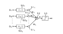
付加条件判定器21は、CM候補テーブル20aを入力とし、CM候補の特徴量を、閾値関数などにより非線型にパラメータ変換した後、荷重加算することでCM候補に対するスコアRを算出し、Rが所定の閾値以上である場合には有力CM候補と判定する。付加条件判定器21は、これらスコアRとスコア判定結果ZをCM候補テーブル20aに追加記述し、CM候補テーブル21aとして出力する。
【0227】
図22には、付加条件判定器21の概略構成を示す。
【0228】
この図22において、CM候補テーブル21aの各特徴量Q1〜QLは、それぞれ対応する関数演算器501〜50Lに送られ、それぞれ対応するパラメータ変換関数H1()〜HL()による変換演算が施された後、さらにそれぞれ対応する重み付け器511〜51Lにより重みW1〜WLとの積がとられる。各重み付け器511〜51Lにより重み付けがなされた後の特徴量は、総和加算器52での総和加算によりスコアRが算出される。この総和加算器52から出力されたスコアRは、スコア判定器53にて所定の閾値と比較され、スコアRが所定の閾値以上である場合には有力CM候補である旨を示す判定結果が出力される。なお、スコア判定器53によるスコア判定により所定の閾値未満であると判定されたCM候補は、テーブルから消去される。
【0229】
より具体的に説明すると、当該付加条件判定器21におけるスコア算出演算は、式(33)に従って行われる。
【0230】
【数18】
ただし、Hl()は各特徴量に対して予め定めるパラメータ変換関数、Wlは予め決定しておく荷重、Lは特徴量数(=11)である。なお、lは1〜11のうちの任意の数である。
【0232】
ここで、各関数演算器501〜50Lにおけるパラメータ変換関数Hl()は、最も簡単には矩形関数でよい。すなわち例えば、図23の(b)に示すような矩形関数Rect(x;t1,t2)を用い、予め各特徴量について決定しておく標準値の下上限値をt1l,t2lとし、式(34)により例えばQ1が標準値の範囲内ならば1、範囲外ならば0となるようにする。
【0233】
Hl(Ql)=Rect(Ql;t1,t2) (34)
なお、前記境界付近で滑らかに0から1、1から0への推移させるようにする場合には、例えば式(35)のような、シグモイド関数Sigm(x;t1,t2)を用いることもできる。
【0234】
【数19】
図23の(c)にはその概形を示す。ただし、σ1l,σ2lは推移の程度を表わす定数であり、予め特徴量の分布などに基づき決定しておく。
【0236】
また、上記各重み付け器511〜51Lによる加算荷重Wlは、予め特徴量の統計的性質に基づき人為的に決定しておくこともできるが、既知の学習サンプルに対して、ニューラルネットワーク(例えば中川著「パターン情報処理」丸善(1999)などに詳説)の要領で学習することで、自動的に荷重を決定することも可能である。なお、lは1〜11のうちの任意の数である。
【0237】
さらに、上記判定器53におけるスコア判定は、式(36)のように、スコアRの閾値処理により行う。
【0238】
Z=Unit(R−tr) (36)
ただし、Unit(x)は、図23の(a)に示すように、x>0で1、x<0で0となる単位ステップ関数であり、trは予め定めるか或いは学習により自動的に決まる判定閾値である。
【0239】
次に、ルール判定器22は、上記付加条件判定器21でのスコア判定により得られたCM候補テーブル21aを入力とし、後述するような所定のルール判定によりm最終的なCM検出出力4aとしてCM開始時刻と長さを出力する。すなわち、当該ルール判定器22では、同一時刻に複数のCM候補があった場合(以下、競合関係という)に、どちらがよりCMとして確からしいかをルール処理により判定する。
【0240】
以下、ルール判定器22の動作を図24のフローチャートを用いて説明する。
【0241】
先ず、ルール判定器22は、ステップS70として、CM候補テーブルより、判定するべくCM候補を選択する。これは、CM候補テーブル中で最古の候補であり、予め設定された時間T4が経過したものから順に行う。T4は、数個のCMが十分含まれる程度の時間長であり、例えば150秒間とする。
【0242】
続いて、ルール判定器22は、ステップS71として、選択したCM候補の区間中(TsからTs+Twまでの間)に、他のCM候補が存在するかどうか、CM候補テーブル中を検索する。このステップS71において、存在しないと判定した場合(No)、このCM候補はCM検出出力として出力され、CM候補テーブルより消去される。
【0243】
一方、ステップS71において、存在すると判定した場合(Yes)、それらは競合関係にあるとして、ステップS72にて先ず最小長さ優先ルールが適用される。ここで、最小長さ優先ルールは、ある時区間が、複数の長さの異なるCM候補の組み合わせにより構成され得る場合、より短いCM候補で構成されている方を優先するというルールである。すなわち、例えば30秒という時区間に対して、1つの30秒CMという可能性と、2つの15秒CMの組み合わせという可能性の、両方が同時に候補として存在する場合には、15秒CMを選択し、30秒CMを棄却するというルールである。
【0244】
図25を用いて、この最小長さ優先ルールの一例を説明する。
【0245】
なおこの例には、図25の(a)のように、実際には4つのCM1〜CM4が連続して放送されている区間に対し、図25の(b)中A〜Hで示すような8つの候補がCM候補テーブルに存在する場合が示されている。
【0246】
先ず、図25の(c)に示すように、AのCM候補が判定中であるとすると、この候補Aと競合する候補はEとHである。しかしながら、Eの区間はAとBで記述でき、また、Hの区間はAとBとCとD等で記述できることから、それぞれ棄却され、Aが採用される。続いて、図25の(d)に示すように、Bが判定中となったときには、Fが競合相手となる(このとき、E、HはAの判定により棄却済みとなっている)が、Fの区間はBとCで記述できることから棄却され、Bが採用される。同様に、図25の(e)に示すように、Cが判定中の場合には、Gが競合相手となるが、Gの区間はCとDで記述されることから棄却され、Cが採用される。最後に、図25の(f)に示すように、Dが判定されるときには、すでに競合相手は存在しないので、そもそもこのルールを適用する必要はなく、当該Dがそのまま採用される。
【0247】
以上により、この時区間からは、CM候補としてA,B,C,Dが選択されることとなる。このルールが適用できない競合関係については、そのままCM候補テーブルに残してこの処理を終了する。
【0248】
図24に戻り、ステップS72のルール判定の後、ルール判定器22の処理は、ステップS73に進む。ステップS73に進むと、ルール判定器22は、最小長さ優先ルールを適用した結果、判定中のCMが棄却されたか否か判断する。このステップS73において、判定中のCMが棄却されと判断した場合(Yes)、ルール判定器22は、その候補をCM候補テーブルから消去し、ステップS70に戻る。一方、ステップS73において、棄却されていないと判断した場合(No)、ルール判定器22では、ステップS74において、再び判定中のCM候補の区間中に他のCM候補が存在するかどうか、テーブル中を検索する。
【0249】
このステップS74において他のCM候補が存在しないと判定した場合(No)、ルール判定器22では、ステップS80において判定中のCM候補をCM検出出力から出力し、CM候補テーブルから消去する。一方、ステップS74にて存在すると判断した場合(Yes)、ルール判定器22の処理は、ステップS75に進む。
【0250】
ステップS75に進むと、ルール判定器22は、隣接優先ルールを適用する。ここで、隣接優先ルールとは、複数のCM候補が競合関係にある場合、それぞれ直前又は直後に隣接するCM候補を検索し、それが存在する方を優先するというルールである。
【0251】
図26を用いて、当該隣接優先ルールについて説明する。
【0252】
なおこの例には、図26の(a)のように、実際には4つのCM11〜CM14が連続して放送されている区間に対し、図26の(b)中I〜Nで示すような6つの候補が存在する場合が示されている。また、この例の場合、候補M及びNは、偶然CM中にカットチェンジや小音量区間が存在したために候補となっているが、このような候補は、実際には誤った区間であるとはいえ、内容的にはCMを含んでいるため、CMらしさを判定する付加条件のスコア判定によっても、棄却されない場合があるものである。
【0253】
このような例において、先ず、図26の(c)に示すように、最古のIが判定される候補となる。当該Iと競合するものとしてMがあるが、Iには隣接する候補Jが存在するのに対し、Mには隣接する候補がないため、Iを採用し、Mを棄却する。次に、図26の(d)に示すように、Jが判定される候補となった場合、Jと競合する候補としてNがあるが、Jには隣接する候補I、Kが存在するのに対し、Nには存在しないため、Jが採用されNが棄却される。次に、図26の(e),(f)に示すように、残りの候補K、Lには、既に競合する候補がなくなるため、このルールは適用されず、これらK、Lがそのまま採用される。
【0254】
以上により、この図26に例示した区間からは、I,J,K,LがCM候補として選択されることとなる。
【0255】
なお、競合関係の候補のいずれにも隣接候補が無い場合、及び複数の候補にそれぞれ隣接候補がある場合には、それらはどちらも棄却されず、CM候補テーブルに残される。
【0256】
図24に戻り、ステップS75の処理後、ルール判定器22の処理は、ステップS76に進む。ステップS76に進むと、ルール判定器22は、隣接優先ルールを適用の結果、判定中のCMが棄却されたか否か判断する。このステップS76において、判定中のCMが棄却されたと判断した場合(Yes)、ルール判定器22は、その候補をCM候補テーブルから消去し、ステップS70の処理に戻る。一方、ステップS76において棄却されていない場合(No)、ルール判定器22は、次のステップS77において、再び判定中のCM候補の区間中に、他のCM候補が存在するかどうか、CM候補テーブル中を検索する。
【0257】
このステップS77において、他のCM候補が存在しなと判定された場合(No)、ルール判定器22は、ステップS80において、判定中のCM候補をCM検出出力から出力し、CM候補テーブルから消去する。一方、ステップS77において、他のCM候補が存在すると判定した場合(Yes)、ルール判定器22は、ステップS78において、スコア優先ルールを適用する。ここで、スコア優先ルールとは、上記の各ルールによっても競合関係が解消されない場合、付加条件判定器21により得られた判定スコアRの高い候補を優先するというルールである。このスコア優先ルールは、対象となる競合関係が解消するまで繰り返し適用する。
【0258】
図27を用いて、当該スコア優先ルールについて説明する。
【0259】
なおこの例には、図27の(a)のように、実際には4つのCM21〜CM24が連続して放送されている区間に対し、図27の(b)中P〜Wで示すような7つの候補が存在する場合が示されている。
【0260】
この例において、先ず、図27の(c)に示すように、最古のPが判定される候補となるが、この候補PはUと競合関係がある。但し、このときの競合関係は、前記最小長さ優先ルールによっても、また、隣接優先ルールによっても競合が解消されない。
【0261】
したがって、この場合には、これら競合関係にある候補と関連する全ての競合関係を、CM候補テーブル中から検索する。すなわち、この場合は、(P−U)、(U−Q)、(Q−V)、(V−R)、(R−W)、(W−S)という、7候補に対する6つの競合関係が全て関連しているので、スコア優先ルールでは、これら関連する候補の中で最もスコアの高い候補を採用する。この例の場合、判定スコアR(2.0)が最も高いスコアであるため、図27の(d)に示すように、このスコアが採用され、その結果、Rと競合関係にある候補V、Wは棄却される。
【0262】
しかしながら、図27の(e)に示すように、これによっても(P−U)の競合関係は解消されていない。したがって、再びこれらと関連する全ての競合関係を、CM候補テーブル中から検索する。今回は、Vが棄却されたことにより、(P−U)、(U−Q)という、3つの候補が関係する2つの競合関係のみとなる。
【0263】
さらに、これらの候補の中で最もスコアの高い候補Q(1.9)を採用し、図27の(f)に示すように、Qと競合関係にある候補Uを棄却する。
【0264】
以上によって、Pに関係する競合関係はなくなり、Pが採用される。また、U、V、Wは全て棄却され、Q、R、Sが採用されることとなる。
【0265】
なお、もしも、関連する全ての競合関係を検索せず、対象となる競合関係(この例の場合、P,U)のみでスコア優先ルールを適用すると、先ずUが採用され、Pは棄却される。後にUとQとの競合関係により、一時採用されたUもまた棄却されてしまう。このように、ルール判定器22では、偶然の処理順序により候補Pが棄却されるようなことのないよう、関連競合関係の検索を行っている。
【0266】
以上のスコア優先ルールにより、選択された候補に関する競合関係は必ず解消されることになる。
【0267】
図24に戻り、ステップS78の処理後、ルール判定器22の処理は、ステップS79に進む。ステップS79に進むと、ルール判定器22は、スコア優先ルールを適用の結果、判定中の候補が棄却されたか否か判断する。このステップS79において、判定中の候補が棄却されたと判断した場合(Yes)、ルール判定器22は、その候補をCM候補テーブルより消去し、ステップS70に戻る。一方、ステップS79において、棄却されなかった場合、ルール判定器22は、ステップS80のCM検出出力として、開始時刻とその長さを出力し、CM候補テーブルから消去した後、ステップS70に戻る。
【0268】
以上説明したように、本実施の形態の第1の具体例のCM検出部202においては、ほぼ全てのCMが満足する必須条件に基づき、決定論的に番組中からCMの候補を抽出し、CMらしさの指標である付加条件に基づく特徴量の統計論的な評価により候補を選択し、論理条件により候補のオーバーラップ関係を解消することで、精度の高いCM検出を実現している。また、本実施の形態では、例えば現行のアナログTV放送の映像音声録画録音装置を例にとったが、ディジタルTV放送等に適用される場合にも同様のCM検出部202が適用できることは明らかである。また、例えばラジオ放送に適用される場合には、上記CM検出部202から映像信号の処理を担当する部分を省略することで同様の機能が実現できる。
【0269】
次に、本発明の第2の具体例としてのCM検出部202について以下に説明する。
【0270】
図28には、本発明の第2の具体例としてのCM検出部202の詳細な構成を示す。
【0271】
当該第2の具体例のCM検出部202は、前述した付加条件の中でも基本的なもののみを実装するようにしており、前述した1)〜14)の付加条件のうち、11)〜14)に関しては導入しないことで、装置構成を簡略化している(複雑になることを防いでいる)。
【0272】
この第2の具体例のCM検出部202も、図15の例と同様にフロントエンド部とバックエンド部とから構成されている。なお、この図28において、図15の各構成要素と同じ動作を行う部分については、同一の指示符号を付して、それらの説明は省略する。
【0273】
以下、図28の構成において、新たに追加された各構成要素(101,102,103)と、付加条件算出器20において新たに拡張された機能についてのみ説明する。
【0274】
フロントエンド部に設けられた音源識別器101は、ディジタル化及びフレーム化された音声信号2bを入力とし、この音声信号2bの該当フレームに関する音源名を出力する。音源名としては、例えば、音声、音楽、音声と音楽、その他を挙げることができる。なお、入力された音声信号の音源識別を実現する技術としては、例えば、河地、他による、「VQ歪みに基づく放送音の自動分類」信学技報、DSP97‐95/SP97‐50、43/48(1998)に記載された技術や、南、他による、「音情報を用いた映像インデクシングとその応用」信学論、Vo1.J81‐D‐II、No.3,529/537(1998)に記載された技術、安部による、特願平11−190693号の明細書及び図面に記載された技術などがあり、これらを利用することができる。
【0275】
この音源識別器101により識別された各音源名は、例えば音声=1、音楽=2、などのように、各フレーム毎に適切に数値化され、特徴量U[n]として特徴量バッファ18に入力される。
【0276】
フロントエンド部に設けられた番組ジャンルデータ又は番組ジャンル識別器102は、現在処理している番組のジャンル名を出力するものである。番組ジャンルは、例えば、ニュース、ドラマ、野球、サッカーなどである。番組ジャンルデータは、テレビ番組表などから入力してもよく、また近年ではインターネット等を通じて自動的に取得することもできる。または、外部情報に頼らず音声及び映像信号から番組ジャンルを識別する装置を用いることも可能である。なお、音声及び映像信号から番組ジャンルを識別する技術としては、例えば安部による、特願平11−190693号の明細書及び図面に記載された技術などを利用することができる。
【0277】
この番組ジャンルデータ又は番組ジャンル識別器102により分類された番組ジャンル名は、例えばニュース=1、ドラマ=2、などのように、各フレーム毎に適切に数値化され、特徴量W[n]として特徴量バッファ18に入力される。
【0278】
フロントエンド部のその他の各構成要素は、図15の例と全く同じである。
【0279】
この第2の具体例の場合、フロントエンド部に、上記音源識別器101と番組ジャンルデータ又は番組ジャンル識別器102を設け、これらにより得られた各特徴量U[n]とW[n]を特徴量バッファ18に蓄積することで、当該特徴量バッファ18においては、式(21)に示した特徴量G[n]が、式(37)のように拡張されることになる。
【0280】
【0281】
また、バックエンド部のCM確率データベース103には、予め、時間帯に応じたCMの放送確率、及び、番組ジャンルと経過時間に応じたCMの放送確率をデータとして蓄積してある。このCM確率データベース103からは、現在時刻に応じてそれらの確率が読み出され、付加条件算出器20に入力するようになされている。なお、これらの確率のデータは、実際の放送を元に統計をとることで作成することができる。
【0282】
この第2の具体例の場合の付加条件算出器20は、前述の特徴量Q1からQ11に加え、次の特徴量Q12からQ15の演算を行うよう拡張される。
【0283】
ここで、特徴量Q12は、CM候補区間中に、音声区間があったどうかを検出して求められるものである。音声の有無を表す特徴量Q12は、式(38)に従って検出される。
【0284】
【数20】
特徴量Q13は、上記音声の有無と同様に、CM候補区間中に、音楽区間があったどうかを検出して求められるものである。この音楽の有無を表す特徴量Q13は、式(39)に従って検出される。
【0286】
【数21】
特徴量Q14は、現在時刻に応じたCMの発生確率(時間帯確率)である。付加条件算出器20では、CM確率データベース103より提供されるCMの放送確率を、そのまま特徴量Q14に代入する。
【0288】
特徴量Q15は、番組ジャンル及びその番組の開始からの経過時間に従うCMの放送確率(番組ジャンル確率)である。付加条件算出器20では、CM確率データベース103より提供されるCMの放送確率を、そのまま特徴量Q15に代入する。
【0289】
付加条件判定器21以降は、変数としての特徴量Q12〜Q15が拡張されるだけであり、前述の図15のCM検出部202の場合と同様であるため、説明を省略する。
【0290】
この場合のCM検出部202においては、以上の拡張により、放送信号の音源に応じたCM検出を行うことができ、また、現在時間に応じたCM検出を行うこと、さらに、番組ジャンルに応じたCM検出を行うことが可能となる。
【0291】
次に、図30には、上述した図15や図28に示したCM検出部202を実装する場合のハードウェア構成の一例を示す。
【0292】
この図19において、A/D変換器40は、前記図15や図28のA/D変換器10及び13の機能を備え、メモリ41は、前記フレームメモリ11及び音声信号バッファ14の機能を備えている。
【0293】
A/VプロセッサまたはDSP(ディジタルシグナルプロセッサ)42は、前記カットチェンジ検出器112、振幅検出器15、相関検出器16、スペクトル検出器17、音源識別器101等の機能を備え、メモリ43は、前記特徴量バッファ18の機能を備えている。
【0294】
プロセッサ44は、前記CM候補検出器19、付加情報算出器20、付加条件判定器21、ルール判定器22、CM確率データベース103等の機能を備えている。
【0295】
前記動作制御部23の機能については、A/VプロセッサまたはDSP(ディジタルシグナルプロセッサ)42か、或いは、プロセッサ44が備えることができる。
【0296】
【発明の効果】
本発明においては、入力信号から第1の信号区間を検出し、その第1の信号区間の検出結果に基づいて入力信号から第1の信号部分を抽出して記録することにより、例えば、入力信号としての放送信号から、第1の信号としてのCM部分を高精度に検出できると共に、そのCMの蓄積、閲覧、視聴、検索等も可能となる。
【図面の簡単な説明】
【図1】本発明実施の形態の放送信号処理装置の全体構成図である。
【図2】CM検出部、CM抽出部、CM記録部のサブセットの構成図である。
【図3】図2のサブセットにおける動作の流れを示すフローチャートである。
【図4】入力音声信号及び映像信号の離散化とフレームの説明に用いる図である。
【図5】CM検出部、CM抽出部、CM特徴抽出部、CM記録部のサブセットの構成図である。
【図6】図5のサブセットにおける動作の流れを示すフローチャートである。
【図7】表示部の表示画面例を示す図である。
【図8】CM記録部、CM索引生成部、CM閲覧部、CM選択部のサブセットの構成図である。
【図9】図8のサブセットにおける動作の流れを示すフローチャートである。
【図10】CM記録部、特徴比較部のサブセットの構成図である。
【図11】図10のサブセットにおける動作の流れを示すフローチャートである。
【図12】表示部の他の表示画面例(検索アイコンを表示する例)を示す図である。
【図13】CM記録部、特徴比較部、CM索引生成部、CM閲覧部、CM選択部のサブセットの構成図である。
【図14】図13のサブセットにおける動作の流れを示すフローチャートである。
【図15】第1の具体例のCM検出部の詳細な構成図である。
【図16】CM検出部のフロントエンド部における映像信号処理の流れを示すフローチャートである。
【図17】CM検出部のフロントエンド部における音声信号処理の流れを示すフローチャートである。
【図18】CM検出部のCM候補検出器における動作の流れを示すフローチャートである。
【図19】必須条件の算出例の説明に用いる図である。
【図20】第1の具体例のCM検出部におけるCM候補テーブルを示す図である。
【図21】CM検出部の付加条件算出器における特徴量の算出例の説明に用いる図である。
【図22】付加条件算出器の構成図である。
【図23】スコア算出演算の際の単位ステップ関数、矩形関数、シグモイド型関数の説明に用いる図である。
【図24】ルール判定器の動作の流れを示すフローチャートである。
【図25】最小長さ優先ルールの説明に用いる図である。
【図26】隣接優先ルールの説明に用いる図である。
【図27】スコア優先ルールの説明に用いる図である。
【図28】第2の具体例のCM検出部の詳細な構成図である。
【図29】第2の具体例のCM検出部におけるCM候補テーブル(拡張部分のみ)を示す図である。
【図30】CM検出部を実装する場合の一例としてのハードウェア構成図である。
【符号の説明】
201 CM抽出部、 202 CM検出部、 203 CM特徴抽出部、 204 特徴比較部、 205 CM記録部、 206 CM索引生成部、 207 CM選択部、 208 CM閲覧部、 801 表示プロセッサ、 802 表示部、 810 CM索引画像又は映像、 811 CM再生アイコン、812 音声再生アイコン、 813 前ページアイコン、 814 次ページアイコン、 815 検索アイコン[0001]
BACKGROUND OF THE INVENTION
The present invention is applied to, for example, a video / audio recording / reproducing apparatus, and more particularly to a signal processing apparatus and method suitable for storing, viewing, viewing, searching, and the like of commercial messages added to a television broadcast. It is.
[0002]
[Prior art]
Public broadcasts such as television broadcasts and radio broadcasts are broadcast by inserting commercial messages (hereinafter simply referred to as CMs) from companies and organizations into the main part of the program, except for some pay broadcasts. Often done.
[0003]
While viewers may feel that commercials are unnecessary while watching the main program, CMs are a direct source of information on unknown products, commercials with famous actors, and commercials with stories. In many cases, the CM itself is a viewing target as a work.
[0004]
However, for a program, for example, the broadcast time can be known in advance using a program guide, etc., whereas for a CM, it is generally impossible to know in advance when the broadcast will be broadcast, so a specific CM is required. It is difficult to watch accordingly. Therefore, for example, if all CMs broadcast within a predetermined time are accumulated and can be browsed, viewed, searched, etc. as necessary, it is possible to respond to the various requests as described above with high convenience. Conceivable.
[0005]
[Problems to be solved by the invention]
Conventionally, as a technique for detecting a CM from a broadcast signal, for example, JP-A-8-317342, JP-A-3-15886, JP-A-3-2622872 and the like skip the CM for viewing. The technology is public. However, although these techniques can remove CMs, they cannot store, browse, view, search, etc. CMs.
[0006]
Japanese Laid-Open Patent Publication No. 10-224724 discloses a technique for detecting and accumulating information associated with a CM and reproducing the same commercial only once. However, even if this technology is used, it does not satisfy the demands for storage, browsing, viewing, searching, etc. of the CM, and the CM section that is often broadcast in stereo mode is not distinguished from the stereo program section. The range that can be done is very limited.
[0007]
In view of the above, it is desired to be able to detect a CM portion from a broadcast signal with high accuracy and to enable storage, browsing, viewing, searching, and the like of the CM.
[0008]
Therefore, the present invention has been made in view of the above situation. For example, the CM portion can be detected from the broadcast signal with high accuracy, and the CM can be stored, viewed, viewed, searched, and the like. An object of the present invention is to provide a signal processing apparatus and method.
[0009]
[Means for Solving the Problems]
The signal processing apparatus according to the present invention includes an input signal in which at least a first signal section and other signal sections exist in a time division manner.Based on a characteristic pattern of a signal having a predetermined time interval, candidate section detecting means for detecting a candidate section of the first signal, and the input signal in or around the candidate section, the likelihood of the first signal A feature amount extracting means for extracting a feature amount representingFirst signalofDetect intervalsRuDetection means;A determination unit that performs rule determination on the first signal interval detected by the detection unit, and determines the first signal interval;Of the first signal intervalJudgmentBased on the result, there is provided first signal extraction means for extracting a signal in the first signal section from the input signal, and recording means for recording the extracted first signal.The input signal is composed of video and audio signals, the first signal section is a commercial message (CM) section, and the candidate section is a frame section of a predetermined length that satisfies the volume condition and the video condition. In the rule determination used by the determination means, the minimum length priority rule is used when another CM candidate exists in the CM candidate section, and another CM candidate is applied after the minimum length priority rule is applied. In the determination, the adjacency priority rule is used, and the score priority rule is used when another CM candidate exists after the application of the adjacency priority rule.
[0010]
Further, the signal processing method of the present invention is based on an input signal in which at least a first signal section and other signal sections exist in a time division manner.A candidate section detecting step of detecting a candidate section of the first signal based on a characteristic pattern of a signal having a predetermined time interval, and an input signal in the candidate section or an input signal before or after the candidate section. A feature amount extraction step for extracting a feature amount representingFirst signalofDetect intervalA determination step of performing a rule determination on the first signal interval detected by the detection step, and determining a first signal interval;Of the first signal intervalJudgmentBased on the result, the signal of the first signal section is extracted from the input signal.A first signal extraction step to:Record the extracted first signalThe input signal is composed of video and audio signals, the first signal section is a commercial message (CM) section, and the candidate section is a predetermined condition that satisfies the volume condition and the video condition. The rule determination used in the determination step is a frame segment of length, and when there is another CM candidate in the CM candidate segment, the minimum length priority rule is used, and the minimum length priority rule is applied. When another CM candidate is present later, the adjacency priority rule is used, and when another CM candidate exists after the adjacency priority rule is applied, the score priority rule is used.
[0011]
That is, according to the present invention, it is possible to separate and organize the first signal from the input signal by detecting and recording the first signal from the input signal. In addition, according to the present invention, by extracting a feature amount characterizing the detected first signal and recording it together with the first signal, for example, browsing, removing, searching, etc. of the first signal can be facilitated. It becomes feasible. Further, according to the present invention, index information representative of the first signal is extracted and displayed, so that browsing and searching of the first signal can be easily realized. Furthermore, according to the present invention, the same signal is removed from the recorded first signal, for example, to improve the recording efficiency, and the same signal can be browsed or searched a plurality of times during browsing, thereby eliminating waste. be able to. Furthermore, according to the present invention, various searches are possible by detecting the first signal partially identical or similar.
[0012]
DETAILED DESCRIPTION OF THE INVENTION
Hereinafter, preferred embodiments of the present invention will be described with reference to the drawings.
[0013]
FIG. 1 shows a schematic configuration of a broadcast signal processing apparatus according to the first embodiment of the present invention.
[0014]
The broadcast signal processing apparatus shown in FIG. 1 receives a signal 200a composed of a video signal, an audio signal, a control signal, a program guide signal, and the like. This input signal 200a is received through terrestrial broadcast, satellite broadcast, cable broadcast, telephone line, or the like, or is reproduced after being recorded in another recording device (not shown). Here, the video signal and the audio signal are signals constituting the main part of the broadcast signal including the main program and the CM part. The control signal includes information such as the broadcast mode, broadcast time, broadcast frequency or channel, and the program guide signal is related to the video signal or audio signal received by digital broadcasting or a telephone line. Contains some data. In the following description, it is assumed that these are signals of a single broadcast program, but signals of a plurality of channels may be input simultaneously.
[0015]
In the broadcast signal processing apparatus shown in FIG. 1, the
[0016]
Based on the CM detection signal 202a supplied from the
[0017]
The
[0018]
Here, FIG. 2 shows a subset obtained by extracting only the above-described
[0019]
In FIG. 3, first, in the subset of FIG. 2, when the video signal / audio signal / control signal / program guide signal as the input signal 200a is sequentially input in step S220, the input signal 200a is input in step S221. The data is stored in the temporary storage device that is internal or external to the
[0020]
At the same time, in the subset of FIG. 2, the
[0021]
When the processing proceeds to step S223, the
[0022]
Thereafter, in the subset of FIG. 2, when the process proceeds to step S225, the signal temporarily stored in the
[0023]
Returning to FIG. 1, the CM
[0024]
Here, as the feature quantity characterizing the CM, the following amplitude feature quantity, spectral feature quantity, linear prediction coefficient, luminance histogram and color histogram, average luminance, luminance difference energy, cut, which are extracted from the video signal and the audio signal are cut. Some or all of the physical quantities such as the number of times of change and time can be used. Since these feature amounts are the same pattern in the same CM and different patterns in different CMs, it can be said that they characterize the CM.
[0025]
In the following description, it is assumed that the input audio signal and the video signal are discretized, and the input audio signal is represented by S [m] shown in FIG. 4B, and m = 0, 1,. The discrete time is represented, and M represents the discrete time corresponding to the processing frame. Also, I [x, y; l] shown in FIG. 4A represents the input video signal, l = 0, 1,..., L−1 represents each video frame of the input video, and L represents the processing frame. , X-1 is the horizontal pixel number, X is the horizontal video size, y = 0,..., Y-1 is the vertical pixel number. , Y represents the video size in the vertical direction. The processing frame is a processing unit of a predetermined time length, and is set to 250 ms, for example. Further, as shown in FIG. 4C, the number of frames corresponding to the CM section length is represented by N.
[0026]
Hereinafter, each feature amount will be described.
[0027]
First, the amplitude feature quantity A [n] of the processing frame n is the mean square amplitude value of the audio signal in the frame n and is obtained as shown in Expression (1).
[0028]
[Expression 1]
A vector obtained by summing up all the frames in the CM section is represented by A = (A [0], A [1],..., A [N−1]).
[0030]
Next, the spectral feature value F [k; n] of the processing frame n is an average spectrum in the frame n and is obtained as shown in Expression (2).
[0031]
[Expression 2]
Here, k = 0,..., K is a number representing a discretized frequency, and K represents the highest frequency of interest. This calculation is implemented using FFT, linear prediction analysis, or the like. The frequency discretization step can be made linear, for example, every 1 kHz, or non-linear, eg, every octave, by re-discretizing k in Equation (2). A vector in which all the frames in the CM section are collected is represented by F = (F [0; 0], F [1; 0],..., F [K-1; N-1]).
[0033]
Next, the linear prediction coefficient P [k; n] in the processing frame n is calculated using an LPC algorithm shown in, for example, Linear Prediction of Speech (Markel et al., Springer-Verag, 1978). k = 0,..., K−1 are numbers representing linear prediction coefficients, and K is a prediction order. Further, a vector in which all the wallets in the CM section are collected is represented by P = (P [0; 0], P [1; 0],..., P [K-1; N-1]).
[0034]
Next, the luminance histogram H of the processing frame n1[q; n] is a histogram of the luminance of the video signal in frame n. Here, q = 0,..., Q−1 is an index number representing a cell for luminance, and Q is the number of cells of bis and gram.
[0035]
Color histogram H of processing frame nC[q; n] is an intensity histogram for each color of the signal in frame n. Here, q = 0,..., Q−1 are index numbers representing the color and intensity cells, and Q is the number of cells in the histogram.
[0036]
A vector in which the luminance histogram and the color histogram are respectively collected for all the frames in the CM section is represented as HI= (HI[0; 0], HI[1; 0],…, HI[Q-1; N-1]) and HC= (HC[0; 0], HC[1; 0],…, HC[Q-1; N-1]).
[0037]
Next, the average luminance B [n] of the processing frame n is the average luminance of the video signal in the frame n and is obtained as shown in Expression (3).
[0038]
[Equation 3]
A vector in which all the frames in the CM section are collected is represented by B = (B [0], B [1],..., B [N−1]).
[0040]
Next, the luminance difference energy D [n] of the processing frame n is the inter-pixel difference energy of the adjacent video frame, and is obtained by, for example, Expression (4).
[0041]
[Expression 4]
A vector obtained by summing up all the frames in the CM section is represented by D = (D [0], D [1],..., D [N−1]). In this calculation, instead of the inter-pixel difference, an average luminance difference of the entire screen or an inter-block difference such as 8 × 8 pixels or 16 × 16 pixels in the horizontal × vertical direction can be used.
[0043]
Next, the number of cut changes C [n] of the processing frame n is the number of frames in which the pixel difference energy between adjacent video frames exceeds a predetermined threshold in the processing frame n, and is obtained by Expression (5).
[0044]
[Equation 5]
However, Countb a(f) is a function representing the number of times that the evaluation formula f is satisfied in the interval from a to b, and DthsdIs a predetermined threshold for the luminance difference energy. A vector obtained by summing up all the processing frames in the CM section is represented by C = (C [0], C [1],..., C [N−1]).
[0046]
The cut change time can be obtained as a frame number n where C [n]> 0, and the number of cut changes in the entire CM section can be obtained as the sum of C [n].
[0047]
The CM
[0048]
V = {A, F, P, HI, HC, B, D, C} (6)
The feature vector V can also be expressed as in equation (7).
[0049]
V = {V [0], V [1],..., V [N-1]} (7) where V [n] is each feature quantity in the processing frame n as shown in Expression (8). Are collected as a vector.
[0050]
V = {A [n], F [k; n], P [k; n], HI[n], HC[n], B [n], D [n], C [n]} (8) The above-described feature amount extracted by the CM
[0051]
Here, FIG. 5 shows a subset obtained by extracting only the above-described
[0052]
In the subset of FIG. 5, in the subset of FIG. 5, when the process proceeds to step S233 after the process in step S220, the video signal / audio signal / control signal / program guide signal as the input signal 200a is sequentially input. In step S231, the input signal 200a is stored in the temporary storage device that is internally or externally attached to the CM
[0053]
At the same time, the
[0054]
In the subset of FIG. 5, when the processing proceeds to step S232, the CM
[0055]
Thereafter, in the subset of FIG. 5, when the process proceeds to step S235, the signal temporarily stored in the CM
[0056]
Returning to FIG. 1, the CM partial signal (video signal / audio signal / control signal / program guide signal) 201a corresponding to the CM section recorded in the
[0057]
Based on the CM partial signal 201a and the feature amount 203a supplied from the
[0058]
Here, as the CM index information 206a, for example, information indicating the following start point image, cut point image, cut point video, start part sound, end part sound and the like is used.
[0059]
Hereinafter, the CM index information 206a will be described.
[0060]
First, the start point image is an image of the start point of the CM section, and this start point image is set as one piece of index information.
[0061]
The cut point image is an image of each cut point in the CM section, and this cut point image is one of the index information. Since the cut point is a processing frame having a feature amount C [n] larger than 0, an image at that time is used. Usually, since there are a plurality of cut points in one CM, one image is selected based on a predetermined criterion such as the first or last cut point.
[0062]
The cut point video is a video obtained by connecting images of each cut point in the CM section and time-sequentially, and this cut point video is used as index information. Usually, since there are a plurality of cut points in one CM, a new short video is generated by connecting all the images of the cut points.
[0063]
The start part voice is a voice for a predetermined time of the first part of the CM section, for example, 2 seconds, and this start part voice is one of the index information. In particular, since there is a case where a characteristic voice exists as an introduction of a short CM at the start of the voice, it is useful to use this as a CM index.
[0064]
The end part voice is a voice for a predetermined time of the first part of the CM section, for example, 2 seconds, and this end part voice is used as one of the index information. In particular, since there are many product names or images or sounds commonly used by companies or organizations at the end of audio, it is useful to use this as an index for CM.
[0065]
CM partial signal 201a from the
[0066]
The
[0067]
Further, the user selection information 207 a generated by the
[0068]
The
[0069]
The operation of the
[0070]
First, as shown in FIG. 7, the
[0071]
When the user selection information 207a is received from the
[0072]
In the state where the display as shown in FIG. 7 is being made, for example, when the
[0073]
Here, FIG. 8 shows a subset in which only the
[0074]
In FIG. 9, the
[0075]
Next, as step S243, the
[0076]
Here, if the user selection information 207a generated by the
[0077]
If the user selection information 207a specifies the
[0078]
If the user selection information 207a specifies the
[0079]
If the user selection information 207a specifies the
[0080]
If the user selection information 207a specifies the
[0081]
This is repeated below.
[0082]
Returning to FIG. 1, the feature vector V of each CM recorded in the
[0083]
The
[0084]
First, the evaluation function J (i, j) is calculated as shown in Equation (9).
[0085]
[Formula 6]
Subsequently, J (i, j) is changed to a predetermined threshold JthsdCompared to JthsdIf it is less than the same CM,thsdIf it is larger, it is judged as a different CM. Such comparison is performed for all CMs recorded in the
[0087]
Here, FIG. 10 shows a subset in which only the
[0088]
In FIG. 11, the
[0089]
Subsequently, the
[0090]
In step S254, the
[0091]
Next, in the broadcast signal processing apparatus according to the embodiment of the present invention, when a search icon is further added to the above-described display screen example of the
[0092]
That is, when the
[0093]
When the user selection information 207a is supplied to the
[0094]
That is, in the
[0095]
In this comparison, first, the evaluation function J ′ (i, j) of the CM partial section is calculated according to the equation (10).
[0096]
[Expression 7]
However, N in the formulasIs the first processing frame number of the CM partial section to be compared, NeIs the last processing frame number of the CM partial section to be compared.
[0098]
Subsequently, the
[0099]
In this comparison, even if the CMs are different, for example, a common video / audio signal is inserted into a CM provided by the same provider, so that viewers have a common feeling. There are many cases that have been created. Also, a common video / audio signal for this purpose is often about 1 second. Thus, for example, Ne= N-1 is the last frame number of the CM section, and NsIf one CM is designated by making the processing frame one second before, it becomes possible to search all CMs provided by the same company.
[0100]
In addition, the evaluation function J ′ (i, j) at the time of comparing feature quantities can be set as shown in Expression (11).
[0101]
[Equation 8]
However, NwIs a section length for performing a match search, s is an index number for shifting the partial match search section from the beginning to the end of the CM section, and Mins() Represents the smallest value of all s. In this case, the feature amount H related to the video in the vector V [n].I[n], HCExcept for [n], B [n], D [n], and C [n], it is also possible to use only the feature values A [n], F [k; n], and P [k; n] related to speech. It is valid.
[0103]
By using such a function, it is possible to search for a matching CM in any part of the CM. According to this, for example, a CM using the same music as background music can be searched. For example, if the same product or company or group offers several continuity commercials, the function is a continuation because the same background music is often used to make the viewer feel common. It becomes an effective evaluation function when searching for a CM or the like made with the property.
[0104]
Note that the evaluation functions J (i, j) and J ′ (i, j) may be referred to as the similarity between two CMs.
[0105]
The CM video and audio signals retrieved from the
[0106]
At this time, the
[0107]
As a result, the
[0108]
FIG. 13 shows a
[0109]
In FIG. 14, when the user instruction standby state in step S244 in the flowchart of FIG. 9 is in the user selection information 207a, for example, specifies the CM
[0110]
Subsequently, the
[0111]
In step S264, the
[0112]
In the present embodiment, the above-described removal of the same CM is not performed, all the CMs are accumulated, and the search is performed by matching all CM sections, so that the number of times the same CM is broadcast and its time It is also possible to search.
[0113]
As described above, according to the broadcast signal processing apparatus of the present embodiment, it is possible to extract and store only the CM portion from the broadcast signal, thereby, for example, without recording the program portion, It is possible to provide a database device that stores only the CM portion.
[0114]
Further, according to the broadcast signal processing apparatus of the present embodiment, it is possible to extract only the CM portion from the broadcast signal, extract the feature quantity characterizing the CM portion, and accumulate them, for example, It is possible to provide a database device that stores only the CM portion and its feature amount without recording the program portion. These feature quantities are particularly useful for the same CM search, similar CM search, and the like.
[0115]
In addition, according to the broadcast signal processing apparatus of the present embodiment, it is possible to display and browse the CMs accumulated as described above, whereby the viewer (user) can list the accumulated CMs. Display, playback and search can be performed. This is useful when searching for and viewing a CM.
[0116]
Further, according to the broadcast signal processing apparatus of the present embodiment, it is possible to remove the same CM from the CMs accumulated as described above, thereby saving the storage capacity and at the same time The trouble of browsing the CM many times can be avoided.
[0117]
In addition, according to the broadcast signal processing apparatus of the present embodiment, it is possible to search for similar CMs, thereby easily searching for CMs of the same product, CMs of the same provider, and the like from the stored CMs. It is possible to display.
[0118]
In addition, according to the broadcast signal processing apparatus of the present embodiment, it is possible to search for a match with the last part of the CM. That is, since the last part of the CM often includes video and audio common to products, companies, organizations, etc., this makes it possible to easily search and display CMs of the same product or provider.
[0119]
Furthermore, according to the broadcast signal processing apparatus of the present embodiment, it is possible to search for a CM with matching background music. That is, since the same background music is often used for CMs created by the same product or provider with continuity, it is possible to search and display CMs created with continuity.
[0120]
Finally, according to the broadcast signal processing apparatus of the present embodiment, it is possible to measure the time and number of times that the same CM has been broadcast. This is an effective device for the purpose of, for example, the creator of the CM comparing the broadcast schedule with the actual broadcast.
[0121]
Next, details of the
[0122]
Hereinafter, the principle when the
[0123]
In general, a CM broadcasted on TV is produced based on a standard designated by a broadcaster, so that “time length (time of one CM) is limited to a very small number of types”. For example, in Japan, almost all commercials except for special cases are produced with lengths of 15 seconds, 30 seconds, and 60 seconds.
[0124]
In addition, when a CM is broadcast, since the program main part and other CMs that are produced independently are inserted into the TV broadcast stream, the sound level is inevitably reduced before and after each CM (ie, the volume is reduced). And “the video signal is switched”. Here, “the voice level is lowered” is not necessarily synonymous with silence (meaning that there is only a very small noise here). In other words, in reality, there are cases where switching is performed without necessarily being completely silent depending on the timing of switching between the CM and the main part.
[0125]
As described above, the three characteristics of the “specified time length (a few kinds of time lengths)”, “small volume”, and “video switching” for the CM are conditions that almost all the CMs satisfy. In the present invention, the condition based on these three characteristics will be hereinafter referred to as “essential condition”.
[0126]
Therefore, if a signal portion corresponding to the essential condition is detected from a TV broadcast signal, a CM candidate (that is, a signal portion that seems to be a CM) can be detected deterministically with little false rejection. It becomes possible. However, since there are many parts in the main part of the program that meet such an essential condition by chance, there is still a possibility that a part of the main part of the program may be erroneously detected as a CM candidate only by using the above essential condition. .
[0127]
On the other hand, although there are many exceptions compared to the above-mentioned essential conditions, the following characteristics are characteristic of many CMs or exhibit a certain tendency due to the nature of the CMs.
[0128]
1) Before and after the CM (immediately before the CM is started and immediately before the main program is started or resumed after the CM is finished), the audio level is often lower than that in the normal main program.
[0129]
2) In many cases, the section length between the CM and the main part of the program, and between a certain CM and another CM, which is almost silent, is about several hundred milliseconds.
[0130]
3) The voiced section included in the TV broadcast is often shorter by about 100 milliseconds than the specified time length of CM (15 seconds, 30 seconds, 60 seconds, etc.), and is rarely shorter than about 1 second.
[0131]
4) The correlation value between the left channel (L channel) and the right channel (R channel) of the stereo audio signal is often significantly smaller than 1.
[0132]
5) During the CM period, the volume tends to be higher than the main program.
[0133]
6) The CM broadcast mode is often a stereo mode.
[0134]
7) In the CM section, a plurality of CMs are often broadcast continuously.
[0135]
8) During the CM period, the frequency of switching video cuts is often high.
[0136]
9) Conversely, even during the CM period, there is an extremely low frequency of cut switching (for example, CM for still images).
[0137]
10) The sound quality often changes greatly at the boundary between the main program and the CM, or at the boundary between a certain CM and another CM.
[0138]
11) CM often includes voice and music at the same time.
[0139]
12) In the program organization, there is a high probability that a CM will be broadcast around just the hour of every hour.
[0140]
13) Similarly, there is a high probability that a CM will be broadcast around 30 minutes per hour.
[0141]
14) There is a time zone with a high probability that a CM will be broadcast depending on the genre of the program (for example, half time of a soccer broadcast).
[0142]
In the present invention, the conditions based on these characteristics are hereinafter referred to as “additional conditions”. In other words, the additional condition is produced under the restriction that the CM is produced based on the standard, the restriction that the advertising effect is to be improved in a short time, and the restrictions due to the program structure. As a result, it is a condition due to appearing on the TV broadcast signal. Therefore, although this additional condition is not a certain condition that can be handled deterministically, it is an effective condition for evaluating the possibility of being a CM (likeness of CM).
[0143]
Furthermore, in TV broadcasting, it is physically impossible to simultaneously broadcast a plurality of videos and sounds on the same channel. That is, when trying to detect a signal portion (CM candidate) that seems to be a CM from a TV broadcast signal, for example, a plurality of video and audio sections satisfying the additional conditions overlap in the TV broadcast signal. Even if a CM candidate is detected in the overlap section as a result of some processing, at least one of the overlapping video and audio cannot be a correct CM section. In the present invention, a condition based on such characteristics in TV broadcasting is referred to as a “logical condition”.
[0144]
In the present invention, the “essential condition”, “logic condition”, and “additional condition” described above are rationally and effectively used to detect the CM portion from the TV broadcast signal with high accuracy.
[0145]
More specifically, in the present invention, a CM candidate (a signal portion that seems to be a CM) is deterministically extracted from a TV broadcast signal based on an “essential condition”, and a CM based on an “additional condition”. A CM candidate is selected by statistical evaluation of the likelihood (possibility of being a CM), and an overlapping relationship between CM candidates is eliminated by a “logical condition”, thereby realizing highly accurate CM detection.
[0146]
FIG. 15 shows a detailed configuration of the first specific example of the
[0147]
First, the front end portion of FIG. 15 will be described.
[0148]
In FIG. 15, a video signal 2a, an
[0149]
The video signal 2 a is digitized by the A /
[0150]
The cut change detector 12 is based on a video signal for each frame supplied from the
[0151]
That is, the cut change detector 12 obtains a square sum of luminance differences for each pixel between two temporally adjacent frame images stored in the
[0152]
Hereinafter, the detection of the video change frame and the uniform luminance frame in the cut change detector 12 will be described more specifically.
[0153]
Here, the horizontal size of the discretized video signal is X, the vertical size is Y, the vertical and horizontal pixel numbers are x, y, and the video of the nth frame is In(X, y), an image of the (n−1) th frame that is one frame before the nth frame is represented by In-1When expressed as (x, y), the square sum D [n] of the luminance difference for each pixel between the nth frame and the (n−1) th frame is obtained by the equation (12), and The luminance dispersion value V [n] is obtained by Expression (13).
[0154]
[Equation 9]
Further, the detection output C [n] of the cut change detector 12 at this time is expressed by Expression (14).
[0156]
[Expression 10]
However, D in the formulathsdIs a predetermined threshold for the square sum in detecting the video change frame, and VthsdIs a predetermined threshold for the luminance dispersion value when detecting the uniform luminance frame.
[0158]
The detection output C [n] of the cut change detector 12 is sent to the
[0159]
Note that when obtaining the luminance difference between the above-described two frame videos, a memory capable of storing video signals for two frames is required, and a calculation amount for the video signals for two frames is also required. Therefore, for example, instead of simultaneously processing the entire frame image, the frame image is divided into appropriate small blocks and the luminance difference is obtained for each small block, or the luminance difference is calculated for each pixel between the frame images. Rather than obtaining the luminance histogram for each frame image, the difference between the frames of the luminance histogram is obtained, or the average luminance is obtained for each frame image, and the inter-frame difference of the average luminance is calculated. As a result, it is possible to reduce the memory capacity and the calculation amount. On the contrary, when there is a margin in the memory and the calculation amount, for example, the luminance difference or color histogram difference for each color component such as R (red), G (green), and B (blue) component in a color image. By obtaining the above, it is possible to further improve the detection accuracy.
[0160]
Next, the
[0161]
The
[0162]
More specifically, the
[0163]
## EQU11 ##
The mean square amplitude A [n] that is the detection output of the
[0165]
The
[0166]
More specifically, the
[0167]
[Expression 12]
Correlation coefficient A which is the detection output of the correlation detector 16LR[n] and audio signal energy ALL[n], ARREach [n] is sent to the
[0169]
The
[0170]
More specifically, the
[0171]
[Formula 13]
The calculation of Expression (19) is realized using, for example, fast Fourier transform (FFT) or linear prediction analysis (LPC).
[0173]
The short-time discrete spectrum F [k; n], which is the calculation output of the
[0174]
Next, the
[0175]
More specifically, the
[0176]
[Expression 14]
A numerical value B [n] obtained by discretizing the
[0178]
Similarly, the time signal 3a is also converted into a numerical value T [n] that is discretized in accordance with the audio signal processing frame, and is sent to the
[0179]
The
[0180]
G [n] ≡ {C [n], A [n], ALR[n], ALL[n], ARR[n], F [k; n], B [n], T [n]} (21) From the A /
[0181]
First, in FIG. 16 showing the flow of processing for the video signal 2a, the front-end unit converts the video signal 2a for at least one frame digitized by the A /
[0182]
Next, as a process of step S31, the front end unit reads the video signal 2a from the
[0183]
Thereafter, the front end unit stores the detected output C [n] in the
[0184]
On the other hand, in FIG. 17 showing the flow of processing for the
[0185]
The
[0186]
At the same time, the front end unit sends the
[0187]
At the same time, as a process of step S37, the front end unit sends the
[0188]
Further, the front end unit obtains a discretized numeric value B [n] from the
[0189]
The front end portion is obtained from the detection output C [n] from the cut change detector 12, the mean square amplitude A [n] from the
[0190]
Returning to FIG. 15, the back-end unit will be described. In the following description, the number n represents each frame number of the feature amount stored for each frame in the
[0191]
In FIG. 15, the feature amount stored in the
[0192]
The
[0193]
A [0] <Athsd (twenty two)
C [0] = 1 (23)
A [n1] <Athsd, C [n1] = 1 or A [n2] <Athsd, C [n2] = 1 or
A [nThree] <Athsd, C [nThree] = 1 (24)
However, AthsdIs a threshold of a predetermined square amplitude, and n1, N2, NThreeIs the time length defined as the CM length (in this embodiment, the case where there are three types of time lengths of 15 seconds, 30 seconds, and 60 seconds as an example) is used for each frame period. This is the number converted. Since there is an error in the actual broadcast time of the CM, in practice, n1, N2, NThreeEach should have some width.
[0194]
Here, the operation flow of the
[0195]
In FIG. 18, in the
[0196]
When a feature amount for one frame (one sample) is input from the
[0197]
As a result of the determination processes in steps S52 and S53, the mean square amplitude A [0] is a predetermined square amplitude threshold A.thsdIf the above-mentioned essential condition is satisfied, the CM
[0198]
The CM
[0199]
In steps S54 to S56, the same processing as described above is performed for all time lengths, and then the process returns to step S50 to repeat the same processing for the next input.
[0200]
The CM start frame nsAnd n1, N2, NThreeThe mean square amplitude A [n] is the threshold A of the square amplitude from the frame that matches the time condition to the direction of the latest frame.thsdThis is the first frame number exceeding. CM end frame neMeans that the mean square amplitude A [n] is the square amplitude threshold A from the 0th frame toward the past.thsdThis is the last frame number not exceeding. Furthermore, CM start time TsIs the CM start frame number nsTs= T [ns] Is required. Similarly, CM length TwTw= T [ne] -T [ns] Is required.
[0201]
Here, FIG. 19 shows a calculation example of the essential condition. In the term A [n] shown in FIG. 19, “o” is the threshold A of the square amplitude.thsdIndicates a frame with a mean square amplitude less than "x" is the square amplitude threshold AthsdA frame having the above mean square amplitude is shown. In this example, A [0], C [0] and A [n1], C [n1] Satisfies the condition, n1The frame with A [n] = x first on the left is ns, The last frame of A [n] = o consecutive to the right of 0 is neIt becomes.
[0202]
With the above processing, the
[0203]
FIG. 20 shows a configuration example of the CM candidate table. In FIG. 20, the items in the CM candidate table are the start time Ts, Length Tw, And a feature value Q calculated by the
[0204]
The CM candidate table 19 a in which only the start time Ts and the length Tw are described by the
[0205]
The
[0206]
FIG. 21 shows the feature quantity Q in the additional condition calculator 20.1~ Q11An example of calculation is shown.
[0207]
In FIG. 21, the horizontal axis represents the frame number (corresponding to discrete time), (a) in FIG. 21 is the cut change detection output C [n], and (b) in FIG. 21 is the discretized numerical value of the
[0208]
Hereinafter, each feature quantity Q calculated by the
[0209]
Feature Q1Is the previous break length. The previous break length is a low volume section (referred to as the previous break section) immediately before the CM candidate section, that is, A [n] is continuously a predetermined threshold AthsdThe section length BB sandwiched between the alternate long and short dash lines in FIG.1It is.
[0210]
Feature Q2Is the post-break length. The post-break length is a low volume section (referred to as a post-break section) immediately after the CM candidate section, that is, A [n] is a predetermined threshold A continuously.thsdThe section length AB, which is the following time length and is sandwiched by the alternate long and short dash line in FIG.2It is.
[0211]
Feature QThreeIs the minimum amplitude before break. Pre-break minimum amplitude QThreeIs the minimum value of A [n] in the previous break section.
[0212]
Feature QFourIs the minimum amplitude after the break. After break minimum amplitude QFourIs the minimum value of A [n] in the post-break section.
[0213]
Feature QFiveIs a left-right correlation value. The left-right correlation value QFiveIs the audio signal S of the left and right two channels of the audio of the CM candidate sectionL[m], SRCorrelation value of [m]. This is represented by A in formula (16) to formula (18).LR[n], ALL[n], ARR[n] can be used to calculate according to equation (25).
[0214]
[Expression 15]
In the calculation of the equation (25), the original waveform is partially added a plurality of times due to the overlap of the frames, but this does not substantially affect the system. Further, when there is a memory capacity and a processing speed sufficient to hold the original waveform as it is, this calculation can be replaced with the cross correlation of the original waveform.
[0216]
Feature Q6Is an average amplitude value. The average amplitude value Q6Is the RMS value (mean square amplitude) of the amplitude of the audio signal in the CM candidate section. This can be calculated by equation (26).
[0217]
[Expression 16]
In the calculation of equation (26), as in the case of the left-right correlation calculation, the original waveform is partially added a plurality of times depending on the overlap of frames, but this has a substantial effect. Absent. Further, when there is a memory capacity and a processing speed sufficient to hold the original waveform as it is, this calculation can be replaced with the RMS calculation of the original waveform.
[0219]
Feature Q7Is the number of cuts. Number of cuts Q7Is an operation of counting the number of cut changes (the number of CTs) existing in the CM candidate section. This means that [ns, ne) Is a calculation for counting the number of times C [n] = 1.
[0220]
Feature Q8Is a broadcast mode. The broadcast mode here is the most dominant broadcast mode in the CM candidate section. This is [ns, ne) The most frequently occurring broadcast mode Q among the B [n] values in the section8Is an operation that selects.
[0221]
Feature Q9Is the number of adjacent candidates. Number of adjacent candidates Q9Indicates whether a voiced segment before and after a certain CM candidate is also a CM candidate, “2” if both sides are CM candidates, and “1” if only one side is a CM candidate. If it is not a CM candidate, a value of “0” is assumed. This calculation is performed by searching the CM candidate table, and the start time TsAnd length TwAnd rear break length Q2Sum of (Ts+ Tw+ Q2) Is the start time (T ′) of another CM candidates) Is determined based on whether or not it matches. Similarly, start time TsAnd previous break length Q1Difference (Ts-Q1) Is the start time T ′ of another CM candidatesAnd length T 'wSum of (T 's+ T 'w) And the previous candidate is determined.
[0222]
Feature QTen, Q11Is the spectral difference energy. The spectral difference energy QTen, Q11Is used to quantify a change in sound quality at the boundary between the CM and the main program or between the CM and another CM. This is defined as the sum of squares of the difference between the average spectra on both sides of the boundary and is calculated according to equations (27)-(32).
[0223]
[Expression 17]
Where N is the number of frames for which the spectrum is averaged, n ′eIs the end frame number of the voiced section immediately before the CM candidate section (see FIG. 21), n ′sIs the start frame number of the voiced section immediately after the CM candidate section, S1[k] is the average spectrum immediately before the end of the voiced section immediately before the CM candidate section, S2[k] is the average scutrum immediately after the start of the CM candidate section, SThree[k] is the average spectrum immediately before the end of the CM candidate section, SFour[k] is the average spectrum immediately after the start of the voiced section immediately after the CM candidate section, SnormIs an appropriate normalization constant.
[0225]
The
[0226]
The additional
[0227]
FIG. 22 shows a schematic configuration of the additional
[0228]
In FIG. 22, each feature quantity Q of the CM candidate table 21a.1~ QLAre the corresponding function calculators 50.1~ 50LTo the corresponding parameter conversion function H1() ~ HLAfter the conversion calculation by () is performed, the
[0229]
More specifically, the score calculation calculation in the additional
[0230]
[Formula 18]
However, Hl() Is a parameter conversion function determined in advance for each feature amount, WlIs a predetermined load, and L is the number of features (= 11). Note that l is an arbitrary number from 1 to 11.
[0232]
Here, each function calculator 501~ 50LParameter conversion function Hl() Is the simplest rectangle function. That is, for example, a rectangular function Rect (x; t as shown in FIG.1, t2), The lower and upper limit values of the standard values determined in advance for each feature amount are set to t1l, T2lAnd, for example, Q in accordance with equation (34)1Is 1 if the value is within the range of the standard value, and 0 otherwise.
[0233]
Hl(Ql) = Rect (Ql; t1, t2(34)
In order to smoothly transition from 0 to 1 and 1 to 0 in the vicinity of the boundary, for example, a sigmoid function Sigm (x; t;1, t2) Can also be used.
[0234]
[Equation 19]
FIG. 23 (c) shows an outline thereof. Where σ1l, σ2lIs a constant representing the degree of transition, and is determined in advance based on the distribution of feature amounts.
[0236]
Each of the
[0237]
Further, the score determination in the
[0238]
Z = Unit (Rtr(36)
However, Unit (x) is a unit step function that becomes 1 when x> 0 and 0 when x <0, as shown in FIG.rIs a determination threshold that is predetermined or automatically determined by learning.
[0239]
Next, the
[0240]
Hereinafter, the operation of the
[0241]
First, in step S70, the
[0242]
Subsequently, in step S71, the
[0243]
On the other hand, if it is determined in step S71 that they exist (Yes), the minimum length priority rule is first applied in step S72, assuming that they are in a competitive relationship. Here, the minimum length priority rule is a rule that gives priority to the one composed of shorter CM candidates when a certain time interval can be composed of a combination of a plurality of CM candidates having different lengths. That is, for example, for a time interval of 30 seconds, if both the possibility of one 30-second CM and the combination of two 15-second CMs exist simultaneously as candidates, select the 15-second CM. The rule is to reject the 30-second CM.
[0244]
An example of the minimum length priority rule will be described with reference to FIG.
[0245]
In this example, as shown in FIG. 25 (a), the section where four CM1 to CM4 are actually broadcast is shown as A to H in FIG. 25 (b). A case where eight candidates exist in the CM candidate table is shown.
[0246]
First, as shown in FIG. 25C, if the CM candidate for A is being determined, the candidates competing with this candidate A are E and H. However, since the section E can be described by A and B, and the section H can be described by A, B, C, D, etc., they are rejected and A is adopted. Subsequently, as shown in FIG. 25 (d), when B is being determined, F becomes a competitor (At this time, E and H have already been rejected by the determination of A). Since the section of F can be described by B and C, it is rejected and B is adopted. Similarly, as shown in (e) of FIG. 25, when C is under determination, G is a competitor, but because G is described by C and D, it is rejected and C is adopted. Is done. Finally, as shown in (f) of FIG. 25, when D is determined, since there is no competitor already, it is not necessary to apply this rule in the first place, and D is adopted as it is.
[0247]
As described above, A, B, C, and D are selected as CM candidates from this time interval. A competitive relationship to which this rule cannot be applied is left as it is in the CM candidate table, and this process is terminated.
[0248]
Returning to FIG. 24, after the rule determination in step S72, the processing of the
[0249]
When it is determined in step S74 that there is no other CM candidate (No), the
[0250]
In step S75, the
[0251]
The adjacent priority rule will be described with reference to FIG.
[0252]
In this example, as shown in (a) of FIG. 26, in practice, four
[0253]
In such an example, first, as shown in FIG. 26C, the oldest I is a candidate to be determined. M competes with I, but I has an adjacent candidate J, whereas M has no adjacent candidate, so I is adopted and M is rejected. Next, as shown in (d) of FIG. 26, when J is a candidate to be determined, there are N as candidates that compete with J, but J has adjacent candidates I and K. On the other hand, since N does not exist, J is adopted and N is rejected. Next, as shown in (e) and (f) of FIG. 26, the remaining candidates K and L no longer have competing candidates, so this rule is not applied, and these K and L are adopted as they are. The
[0254]
As described above, I, J, K, and L are selected as CM candidates from the section illustrated in FIG.
[0255]
In addition, when there is no adjacent candidate in any of the candidates for the competitive relationship, and when there are adjacent candidates for each of the plurality of candidates, neither of them is rejected and remains in the CM candidate table.
[0256]
Returning to FIG. 24, after the process of step S75, the process of the
[0257]
If it is determined in step S77 that no other CM candidate exists (No), the
[0258]
The score priority rule will be described with reference to FIG.
[0259]
In this example, as shown in (a) of FIG. 27, in practice, four
[0260]
In this example, first, as shown in FIG. 27C, the oldest P is a candidate to be determined, but this candidate P has a competitive relationship with U. However, the conflicting relationship at this time is not resolved by the minimum length priority rule or the adjacent priority rule.
[0261]
Therefore, in this case, all the competitive relationships related to the candidates having the competitive relationship are searched from the CM candidate table. That is, in this case, six competitive relationships for seven candidates (P-U), (U-Q), (Q-V), (V-R), (R-W), and (W-S). Are all related, the score priority rule adopts the candidate with the highest score among these related candidates. In this example, since the determination score R (2.0) is the highest score, as shown in FIG. 27D, this score is adopted, and as a result, candidates V and W that are in a competitive relationship with R are Rejected.
[0262]
However, as shown in (e) of FIG. 27, the competitive relationship of (P-U) is not resolved by this as well. Therefore, all the competitive relationships related to these are searched again from the CM candidate table. This time, due to the rejection of V, there are only two competitive relationships involving three candidates, (PU) and (U-Q).
[0263]
Further, the candidate Q (1.9) having the highest score among these candidates is adopted, and the candidate U having a competitive relationship with Q is rejected as shown in (f) of FIG.
[0264]
By the above, there is no competitive relationship related to P, and P is adopted. U, V, and W are all rejected, and Q, R, and S are adopted.
[0265]
If the score priority rule is applied only to the target competitive relationship (P, U in this example) without searching for all related competitive relationships, U is first adopted and P is rejected. . Later, due to the competitive relationship between U and Q, the temporarily adopted U is also rejected. As described above, the
[0266]
By the above score priority rule, the competitive relationship regarding the selected candidate is surely canceled.
[0267]
Returning to FIG. 24, after the process of step S78, the process of the
[0268]
As described above, in the
[0269]
Next, the
[0270]
FIG. 28 shows a detailed configuration of the
[0271]
The
[0272]
Similarly to the example of FIG. 15, the
[0273]
In the following, only the newly added components (101, 102, 103) and the functions newly expanded in the
[0274]
The
[0275]
Each sound source name identified by the
[0276]
The program genre data or
[0277]
The program genre data or the program genre name classified by the
[0278]
The other components of the front end portion are exactly the same as in the example of FIG.
[0279]
In the case of the second specific example, the
[0280]
[0281]
Also, the CM probability database 103 of the back-end unit stores in advance the CM broadcast probability according to the time zone and the CM broadcast probability according to the program genre and the elapsed time as data. These probabilities are read from the CM probability database 103 according to the current time and input to the
[0282]
The
[0283]
Here, feature amount Q12Is obtained by detecting whether there is a voice segment in the CM candidate segment. Feature value Q indicating the presence or absence of speech12Is detected according to equation (38).
[0284]
[Expression 20]
Feature Q13Is obtained by detecting whether or not there is a music section in the CM candidate section, as in the case of the presence or absence of the voice. Feature Q that represents the presence or absence of this music13Is detected according to equation (39).
[0286]
[Expression 21]
Feature Q14Is the occurrence probability (time zone probability) of CM according to the current time. In the
[0288]
Feature Q15Is the broadcast probability (program genre probability) of the CM according to the program genre and the elapsed time from the start of the program. In the
[0289]
After the
[0290]
In this case, the
[0291]
Next, FIG. 30 illustrates an example of a hardware configuration when the
[0292]
In FIG. 19, an A /
[0293]
An A / V processor or DSP (digital signal processor) 42 has functions of the cut change detector 112, the
[0294]
The
[0295]
The function of the
[0296]
【The invention's effect】
In the present invention, the first signal section is detected from the input signal, and the first signal portion is extracted from the input signal based on the detection result of the first signal section, and recorded, for example. From the broadcast signal, the CM portion as the first signal can be detected with high accuracy, and the CM can be stored, viewed, viewed, searched, and the like.
[Brief description of the drawings]
FIG. 1 is an overall configuration diagram of a broadcast signal processing apparatus according to an embodiment of the present invention.
FIG. 2 is a configuration diagram of a subset of a CM detection unit, a CM extraction unit, and a CM recording unit.
FIG. 3 is a flowchart showing an operation flow in the subset of FIG. 2;
FIG. 4 is a diagram used for discretizing an input audio signal and a video signal and explaining a frame;
FIG. 5 is a configuration diagram of a subset of a CM detection unit, a CM extraction unit, a CM feature extraction unit, and a CM recording unit.
6 is a flowchart showing an operation flow in the subset of FIG. 5;
FIG. 7 is a diagram illustrating an example of a display screen on the display unit.
FIG. 8 is a configuration diagram of a subset of a CM recording unit, a CM index generation unit, a CM browsing unit, and a CM selection unit.
FIG. 9 is a flowchart showing a flow of operations in the subset of FIG. 8;
FIG. 10 is a configuration diagram of a subset of a CM recording unit and a feature comparison unit.
FIG. 11 is a flowchart showing a flow of operations in the subset of FIG. 10;
FIG. 12 is a diagram showing another display screen example (an example in which a search icon is displayed) of the display unit.
FIG. 13 is a configuration diagram of a subset of a CM recording unit, a feature comparison unit, a CM index generation unit, a CM browsing unit, and a CM selection unit.
FIG. 14 is a flowchart showing an operation flow in the subset of FIG. 13;
FIG. 15 is a detailed configuration diagram of a CM detection unit according to a first specific example;
FIG. 16 is a flowchart showing a flow of video signal processing in the front end unit of the CM detection unit.
FIG. 17 is a flowchart illustrating a flow of audio signal processing in a front end unit of a CM detection unit.
FIG. 18 is a flowchart showing an operation flow in a CM candidate detector of the CM detection unit.
FIG. 19 is a diagram used for explaining an example of calculating an essential condition.
FIG. 20 is a diagram illustrating a CM candidate table in the CM detection unit of the first specific example;
FIG. 21 is a diagram used for explaining an example of calculating a feature amount in an additional condition calculator of the CM detection unit.
FIG. 22 is a configuration diagram of an additional condition calculator.
FIG. 23 is a diagram used for explaining a unit step function, a rectangular function, and a sigmoid function in a score calculation calculation.
FIG. 24 is a flowchart showing a flow of operation of the rule determiner.
FIG. 25 is a diagram used for explaining a minimum length priority rule.
FIG. 26 is a diagram used for explaining the adjacent priority rule.
FIG. 27 is a diagram used for explaining a score priority rule.
FIG. 28 is a detailed configuration diagram of a CM detection unit according to a second specific example;
FIG. 29 is a diagram illustrating a CM candidate table (only an extended portion) in the CM detection unit of the second specific example;
FIG. 30 is a hardware configuration diagram as an example when a CM detection unit is mounted.
[Explanation of symbols]
201 CM extraction unit, 202 CM detection unit, 203 CM feature extraction unit, 204 feature comparison unit, 205 CM recording unit, 206 CM index generation unit, 207 CM selection unit, 208 CM browsing unit, 801 display processor, 802 display unit, 810 CM index image or video, 811 CM playback icon, 812 Audio playback icon, 813 Previous page icon, 814 Next page icon, 815 Search icon
Claims (12)
上記候補区間内又はその前後の入力信号から、上記第1の信号らしさを表わす特徴量を抽出する特徴量抽出手段と、
上記特徴量に基づき、上記第1の信号の区間を検出する検出手段と、
上記検出手段により検出された上記第1の信号の区間について、ルール判定を行い第1の信号の区間を決定する判定手段と、
上記第1の信号区間の判定結果に基づき、上記入力信号から第1の信号区間の信号を抽出する第1の信号抽出手段と、
上記抽出された第1の信号を記録する記録手段とを有し、
上記入力信号は、映像及び音声信号からなり、上記第1の信号の区間はコマーシャルメッセージ(CM)区間であり、上記候補区間は、音量条件と映像条件を満たす所定の長さのフレーム区間であり、
上記判定手段で利用するルール判定は、CM候補区間中に他のCM候補が存在している場合は最小長さ優先ルールを利用し、前記最小長さ優先ルール適用後に他のCM候補が存在している場合には隣接優先ルールを利用し、前記隣接優先ルール適用後に他のCM候補が存在している場合にはスコア優先ルールを利用する判定である
信号処理装置。 Detect a first signal candidate section based on a characteristic pattern of a signal having a predetermined time interval from an input signal in which at least a first signal section and other signal sections exist in a time division manner Candidate section detecting means for
Feature quantity extraction means for extracting a feature quantity representing the first signal likelihood from input signals in or around the candidate section;
Based on the feature quantity, a detection unit that detect a section of the first signal,
A determination unit that performs rule determination on the first signal interval detected by the detection unit, and determines the first signal interval;
First signal extraction means for extracting a signal of the first signal section from the input signal based on the determination result of the first signal section;
Have a recording means for recording the first signal of the extracted,
The input signal is composed of video and audio signals, the section of the first signal is a commercial message (CM) section, and the candidate section is a frame section of a predetermined length that satisfies the volume condition and the video condition. ,
The rule determination used by the determination means uses the minimum length priority rule when another CM candidate exists in the CM candidate section, and other CM candidates exist after the minimum length priority rule is applied. A signal processing apparatus that determines whether to use an adjoining priority rule, and to use a score priority rule when another CM candidate exists after application of the adjoining priority rule .
上記抽出された索引情報を表示する表示手段とを有する請求項1記載の信号処理装置。Index information extracting means for extracting information serving as an index on behalf of the recorded first signal;
The signal processing apparatus according to claim 1, wherein that having a display means for displaying the index information of the extracted.
上記候補区間内又はその前後の入力信号から、上記第1の信号らしさを表わす特徴量を抽出する特徴量抽出工程と、
上記特徴量に基づき、上記第1の信号の区間を検出する検出工程と、
上記検出工程により検出された上記第1の信号の区間について、ルール判定を行い第1の信号の区間を決定する判定工程と、
上記第1の信号区間の判定結果に基づき、上記入力信号から第1の信号区間の信号を抽出する第1の信号抽出工程と、
上記抽出された第1の信号を記録する記録工程とを有し、
上記入力信号は、映像及び音声信号からなり、上記第1の信号の区間はコマーシャルメッセージ(CM)区間であり、上記候補区間は、音量条件と映像条件を満たす所定の長さのフレーム区間であり、
上記判定工程で利用するルール判定は、CM候補区間中に他のCM候補が存在している場合は最小長さ優先ルールを利用し、前記最小長さ優先ルール適用後に他のCM候補が存在している場合には隣接優先ルールを利用し、前記隣接優先ルール適用後に他のCM候補が存在している場合にはスコア優先ルールを利用する判定である
信号処理方法。 Detect a first signal candidate section based on a characteristic pattern of a signal having a predetermined time interval from an input signal in which at least a first signal section and other signal sections exist in a time division manner A candidate section detection step to perform,
A feature amount extracting step of extracting a feature amount representing the first signal likelihood from an input signal in or around the candidate section;
Based on the feature quantity, a detection step of detecting a section of the first signal,
A determination step of performing a rule determination on the first signal interval detected by the detection step and determining a first signal interval;
A first signal extraction step of extracting a signal of the first signal section from the input signal based on the determination result of the first signal section ;
A recording step of recording the extracted first signal ,
The input signal is composed of video and audio signals, the section of the first signal is a commercial message (CM) section, and the candidate section is a frame section of a predetermined length that satisfies the volume condition and the video condition. ,
The rule determination used in the determination step uses the minimum length priority rule when another CM candidate exists in the CM candidate section, and there is another CM candidate after the minimum length priority rule is applied. A signal processing method that is a determination that uses an adjacent priority rule when the priority is applied, and uses a score priority rule when another CM candidate exists after application of the adjacent priority rule .
上記抽出された索引情報を表示する表示工程とを有する請求項7記載の信号処理方法。 An index information extracting step for extracting information serving as an index on behalf of the recorded first signal ;
The signal processing method according to claim 7 , further comprising a display step of displaying the extracted index information.
Priority Applications (3)
| Application Number | Priority Date | Filing Date | Title |
|---|---|---|---|
| JP2000132918A JP4332988B2 (en) | 2000-04-27 | 2000-04-27 | Signal processing apparatus and method |
| US09/843,629 US7962007B2 (en) | 2000-04-27 | 2001-04-26 | Signal processing device and signal processing method |
| EP01110435A EP1150503A3 (en) | 2000-04-27 | 2001-04-27 | Signal processing device and signal processing method |
Applications Claiming Priority (1)
| Application Number | Priority Date | Filing Date | Title |
|---|---|---|---|
| JP2000132918A JP4332988B2 (en) | 2000-04-27 | 2000-04-27 | Signal processing apparatus and method |
Publications (3)
| Publication Number | Publication Date |
|---|---|
| JP2001313898A JP2001313898A (en) | 2001-11-09 |
| JP2001313898A5 JP2001313898A5 (en) | 2007-03-15 |
| JP4332988B2 true JP4332988B2 (en) | 2009-09-16 |
Family
ID=18641520
Family Applications (1)
| Application Number | Title | Priority Date | Filing Date |
|---|---|---|---|
| JP2000132918A Expired - Fee Related JP4332988B2 (en) | 2000-04-27 | 2000-04-27 | Signal processing apparatus and method |
Country Status (3)
| Country | Link |
|---|---|
| US (1) | US7962007B2 (en) |
| EP (1) | EP1150503A3 (en) |
| JP (1) | JP4332988B2 (en) |
Families Citing this family (26)
| Publication number | Priority date | Publication date | Assignee | Title |
|---|---|---|---|---|
| JP2002010237A (en) * | 2000-06-22 | 2002-01-11 | Sony Corp | Information transmitting and receiving system and method, information processing apparatus and method |
| US7525697B2 (en) * | 2002-07-15 | 2009-04-28 | Olympus Corporation | White balance processing apparatus and processing method thereof |
| US8312489B2 (en) * | 2005-02-23 | 2012-11-13 | Sony Corporation | CM searching method and apparatus, and CM-appendant information supplying method and apparatus |
| KR100772866B1 (en) * | 2006-02-21 | 2007-11-02 | 삼성전자주식회사 | Apparatus and method for synchronism play time of time shift contents and real time contents |
| JP2007267259A (en) * | 2006-03-29 | 2007-10-11 | Toshiba Corp | Image processing apparatus and file reproducing method |
| JP2008172498A (en) * | 2007-01-11 | 2008-07-24 | Sony Corp | Reproducing device and reproduction method, and program |
| US8311390B2 (en) * | 2008-05-14 | 2012-11-13 | Digitalsmiths, Inc. | Systems and methods for identifying pre-inserted and/or potential advertisement breaks in a video sequence |
| KR101027159B1 (en) * | 2008-07-28 | 2011-04-05 | 뮤추얼아이피서비스(주) | Apparatus and method for target video detecting |
| US10977693B2 (en) | 2008-11-26 | 2021-04-13 | Free Stream Media Corp. | Association of content identifier of audio-visual data with additional data through capture infrastructure |
| US9026668B2 (en) | 2012-05-26 | 2015-05-05 | Free Stream Media Corp. | Real-time and retargeted advertising on multiple screens of a user watching television |
| US10567823B2 (en) | 2008-11-26 | 2020-02-18 | Free Stream Media Corp. | Relevant advertisement generation based on a user operating a client device communicatively coupled with a networked media device |
| US9986279B2 (en) | 2008-11-26 | 2018-05-29 | Free Stream Media Corp. | Discovery, access control, and communication with networked services |
| US10419541B2 (en) | 2008-11-26 | 2019-09-17 | Free Stream Media Corp. | Remotely control devices over a network without authentication or registration |
| US10880340B2 (en) | 2008-11-26 | 2020-12-29 | Free Stream Media Corp. | Relevancy improvement through targeting of information based on data gathered from a networked device associated with a security sandbox of a client device |
| US10334324B2 (en) | 2008-11-26 | 2019-06-25 | Free Stream Media Corp. | Relevant advertisement generation based on a user operating a client device communicatively coupled with a networked media device |
| US8180891B1 (en) | 2008-11-26 | 2012-05-15 | Free Stream Media Corp. | Discovery, access control, and communication with networked services from within a security sandbox |
| US9386356B2 (en) | 2008-11-26 | 2016-07-05 | Free Stream Media Corp. | Targeting with television audience data across multiple screens |
| US9519772B2 (en) | 2008-11-26 | 2016-12-13 | Free Stream Media Corp. | Relevancy improvement through targeting of information based on data gathered from a networked device associated with a security sandbox of a client device |
| US9154942B2 (en) | 2008-11-26 | 2015-10-06 | Free Stream Media Corp. | Zero configuration communication between a browser and a networked media device |
| US9961388B2 (en) | 2008-11-26 | 2018-05-01 | David Harrison | Exposure of public internet protocol addresses in an advertising exchange server to improve relevancy of advertisements |
| US10631068B2 (en) | 2008-11-26 | 2020-04-21 | Free Stream Media Corp. | Content exposure attribution based on renderings of related content across multiple devices |
| US8699855B2 (en) * | 2010-12-23 | 2014-04-15 | Echostar Technologies L.L.C. | User-selected interstitial media content recording |
| CN104182957B (en) * | 2013-05-21 | 2017-06-20 | 北大方正集团有限公司 | Traffic video information detecting method and device |
| CN104581396A (en) * | 2014-12-12 | 2015-04-29 | 北京百度网讯科技有限公司 | Processing method and device for promotion information |
| JP6850166B2 (en) * | 2017-03-17 | 2021-03-31 | 日本放送協会 | Video stream match judgment program |
| JP7011170B2 (en) * | 2018-06-05 | 2022-01-26 | 日本電信電話株式会社 | Provided credit display detection device, provided credit display detection method and program |
Family Cites Families (24)
| Publication number | Priority date | Publication date | Assignee | Title |
|---|---|---|---|---|
| US4685003A (en) * | 1983-12-02 | 1987-08-04 | Lex Computing & Management Corporation | Video composition method and apparatus for providing simultaneous inputting and sorting of video source material |
| DE3915868C2 (en) * | 1989-05-16 | 1996-09-12 | Zeiss Carl Fa | UV-compatible dry lens for microscopes |
| JPH05205344A (en) | 1992-01-27 | 1993-08-13 | Mitsubishi Electric Corp | Video recording system |
| US5696866A (en) | 1993-01-08 | 1997-12-09 | Srt, Inc. | Method and apparatus for eliminating television commercial messages |
| US5579537A (en) | 1993-04-08 | 1996-11-26 | Digital D.J. Inc. | Broadcast system with associated data capabilities |
| US5966495A (en) * | 1993-05-12 | 1999-10-12 | Canon Kabushiki Kaisha | Recording and reproducing apparatus |
| US5343251A (en) * | 1993-05-13 | 1994-08-30 | Pareto Partners, Inc. | Method and apparatus for classifying patterns of television programs and commercials based on discerning of broadcast audio and video signals |
| US5594493A (en) | 1994-01-19 | 1997-01-14 | Nemirofsky; Frank R. | Television signal activated interactive smart card system |
| WO1996032722A1 (en) * | 1995-04-08 | 1996-10-17 | Sony Corporation | Editing system |
| US5751672A (en) * | 1995-07-26 | 1998-05-12 | Sony Corporation | Compact disc changer utilizing disc database |
| US5774664A (en) * | 1996-03-08 | 1998-06-30 | Actv, Inc. | Enhanced video programming system and method for incorporating and displaying retrieved integrated internet information segments |
| JPH09247612A (en) | 1996-03-12 | 1997-09-19 | Hitachi Ltd | Handling method for image signal |
| JP3315879B2 (en) | 1996-10-25 | 2002-08-19 | 松下電器産業株式会社 | Image recording device and image reproducing device |
| US5948061A (en) * | 1996-10-29 | 1999-09-07 | Double Click, Inc. | Method of delivery, targeting, and measuring advertising over networks |
| JPH10224722A (en) | 1997-02-07 | 1998-08-21 | Sony Corp | Commercial scene detector and its detection method |
| JP3544105B2 (en) | 1997-09-26 | 2004-07-21 | 富士ゼロックス株式会社 | Received information recording device and received information recording method |
| US6698020B1 (en) * | 1998-06-15 | 2004-02-24 | Webtv Networks, Inc. | Techniques for intelligent video ad insertion |
| DE19828072A1 (en) * | 1998-06-24 | 1999-12-30 | Thomson Brandt Gmbh | Procedure for recording and playing back a broadcast program contribution |
| US6100941A (en) * | 1998-07-28 | 2000-08-08 | U.S. Philips Corporation | Apparatus and method for locating a commercial disposed within a video data stream |
| US6169542B1 (en) * | 1998-12-14 | 2001-01-02 | Gte Main Street Incorporated | Method of delivering advertising through an interactive video distribution system |
| JP3485029B2 (en) | 1999-06-10 | 2004-01-13 | 日本電気株式会社 | Program recording and playback system |
| JP4304839B2 (en) * | 2000-07-13 | 2009-07-29 | ソニー株式会社 | Video signal recording / reproducing apparatus and method, and recording medium |
| US6959143B2 (en) * | 2000-12-26 | 2005-10-25 | Eloda Inc. | Advertising extracting system |
| US20050028200A1 (en) * | 2003-08-01 | 2005-02-03 | Esteban Sardera | Media content navigation associated advertising |
-
2000
- 2000-04-27 JP JP2000132918A patent/JP4332988B2/en not_active Expired - Fee Related
-
2001
- 2001-04-26 US US09/843,629 patent/US7962007B2/en not_active Expired - Fee Related
- 2001-04-27 EP EP01110435A patent/EP1150503A3/en not_active Withdrawn
Also Published As
| Publication number | Publication date |
|---|---|
| EP1150503A3 (en) | 2006-01-25 |
| JP2001313898A (en) | 2001-11-09 |
| US20020015105A1 (en) | 2002-02-07 |
| EP1150503A2 (en) | 2001-10-31 |
| US7962007B2 (en) | 2011-06-14 |
Similar Documents
| Publication | Publication Date | Title |
|---|---|---|
| JP4332988B2 (en) | Signal processing apparatus and method | |
| JP4683253B2 (en) | AV signal processing apparatus and method, program, and recording medium | |
| JP4300697B2 (en) | Signal processing apparatus and method | |
| US8250623B2 (en) | Preference extracting apparatus, preference extracting method and preference extracting program | |
| EP1081960B1 (en) | Signal processing method and video/voice processing device | |
| US6993245B1 (en) | Iterative, maximally probable, batch-mode commercial detection for audiovisual content | |
| JP4905103B2 (en) | Movie playback device | |
| US9009054B2 (en) | Program endpoint time detection apparatus and method, and program information retrieval system | |
| KR100965457B1 (en) | Content augmentation based on personal profiles | |
| US7673320B2 (en) | Information transmission/reception system and method and information processing method and apparatus for automatic detection of data for commercial messages | |
| EP1067800A1 (en) | Signal processing method and video/voice processing device | |
| JP3891111B2 (en) | Acoustic signal processing apparatus and method, signal recording apparatus and method, and program | |
| KR20040058285A (en) | Method and system for personal information retrieval, update and presentation | |
| TWI242376B (en) | Method and related system for detecting advertising by integrating results based on different detecting rules | |
| US20060224616A1 (en) | Information processing device and method thereof | |
| JP2000285243A (en) | Signal processing method and video sound processing device | |
| US20100272411A1 (en) | Playback apparatus and playback method | |
| JP2000285242A (en) | Signal processing method and video sound processing device | |
| JP4512969B2 (en) | Signal processing apparatus and method, recording medium, and program | |
| JP5257356B2 (en) | Content division position determination device, content viewing control device, and program | |
| JP4719604B2 (en) | Commercial detection method, commercial detection apparatus, and recording medium on which commercial detection program is recorded | |
| JPH11259061A (en) | Digital dynamic image processor and method thereof | |
| KR101624172B1 (en) | Appratus and method for management of contents information | |
| JP3408800B2 (en) | Signal detection method and apparatus, program therefor, and recording medium | |
| JP4507351B2 (en) | Signal processing apparatus and method |
Legal Events
| Date | Code | Title | Description |
|---|---|---|---|
| A521 | Written amendment |
Free format text: JAPANESE INTERMEDIATE CODE: A523 Effective date: 20070125 |
|
| A621 | Written request for application examination |
Free format text: JAPANESE INTERMEDIATE CODE: A621 Effective date: 20070125 |
|
| A131 | Notification of reasons for refusal |
Free format text: JAPANESE INTERMEDIATE CODE: A131 Effective date: 20090303 |
|
| A521 | Written amendment |
Free format text: JAPANESE INTERMEDIATE CODE: A523 Effective date: 20090507 |
|
| TRDD | Decision of grant or rejection written | ||
| A01 | Written decision to grant a patent or to grant a registration (utility model) |
Free format text: JAPANESE INTERMEDIATE CODE: A01 Effective date: 20090602 |
|
| A01 | Written decision to grant a patent or to grant a registration (utility model) |
Free format text: JAPANESE INTERMEDIATE CODE: A01 |
|
| A61 | First payment of annual fees (during grant procedure) |
Free format text: JAPANESE INTERMEDIATE CODE: A61 Effective date: 20090615 |
|
| FPAY | Renewal fee payment (event date is renewal date of database) |
Free format text: PAYMENT UNTIL: 20120703 Year of fee payment: 3 |
|
| FPAY | Renewal fee payment (event date is renewal date of database) |
Free format text: PAYMENT UNTIL: 20120703 Year of fee payment: 3 |
|
| FPAY | Renewal fee payment (event date is renewal date of database) |
Free format text: PAYMENT UNTIL: 20120703 Year of fee payment: 3 |
|
| FPAY | Renewal fee payment (event date is renewal date of database) |
Free format text: PAYMENT UNTIL: 20130703 Year of fee payment: 4 |
|
| LAPS | Cancellation because of no payment of annual fees |