JP4300697B2 - Signal processing apparatus and method - Google Patents
Signal processing apparatus and method Download PDFInfo
- Publication number
- JP4300697B2 JP4300697B2 JP2000307907A JP2000307907A JP4300697B2 JP 4300697 B2 JP4300697 B2 JP 4300697B2 JP 2000307907 A JP2000307907 A JP 2000307907A JP 2000307907 A JP2000307907 A JP 2000307907A JP 4300697 B2 JP4300697 B2 JP 4300697B2
- Authority
- JP
- Japan
- Prior art keywords
- signal
- section
- candidate
- amplitude
- feature quantity
- Prior art date
- Legal status (The legal status is an assumption and is not a legal conclusion. Google has not performed a legal analysis and makes no representation as to the accuracy of the status listed.)
- Expired - Fee Related
Links
- 238000000034 method Methods 0.000 title description 62
- 230000005236 sound signal Effects 0.000 claims description 89
- 238000001514 detection method Methods 0.000 claims description 87
- 230000008859 change Effects 0.000 claims description 30
- 238000001228 spectrum Methods 0.000 claims description 27
- 239000000284 extract Substances 0.000 claims description 6
- 238000003672 processing method Methods 0.000 claims description 2
- 238000000605 extraction Methods 0.000 claims 13
- 238000011156 evaluation Methods 0.000 claims 2
- 230000006870 function Effects 0.000 description 63
- 230000008569 process Effects 0.000 description 49
- 238000004364 calculation method Methods 0.000 description 25
- 230000002860 competitive effect Effects 0.000 description 21
- 238000010586 diagram Methods 0.000 description 18
- 238000006243 chemical reaction Methods 0.000 description 7
- 239000006185 dispersion Substances 0.000 description 4
- 230000000694 effects Effects 0.000 description 4
- 238000010606 normalization Methods 0.000 description 4
- 238000009826 distribution Methods 0.000 description 3
- 238000005516 engineering process Methods 0.000 description 3
- 230000003595 spectral effect Effects 0.000 description 3
- 230000007246 mechanism Effects 0.000 description 2
- 238000010972 statistical evaluation Methods 0.000 description 2
- 238000004458 analytical method Methods 0.000 description 1
- 238000013528 artificial neural network Methods 0.000 description 1
- 239000000470 constituent Substances 0.000 description 1
- 230000010365 information processing Effects 0.000 description 1
- 238000005259 measurement Methods 0.000 description 1
- 230000003287 optical effect Effects 0.000 description 1
- 230000008520 organization Effects 0.000 description 1
- 238000005070 sampling Methods 0.000 description 1
- 230000007704 transition Effects 0.000 description 1
Images


Classifications
-
- H—ELECTRICITY
- H04—ELECTRIC COMMUNICATION TECHNIQUE
- H04H—BROADCAST COMMUNICATION
- H04H60/00—Arrangements for broadcast applications with a direct linking to broadcast information or broadcast space-time; Broadcast-related systems
- H04H60/56—Arrangements characterised by components specially adapted for monitoring, identification or recognition covered by groups H04H60/29-H04H60/54
- H04H60/58—Arrangements characterised by components specially adapted for monitoring, identification or recognition covered by groups H04H60/29-H04H60/54 of audio
-
- G—PHYSICS
- G06—COMPUTING; CALCULATING OR COUNTING
- G06V—IMAGE OR VIDEO RECOGNITION OR UNDERSTANDING
- G06V20/00—Scenes; Scene-specific elements
- G06V20/40—Scenes; Scene-specific elements in video content
-
- H—ELECTRICITY
- H04—ELECTRIC COMMUNICATION TECHNIQUE
- H04H—BROADCAST COMMUNICATION
- H04H60/00—Arrangements for broadcast applications with a direct linking to broadcast information or broadcast space-time; Broadcast-related systems
- H04H60/56—Arrangements characterised by components specially adapted for monitoring, identification or recognition covered by groups H04H60/29-H04H60/54
- H04H60/59—Arrangements characterised by components specially adapted for monitoring, identification or recognition covered by groups H04H60/29-H04H60/54 of video
-
- H—ELECTRICITY
- H04—ELECTRIC COMMUNICATION TECHNIQUE
- H04N—PICTORIAL COMMUNICATION, e.g. TELEVISION
- H04N21/00—Selective content distribution, e.g. interactive television or video on demand [VOD]
- H04N21/40—Client devices specifically adapted for the reception of or interaction with content, e.g. set-top-box [STB]; Operations thereof
- H04N21/41—Structure of client; Structure of client peripherals
- H04N21/4104—Peripherals receiving signals from specially adapted client devices
- H04N21/4112—Peripherals receiving signals from specially adapted client devices having fewer capabilities than the client, e.g. thin client having less processing power or no tuning capabilities
-
- H—ELECTRICITY
- H04—ELECTRIC COMMUNICATION TECHNIQUE
- H04N—PICTORIAL COMMUNICATION, e.g. TELEVISION
- H04N21/00—Selective content distribution, e.g. interactive television or video on demand [VOD]
- H04N21/40—Client devices specifically adapted for the reception of or interaction with content, e.g. set-top-box [STB]; Operations thereof
- H04N21/43—Processing of content or additional data, e.g. demultiplexing additional data from a digital video stream; Elementary client operations, e.g. monitoring of home network or synchronising decoder's clock; Client middleware
- H04N21/433—Content storage operation, e.g. storage operation in response to a pause request, caching operations
- H04N21/4334—Recording operations
-
- H—ELECTRICITY
- H04—ELECTRIC COMMUNICATION TECHNIQUE
- H04N—PICTORIAL COMMUNICATION, e.g. TELEVISION
- H04N21/00—Selective content distribution, e.g. interactive television or video on demand [VOD]
- H04N21/40—Client devices specifically adapted for the reception of or interaction with content, e.g. set-top-box [STB]; Operations thereof
- H04N21/43—Processing of content or additional data, e.g. demultiplexing additional data from a digital video stream; Elementary client operations, e.g. monitoring of home network or synchronising decoder's clock; Client middleware
- H04N21/44—Processing of video elementary streams, e.g. splicing a video clip retrieved from local storage with an incoming video stream or rendering scenes according to encoded video stream scene graphs
- H04N21/44008—Processing of video elementary streams, e.g. splicing a video clip retrieved from local storage with an incoming video stream or rendering scenes according to encoded video stream scene graphs involving operations for analysing video streams, e.g. detecting features or characteristics in the video stream
-
- H—ELECTRICITY
- H04—ELECTRIC COMMUNICATION TECHNIQUE
- H04N—PICTORIAL COMMUNICATION, e.g. TELEVISION
- H04N21/00—Selective content distribution, e.g. interactive television or video on demand [VOD]
- H04N21/40—Client devices specifically adapted for the reception of or interaction with content, e.g. set-top-box [STB]; Operations thereof
- H04N21/45—Management operations performed by the client for facilitating the reception of or the interaction with the content or administrating data related to the end-user or to the client device itself, e.g. learning user preferences for recommending movies, resolving scheduling conflicts
- H04N21/4508—Management of client data or end-user data
- H04N21/4532—Management of client data or end-user data involving end-user characteristics, e.g. viewer profile, preferences
-
- H—ELECTRICITY
- H04—ELECTRIC COMMUNICATION TECHNIQUE
- H04N—PICTORIAL COMMUNICATION, e.g. TELEVISION
- H04N21/00—Selective content distribution, e.g. interactive television or video on demand [VOD]
- H04N21/40—Client devices specifically adapted for the reception of or interaction with content, e.g. set-top-box [STB]; Operations thereof
- H04N21/45—Management operations performed by the client for facilitating the reception of or the interaction with the content or administrating data related to the end-user or to the client device itself, e.g. learning user preferences for recommending movies, resolving scheduling conflicts
- H04N21/454—Content or additional data filtering, e.g. blocking advertisements
- H04N21/4542—Blocking scenes or portions of the received content, e.g. censoring scenes
-
- H—ELECTRICITY
- H04—ELECTRIC COMMUNICATION TECHNIQUE
- H04N—PICTORIAL COMMUNICATION, e.g. TELEVISION
- H04N21/00—Selective content distribution, e.g. interactive television or video on demand [VOD]
- H04N21/40—Client devices specifically adapted for the reception of or interaction with content, e.g. set-top-box [STB]; Operations thereof
- H04N21/45—Management operations performed by the client for facilitating the reception of or the interaction with the content or administrating data related to the end-user or to the client device itself, e.g. learning user preferences for recommending movies, resolving scheduling conflicts
- H04N21/466—Learning process for intelligent management, e.g. learning user preferences for recommending movies
-
- H—ELECTRICITY
- H04—ELECTRIC COMMUNICATION TECHNIQUE
- H04N—PICTORIAL COMMUNICATION, e.g. TELEVISION
- H04N21/00—Selective content distribution, e.g. interactive television or video on demand [VOD]
- H04N21/80—Generation or processing of content or additional data by content creator independently of the distribution process; Content per se
- H04N21/81—Monomedia components thereof
- H04N21/812—Monomedia components thereof involving advertisement data
-
- H—ELECTRICITY
- H04—ELECTRIC COMMUNICATION TECHNIQUE
- H04N—PICTORIAL COMMUNICATION, e.g. TELEVISION
- H04N5/00—Details of television systems
- H04N5/76—Television signal recording
- H04N5/91—Television signal processing therefor
- H04N5/92—Transformation of the television signal for recording, e.g. modulation, frequency changing; Inverse transformation for playback
- H04N5/9201—Transformation of the television signal for recording, e.g. modulation, frequency changing; Inverse transformation for playback involving the multiplexing of an additional signal and the video signal
-
- H—ELECTRICITY
- H04—ELECTRIC COMMUNICATION TECHNIQUE
- H04N—PICTORIAL COMMUNICATION, e.g. TELEVISION
- H04N7/00—Television systems
- H04N7/16—Analogue secrecy systems; Analogue subscription systems
- H04N7/162—Authorising the user terminal, e.g. by paying; Registering the use of a subscription channel, e.g. billing
- H04N7/163—Authorising the user terminal, e.g. by paying; Registering the use of a subscription channel, e.g. billing by receiver means only
-
- H—ELECTRICITY
- H04—ELECTRIC COMMUNICATION TECHNIQUE
- H04N—PICTORIAL COMMUNICATION, e.g. TELEVISION
- H04N5/00—Details of television systems
- H04N5/76—Television signal recording
- H04N5/78—Television signal recording using magnetic recording
- H04N5/781—Television signal recording using magnetic recording on disks or drums
-
- H—ELECTRICITY
- H04—ELECTRIC COMMUNICATION TECHNIQUE
- H04N—PICTORIAL COMMUNICATION, e.g. TELEVISION
- H04N5/00—Details of television systems
- H04N5/76—Television signal recording
- H04N5/84—Television signal recording using optical recording
- H04N5/85—Television signal recording using optical recording on discs or drums
Landscapes
- Engineering & Computer Science (AREA)
- Multimedia (AREA)
- Signal Processing (AREA)
- Databases & Information Systems (AREA)
- Physics & Mathematics (AREA)
- Marketing (AREA)
- Business, Economics & Management (AREA)
- Computer Security & Cryptography (AREA)
- General Physics & Mathematics (AREA)
- Theoretical Computer Science (AREA)
- Acoustics & Sound (AREA)
- Television Signal Processing For Recording (AREA)
- Testing, Inspecting, Measuring Of Stereoscopic Televisions And Televisions (AREA)
- Image Analysis (AREA)
- Television Systems (AREA)
Description
【0001】
【発明の属する技術分野】
本発明は、信号処理装置及び方法に関し、特に、テレビジョン放送に付加されるコマーシャルメッセージを自動的に検出或いは検索可能とする信号処理装置及び方法に関するものである。
【0002】
【従来の技術】
一般に、放送番組についてスポンサーが付いているテレビジョン(以下、適宜TVとする)放送では、本編(番組そのもの)の合間に、その番組を提供しているスポンサーのコマーシャルメッセージ(以下、単にCMとする。)が挿入される。
【0003】
しかしながら、視聴者の興味は、主として本編にあるため、CMを省略して視聴したいという要望は多い。
【0004】
その一方で、関心のある製品のCMや、ストーリー性のあるCM、有名俳優が登場するCMなど、CM自体を視聴対象とする場合も少なくない。
【0005】
このようなことから、特に、磁気テープや磁気ディスク等の媒体にTV放送番組等を録画する場合において、放送番組から本編とCMとを分離/区別して、必要なときに必要な部分を視聴することが可能となれば、上述したような多様な要望に対する有効な解決手段を与えることになると考えられる。
【0006】
ところで、TV放送からCMのみを省略して試聴可能とする技術としては、従来より、いわゆるCMスキップ機能(広義のCMスキップ機能)が存在し、例えば家庭用ビデオ録画再生装置には当該CMスキップ機能が搭載されているものが多い。
【0007】
このCMスキップ機能(広義のCMスキップ機能)は、その仕組みに応じて4つに大別され、それぞれ一般には、CM早送り機能、CMカット機能、放送モードに基づくCMスキップ機能(狭義のCMスキップ機能)、放送モードによらないCMスキップ機能(狭義のCMスキップ機能)と呼ばれている。なお、これら4つに大別されたCMスキップ機能のうち、上記CM早送り機能とは、日本国内においては通例としてCMが15秒の倍数で製作されていることを利用し、家庭用ビデオ録画再生装置でのビデオ再生中に、例えばリモコンボタン操作によって(30秒)*(ボタンを押した回数)の時間だけ早送りを行うことにより、CM部分を飛ばす機能である。このCM早送り機能に関する技術については、例えば特開平10−269651号公報などに公開されている。また、特開平9−307841号公報には、上記CM早送り機能における早送り終了時刻を時間で決定せず、映像信号のブラックフレームと音声信号の無音部が同時に所定長さ以上にわたり生じる部分を、早送り終了時刻とする技術が公開されている。
【0008】
CMカット機能とは、日本国内においてはCMがステレオ放送されることが多く、また、TV放送信号には音声がモノラルモード/ステレオモード/音声多重モードの何れであるかを示すパイロット信号が多重されていることを利用し、例えば音声がモノラルモード又は音声多重モードとなされている本編を録画するような場合に、ステレオモード区間(すなわちCM区間)のみ録画を停止することで、CM部分をカットすることを可能にする機能である。このCMカット機能に関する技術については、例えば特開平3−158086号、特開平3−2622872号などの公報に公開されている。
【0009】
放送モードに基づくCMスキップ機能(狭義のCMスキップ機能)とは、CMカット機能と同様に放送モードの違いを利用する仕組みであるが、上記CMカット機能が録画時にCMをカットしているのに対し、当該放送モードに基づくCMスキップ機能では、録画時には全ての映像及び音声を記録すると同時にその放送モードも記録しておき、再生時にステレオ放送区間(すなわちCM区間)のみ自動的に早送りする機能である。この放送モードに基づくCMスキップ機能に関する技術については、例えば特開平5−250762号公報などに公開されている。
【0010】
放送モードによらないCMスキップ機能(狭義のCMスキップ機能)とは、放送信号中に含まれる音声信号の無音区間間隔や、映像信号の映像変換点(映像が急激に変化する点)の出現間隔、映像信号の黒レベル/白レベルの出現間隔などを利用して、これらが15秒の倍数間隔に合致する部分をCMとして早送りする機能である。当該放送モードによらないCMスキップ機能に関する技術については、特開平8−317342号公報や、文献「TV放送のCM検出方式についての一検討」(映像情報メディア学会技術報告、VIR97-22、19/23(1997))などに公開されている。
【0011】
【発明が解決しようとする課題】
しかしながら、上記CM早送り機能自体は、家庭用ビデオ録画再生装置にて録画したTV放送を再生して視聴する視聴者に対して、CMかどうかの判断を任せるものであり、TV放送から自動的にCM部分を検出するようなCM検出機能は備えていない。
【0012】
また、上記放送モードに基づくCMカット機能やCMスキップ機能(狭義のCMスキップ機能)では、放送モードの違い、すなわち例えばステレオモードによるCM検出を行うようになされているが、例えば本編自体がステレオモードとなされている場合や、CMがモノラルモードや音声多重モードとなっている場合には、全く効果がない(すなわちCMカットやCMスキップができない)。
【0013】
一方、放送モードによらないCMスキップ機能(狭義のCMスキップ機能)では、視聴者や放送モードに依存することなく、放送内容に基づいたCM検出が可能となっている。ただし、当該機能の場合は、音声信号の無音区間間隔や、映像信号の映像変換点(映像が急激に変化する点)の出現間隔などが、予め想定されている設定値と一致することなど、非常に狭い条件に基づいた決定論的な判定手続きによりCM区間を検出するようになされている。これに対し、実際の放送番組では、放送時間の調整の目的や人為的なスイッチングなどの要因によって無音区間間隔が例えば短縮されていたりする場合が少なからずあり、逆に、番組本編の中にも上記の条件を満たす区間が多く存在している。このため、無音区間間隔が予め想定されている長さより短いようなCMの場合は全く検出ができくなる問題が発生し、逆に、上記設定値の条件を満たす本編の場合は当該本編をCM区間として誤って検出してしまう等の問題点が生じてしまう。
【0014】
さらに、上記4つの機能では、例えば複数のCMが連続されて放送されている場合には、CM全体の区間を検出することはできても、個々のCMの検出はできない。このため、CMを個別に抽出して視聴したいような場合(要望)には適さない。
【0015】
以上のようなことから、TV放送信号からCM部分を高精度に検出又は検索できることが望まれている。
【0016】
そこで、本発明は、以上のような状況を鑑みてなされたものであり、例えばTV放送信号に含まれるコマーシャルメッセージ部分を高精度に検出又は検索可能とする、信号処理装置及び方法を提供することを目的とする。
【0017】
【課題を解決するための手段】
本発明の信号処理装置は、少なくとも第1の信号の区間とそれ以外の信号の区間とが時分割的に存在する入力信号から、所定の時間間隔を持つ信号の特徴的パターンに基づいて第1の信号の候補区間を検出する候補区間検出手段と、その候補区間内又はその前後の入力信号から第1の信号らしさを表わす特徴量を抽出する特徴量抽出手段と、その特徴量に基づき第1の信号の区間を検出する検出手段と、検出手段により検出された第1の信号の区間について、ルール判定を行い第1の信号の区間を決定する判定手段とを有し、上記候補区間は、音量条件と映像条件を満たす所定の長さのフレーム区間であり、上記判定手段で利用するルール判定は、CM候補区間中に他のCM候補が存在している場合は最小長さ優先ルールを利用し、前記最小長さ優先ルール適用後に他のCM候補が存在している場合には隣接優先ルールを利用し、前記隣接優先ルール適用後に他のCM候補が存在している場合にはスコア優先ルールを利用する判定である。
【0018】
ここで、検出手段は、特徴量に基づいて候補区間が第1の信号である可能性を評価する特徴量評価手段を有する。或いは、検出手段は、特徴量に基づいて、候補区間の信号と、別途指定した第1の信号との一致を判定する一致判定手段を有する。
【0019】
次に、本発明の信号処理方法は、少なくとも第1の信号の区間とそれ以外の信号の区間とが時分割的に存在する入力信号から、所定の時間間隔を持つ信号の特徴的パターンに基づいて、第1の信号の候補区間を検出し、その候補区間内又はその前後の入力信号から第1の信号らしさを表わす特徴量を抽出し、その特徴量に基づき第1の信号の区間を検出し、検出した第1の信号の区間について、ルール判定を行い第1の信号の区間を決定するステップを含み、上記候補区間は、音量条件と映像条件を満たす所定の長さのフレーム区間であり、上記ルール判定は、CM候補区間中に他のCM候補が存在している場合は最小長さ優先ルールを利用し、前記最小長さ優先ルール適用後に他のCM候補が存在している場合には隣接優先ルールを利用し、前記隣接優先ルール適用後に他のCM候補が存在している場合にはスコア優先ルールを利用する判定である。
【0022】
【発明の実施の形態】
以下、本発明の好ましい実施の形態について、図面を参照しながら説明する。
【0023】
先ず、本発明実施の形態の具体的構成について述べる前に、本発明に基づき、例えばTV放送信号からCM部分を検出する際の原理について概説する。
【0024】
一般に、TV放送されるCMは、放送者の指定する規格に基づいて製作されるため、その「時間長(1つのCMの時間)はごく少数の種類に限定」される。例えば日本国内においては、特殊な例を除くほぼ全てのCMが、15秒、30秒、60秒の長さで製作されている。
【0025】
また、CMの放送時には、番組本編や他のCMとは独立に製作されたものがTV放送ストリーム中に挿入されるため、各CMの前後では必然的に「音声レベルが下がる(すなわち小音量となる)」こと、及び、「映像信号が切り替わる」こと、という特徴を持つ。ここで、「音声レベルが下がる」とは、必ずしも無音(ここでは極微小なノイズしかない部分という意味)と同義ではない。すなわち、実際には、CMと本編との切り替えのタイミングなどにより、必ずしも完全に無音とはならないまま切り替わることがあるからである。
【0026】
上述したように、CMについての「規定時間長(少数種類の時間長)」、「小音量」、「映像切り替わり」という3つの特徴は、ほぼ全てのCMが示すパターンである。本発明では、このようにほぼ全てのCMが示す信号のパターンを「特徴的パターン」と称し、それを検出するための条件を「必須条件」と称することにする。
【0027】
したがって、TV放送信号から当該必須条件に対応する信号部分を検出するようにすれば、誤棄却がほとんどなく決定論的にCMの候補(すなわちCMであろうと思われる信号部分)を検出することが可能となる。但し、番組本編内にも、偶然そのような必須条件を満たしてしまう部分が多く存在するため、上記必須条件を用いただけでは、番組本編の一部をCM候補として誤検出してしまう虞が残る。
【0028】
一方で、上記必須条件と比べて例外は多く存在するものの、CMの性質上、多くのCMが満たすか若しくは一定の傾向を示す特徴としては、以下のようなものがある。
【0029】
1)CMの前後(CMが開始される直前とCMが終了して本編番組が開始又は再開される直前)では、通常の番組本編内よりも音声レベルが低くなることが多い。
【0030】
2)CMと番組本編との間、及び、あるCMと他のCMとの間の、ほぼ無音となる区間長は、数百ミリ秒程度であることが多い。
【0031】
3)TV放送内に含まれる有音区間は、CMの規定時間長(15秒、30秒、60秒等)より百ミリ秒程度以上短いことが多く、また1秒程度以上短いことは少ない。
【0032】
4)ステレオ音声信号の左チャンネル(Lチャンネル)と右チャンネル(Rチャンネル)の相関値は、1より有意に小さいことが多い。
【0033】
5)CM期間中は、番組本編より音量が大きめである傾向がある。
【0034】
6)CMの放送モードは、ステレオモードであることが多い。
【0035】
7)CM区間では、複数のCMが連続して放送されることが多い。
【0036】
8)CM期間中は、映像カットの切り替わり頻度が高いことが多い。
【0037】
9)逆に、CM期間中であっても、カットの切り替わり頻度が極端に低いものがある(例えば静止画によるCMなど)。
【0038】
10)番組本編とCMとの境界や、あるCMと他のCMの境界では、音質が大きく変化することが多い。
【0039】
11)CMは、音声と音楽を同時に含むことが多い。
【0040】
12)番組編成上、毎時丁度の時刻近辺では、CMが放送される確率が高い。
【0041】
13)同様に、毎時30分付近でもCMが放送される確率が高い。
【0042】
14)番組のジャンルによってCMが放送される確率の高い時間帯がある(例えばサッカー中継のハーフタイムなど)。
【0043】
本発明では、以下、これらの特徴に基づく条件を「付加条件」と称することにする。すなわち、当該付加条件は、CMが、規格に基づいて製作されるという制約、短い時間で宣伝効果を上げるためのものであるという制約、及び、番組構成上の都合などによる制約の元で製作された結果として、TV放送信号上に現れてくることによる条件である。したがって、この付加条件は、決定論的な取り扱いができるほど確実な条件ではないものの、CMである可能性(CMらしさ)を評価する際の有効な条件となる。
【0044】
さらに、TV放送においては、同時に同じチャンネルで複数の映像及び音声が放送されることは物理的にありえないという特徴がある。すなわち、TV放送信号からCMであろうと思われる信号部分(CM候補)を検出しようとする場合において、例えば、TV放送信号中に、上記付加条件を満たす複数の映像及び音声区間がオーバーラップして存在し、何らかの処理の結果、当該オーバーラップ区間でCM候補が検出されたとしても、そのオーバーラップしている複数の映像及び音声内の少なくともどちらかの区間は、正しいCM区間ではあり得ない。本発明では、TV放送におけるこのような特徴に基づく条件を、「論理条件」と称することにする。
【0045】
本発明では、以上説明した「必須条件」、「論理条件」、「付加条件」を合理的かつ効果的に利用することにより、TV放送信号から高精度でCM部分を検出可能としている。
【0046】
より具体的に言うと、本発明では、「必須条件」に基づき、決定論的にTV放送信号中からCM候補(CMであろうと思われる信号部分)を抽出し、「付加条件」に基づくCMらしさ(CMである可能性)の統計論的な評価によってCM候補を選択し、「論理条件」によりCM候補のオーバーラップ関係を解消することにより、精度の高いCM検出を実現するものである。
【0047】
図1には、上述のようにTV放送信号からCMを検出可能とした、本発明の第1の実施の形態としての映像音声記録装置の概略構成を示す。
【0048】
図1において、アンテナ6により受信されたTV放送信号は、チューナ1により同調され、放送信号1aとして復調器2に入力する。
【0049】
復調器2は、入力された放送信号1aに含まれるパイロット信号の変調周波数から、その入力時点での放送モード(モノラルモード/ステレオモード/音声多重モード)を判別し、また、放送信号1aに含まれる映像及び音声の変調信号を復調する。このとき、音声変調信号は、上記判別した放送モードに応じて復調される。当該復調器2により復調された映像信号2a、音声信号2b、及び放送モード信号2cは、CM検出部4に入力される。また、映像信号2a、音声信号2bは、映像音声記録部5にも入力される。
【0050】
映像音声記録部5は、磁気テープ、磁気ディスク、光ディスク若しくは光磁気ディスク等を記録媒体として用い、上記映像信号2a及び音声信号2bを記録再生可能な装置である。なお、映像音声記録部5は、映像信号及び音声信号に対して符号化や圧縮などを施して記録し、再生時にはその符号化や圧縮された映像信号及び音声信号を復号化、伸張する装置であってもよい。
【0051】
時計部3は、時刻を表す時間信号3aを発生し、当該時間信号3aをCM検出部4に供給する。
【0052】
CM検出部4は、本発明の主要部であり、詳細については後述するが、上記復調器2からの映像信号2a、音声信号2b、放送モード信号2cと、時計部3からの時間情報3aとを入力とし、放送信号1aの映像及び音声信号に含まれるCM区間を検出し、その開始時刻と長さをCM検出出力4aとして出力する。当該CM検出部4によるCM検出出力4aは、映像音声記録部5に送られ、上記映像信号2a及び音声信号2bと共に記録される。
【0053】
また、このCM検出部4には、チューナ1から、上記同調された放送チャンネルを示すチャンネル情報1bも供給される。当該チャンネル情報1bは、CMが含まれない放送チャンネルが指定されたか否かを、CM検出部4において判断する為に用いられる。すなわち、CM検出部4は、上記チャンネル情報1bにより、上記チューナ1において明らかにCMが放送されない放送チャンネルの指定がなされていると判断した場合、上記CM検出動作を行わないようにする。なお、ここでは、CM検出部4自身がチャンネル情報1bに基づいてCM検出動作を行うか否か判断することとしているが、チューナ1がチャンネル情報1bによりCM検出部4でのCM検出動作を制御するようにしても良い。
【0054】
以上、チューナ1、復調器2、時計部3、映像音声記録部5に示した各構成要素は、現在広く知られているビデオ装置などの磁気記録再生装置のものと同様であるため、以下では、CM検出部4に限って詳細に説明する。
【0055】
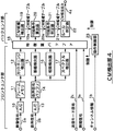
図2には、上記CM検出部4の第1の具体例の詳細な構成を示す。なお、この図2中の各信号のうち、図1と共通の信号については、図1と同じ指示符号を付している。また、当該CM検出部4は、大別して、フロントエンド部とバックエンド部とから構成されている。また、図中の動作制御部23は、チューナ1から供給された上記チャンネル情報1bに基づいて、上記チューナ1において明らかにCMが放送されない放送チャンネルの指定がなされているか否か判断し、その判断結果に応じて、当該図2の各部におけるCM検出動作を行わないように制御するものである。
【0056】
先ず、図2のフロントエンド部から説明する。
【0057】
この図2において、図1の復調器2より供給された映像信号2aは、A/D変換器10にてディジタル化され、フレームメモリ11に蓄えられる。なお、フレームメモリ11は、少なくとも2フレーム分の映像信号を蓄積可能なメモリである。当該フレームメモリ11からフレーム毎に読み出された映像信号は、カットチェンジ検出器12に送られる。
【0058】
カットチェンジ検出器12は、フレームメモリ11より供給されたフレーム毎の映像信号に基づいて、映像が急激に変化するフレーム(以下、映像変化フレームと呼ぶ)と、輝度が一様となるフレーム(以下、一様輝度フレームと呼ぶ)を検出する。
【0059】
すなわち、カットチェンジ検出器12は、フレームメモリ11に蓄えられた時間的に隣接する2つのフレーム映像間で、各画素毎に輝度の差分の自乗和を求め、当該自乗和が所定の閾値を越えた場合に、上記隣接する2つのフレームのうちの時間的に後のフレームを、上記映像が急激に変化する映像変化フレームとして検出する。また、カットチェンジ検出器12は、フレームメモリ11に蓄えられた各フレーム映像の輝度の分散を求め、その輝度の分散値が所定の閾値以下である場合に、そのフレームを一様輝度フレームであるとして検出する。なお、フレームの間隔(NTSC方式では約30ms)が、後述する音声信号処理において説明するフレーム周期と一致しない場合には、当該フレーム間隔を再離散化することによって、フレーム周期と一致させておくようにする。
【0060】
以下、当該カットチェンジ検出器12における映像変化フレームと一様輝度フレームの検出について、より具体的に説明する。
【0061】
ここで、離散化された映像信号の横サイズをX、縦サイズをY、縦横の画素番号をx,yとし、第nフレームの映像をIn(x,y)、当該第nフレームに対して時間的に1フレーム前の第n−1フレームの映像をIn-1(x,y)として表わすと、第nフレームと第n−1フレームの間の各画素毎の輝度差分の自乗和D[n]は、式(1)により得られ、また、第nフレームの輝度分散値V[n]は、式(2)により得られる。
【0062】
【数1】

また、このときのカットチェンジ検出器12の検出出力C[n]は、式(3)により表わされる。
【0064】
【数2】
ただし、式中のDthsdは上記映像変化フレームを検出する際の前記自乗和に対する所定の閾値であり、Vthsdは上記一様輝度フレームを検出する際の前記輝度の分散値に対する所定の閾値である。
【0066】
当該カットチェンジ検出器12の検出出力C[n]は、映像信号についての特徴量として特徴量バッファ18へ送られる。
【0067】
なお、上記の2つのフレーム映像間で輝度差分を求める際には、2フレーム分の映像信号を蓄積可能なメモリが必要となり、また、2フレーム分の映像信号に対する演算量も必要となる。そこで、例えばフレーム映像全面を同時に処理する代わりに、フレーム映像を適切な小ブロック毎に分け、その小ブロック毎に輝度差分を求めるようにしたり、或いは、フレーム映像間の各画素毎に輝度差分を求めるのではなく、各フレーム映像毎に輝度ヒストグラムを求めて、その輝度ヒストグラムのフレーム間差分を求めるようにしたり、又は、各フレーム映像毎に平均輝度を求めて、その平均輝度のフレーム間差分を求めるようにするで、メモリ容量や演算量を減らすことも可能である。逆に、メモリや演算量に余裕がある場合には、例えば、カラー映像におけるR(赤),G(緑),B(青)成分のようなカラー成分毎に、上記輝度差分やカラーヒストグラム差分を求めることで、より検出精度を高めることも可能である。
【0068】
次に、図1の復調器2より供給された音声信号2bは、A/D変換器13にてディジタル化され、音声信号バッファ14に蓄えられる。なお、音声信号バッファ14は、少なくとも所定時間T1(例えば30ms、以下、これを1フレーム長とする)分の左(L)右(R)2チャンネルのステレオ音声信号を蓄積可能なメモリである。当該音声信号バッファ14から読み出された音声信号は、振幅検出器15、相関検出器16、スペクトル検出器17に送られる。
【0069】
振幅検出器15は、音声信号バッファ14に蓄えられた音声信号を用いて、所定の時間T2(例えば15ms、以下、これを1フレーム周期とする)毎の短時間平均自乗振幅を検出する。すなわち、振幅検出器15は、音声信号バッファ14に左右2チャンネルのステレオ音声信号が蓄積されている場合、当該音声信号バッファ14より読み出された左右2チャンネルのステレオ音声信号SL[m],SR[m]から、所定の時間T2(15ms、1フレーム周期)毎に、短時間平均自乗振幅を検出する。なお、上記m(m=0,・・・,M−1)は、離散化された時間を表わすバッファ内のサンプル番号であり、最大番号Mが1フレーム長T1に対応する。
【0070】
より具体的に説明すると、振幅検出器15は、第nフレームにおける左右2チャンネルの音声信号の平均自乗振幅A[n]を式(4)により計算する。すなわち、平均自乗振幅は15ms(1/2フレーム)毎に計算され、その15ms毎の平均自乗振幅の30ms(1フレーム)の期間における平均値がさらに演算され、最終的な、1フレームの平均自乗振幅とされる。
【0071】
【数3】
当該振幅検出器15の検出出力である平均自乗振幅A[n]は、音声信号についての特徴量の一つとして特徴量バッファ18へ送られる。
【0073】
相関検出器16は、音声信号バッファ14に蓄えられた音声信号を用いて、1フレーム毎の音声信号について規格化前の相関係数を検出すると共に、後段にて行われる規格化のための短時間エネルギーも同時に検出する。すなわち、相関検出器16は、音声信号バッファ14に左右2チャンネルのステレオ音声信号が蓄積されている場合、当該音声信号バッファ14より読み出された左右2チャンネルのステレオ音声信号SL[m],SR[m]から、1フレーム毎の左右2チャンネルの音声信号について規格化前の相関係数を検出すると共に、後段にて行われる規格化のための短時間エネルギーも同時に検出する。
【0074】
より具体的に説明すると、相関検出器16は、第nフレームにおける左右2チャンネルの音声信号の相関係数ALR[n]を式(5)により計算し、左チャンネルの音声信号エネルギーALL[n]を式(6)により計算し、右チャンネルの音声信号エネルギーARR[n]を式(7)により計算する。
【0075】
【数4】
当該相関検出器16の検出出力である相関係数ALR[n]と音声信号エネルギーALL[n]、ARR[n]は、それぞれが音声信号についての特徴量の一つとして特徴量バッファ18へ送られる。
【0077】
スペクトル検出器17は、音声信号バッファ14に蓄えられた音声信号を用いて、短時間スペクトルを計算する。すなわち、スペクトル検出器17は、音声信号バッファ14に左右2チャンネルのステレオ音声信号が蓄積されている場合、当該音声信号バッファ14より読み出された左右2チャンネルのステレオ音声信号SL[m],SR[m]から、短時間スペクトルを計算する。
【0078】
より具体的に説明すると、スペクトル検出器17は、第nフレームにおける左右2チャンネルの音声信号の離散スペクトルF[k;n]を求める。なお、k=0,・・・,K−1を離散化された周波数を表わす番号とすると、離散スペクトルF[k;n]は式(8)により表わされる。
【0079】
【数5】
この式(8)の演算は、例えば、高速フーリエ変換(FFT)又は線形予測分析(LPC)などを用いて実現される。
【0081】
当該スペクトル検出器17の計算出力である短時間離散スペクトルF[k;n]は、音声信号についての特徴量の一つとして特徴量バッファ18へ送られる。
【0082】
次に、図1の復調器2より供給された放送モード信号2cは、上述した音声信号処理のフレームに合わせて離散化された数値となされる。
【0083】
より具体的に説明すると、第nフレームにおける放送モード信号2cは、例えば式(9)のような数値B[n]となされる。
【0084】
【数6】
この放送モード信号2cを離散化した数値B[n]は、TV放送信号の特徴量の一つとして特徴量バッファ18へ送られる。
【0086】
同様に、図1の時計部3より供給された時間信号3aも、音声信号処理のフレームに合わせて離散化された数値T[n]となされ、特徴量の一つとして特徴量バッファ18へ送られる。
【0087】
特徴量バッファ18は、上記カットチェンジ検出器12からの検出出力C[n]と、振幅検出器15からの平均自乗振幅A[n]と、相関検出器16からの相関係数ALR[n]、音声信号エネルギーALL[n],ARR[n]と、スペクトル検出器17からの短時間離散スペクトルF[k;n]と、放送モード信号2cの離散化数値B[n]と、時間信号3aの離散化数値T[n]とからなる、式(10)に示される特徴量G[n]を、所定の時間T3に渡って蓄積する。なお、時間T3はCM部分を最低でも1つ以上に渡って記憶できる時間であり、例えば80秒などとする。
G[n]={C[n],A[n],ALR[n],ALL[n],ARR[n],F[k;n],B[n],T[n]} (10)
【0088】
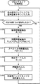
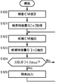
以上のA/D変換器10から特徴量バッファ18までが、図2に示したCM検出部4のフロントエンド部の構成であり、以下、図3、図4のフローチャートを用いて当該フロントエンド部における処理の流れを説明する。なお、図3のステップS30乃至S32までは映像信号2aについての処理の流れを表しており、図4のステップS33乃至S40までは音声信号2b及び放送モード信号2c、時間信号3aについての処理の流れを表している。
【0089】
先ず、映像信号2aについての処理の流れを表す図3において、フロントエンド部は、ステップS30の処理として、A/D変換器10によりディジタル化された、少なくとも1フレーム分の映像信号2aをフレームメモリ11に蓄える。このフレームメモリ11は、1フレーム分の映像信号2aを1サンプルとして扱うようになされており、1フレーム分の映像信号2aが入力されると、当該フレームメモリ11内に既に蓄積されている映像信号2aが1フレーム分シフトし、最も時間的に過去に入力された1フレームの映像信号2aが押し出されて出力されるようになっている。
【0090】
次に、フロントエンド部は、ステップS31の処理として、フレームメモリ11から映像信号2aを読み出してカットチェンジ検出器12に送り、前述のようにして検出出力C[n]を求める。
【0091】
その後、フロントエンド部は、ステップS32の処理として、当該検出出力C[n]を特徴量バッファ18に蓄える。
【0092】
一方、音声信号2bについての処理の流れを表す図4において、フロントエンド部は、ステップS33及びステップS34の処理として、A/D変換器13によりディジタル化された、音声信号2bを音声信号バッファ14に入力すると共に、当該音声信号バッファ14に少なくとも1フレーム周期T2分の音声信号2bを蓄積する。この音声バッファ14は、1フレーム周期T2分の音声信号2bを1サンプルとして扱うようになされており、1フレーム周期T2分の音声信号2bが入力されると、当該音声バッファ14内に既に蓄積されている音声信号2bが1フレーム周期T2分だけシフトし、最も時間的に過去に入力された1フレーム周期T2分の音声信号2bが押し出されて出力されるようになっている。
【0093】
上記音声信号バッファ14に少なくとも1フレーム周期T2分の音声信号2bが蓄積されると、フロントエンド部は、ステップS35の処理として、当該音声信号バッファ14に蓄積された音声信号2bを読み出して振幅検出器15に送り、前述のようにして、平均自乗振幅A[n]を求める。
【0094】
同時に、フロントエンド部は、ステップS36の処理として、音声信号バッファ14に蓄積された音声信号2bを相関検出器16に送り、前述のようにして、相関係数ALR[n]と音声信号エネルギーALL[n]、ARR[n]を求める。
【0095】
また同時に、フロントエンド部は、ステップS37の処理として、音声信号バッファ14に蓄積された音声信号2bをスペクトル検出器17に送り、前述のようにして、短時間離散スペクトルF[k;n]を求める。
【0096】
さらに、フロントエンド部は、ステップS38の処理として、図1の復調器2より供給された放送モード信号2cから、前述のように離散化した数値B[n]を求めると共に、図1の時計部3より供給された時間信号3aから、前述のように離散化された数値T[n]を求める。
【0097】
フロントエンド部は、以上にようにして求められた、上記カットチェンジ検出器12からの検出出力C[n]と、振幅検出器15からの平均自乗振幅A[n]と、相関検出器16からの相関係数ALR[n]、音声信号エネルギーALL[n],ARR[n]と、スペクトル検出器17からの短時間離散スペクトルF[k;n]と、放送モード信号2cの離散化数値B[n]と、時間信号3aの離散化数値T[n]とからなる特徴量G[n]を、特徴量バッファ18に蓄積する。
【0098】
図2に戻り、バックエンド部の説明を行う。なお、以下の説明において、番号nは、特徴量バッファ18内にフレーム毎に蓄積される特徴量の、各フレーム番号を表わすものとする。また、最新のフレームの特徴量をG[0]とし、過去のフレームの特徴量となるにしたがってnの値が増加し、新たなフレームの特徴量が入力された場合には、全てのデータが1ずつシフト(フレーム番号が1ずつシフト)するものとする。
【0099】
図2において、特徴量バッファ18に蓄積された特徴量は、フレーム毎にCM候補検出器19に送られる。
【0100】
当該CM候補検出器19は、ほぼ全てのCMが満たす、前述した「必須条件」に基づき、フレーム毎にCM区間の候補を算出する。ここで、必須条件とは、前述したように、CMの音声信号が「小音量」であること、すなわち音声信号の音量が所定の閾値以下となっているフレーム(以下、音量条件と呼ぶ)であり、且つ、CMの「映像切り替わり」があること、すなわち映像信号が急激に変換するフレーム又は一様な輝度となるフレーム(以下、映像条件と呼ぶ)であり、さらに、「規定時間長(少数種類の時間長)」であること、すなわち上記音量条件と映像条件を満たす2つのフレームの間隔が所定のCM長と合致する区間(以下、時間条件と呼ぶ)となるような条件であり、具体的には、前述の特徴量を用いて、以下のような式(11)で且つ式(12)で且つ式(13)の条件として書き下すことができる。
【0101】
A[0]<Athsd (11)
C[0]=1 (12)
A[n1]<Athsd,C[n1]=1又はA[n2]<Athsd,C[n2]=1又は
A[n3]<Athsd,C[n3]=1 (13)
ただし、Athsdは所定の自乗振幅の閾値であり、n1,n2,n3はそれぞれCM長として規定されている時間長(本実施の形態では、一例として15秒、30秒、60秒の3種類の時間長がある場合を説明に用いている)を、フレーム周期単位に換算した数である。なお、CMの実際の放送時間には誤差があるため、実用上は、n1,n2,n3にはそれぞれ多少の幅を持たせる。
【0102】
ここで、図5を用いて、上記CM候補検出器19の動作の流れを説明する。
【0103】
図5において、特徴量バッファ18では、ステップS50のバッファシフト処理とステップS51の特徴量入力処理として、図3のステップS32で説明したフレームメモリと図4のステップS40で説明した音声信号バッファと同様に、1フレーム単位の入力、シフト及び出力の動作を行うようになされている。すなわち、特徴量バッファ18は、1フレーム分の特徴量を1サンプルとして扱うようになされており、1フレーム分の特徴量が入力されると、当該特徴量バッファ18内に既に蓄積されている特徴量が1フレーム分だけシフトし、最も時間的に過去に入力された1フレーム分の特徴量が押し出されて出力されるようになっている。
【0104】
上記ステップS50及びステップS51の処理により、特徴量バッファ18から1フレーム(1サンプル)分の特徴量が入力されると、CM候補検出器19は、ステップS52及びステップS53の処理として、1フレーム(サンプル)に特徴量が上記必須条件の音量条件、映像条件、時間条件を満たすか否かの評価を行う。すなわち。CM候補検出器19は、ステップS52において、先ず最初のフレームの平均自乗振幅A[0]と所定の自乗振幅の閾値Athsdを比較し、次に、ステップS53の処理として、前記検出出力C[0]が1となるか否か調べることにより、当該フレームが上記必須条件である音量条件、映像条件、時間条件を満たすか否かの判定を行う。CM候補検出器19では、これらステップS52,S53の判定処理の結果、上記平均自乗振幅A[0]が所定の自乗振幅の閾値Athsdを超えず、且つ、上記必須条件を満たしていると判定した場合、当該フレームをCM候補としてステップS57以降(ステップS54乃至S56については後述する)の処理に進み、逆に、上記平均自乗振幅A[0]が所定の自乗振幅の閾値Athsdを超えたか、或いは上記必須条件を満たしていないと判定した場合、当該フレームがCM候補にはならないとしてステップS50の処理に戻る。
【0105】
上記ステップS52,S53の各判定処理の結果、上記平均自乗振幅A[0]が所定の自乗振幅の閾値Athsdを超えず、且つ、上記必須条件を満たしていると判定された場合、CM候補検出器19は、ステップS57の処理としてCM開始フレームnsを検索し、次に、ステップS58の処理としてCM終了フレームneの検索を行い、更に、ステップS59の処理としてCM開始時刻Tsを計算し、ステップS60としてCM長さWを計算する。
【0106】
CM候補検出器19は、以上のステップS57乃至S60の検索及び計算を行った後、ステップS61において後述するCM候補テーブルを参照し、もし、CM開始時刻Ts及びCM長さTwの一致する候補がすでに当該CM候補テーブル中に存在するならば、そのまま再びステップS54乃至S56の処理に戻り、逆に存在しない場合には、新たなCM候補としてCM候補テーブルに追加した後、再びステップS54乃至S56の処理に戻る。
【0107】
ステップS54乃至S56では、全ての時間長に対して上述同様の処理を行った後、ステップS50に戻り、次の入力に対して同じ処理を繰り返すことを表している。
【0108】
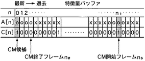
なお、上記CM開始フレームnsとは、n1,n2,n3で表される各フレームのうち時間条件に合致したフレームから、最新フレームの方向へ向かって、平均自乗振幅A[n]が自乗振幅の閾値Athsdを越える最初のフレーム番号である。また、CM終了フレームneとは、0番目のフレームより過去の方向に向かって、平均自乗振幅A[n]が自乗振幅の閾値Athsdを越えない最後のフレーム番号である。さらにCM開始時刻Tsは、CM開始フレーム番号nsを用いてTs=T[ns]として求められる。同様にCM長さTwは、Tw=T[ne]−T[ns]として求められる。
【0109】
ここで、図6に、上記必須条件の算出例を示す。この図6に示すA[n]の項において、「o」は自乗振幅の閾値Athsd未満の平均自乗振幅を持つフレームを示し、「x」は自乗振幅の閾値Athsd以上の平均自乗振幅を持つフレームを示している。この例では、A[0],C[0]及びA[n1],C[n1]が条件を満たし、n1より左方で最初にA[n]=xとなるフレームがns、0より右方に連続する最後のA[n]=oとなるフレームがneとなる。
【0110】
以上の処理により、CM候補検出器19では、1フレーム(1サンプル)の特徴量が入力される毎にCM候補の検出を行い、CM候補が検出された場合にはCM候補テーブルにエントリーする。
【0111】
図7には、CM候補テーブルの構成例を示す。この図7において、CM候補テーブルの項目は、開始時刻Ts、長さTw、及び後述する付加条件算出器20で算出する特徴量Q1乃至Q11、及び後述する付加条件判定器21で算出するスコアRとスコア判定結果Zからなる。CM候補検出器19によるCM候補テーブル19aの段階では、開始時刻Ts、長さTwのみが記述される。このように、CM候補テーブルは、CM候補検出器19で得られるCM開始時刻Ts、長さTwと、付加条件算出器20で算出される特徴量Q1乃至Q11と、付加条件判定器21で算出されるスコアR及びスコア判定結果Zとを記述し、それら特徴量を管理するための表である。また、CM候補テーブルは、そのエントリーがCMであるかないかの判定を受けるまで保持され、CMであると判断された場合には、後述するルール判定器22からCM検出出力4aとして出力され、CMでないと判断された場合には破棄される。
【0112】
上記CM候補検出器19により開始時刻Ts、長さTwのみが記述されたCM候補テーブル19aは、付加条件算出器20に送られる。
【0113】
付加条件算出器20では、CM候補テーブル19aにエントリーされた候補区間より、特徴量バッファ18を参照しながら、以下に示すような特徴量Q1乃至Q11を抽出し、それをCM候補テーブル19aに追加記述し、CM候補テーブル20aとして付加条件判定器21に出力する。
【0114】
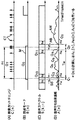
図8には、当該付加条件算出器20における特徴量Q1乃至Q11の算出例を示す。
【0115】
この図8において、横軸はフレーム番号(離散時間に相当)を表し、図8(A)はカットチェンジ検出出力C[n]、図8(B)は放送モード信号2cの離散化数値B[n]、図8(C)は音声信号の短時間離散スペクトルS[k,n]、図8(D)は音声信号の平均自乗振幅A[n]を表わし、n1の間隔(図中点線で挟まれた区間)がCM候補である。なお、図8(A)において、図中CTで示す位置はカットチェンジ検出出力C[n]が1となっている位置(すなわちカットチェンジが検出された位置)を示している。また、図8(B)において、図中Mで示す区間はその区間が何らかの放送モードとなっていることを示している。図8の(C)において、図中S1,S2,S3,S4は何らかのスペクトル成分が存在することを示し、図8(D)において、図中AMは自乗振幅の変化を表している。また、図中Q1からQ11は、上記付加条件算出器20にて特徴量Q1乃至Q11が計算される場所を示している。
【0116】
以下、付加条件算出器20で算出される各特徴量Q1乃至Q11について個々に説明する。
【0117】
特徴量Q1は前ブレーク長である。当該前ブレーク長とは、CM候補区間直前の小音量区間(前ブレーク区間と称する)、すなわち連続してA[n]が所定の閾値Athsd以下である時間長であり、図8中の一点鎖線で挟まれた区間長BBが前ブレーク長Q1である。
【0118】
特徴量Q2は後ブレーク長である。当該後ブレーク長とは、CM候補区間直後の小音量区間(後ブレーク区間と称する)、すなわち連続してA[n]が所定の閾値Athsd以下である時間長であり、図8中の一点鎖線で挟まれた区間長ABが後ブレーク長Q2である。
【0119】
特徴量Q3は前ブレーク最小振幅である。当該前ブレーク最小振幅Q3は、前記の前ブレーク区間におけるA[n]の最小値である。
【0120】
特徴量Q4は後ブレーク最小振幅である。当該後ブレーク最小振幅Q4は、前記の後ブレーク区間におけるA[n]の最小値である。
【0121】
特徴量Q5は左右相関値である。当該左右相関値Q5は、CM候補区間の音声の左右2チャンネルの音声信号SL[m]、SR[m]の相関値である。これは、式(5)乃至式(7)のALR[n],ALL[n],ARR[n]を利用して、式(14)に従って算出することができる。
【0122】
【数7】
この式(14)の演算では、フレームのオーバーラップにより原波形が部分的に複数回加算されることになるが、そのことはこのシステムに実質的な影響は及ぼさない。また、原波形をそのまま保持できるだけのメモリ容量及び処理速度がある場合には、この演算は原波形の相互相関と置き換えることもできる。
【0124】
特徴量Q6は平均振幅値である。当該平均振幅値Q6は、CM候補区間の音声信号の振幅のRMS値(平均自乗振幅)である。これは、式(15)により計算することができる。
【0125】
【数8】
この式(15)の演算では、上記左右相関演算の場合と同様に、フレームのオーバーラップ次第では原波形が部分的に複数回加算されることになるが、そのことは実質的な影響を及ぼさない。また、原波形をそのまま保持できるだけのメモリ容量及び処理速度がある場合には、この演算は原波形のRMS演算と置き換えることもできる。
【0127】
特徴量Q7はカット数である。当該カット数Q7は、CM候補区間中に存在するカットチェンジの回数(上記CTの数)を数える演算となる。すなわちこれは、[ns,ne)の区間でC[n]=1となる回数を数える演算となる。
【0128】
特徴量Q8は放送モードである。ここでの放送モードは、CM候補区間中で最も支配的な放送モードのことである。これは、[ns,ne)の区間のB[n]値の中で、最も頻発する放送モードQ8を選ぶ演算である。
【0129】
特徴量Q9は隣接候補数である。当該隣接候補数Q9は、あるCM候補に対して、その前後にある有音区間もCM候補であるかどうかを表わし、両側ともCM候補であれば「2」、片側のみCM候補であれば「1」、どちらもCM候補でなければ「0」の値をとる。この演算は、CM候補テーブルを検索することで行われ、開始時刻Tsと長さTwと後ブレーク長Q2の和(Ts+Tw+Q2)が、他のCM候補の開始時刻(T's)と一致するかどうかで後側候補の判定が行われる。同様に、開始時刻Tsと前ブレーク長Q1の差(Ts−Q1)が、他のCM候補の開始時刻T'sと長さT'wの和(T's+T'w)と一致するかどうかで、前側候補の判定が行われる。
【0130】
特徴量Q10,Q11はスペクトル差分エネルギーである。当該スペクトル差分エネルギーQ10,Q11は、CMと番組本編やCMと他のCMとの境界での音質変化を定量化するために用いられる。これは、上記境界の両側における平均スペクトルの差の自乗和として定義され、式(16)乃至(21)に従って計算される。
【0131】
【数9】
但し、式中のNはスペクトルの平均をとるフレーム数、n'eはCM候補区間の直前の有音区間の終了フレーム番号(図8参照)、n'sはCM候補区間の直後の有音区間の開始フレーム番号、S1[k]はCM候補区間の直前の有音区間の終了直前の平均スペクトラム、S2[k]はCM候補区間開始直後の平均ズクトラム、S3[k]はCM候補区間終了直前の平均スペクトラム、S4[k]はCM候補区間の直後の有音区間の開始直後の平均スペクトラム、Snormは適切な規格化定数である。
【0133】
上記付加条件算出器20は、以上により算出したQ1からQ11までの特徴量を、CM候補テーブル19aに追加記述し、CM候補テーブル20aとして出力する。当該CM候補テーブル20aは、付加条件判定器21に送られる。
【0134】
付加条件判定器21は、CM候補テーブル20aを入力とし、CM候補の特徴量を、閾値関数などにより非線型にパラメータ変換した後、荷重加算することでCM候補に対するスコアRを算出し、Rが所定の閾値以上である場合には有力CM候補と判定する。付加条件判定器21は、これらスコアRとスコア判定結果ZをCM候補テーブル20aに追加記述し、CM候補テーブル21aとして出力する。
【0135】
図9には、付加条件判定器21の概略構成を示す。
【0136】
この図9において、CM候補テーブル21aの各特徴量Q1乃至QLは、それぞれ対応する関数演算器501乃至50Lに送られ、それぞれ対応するパラメータ変換関数H1()乃至HL()による変換演算が施された後、さらにそれぞれ対応する重み付け器511乃至51Lにより荷重W1乃至WLとの積がとられる。各重み付け器511乃至51Lにより重み付けがなされた後の特徴量は、総和加算器52での総和加算によりスコアRが算出される。この総和加算器52から出力されたスコアRは、スコア判定器53にて所定の閾値と比較され、スコアRが所定の閾値以上である場合には有力CM候補である旨を示す判定結果が出力される。なお、スコア判定器53によるスコア判定により所定の閾値未満であると判定されたCM候補は、テーブルから消去される。
【0137】
より具体的に説明すると、当該付加条件判定器21におけるスコア算出演算は、式(22)に従って行われる。
【0138】
【数10】
ただし、Hl()は各特徴量に対して予め定めるパラメータ変換関数、Wlは予め決定しておく荷重、Lは特徴量数(=11)である。なお、lは1乃至11のうちの任意の数である。
【0140】
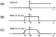
ここで、各関数演算器501乃至50Lにおけるパラメータ変換関数Hl()は、最も簡単には矩形関数でよい。すなわち例えば、図10(B)に示すような矩形関数Rect(x;t1,t2)を用い、予め各特徴量について決定しておく標準値の下上限値をt1l,t2lとし、式(23)により例えばQ1が標準値の範囲内ならば1、範囲外ならば0となるようにする。
【0141】
Hl(Ql)=Rect(Ql;t1,t2) (23)
なお、前記境界付近で滑らかに0から1、1から0へ推移させるようにする場合には、例えば式(24)のような、シグモイド関数Sigm(x;t1,t2)を用いることもできる。
【0142】
【数11】
図10(C)にシグモイド関数の概形を示す。ただし、s1l,s2lは推移の程度を表わす定数であり、予め特徴量の分布などに基づき決定しておく。
【0144】
また、上記各重み付け器511乃至51Lによる加算荷重Wlは、予め特徴量の統計的性質に基づき人為的に決定しておくこともできるが、既知の学習サンプルに対して、ニューラルネットワーク(例えば中川著「パターン情報処理」丸善(1999)などに詳説)の要領で学習することで、自動的に荷重を決定することも可能である。なお、lは1乃至11のうちの任意の数である。
【0145】
さらに、上記判定器53におけるスコア判定は、式(25)のように、スコアRの閾値処理により行う。
【0146】
Z=Unit(R−tr) (25)
ただし、Unit(x)は、図10(A)に示すように、x>0で1、x<0で0となる単位ステップ関数であり、trは予め定めるか或いは学習により自動的に決まる判定閾値である。
【0147】
次に、ルール判定器22は、上記付加条件判定器21でのスコア判定により得られたCM候補テーブル21aを入力とし、後述するような所定のルール判定により最終的なCM検出出力4aとしてCM開始時刻と長さを出力する。すなわち、当該ルール判定器22では、同一時刻に複数のCM候補があった場合(以下、競合関係という)に、どちらがよりCMとして確からしいかをルール処理により判定する。
【0148】
以下、ルール判定器22の動作を図11のフローチャートを用いて説明する。
【0149】
先ず、ルール判定器22は、ステップS70として、CM候補テーブルより、判定すべきCM候補を選択する。この選択は、CM候補テーブル中で最古の候補であり、予め設定された時間T4が経過したものから順に行われる。T4は、数個のCMが十分含まれる程度の時間長であり、例えば150秒間とする。
【0150】
続いて、ルール判定器22は、ステップS71として、選択したCM候補の区間中(TsからTs+Twまでの間)に、他のCM候補が存在するかどうか、CM候補テーブル中を検索する。このステップS71において、他のCM候補が存在しないと判定した場合(No)、このCM候補はCM検出出力として出力され、CM候補テーブルより消去される。
【0151】
一方、ステップS71において、他のCM候補が存在すると判定された場合(Yes)、それらは競合関係にあるとして、ステップS72にて先ず最小長さ優先ルールが適用される。ここで、最小長さ優先ルールは、ある時区間が、複数の長さの異なるCM候補の組み合わせにより構成され得る場合、より短いCM候補で構成されている方を優先するというルールである。すなわち、例えば30秒という時区間に対して、1つの30秒CMという可能性と、2つの15秒CMの組み合わせという可能性の、両方が同時に候補として存在する場合には、15秒CMを選択し、30秒CMを棄却するというルールである。
【0152】
図12を用いて、この最小長さ優先ルールの一例を説明する。
【0153】
なおこの例には、図12(A)のように、実際には4つのCM1乃至CM4が連続して放送されている区間に対し、図12(B)中A乃至Hで示すような8つの候補がCM候補テーブルに存在する場合が示されている。
【0154】
先ず、図12(C)に示すように、AのCM候補が判定中であるとすると、この候補Aと競合する候補はEとHである。しかしながら、Eの区間はAとBで記述でき、また、Hの区間はAとBとCとD等で記述できることから、それぞれ棄却され、Aが採用される。続いて、図12(D)に示すように、Bが判定中となったときには、Fが競合相手となる(このとき、E、HはAの判定により棄却済みとなっている)が、Fの区間はBとCで記述できることから棄却され、Bが採用される。同様に、図12(E)に示すように、Cが判定中の場合には、Gが競合相手となるが、Gの区間はCとDで記述されることから棄却され、Cが採用される。最後に、図12(F)に示すように、Dが判定されるときには、すでに競合相手は存在しないので、そもそもこのルールを適用する必要はなく、当該Dがそのまま採用される。
【0155】
以上により、この時区間からは、CM候補としてA,B,C,Dが選択されることとなる。このルールが適用できない競合関係については、そのままCM候補テーブルに残してこの処理を終了する。
【0156】
図11に戻り、ステップS72のルール判定の後、ルール判定器22の処理は、ステップS73に進む。ステップS73に進むと、ルール判定器22は、最小長さ優先ルールを適用した結果、判定中のCMが棄却されたか否か判断する。このステップS73において、判定中のCMが棄却されと判断した場合(Yes)、ルール判定器22は、その候補をCM候補テーブルから消去し、ステップS70に戻る。一方、ステップS73において、判定中のCMが棄却されていないと判断した場合(No)、ルール判定器22は、ステップS74において、再び判定中のCM候補の区間中に他のCM候補が存在するかどうか、テーブル中を検索する。
【0157】
このステップS74において他のCM候補が存在しないと判定した場合(No)、ルール判定器22は、ステップS80において判定中のCM候補をCM検出出力から出力し、CM候補テーブルから消去する。一方、ステップS74にて他のCM候補が存在すると判断した場合(Yes)、ルール判定器22の処理は、ステップS75に進む。
【0158】
ステップS75に進むと、ルール判定器22は、隣接優先ルールを適用する。ここで、隣接優先ルールとは、複数のCM候補が競合関係にある場合、それぞれ直前又は直後に隣接するCM候補を検索し、それが存在する方を優先するというルールである。
【0159】
図13を用いて、当該隣接優先ルールについて説明する。
【0160】
なおこの例には、図13(A)のように、実際には4つのCM11乃至CM14が連続して放送されている区間に対し、図13(B)中I乃至Nで示すような6つの候補が存在する場合が示されている。また、この例の場合、候補M及びNは、偶然CM中にカットチェンジや小音量区間が存在したために候補となっているが、このような候補は、実際には誤った区間であるとはいえ、内容的にはCMを含んでいるため、CMらしさを判定する付加条件のスコア判定によっても、棄却されない場合があるものである。
【0161】
このような例において、先ず、図13(C)に示すように、最古のIが判定される候補となる。当該Iと競合するものとしてMがあるが、Iには隣接する候補Jが存在するのに対し、Mには隣接する候補がないため、Iを採用し、Mを棄却する。次に、図13(D)に示すように、Jが判定される候補となった場合、Jと競合する候補としてNがあるが、Jには隣接する候補I、Kが存在するのに対し、Nには存在しないため、Jが採用されNが棄却される。次に、図13(E),(F)に示すように、残りの候補K、Lには、既に競合する候補がなくなるため、このルールは適用されず、これらK、Lがそのまま採用される。
【0162】
以上により、この図13に例示した区間からは、I,J,K,LがCM候補として選択されることとなる。
【0163】
なお、競合関係の候補のいずれにも隣接候補が無い場合、及び複数の候補にそれぞれ隣接候補がある場合には、それらはどちらも棄却されず、CM候補テーブルに残される。
【0164】
図11に戻り、ステップS75の処理後、ルール判定器22の処理は、ステップS76に進む。ステップS76に進むと、ルール判定器22は、隣接優先ルールを適用の結果、判定中のCMが棄却されたか否か判断する。このステップS76において、判定中のCMが棄却されたと判断した場合(Yes)、ルール判定器22は、その候補をCM候補テーブルから消去し、ステップS70の処理に戻る。一方、ステップS76において棄却されていないと判定された場合(No)、ルール判定器22は、次のステップS77において、再び判定中のCM候補の区間中に、他のCM候補が存在するかどうか、CM候補テーブル中を検索する。
【0165】
このステップS77において、他のCM候補が存在しなと判定された場合(No)、ルール判定器22は、ステップS80において、判定中のCM候補をCM検出出力から出力し、CM候補テーブルから消去する。一方、ステップS77において、他のCM候補が存在すると判定した場合(Yes)、ルール判定器22は、ステップS78において、スコア優先ルールを適用する。ここで、スコア優先ルールとは、上記の各ルールによっても競合関係が解消されない場合、付加条件判定器21により得られた判定スコアRの高い候補を優先するというルールである。このスコア優先ルールは、対象となる競合関係が解消するまで繰り返し適用する。
【0166】
図14を用いて、当該スコア優先ルールについて説明する。
【0167】
なおこの例には、図14(A)のように、実際には4つのCM21乃至CM24が連続して放送されている区間に対し、図14(B)中P乃至Wで示すような7つの候補が存在する場合が示されている。
【0168】
この例において、先ず、図14(C)に示すように、最古のPが判定される候補となるが、この候補PはUと競合関係がある。但し、このときの競合関係は、前記最小長さ優先ルールによっても、また、隣接優先ルールによっても競合が解消されない。
【0169】
したがって、この場合には、これら競合関係にある候補と関連する全ての競合関係を、CM候補テーブル中から検索する。すなわち、この場合は、(P−U)、(U−Q)、(Q−V)、(V−R)、(R−W)、(W−S)という、7候補に対する6つの競合関係が全て関連しているので、スコア優先ルールでは、これら関連する候補の中で最もスコアの高い候補を採用する。この例の場合、判定スコアR(2.0)が最も高いスコアであるため、図14(D)に示すように、このスコアが採用され、その結果、Rと競合関係にある候補V、Wは棄却される。
【0170】
しかしながら、図14(E)に示すように、これによっても(P−U)の競合関係は解消されていない。したがって、再びこれらと関連する全ての競合関係を、CM候補テーブル中から検索する。今回は、Vが棄却されたことにより、(P−U)、(U−Q)という、3つの候補が関係する2つの競合関係のみとなる。
【0171】
さらに、これらの候補の中で最もスコアの高い候補Q(1.9)を採用し、図14(F)に示すように、Qと競合関係にある候補Uを棄却する。
【0172】
以上によって、Pに関係する競合関係はなくなり、Pが採用される。また、U、V、Wは全て棄却され、Q、R、Sが採用されることとなる。
【0173】
なお、仮に、関連する全ての競合関係を検索せず、対象となる競合関係(この例の場合、P,U)のみでスコア優先ルールを適用すると、先ずUが採用され、Pは棄却される。後にUとQとの競合関係により、一時採用されたUもまた棄却されてしまう。このように、ルール判定器22では、偶然の処理順序により候補Pが棄却されるようなことのないよう、関連競合関係の検索を行っている。
【0174】
以上のスコア優先ルールにより、選択された候補に関する競合関係は必ず解消されることになる。
【0175】
図11に戻り、ステップS78の処理後、ルール判定器22の処理は、ステップS79に進む。ステップS79に進むと、ルール判定器22は、スコア優先ルールを適用の結果、判定中の候補が棄却されたか否か判断する。このステップS79において、判定中の候補が棄却されたと判断した場合(Yes)、ルール判定器22は、その候補をCM候補テーブルより消去し、ステップS70に戻る。一方、ステップS79において、棄却されなかった場合、ルール判定器22は、ステップS80のCM検出出力として、開始時刻とその長さを出力し、CM候補テーブルから消去した後、ステップS70に戻る。
【0176】
以上説明したように、本実施の形態の第1の具体例のCM検出部4においては、ほぼ全てのCMが満足する必須条件に基づき、決定論的に番組中からCMの候補を抽出し、CMらしさの指標である付加条件に基づく特徴量の統計論的な評価により候補を選択し、論理条件により候補のオーバーラップ関係を解消することで、精度の高いCM検出を実現している。また、本実施の形態では、例えば現行のアナログTV放送の映像音声記録装置を例にとったが、ディジタルTV放送等に適用される場合にも同様のCM検出部4が適用できることは明らかである。また、例えばラジオ放送に適用される場合には、上記CM検出部4から映像信号の処理を担当する部分を省略することで同様の機能が実現できる。
【0177】
次に、本発明の第2の具体例としてのCM検出部4について以下に説明する。
【0178】
図15には、本発明の第2の具体例としてのCM検出部4の詳細な構成を示す。
【0179】
当該第2の具体例のCM検出部4は、前述した付加条件の中でも基本的なもののみを実装するようにしており、前述した1)乃至14)の付加条件のうち、11)乃至14)に関しては導入しないことで、装置構成を簡略化している(複雑になることを防いでいる)。
【0180】
この第2の具体例のCM検出部4も、図2の例と同様にフロントエンド部とバックエンド部とから構成されている。なお、この図15において、図2の各構成要素と同じ動作を行う部分については、同一の指示符号を付して、それらの説明は省略する。
【0181】
以下、図15の構成において、新たに追加された各構成要素(101,102,103)と、付加条件算出器20において新たに拡張された機能についてのみ説明する。
【0182】
フロントエンド部に設けられた音源識別器101は、ディジタル化及びフレーム化された音声信号2bを入力とし、この音声信号2bの該当フレームに関する音源名を出力する。音源名としては、例えば、音声、音楽、音声と音楽、その他を挙げることができる。なお、入力された音声信号の音源識別を実現する技術としては、例えば、河地、他による、「VQ歪みに基づく放送音の自動分類」信学技報、DSP97-95/SP97-50、43/48(1998)に記載された技術や、南、他による、「音情報を用いた映像インデクシングとその応用」信学論、Vo1.J81-D-II、No.3,529/537(1998)に記載された技術、安部による、特願平11−190693号の明細書及び図面に記載された技術などがあり、これらを利用することができる。
【0183】
この音源識別器101により識別された各音源名は、例えば音声=1、音楽=2、などのように、各フレーム毎に適切に数値化され、特徴量U[n]として特徴量バッファ18に入力される。
【0184】
フロントエンド部に設けられた番組ジャンルデータ又は番組ジャンル識別器102は、現在処理している番組のジャンル名を出力するものである。番組ジャンルは、例えば、ニュース、ドラマ、野球、サッカーなどである。番組ジャンルデータは、テレビ番組表などから入力してもよく、また近年ではインターネット等を通じて自動的に取得することもできる。または、外部情報に頼らず音声及び映像信号から番組ジャンルを識別する装置を用いることも可能である。なお、音声及び映像信号から番組ジャンルを識別する技術としては、例えば安部による、特願平11−190693号の明細書及び図面に記載された技術などを利用することができる。
【0185】
この番組ジャンルデータ又は番組ジャンル識別器102により分類された番組ジャンル名は、例えばニュース=1、ドラマ=2、などのように、各フレーム毎に適切に数値化され、特徴量W[n]として特徴量バッファ18に入力される。
【0186】
フロントエンド部のその他の各構成要素は、図2の例と同様である。
【0187】
この第2の具体例の場合、フロントエンド部に、上記音源識別器101と番組ジャンルデータ又は番組ジャンル識別器102を設け、これらにより得られた各特徴量U[n]とW[n]を特徴量バッファ18に蓄積することで、当該特徴量バッファ18においては、式(10)に示した特徴量G[n]が、式(26)のように拡張されることになる。
【0188】
G[n]={C[n],A[n],ALR[n],ALL[n],ARR[n],F[k;n],
B[n],T[n],U[n],W[n]} (26)
バックエンド部のCM検出器19は、前述の図2のものと同様のものであるが、当該第2の具体例の場合、CM候補テーブル19a乃至21aは、次のように拡張される。すなわち、この第2の具体例の場合のCM候補テーブル19a乃至21aは、前述したQ1からQ11までの特徴量に加え、図16に示すように、後述する特徴量Q12からQ15が拡張される。なお、図16は、Q1からQ11までの特徴量についての図示を省略している。
【0189】
また、バックエンド部のCM確率データベース103には、予め、時間帯に応じたCMの放送確率、及び、番組ジャンルと経過時間に応じたCMの放送確率をデータとして蓄積してある。このCM確率データベース103からは、現在時刻に応じてそれらの確率が読み出され、付加条件算出器20に入力するようになされている。なお、これらの確率のデータは、実際の放送を元に統計をとることで作成することができる。
【0190】
この第2の具体例の場合の付加条件算出器20は、前述の特徴量Q1からQ11に加え、次の特徴量Q12からQ15の演算を行うよう拡張される。
【0191】
ここで、特徴量Q12は、CM候補区間中に、音声区間があったどうかを検出して求められるものである。音声の有無を表す特徴量Q12は、式(27)に従って検出される。
【0192】
【数12】
特徴量Q13は、上記音声の有無と同様に、CM候補区間中に、音楽区間があったどうかを検出して求められるものである。この音楽の有無を表す特徴量Q13は、式(28)に従って検出される。
【0194】
【数13】
特徴量Q14は、現在時刻に応じたCMの発生確率(時間帯確率)である。付加条件算出器20では、CM確率データベース103より提供されるCMの放送確率を、そのまま特徴量Q14に代入する。
【0196】
特徴量Q15は、番組ジャンル及びその番組の開始からの経過時間に従うCMの放送確率(番組ジャンル確率)である。付加条件算出器20では、CM確率データベース103より提供されるCMの放送確率を、そのまま特徴量Q15に代入する。
【0197】
付加条件判定器21以降は、変数としての特徴量Q12乃至Q15が拡張されるだけであり、前述の図2のCM検出部4の場合と同様であるため、説明を省略する。
【0198】
この場合のCM検出部4においては、以上の拡張により、放送信号の音源に応じたCM検出を行うことができ、また、現在時間に応じたCM検出を行うこと、さらに、番組ジャンルに応じたCM検出を行うことが可能となる。
【0199】
CM検出部4の第3の具体例として、例えば、図17に示すように、小振幅回数、小振幅区間、および信号分散を、それぞれ特徴量Q16乃至Q18として、付加条件算出器20により算出させるようにすることができる。
【0200】
小振幅回数とは、音声信号の振幅が、予め設定されている所定の閾値を下回る回数を意味する。付加条件算出器20は、例えば、図18のフローチャートに示すような処理を行うことで、小振幅回数を計算する。
【0201】
最初にステップS90において、カウンタCとフラグFがリセットされる。カウンタCには、小振幅回数が保持され、フラグFは、小振幅区間であることを表す。ステップS90においては、さらに、時刻nがCM候補の開始時刻に設定される。
【0202】
ステップS91において、音声信号の振幅信号A[n]が取得される。nは、離散化された時刻に対応する。
【0203】
ステップS92において、いまフラグFがセットされているか否かが判定され、セットされていない場合、ステップS93に進み、ステップS91で取得された信号振幅A[n]が、予め設定されている所定の閾値A1より小さいか否かが判定される。音声信号の振幅A[n]の値が閾値A1より等しいか、それより大きいと判定された場合、ステップS97に進み、時刻nの値がインクリメントされる。そして、ステップS98において、時刻nの値がCM候補の終了時刻に達したか否かが判定され、終了時刻に達していない場合には、ステップS91に戻り、次の時刻のタイミングにおける振幅A[n]が取得される。
【0204】
以上のような処理がステップS93において、振幅A[n]の値が閾値A1より小さいと判定されるまで繰り返し実行される。ステップS93において、振幅A[n]の値が閾値A1より小さいと判定された場合、ステップS94に進み、カウンタCの値が1だけインクリメントされ、かつ、フラグFがセットされる。
【0205】
その後、ステップS97に進み、時刻nがインクリメントされ、ステップS98において、インクリメントされた時刻nの値がCM候補の終了時刻に達しているか否かが判定され、まだ達していない場合には、ステップS91に戻り、次のタイミングの振幅A[n]が取得される。
【0206】
そして、ステップS92において、フラグFがセットされているか否かが判定され、いまの場合、フラグFがセットされているので、ステップS95に進み、ステップS91で取得された振幅A[n]の値が、予め設定されている閾値A2より大きいか否かが判定される。なお、この閾値A2の値は、ステップS93において比較される閾値A1より大きい値(A2>A1)とされている。
【0207】
ステップS95において、振幅A[n]の値が閾値A2より大きくないと判定された場合、ステップS97に進み、時刻nの値がインクリメントされる。
【0208】
ステップS98において、時刻nの値がCM候補の終了時刻に達しているか否かが再び判定され、達していない場合には、ステップS91に戻り、次のタイミングの振幅A[n]が取得される。
【0209】
ステップS92において、フラグFがセットされているか否かが再び判定され、いまの場合、まだセットされているので、ステップS95に進み、取得された振幅A[n]が閾値A2より大きくないと判定された場合、ステップS97に進み、上述した場合と同様の処理が繰り返し実行される。
【0210】
以上のようにして、振幅A[n]の値が、より小さい閾値A1より小さいと判定された場合、カウンタCの値が1だけインクリメントされた後、振幅A[n]の値が、閾値A1より若干大きい値の閾値A2より大きくなるまで待機する。
【0211】
ステップS95において、振幅A[n]の値が閾値A2より大きいと判定された場合、ステップS96に進み、フラグFがリセットされる。その後ステップS97に進み、時刻nの値がインクメントされる。ステップS98において、時刻nの値がCM候補の終了時刻に達したか否かが判定され、達していない場合には、ステップS91に戻り、それ以降の処理が繰り返し実行される。
【0212】
ステップS98において、時刻nの値がCM候補の終了時刻に達したと判定された場合、処理は終了される。
【0213】
ステップS95において基準とされる閾値A2の値を、ステップS93の処理において設定される閾値A1より大きく設定することで、判定処理に、いわいるヒステリシス特性を持たせることが可能となる。すなわち、振幅A[n]の値が、より小さい閾値A1より小さくなったとき、小振幅区間に入ったと判定されるが、振幅A[n]の値が、閾値A1より若干大きくなっても、閾値A2より小さい場合には、まだ小振幅期間中であると判定され、閾値A1より大きい閾値A2よりさらに大きくなったとき、初めて、小振幅期間が終了したと判定される。これにより、小振幅期間中のわずかな振幅の変化に起因して、小振幅回数が必要以上に大きな値にカウントされることが防止される。
【0214】
以上のようにして、CM候補の期間における小振幅の回数がカウンタCに設定され、このカウンタCの値が特徴量Q16として出力される。
【0215】
図19は、小振幅回数の具体的な計測結果の例を表している。図19における横軸は、小振幅回数を表し、縦軸は、相対度数を表している。図19(A)のグラフは、実験データから得られた490個のCM候補のうち、実際にCMであった352個の度数分布を表しており、図19(B)は、そのうちのCMでなかった138個の度数分布を表している。すなわち、図19(B)は、本編中で偶然、音量条件や映像条件が満たされたためにCM候補として検出されたものである。
【0216】
これらの図を比較して明らかのように、CMである場合(図19(A))、小振幅回数は、0回から2回に集中するのに対して、CMでない場合には(図19(B))、小振幅回数は、7回乃至9回と多くなることがわかる。
【0217】
次に、図20のフローチャートを参照して、CM検出部4の付加条件算出器20が実行する小振幅区間長計算処理について説明する。最初に、ステップS110において、小振幅区間長を表すカウンタDの値がリセットされ、かつ、時刻nの値がCM候補の開始時刻にセットされる。
【0218】
次にステップS111において、音声信号の振幅A[n]が取得され、ステップS112において、ステップS111で取得された振幅A[n]の値が、予め設定されている所定の閾値A1より小さいか否かが判定される。この閾値A1は、図18のステップS93における閾値A1と等しい値とされているが、異なる値とすることも可能である。
【0219】
ステップS112において、振幅A[n]の値が閾値A1と等しいか、それより大きいと判定された場合、ステップS114に進み、時刻nの値がインクリメントされる。そして、ステップS115において、インクメントされた時刻nの値が、CM候補の終了時刻に達したか否かが判定され、終了時刻に達していない場合には、ステップS111に戻り、次のタイミングの振幅A[n]が取得される。
【0220】
そして、その振幅A[n]の値が、ステップS112において、閾値A1より小さいか否かが再び判定され、振幅A[n]の値が閾値A1より小さくない場合には、ステップS114に進み、時刻nの値がさらにインクメントされる。
【0221】
以下、同様の処理が繰り返し実行され、ステップS112において、振幅A[n]の値が、閾値A1と等しいか、それより大きいと判定された場合、ステップS113に進み、カウンタDの値が1度だけインクメントされる。その後、ステップS114に進み、時刻nの値がインクリメントされる。ステップS115において、時刻nの値が、CM候補の終了時刻に達したか否かが判定され、達していない場合には、ステップS111に戻り、次のタイミングの振幅A[n]が取得され、ステップS112において、その振幅A[n]の値が、閾値A1より小さいか否かが再び判定される。振幅A[n]の値が閾値A1より小さい場合には、ステップS113において、カウンタDの値が再び1だけインクリメントされる。
【0222】
以上のような処理が繰り返し実行されることで、カウンタDの値は、振幅A「n」の値が閾値A1より小さい期間に対応する値となる。
【0223】
ステップS115において、時刻nの値がCM候補の終了時刻に達したと判定された場合、ステップS116に進み、カウンタDの値が規格化される。すなわち、カウンタDの値は、サンプリング周波数fSで割算されることで、規格化され、その値が特徴量Q17として出力される。
【0224】
図21は、図19における場合と同様に、490個のCM候補のうちの352個の実際のCMと、138個のCMでなかった場合の小振幅区間長の総和を表している。図21において、横軸は、小振幅区間長の総和(単位は秒)を表し、縦軸は、相対度数を表している。図21(A)と図21(B)を比較して明らかなように、CMの小振幅区間長の総和は、20ms程度以下に集中している(図21(A))のに対して、CMでない場合には、1.0s以上の長さに集中している(図21(B))。
【0225】
さらに、付加条件算出器20は、音声信号の振幅の分散を式(29)に基づいて演算する。この式(29)において、sは、CM候補の離散開始時刻を表し、eは、CM候補の離散終了時刻を表し、vは、信号の分散を表す。付加条件算出器20は、この値vをそのまま特徴量Q18として出力するか、あるいはその平方根を取って、標準偏差を特徴量Q18として出力する。あるいはまた、付加条件算出器20は、標準偏差を平均値で割算し、相対標準偏差を特徴量Q18として出力することができる。
【0226】
【数14】
図22は、振幅の分散の例を表している。図22(A)は、490個のCM候補のうちの、352個の実際にCMであった場合の振幅の分散を表しており、図22(B)は、138個のCMでなかった場合の分散を表している。なお、図22において、横軸は、相対標準偏差を表しており、縦軸は、相対度数を表している。
【0228】
これらの図を比較して明らかなように、CMの場合(図22(A))、振幅の相対標準偏差がほぼ0.6以下に集中しているのに対して、CMでない場合には(図22(B))、0.7以上となることが多いことがわかる。
【0229】
従って、小振幅回数、小振幅区間長、および振幅分散を特徴量として利用することで、より正確にCMを検出することが可能となる。
【0230】
次に、本発明の第2の実施の形態としての映像音声記録装置について以下に説明する。
【0231】
図23には、第2の実施の形態の映像音声記録装置の概略構成を示す。
【0232】
なお、この図23において、図1の各構成要素と同じ動作を行う部分については、同一の指示符号を付して、それらの説明は省略する。また、第2の実施の形態の映像音声記録装置の場合のCM検出部4は、前記第1の具体例、第2の具体例、および第3の具体例の何れも適用できる。
【0233】
以下、図23の構成において、新たに追加された各構成要素(110,111)と、CM検出部4において新たに拡張された機能についてのみ説明する。
【0234】
先ず、この第2の実施の形態の映像音声記録装置におけるCM検出部4は、前述のように、式(10)に示される各CM候補の特徴量G[n]を、内部で算出している。また、当該第2の実施の形態の場合、CM検出部4は、最終的にCMとして検出されたものに関して、その開始時刻及び時間長と共に、CM開始フレームn=nsから終了フレームn=neに渡って、G[n]をCMデータベース110に出力するように機能が拡張されている。
【0235】
CMデータベース110は、上記検出されたCMに関して、その開始時刻、時間長、特徴量G[n]を保存する。
【0236】
CM特徴量比較器111は、ユーザが入力する検索指令に基づき、データベース110に保存されている全て又は一部のCMから、ユーザが指定したCMと同じCMを抽出し、CM検索出力111aとして出力する。
【0237】
このCM特徴量比較器111の動作を、図24を用いて説明する。
【0238】
先ず例えば、ユーザは、映像音声記録部5による映像信号及び音声信号を視聴することにより、検索したいCMを選択したとする。このとき、CM特徴量比較器111には、ステップS120として、上記ユーザによる選択に応じた検索指令が入力されることになる。
【0239】
このとき、CM特徴量比較器111は、ステップS121の処理として、上記入力された検索指令に基づいて、CMデータベース110から、その検索指令に該当するCMの特徴量G[n]を取得する。
【0240】
続いて、CM特徴量比較器111は、ステップS122としてCMデータベース110より、検索される候補CMを一つ選択し、さらにステップS123として、その候補CMに対応する特徴量G'[n]を取得する。
【0241】
次に、CM特徴量比較器111は、ステップS124として、上記選択されたCMについて、式(30)の計算を行い、それを予め定める所定の閾値Jthsdと比較する。
【0242】
【数15】
ここで、このステップS124において、J(G,G')<Jthsdと判定したならば(Yes)、CM特徴量比較器111は、ステップS125に進み、特徴量が一致したとして検索結果を出力し、ステップS122に戻って再び他の候補CMについて同様の処理を行う。一方、ステップS124において、J(G、G')<Jthsdでないと判定した場合(No)、CM特徴量比較器111は、特徴量が一致しなかったとして、ステップS122に戻り、再び他の候補CMについて同様の処理を行う。
【0244】
以上により、CM特徴量比較器111では、ユーザにより指定されたCMと同じCMを、映像音声記録部5に記録されているデータの中から検索することができる。
【0245】
次に、図25には、上述した図2や図15に示したCM検出部4を実装する場合のハードウェア構成の一例を示す。
【0246】
この図25において、A/D変換器40は、前記図2や図15のA/D変換器10及び13の機能を備え、メモリ41は、前記フレームメモリ11及び音声信号バッファ14の機能を備えている。
【0247】
A/VプロセッサまたはDSP(ディジタルシグナルプロセッサ)42は、前記カットチェンジ検出器112、振幅検出器15、相関検出器16、スペクトル検出器17、音源識別器101等の機能を備え、メモリ43は、前記特徴量バッファ18の機能を備えている。
【0248】
プロセッサ44は、前記CM候補検出器19、付加情報算出器20、付加条件判定器21、ルール判定器22、CM確率データベース103等の機能を備えている。
【0249】
前記動作制御部23の機能については、A/VプロセッサまたはDSP(ディジタルシグナルプロセッサ)42か、或いは、プロセッサ44が備えることができる。
【0250】
以上説明したようの本発明の各実施の形態によれば、TV放送信号からCM部分を正確に検出可能とすることにより、例えばCMを不要としている視聴者や、CMを必要としている視聴者の双方に対して利便を図ることが可能となる。すなわち例えばCM部分を不要とする場合、テレビ放送信号からCM部分をスキップして視聴可能とする装置を実現でき、これは例えば番組本編のみを連続視聴する要求に対して有用な装置となる。また例えば、CM部分のみを必要とする場合、TV放送信号からCM部分のみを視聴できる装置を実現でき、これは例えばCMのみを連続視聴する要求に対して有用な装置となる。
【0251】
さらに、TV放送信号からCM部分を正確に検出可能とすることにより、例えば特定のCMの放送状況を調査する場合などにも有用となる。
【0252】
【発明の効果】
本発明の信号処理装置及び方法によれば、例えば、TV放送信号に含まれるコマーシャルメッセージ部分を高精度に検出又は検索可能となる。
【図面の簡単な説明】
【図1】本発明の第1の実施の形態の映像音声記録装置の概略構成図である。
【図2】第1の具体例のCM検出部の詳細な構成図である。
【図3】CM検出部のフロントエンド部における映像信号処理の流れを示すフローチャートである。
【図4】CM検出部のフロントエンド部における音声信号処理の流れを示すフローチャートである。
【図5】CM検出部のCM候補検出器における動作の流れを示すフローチャートである。
【図6】必須条件の算出例の説明に用いる図である。
【図7】第1の具体例のCM検出部におけるCM候補テーブルを示す図である。
【図8】CM検出部の付加条件算出器における特徴量の算出例の説明に用いる図である。
【図9】付加条件算出器の構成図である。
【図10】スコア算出演算の際の単位ステップ関数、矩形関数、シグモイド型関数の説明に用いる図である。
【図11】ルール判定器の動作の流れを示すフローチャートである。
【図12】最小長さ優先ルールの説明に用いる図である。
【図13】隣接優先ルールの説明に用いる図である。
【図14】スコア優先ルールの説明に用いる図である。
【図15】第2の具体例のCM検出部の詳細な構成図である。
【図16】第2の具体例のCM検出部におけるCM候補テーブル(拡張部分のみ)を示す図である。
【図17】第3の具体例のCM検出部におけるCM候補テーブル(拡張部分のみ)を示す図である。
【図18】CM検出部の付加条件算出器における小振幅回数計算処理を説明するフローチャートである。
【図19】小振幅回数の計算の具体例を示す図である。
【図20】CM検出部の付加条件算出器における小振幅区間長計算処理を説明するフローチャートである。
【図21】小振幅区間長の具体例を示す図である。
【図22】振幅分散の具体例を示す図である。
【図23】本発明の第2の実施の形態の映像音声記録装置の概略構成図である。
【図24】CM特徴量比較器の動作の流れを示すフローチャートである。
【図25】CM検出部を実装する場合の一例としてのハードウェア構成図である。
【符号の説明】
1 チューナ、 2 復調器、 3 時計部、 4 CM検出器、 5 映像音声記録部、 10,13 A/D変換器、 11 フレームメモリ、 14 音声信号バッファ、 12 カットチェンジ検出器、 15 振幅検出器、 16 相関検出器、 17 スペクトル検出器、 18 特徴量バッファ、 19CM候補検出器、 20 付加条件算出器、 21 付加条件判定器、 22ルール判定器、 23 動作制御部、 101 音源識別器、 102 番組ジャンルデータまたは番組ジャンル識別器、 103 CM確率データベース、110 CMデータベース、 111 CM特徴量比較器[0001]
BACKGROUND OF THE INVENTION
The present invention relates to a signal processing apparatus and method, and more particularly to a signal processing apparatus and method that can automatically detect or retrieve a commercial message added to a television broadcast.
[0002]
[Prior art]
In general, in a television broadcast (hereinafter referred to as TV as appropriate) with a sponsor for a broadcast program, the commercial message (hereinafter simply referred to as CM) of the sponsor providing the program between the main parts (the program itself). .) Is inserted.
[0003]
However, since the viewer's interest is mainly in the main part, there are many requests for viewing without CM.
[0004]
On the other hand, there are many cases where the CM itself is a viewing target, such as a CM of a product of interest, a CM with a story, or a CM in which a famous actor appears.
[0005]
Because of this, especially when recording TV broadcast programs on media such as magnetic tapes and magnetic disks, the main part and CM are separated from the broadcast program and viewed as necessary when necessary. If this is possible, it will be possible to provide an effective solution to the various demands described above.
[0006]
By the way, as a technique for enabling a trial listening by omitting only CM from TV broadcasting, there is conventionally a so-called CM skip function (broadly defined CM skip function). For example, a home video recording / playback apparatus includes the CM skip function. Many are equipped with.
[0007]
This CM skip function (CM skip function in a broad sense) is roughly divided into four types according to the mechanism. In general, a CM fast forward function, a CM cut function, and a CM skip function based on a broadcast mode (a CM skip function in a narrow sense). ), Which is called a CM skip function that does not depend on the broadcast mode (a CM skip function in a narrow sense). Of the four types of CM skip functions, the CM fast-forward function uses the fact that CMs are usually produced in multiples of 15 seconds in Japan, and is used for home video recording and playback. During video playback on the device, for example, by operating the remote control button (30 seconds) * This is a function for skipping the CM portion by performing fast-forwarding for the time (number of times the button is pressed). A technique related to the CM fast-forward function is disclosed in, for example, Japanese Patent Application Laid-Open No. 10-269651. Japanese Laid-Open Patent Publication No. 9-307841 discloses a portion in which a black frame of a video signal and a silent portion of an audio signal are simultaneously generated over a predetermined length without determining the fast-forward end time in the CM fast-forward function. The technology for the end time has been released.
[0008]
With the CM cut function, CMs are often broadcast in stereo in Japan, and a TV broadcast signal is multiplexed with a pilot signal indicating whether the sound is in monaural mode / stereo mode / audio multiplexing mode. For example, when recording a main part in which the audio is set to the monaural mode or the audio multiplex mode, the CM portion is cut by stopping the recording only in the stereo mode section (that is, the CM section). It is a function that makes it possible. Techniques relating to the CM cut function are disclosed in, for example, Japanese Patent Laid-Open Nos. 3-1580886 and 3-2622872.
[0009]
The CM skip function based on the broadcast mode (the CM skip function in a narrow sense) is a mechanism that uses the difference in the broadcast mode in the same way as the CM cut function, but the CM cut function cuts the CM during recording. On the other hand, the CM skip function based on the broadcast mode is a function that records all video and audio at the same time as recording, and also records the broadcast mode, and automatically fast-forwards only the stereo broadcast section (that is, the CM section) at the time of playback. is there. A technique related to the CM skip function based on the broadcast mode is disclosed in, for example, Japanese Patent Laid-Open No. 5-250762.
[0010]
The CM skip function that does not depend on the broadcast mode (the CM skip function in a narrow sense) is the interval between silence intervals of an audio signal included in a broadcast signal and the appearance interval of a video conversion point (a point at which video changes rapidly) of a video signal. This is a function that uses the black level / white level appearance interval of the video signal and the like to fast-forward as a CM a portion that matches the multiple interval of 15 seconds. As for the technology related to the CM skip function that does not depend on the broadcast mode, Japanese Patent Application Laid-Open No. 8-317342 and the document “A Study on CM Detection Method for TV Broadcasting” (ITE Technical Report, VIR97-22, 19 / 23 (1997)).
[0011]
[Problems to be solved by the invention]
However, the CM fast-forward function itself allows a viewer who plays and watches a TV broadcast recorded by a home video recording and playback device to determine whether or not it is a CM. There is no CM detection function for detecting the CM portion.
[0012]
Also, in the CM cut function and CM skip function based on the broadcast mode (CM skip function in a narrow sense), the difference in the broadcast mode, that is, for example, CM detection in the stereo mode is performed. Or when the CM is in the monaural mode or the audio multiplex mode, there is no effect (that is, CM cut or CM skip cannot be performed).
[0013]
On the other hand, with the CM skip function that does not depend on the broadcast mode (the CM skip function in a narrow sense), CM detection based on the broadcast content is possible without depending on the viewer or the broadcast mode. However, in the case of this function, the interval between the silent intervals of the audio signal, the appearance interval of the video conversion point of the video signal (the point at which the video changes suddenly), etc. match the preset setting value, etc. The CM section is detected by a deterministic determination procedure based on a very narrow condition. On the other hand, in an actual broadcast program, the silent interval is often shortened due to factors such as the purpose of adjusting the broadcast time and artificial switching. There are many sections that satisfy the above conditions. For this reason, in the case of a CM whose silence interval is shorter than the length assumed in advance, there is a problem that it becomes impossible to detect at all. Conversely, in the case of a main part that satisfies the above set value, the main part is Problems such as erroneous detection as a section occur.
[0014]
Furthermore, with the above four functions, for example, when a plurality of CMs are broadcast continuously, it is possible to detect a section of the entire CM, but it is not possible to detect individual CMs. For this reason, it is not suitable for a case (request) in which CMs are individually extracted and viewed.
[0015]
From the above, it is desired that the CM portion can be detected or searched with high accuracy from the TV broadcast signal.
[0016]
Therefore, the present invention has been made in view of the above situation, and provides a signal processing apparatus and method that can detect or search a commercial message part included in a TV broadcast signal with high accuracy, for example. With the goal.
[0017]
[Means for Solving the Problems]
The signal processing apparatus according to the present invention is configured based on a characteristic pattern of a signal having a predetermined time interval from an input signal in which at least a first signal section and other signal sections exist in a time division manner. Candidate section detecting means for detecting a candidate section of the signal, a feature quantity extracting means for extracting a feature quantity representing the first signal from input signals in or around the candidate section, and a first based on the feature quantity Detecting means for detecting a signal section of the first signal section; and determining means for determining a first signal section by performing a rule determination on the first signal section detected by the detecting means; It is a frame section of a predetermined length that satisfies the volume condition and the video condition, and the rule determination used by the determination means is as follows: If there are other CM candidates in the CM candidate section Minimum length priority rule When there is another CM candidate after applying the minimum length priority rule, Adjacent priority rules If there are other CM candidates after applying the adjacency priority rule, Score priority rule Use It is a judgment.
[0018]
Here, the detection means evaluates the possibility that the candidate section is the first signal based on the feature quantity. The Have. Alternatively, the detection unit includes a coincidence determination unit that determines a match between the signal in the candidate section and the separately designated first signal based on the feature amount.
[0019]
Next, the signal processing method of the present invention is based on a characteristic pattern of a signal having a predetermined time interval from an input signal in which at least a first signal section and other signal sections exist in a time division manner. Then, a candidate section of the first signal is detected, a feature amount representing the first signal characteristic is extracted from input signals in or around the candidate section, and a section of the first signal is detected based on the feature amount. And a step of performing rule determination on the detected first signal section to determine the first signal section, and the candidate section is a frame section having a predetermined length that satisfies the volume condition and the video condition. , the above Rule judgment If there are other CM candidates in the CM candidate section Minimum length priority rule When there is another CM candidate after applying the minimum length priority rule, Adjacent priority rules If there are other CM candidates after applying the adjacency priority rule, Score priority rule Use It is a judgment.
[0022]
DETAILED DESCRIPTION OF THE INVENTION
Hereinafter, preferred embodiments of the present invention will be described with reference to the drawings.
[0023]
First, before describing the specific configuration of the embodiment of the present invention, the principle of detecting a CM portion from a TV broadcast signal, for example, based on the present invention will be outlined.
[0024]
In general, a CM broadcasted on TV is produced based on a standard designated by a broadcaster, so that “time length (time of one CM) is limited to a very small number of types”. For example, in Japan, almost all commercials except for special cases are produced with lengths of 15 seconds, 30 seconds, and 60 seconds.
[0025]
In addition, when a CM is broadcast, since the program main part and those produced independently of other CMs are inserted into the TV broadcast stream, before and after each CM, “the sound level is inevitably lowered (ie, the volume is reduced). And “the video signal is switched”. Here, “the voice level is lowered” is not necessarily synonymous with silence (meaning that there is only a very small noise here). In other words, in reality, there are cases where switching is performed without necessarily being completely silent depending on the timing of switching between the CM and the main part.
[0026]
As described above, the three characteristics of the “stipulated time length (a few kinds of time lengths)”, “small volume”, and “video switching” for the CM are patterns that almost all CMs indicate. In the present invention, a signal pattern indicated by almost all CMs is referred to as a “characteristic pattern”, and a condition for detecting the pattern is referred to as an “essential condition”.
[0027]
Therefore, if a signal portion corresponding to the essential condition is detected from a TV broadcast signal, a CM candidate (that is, a signal portion that seems to be a CM) can be detected deterministically with little false rejection. It becomes possible. However, since there are many parts in the main part of the program that meet such an essential condition by chance, there is still a possibility that a part of the main part of the program may be erroneously detected as a CM candidate only by using the above essential condition. .
[0028]
On the other hand, although there are many exceptions compared to the above-mentioned essential conditions, the following characteristics are characteristic of many CMs or exhibit a certain tendency due to the nature of the CMs.
[0029]
1) Before and after the CM (immediately before the CM is started and immediately before the main program is started or resumed after the CM is finished), the audio level is often lower than that in the normal main program.
[0030]
2) In many cases, the section length between the CM and the main part of the program, and between a certain CM and another CM, which is almost silent, is about several hundred milliseconds.
[0031]
3) The voiced section included in the TV broadcast is often shorter by about 100 milliseconds than the specified time length of CM (15 seconds, 30 seconds, 60 seconds, etc.), and is rarely shorter than about 1 second.
[0032]
4) The correlation value between the left channel (L channel) and the right channel (R channel) of the stereo audio signal is often significantly smaller than 1.
[0033]
5) During the CM period, the volume tends to be higher than the main program.
[0034]
6) The CM broadcast mode is often a stereo mode.
[0035]
7) In the CM section, a plurality of CMs are often broadcast continuously.
[0036]
8) During the CM period, the frequency of switching video cuts is often high.
[0037]
9) On the contrary, even during the CM period, there is an extremely low frequency of cut switching (for example, CM by still image).
[0038]
10) The sound quality often changes greatly at the boundary between the main program and the CM, or at the boundary between a certain CM and another CM.
[0039]
11) CM often includes voice and music at the same time.
[0040]
12) In the program organization, there is a high probability that a CM will be broadcast around just the hour of every hour.
[0041]
13) Similarly, there is a high probability that a CM will be broadcast around 30 minutes per hour.
[0042]
14) There is a time zone with a high probability that a CM will be broadcast depending on the genre of the program (for example, half time of a soccer broadcast).
[0043]
In the present invention, the conditions based on these characteristics are hereinafter referred to as “additional conditions”. In other words, the additional conditions are produced under the restriction that the CM is produced based on the standard, the restriction that the advertising effect is to be improved in a short time, and the restrictions due to the program structure. As a result, it is a condition due to appearing on the TV broadcast signal. Therefore, although this additional condition is not a reliable condition that can be handled deterministically, it is an effective condition for evaluating the possibility of being a CM (likeness of CM).
[0044]
Furthermore, in TV broadcasting, it is physically impossible to simultaneously broadcast a plurality of videos and sounds on the same channel. That is, when trying to detect a signal portion (CM candidate) that seems to be a CM from a TV broadcast signal, for example, a plurality of video and audio sections satisfying the additional condition overlap in the TV broadcast signal. Even if a CM candidate is detected in the overlap section as a result of some processing, at least one of the overlapping video and audio cannot be a correct CM section. In the present invention, a condition based on such characteristics in TV broadcasting is referred to as a “logical condition”.
[0045]
In the present invention, the “essential condition”, “logic condition”, and “additional condition” described above are rationally and effectively used to detect the CM portion from the TV broadcast signal with high accuracy.
[0046]
More specifically, in the present invention, a CM candidate (a signal portion that seems to be a CM) is deterministically extracted from a TV broadcast signal based on an “essential condition”, and a CM based on an “additional condition”. A CM candidate is selected by statistical evaluation of the likelihood (possibility of being a CM), and an overlapping relationship between CM candidates is eliminated by a “logical condition”, thereby realizing highly accurate CM detection.
[0047]
FIG. 1 shows a schematic configuration of a video / audio recording apparatus according to the first embodiment of the present invention that can detect a CM from a TV broadcast signal as described above.
[0048]
In FIG. 1, a TV broadcast signal received by an
[0049]
The
[0050]
The video / audio recording unit 5 is a device capable of recording and reproducing the
[0051]
The
[0052]
The
[0053]
The
[0054]
The constituent elements shown in the
[0055]
FIG. 2 shows a detailed configuration of the first specific example of the
[0056]
First, the front end portion of FIG. 2 will be described.
[0057]
In FIG. 2, the
[0058]
The
[0059]
That is, the
[0060]
Hereinafter, the detection of the video change frame and the uniform luminance frame in the
[0061]
Here, the horizontal size of the discretized video signal is X, the vertical size is Y, the vertical and horizontal pixel numbers are x, y, and the video of the nth frame is I n (X, y), an image of the (n−1) th frame that is one frame before the nth frame is represented by I n-1 Expressed as (x, y), the square sum D [n] of the luminance difference for each pixel between the nth frame and the (n−1) th frame is obtained by the equation (1), and The luminance dispersion value V [n] is obtained by Expression (2).
[0062]
[Expression 1]
Further, the detection output C [n] of the
[0064]
[Expression 2]
However, D in the formula thsd Is a predetermined threshold for the square sum in detecting the video change frame, and V thsd Is a predetermined threshold for the luminance dispersion value when detecting the uniform luminance frame.
[0066]
The detection output C [n] of the
[0067]
Note that when obtaining the luminance difference between the above-described two frame videos, a memory capable of storing video signals for two frames is required, and a calculation amount for the video signals for two frames is also required. Therefore, for example, instead of simultaneously processing the entire frame image, the frame image is divided into appropriate small blocks and the luminance difference is obtained for each small block, or the luminance difference is calculated for each pixel between the frame images. Rather than obtaining the luminance histogram for each frame image, the difference between the frames of the luminance histogram is obtained, or the average luminance is obtained for each frame image, and the inter-frame difference of the average luminance is calculated. As a result, it is possible to reduce the memory capacity and the calculation amount. On the contrary, when there is a margin in the memory and the calculation amount, for example, the luminance difference or color histogram difference for each color component such as R (red), G (green), and B (blue) component in a color image. By obtaining the above, it is possible to further improve the detection accuracy.
[0068]
Next, the
[0069]
The
[0070]
More specifically, the
[0071]
[Equation 3]
The mean square amplitude A [n] that is the detection output of the
[0073]
The
[0074]
More specifically, the
[0075]
[Expression 4]
Correlation coefficient A which is the detection output of the correlation detector 16 LR [n] and audio signal energy A LL [n], A RR Each [n] is sent to the
[0077]
The
[0078]
More specifically, the
[0079]
[Equation 5]
The calculation of Expression (8) is realized by using, for example, fast Fourier transform (FFT) or linear prediction analysis (LPC).
[0081]
The short-time discrete spectrum F [k; n], which is the calculation output of the
[0082]
Next, the
[0083]
More specifically, the
[0084]
[Formula 6]
A numerical value B [n] obtained by discretizing the
[0086]
Similarly, the
[0087]
The
G [n] = {C [n], A [n], A LR [n], A LL [n], A RR [n], F [k; n], B [n], T [n]} (10)
[0088]
The configuration from the A /
[0089]
First, in FIG. 3 showing the flow of processing for the
[0090]
Next, as a process of step S31, the front end unit reads the
[0091]
Thereafter, the front end unit stores the detected output C [n] in the
[0092]
On the other hand, in FIG. 4 showing the flow of processing for the
[0093]
The
[0094]
At the same time, as a process of step S36, the front end unit sends the
[0095]
At the same time, as a process of step S37, the front end unit sends the
[0096]
Further, the front end unit obtains the digitized value B [n] as described above from the
[0097]
The front end section is obtained from the detection output C [n] from the
[0098]
Returning to FIG. 2, the back-end unit will be described. In the following description, the number n represents each frame number of the feature amount stored for each frame in the
[0099]
In FIG. 2, the feature amount stored in the
[0100]
The
[0101]
A [0] <A thsd (11)
C [0] = 1 (12)
A [n 1 ] <A thsd , C [n 1 ] = 1 or A [n 2 ] <A thsd , C [n 2 ] = 1 or
A [n Three ] <A thsd , C [n Three ] = 1 (13)
However, A thsd Is a threshold of a predetermined square amplitude, and n 1 , N 2 , N Three Is the time length defined as the CM length (in this embodiment, the case where there are three types of time lengths of 15 seconds, 30 seconds, and 60 seconds as an example) is used for each frame period. This is the number converted. Since there is an error in the actual broadcast time of the CM, in practice, n 1 , N 2 , N Three Each should have some width.
[0102]
Here, the operation flow of the
[0103]
In FIG. 5, in the
[0104]
When a feature amount for one frame (one sample) is input from the
[0105]
As a result of the determination processes in steps S52 and S53, the mean square amplitude A [0] is a predetermined square amplitude threshold A. thsd If it is determined that the above essential condition is satisfied, the
[0106]
The
[0107]
In steps S54 to S56, the same processing as described above is performed for all time lengths, and then the processing returns to step S50 to repeat the same processing for the next input.
[0108]
The CM start frame n s Is n 1 , N 2 , N Three The mean square amplitude A [n] is the threshold value A of the square amplitude from the frame that matches the time condition to the direction of the latest frame. thsd This is the first frame number exceeding. CM end frame n e Means that the mean square amplitude A [n] is the square amplitude threshold A toward the past direction from the 0th frame. thsd This is the last frame number not exceeding. Furthermore, CM start time T s Is the CM start frame number n s T s = T [n s ] Is required. Similarly, CM length T w T w = T [n e ] -T [n s ] Is required.
[0109]
Here, FIG. 6 shows a calculation example of the essential condition. In the term A [n] shown in FIG. 6, “o” is a square amplitude threshold A. thsd Indicates a frame with a mean square amplitude of less than "x" is a square amplitude threshold A thsd A frame having the above mean square amplitude is shown. In this example, A [0], C [0] and A [n 1 ], C [n 1 ] Satisfies the condition, n 1 The frame with A [n] = x first on the left is n s , The last frame of A [n] = o consecutive to the right of 0 is n e It becomes.
[0110]
With the above processing, the
[0111]
FIG. 7 shows a configuration example of the CM candidate table. In FIG. 7, the items in the CM candidate table are the start time T s , Length T w , And a feature value Q calculated by the
[0112]
The CM candidate table 19 a in which only the start time Ts and the length Tw are described by the
[0113]
The
[0114]
FIG. 8 shows the feature quantity Q in the
[0115]
In FIG. 8, the horizontal axis represents the frame number (corresponding to discrete time), FIG. 8A shows the cut change detection output C [n], and FIG. 8B shows the discretized numerical value B [of the
[0116]
Hereinafter, each feature quantity Q calculated by the
[0117]
Feature Q 1 Is the previous break length. The previous break length is a low volume section (referred to as a previous break section) immediately before the CM candidate section, that is, A [n] is continuously a predetermined threshold A thsd The section length BB sandwiched between the alternate long and short dash lines in FIG. 1 It is.
[0118]
Feature Q 2 Is the post-break length. The post break length is a low volume section (referred to as a post break section) immediately after the CM candidate section, that is, A [n] is continuously set to a predetermined threshold A. thsd The section length AB sandwiched between the dashed lines in FIG. 2 It is.
[0119]
Feature Q Three Is the minimum amplitude before break. Pre-break minimum amplitude Q Three Is the minimum value of A [n] in the previous break section.
[0120]
Feature Q Four Is the minimum amplitude after the break. After break minimum amplitude Q Four Is the minimum value of A [n] in the post-break section.
[0121]
Feature Q Five Is a left-right correlation value. The left-right correlation value Q Five Is the audio signal S of the left and right two channels of the audio of the CM candidate section L [m], S R Correlation value of [m]. This is the same as A in Equation (5) to Equation (7). LR [n], A LL [n], A RR [n] can be used to calculate according to equation (14).
[0122]
[Expression 7]
In the calculation of the equation (14), the original waveform is partially added a plurality of times due to the overlap of the frames, but this does not substantially affect the system. Further, when there is a memory capacity and a processing speed sufficient to hold the original waveform as it is, this calculation can be replaced with the cross correlation of the original waveform.
[0124]
Feature Q 6 Is an average amplitude value. The average amplitude value Q 6 Is the RMS value (mean square amplitude) of the amplitude of the audio signal in the CM candidate section. This can be calculated by equation (15).
[0125]
[Equation 8]
In the calculation of equation (15), as in the case of the left-right correlation calculation, the original waveform is partially added a plurality of times depending on the overlap of frames, but this has a substantial effect. Absent. Further, when there is a memory capacity and a processing speed sufficient to hold the original waveform as it is, this calculation can be replaced with the RMS calculation of the original waveform.
[0127]
Feature Q 7 Is the number of cuts. Number of cuts Q 7 Is an operation for counting the number of cut changes (the number of CTs) existing in the CM candidate section. This means that [n s , n e ) Is a calculation for counting the number of times C [n] = 1.
[0128]
Feature Q 8 Is a broadcast mode. The broadcast mode here is the most dominant broadcast mode in the CM candidate section. This is [n s , n e ) The most frequently occurring broadcast mode Q among the B [n] values in the section 8 Is an operation that selects.
[0129]
Feature Q 9 Is the number of adjacent candidates. Number of adjacent candidates Q 9 Indicates whether a voiced section before and after a certain CM candidate is also a CM candidate, “2” if both sides are CM candidates, and “1” if only one side is a CM candidate. If it is not a CM candidate, a value of “0” is assumed. This calculation is performed by searching the CM candidate table, and the start time T s And length T w And rear break length Q 2 Sum of (T s + T w + Q 2 ) Is the start time (T ′) of another CM candidate s ) Is determined based on whether or not it matches. Similarly, start time T s And previous break length Q 1 Difference (T s -Q 1 ) Is the start time T ′ of another CM candidate s And length T ' w Sum (T ' s + T ' w ) And the previous candidate is determined.
[0130]
Feature Q Ten , Q 11 Is the spectral difference energy. The spectral difference energy Q Ten , Q 11 Is used to quantify a change in sound quality at the boundary between the CM and the main program or between the CM and another CM. This is defined as the sum of squares of the difference between the average spectra on both sides of the boundary and is calculated according to equations (16) to (21).
[0131]
[Equation 9]
Where N is the number of frames for which the spectrum is averaged, n ′ e Is the end frame number of the voiced section immediately before the CM candidate section (see FIG. 8), n ′ s Is the start frame number of the voiced section immediately after the CM candidate section, S 1 [k] is the average spectrum immediately before the end of the voiced section immediately before the CM candidate section, S 2 [k] is the average scutrum immediately after the start of the CM candidate section, S Three [k] is the average spectrum immediately before the end of the CM candidate section, S Four [k] is the average spectrum immediately after the start of the voiced section immediately after the CM candidate section, S norm Is an appropriate normalization constant.
[0133]
The
[0134]
The additional condition determination unit 21 receives the CM candidate table 20a as an input, performs a parameter conversion on the feature amount of the CM candidate nonlinearly by a threshold function or the like, and then calculates a score R for the CM candidate by adding a load. If it is greater than or equal to a predetermined threshold, it is determined as a promising CM candidate. The additional condition determination unit 21 additionally describes the score R and the score determination result Z in the CM candidate table 20a and outputs the CM candidate table 21a.
[0135]
FIG. 9 shows a schematic configuration of the additional condition determination unit 21.
[0136]
In FIG. 9, each feature quantity Q of the CM candidate table 21a. 1 Thru Q L Are the
[0137]
More specifically, the score calculation calculation in the additional condition determination unit 21 is performed according to Expression (22).
[0138]
[Expression 10]
However, H l () Is a parameter conversion function determined in advance for each feature amount, W l Is a predetermined load, and L is the number of features (= 11). Note that l is an arbitrary number from 1 to 11.
[0140]
Here, each
[0141]
H l (Q l ) = Rect (Q l ; t 1 , t 2 ) (twenty three)
In the case of smoothly transitioning from 0 to 1 and 1 to 0 in the vicinity of the boundary, for example, a sigmoid function Sigm (x; t 1 , t 2 ) Can also be used.
[0142]
[Expression 11]
FIG. 10C shows an outline of the sigmoid function. Where s 1l , s 2l Is a constant representing the degree of transition, and is determined in advance based on the distribution of feature amounts.
[0144]
Each of the
[0145]
Furthermore, the score determination in the
[0146]
Z = Unit (Rt r ) (twenty five)
However, Unit (x) is a unit step function that becomes 1 when x> 0 and 0 when x <0, as shown in FIG. r Is a determination threshold that is predetermined or automatically determined by learning.
[0147]
Next, the
[0148]
Hereinafter, the operation of the
[0149]
First, in step S70, the
[0150]
Subsequently, in step S71, the
[0151]
On the other hand, if it is determined in step S71 that there are other CM candidates (Yes), the minimum length priority rule is first applied in step S72 assuming that they are in a competitive relationship. Here, the minimum length priority rule is a rule that gives priority to the one composed of shorter CM candidates when a certain time interval can be composed of a combination of a plurality of CM candidates having different lengths. That is, for example, for a time interval of 30 seconds, if both the possibility of one 30-second CM and the combination of two 15-second CMs exist as candidates at the same time, the 15-second CM is selected. The rule is to reject the 30-second CM.
[0152]
An example of this minimum length priority rule will be described with reference to FIG.
[0153]
In this example, as shown in FIG. 12A, there are actually eight
[0154]
First, as shown in FIG. 12C, if the CM candidate of A is being determined, the candidates competing with this candidate A are E and H. However, since the section E can be described by A and B, and the section H can be described by A, B, C, D, etc., they are rejected and A is adopted. Subsequently, as shown in FIG. 12D, when B becomes under determination, F becomes a competitor (At this time, E and H have already been rejected by the determination of A), but F Is rejected because it can be described by B and C, and B is adopted. Similarly, as shown in FIG. 12E, when C is being determined, G is a competitor, but the section of G is described as C and D, so it is rejected and C is adopted. The Finally, as shown in FIG. 12F, when D is determined, there is no competitor already, so it is not necessary to apply this rule in the first place, and D is adopted as it is.
[0155]
As described above, A, B, C, and D are selected as CM candidates from this time interval. A competitive relationship to which this rule cannot be applied is left as it is in the CM candidate table, and this process is terminated.
[0156]
Returning to FIG. 11, after the rule determination in step S72, the processing of the
[0157]
When it is determined in step S74 that there is no other CM candidate (No), the
[0158]
In step S75, the
[0159]
The adjacent priority rule will be described with reference to FIG.
[0160]
In this example, as shown in FIG. 13A, there are actually six CMs 11 to 14 shown in FIG. 13B as indicated by I to N for a section where four CMs 11 to 14 are broadcast continuously. The case where a candidate exists is shown. In this example, candidates M and N are candidates because there was a cut change or a low volume section in the CM by chance, but such a candidate is actually an erroneous section. No, since the contents include CMs, there is a case where they are not rejected even by the score determination of the additional condition for determining the likelihood of CM.
[0161]
In such an example, first, as shown in FIG. 13C, the oldest I is a candidate to be determined. M competes with I, but I has an adjacent candidate J, whereas M has no adjacent candidate, so I is adopted and M is rejected. Next, as shown in FIG. 13D, when J is a candidate to be determined, there are N as candidates that compete with J, whereas J has adjacent candidates I and K. , N does not exist, so J is adopted and N is rejected. Next, as shown in FIGS. 13E and 13F, since the remaining candidates K and L already have no competing candidates, this rule is not applied, and these K and L are adopted as they are. .
[0162]
As described above, I, J, K, and L are selected as CM candidates from the section illustrated in FIG.
[0163]
In addition, when there is no adjacent candidate in any of the candidates for the competitive relationship, and when there are adjacent candidates for each of the plurality of candidates, neither of them is rejected and remains in the CM candidate table.
[0164]
Returning to FIG. 11, after the process of step S75, the process of the
[0165]
If it is determined in step S77 that no other CM candidate exists (No), the
[0166]
The score priority rule will be described with reference to FIG.
[0167]
In this example, as shown in FIG. 14A, there are actually seven CMs 21 to 24 that are broadcast continuously, as shown by P to W in FIG. 14B. The case where a candidate exists is shown.
[0168]
In this example, first, as shown in FIG. 14C, the oldest P is a candidate to be determined, but this candidate P has a competitive relationship with U. However, the conflicting relationship at this time is not resolved by the minimum length priority rule or the adjacent priority rule.
[0169]
Therefore, in this case, all the competitive relationships related to the candidates having the competitive relationship are searched from the CM candidate table. That is, in this case, six competitive relationships for seven candidates (P-U), (U-Q), (Q-V), (V-R), (R-W), and (W-S). Are all related, the score priority rule adopts the candidate with the highest score among these related candidates. In this example, since the determination score R (2.0) is the highest score, this score is adopted as shown in FIG. 14D. As a result, candidates V and W that are in a competitive relationship with R are rejected. Is done.
[0170]
However, as shown in FIG. 14E, this does not eliminate the (P-U) competitive relationship. Therefore, all the competitive relationships related to these are searched again from the CM candidate table. This time, due to the rejection of V, there are only two competitive relationships involving three candidates, (PU) and (U-Q).
[0171]
Further, the candidate Q (1.9) having the highest score among these candidates is adopted, and the candidate U having a competitive relationship with Q is rejected as shown in FIG.
[0172]
By the above, there is no competitive relationship related to P, and P is adopted. U, V, and W are all rejected, and Q, R, and S are adopted.
[0173]
If the score priority rule is applied only to the target competitive relationship (P, U in this example) without searching for all related competitive relationships, U is first adopted and P is rejected. . Later, due to the competitive relationship between U and Q, the temporarily adopted U is also rejected. As described above, the
[0174]
By the above score priority rule, the competitive relationship regarding the selected candidate is surely canceled.
[0175]
Returning to FIG. 11, after the process of step S78, the process of the
[0176]
As explained above, in the
[0177]
Next, the
[0178]
FIG. 15 shows a detailed configuration of the
[0179]
The
[0180]
The
[0181]
In the following, only the newly added components (101, 102, 103) and the functions newly expanded in the
[0182]
The
[0183]
Each sound source name identified by the
[0184]
The program genre data or
[0185]
The program genre data or the program genre name classified by the
[0186]
The other components of the front end portion are the same as in the example of FIG.
[0187]
In the case of the second specific example, the
[0188]
G [n] = {C [n], A [n], A LR [n], A LL [n], A RR [n], F [k; n],
B [n], T [n], U [n], W [n]} (26)
The
[0189]
Further, the
[0190]
The
[0191]
Here, feature amount Q 12 Is obtained by detecting whether there is a voice segment in the CM candidate segment. Feature value Q indicating the presence or absence of speech 12 Is detected according to equation (27).
[0192]
[Expression 12]
Feature Q 13 Is obtained by detecting whether or not there is a music section in the CM candidate section in the same manner as the presence or absence of the voice. Feature Q that represents the presence or absence of this music 13 Is detected according to equation (28).
[0194]
[Formula 13]
Feature Q 14 Is the occurrence probability (time zone probability) of CM according to the current time. In the
[0196]
Feature Q 15 Is the broadcast probability (program genre probability) of the CM according to the program genre and the elapsed time from the start of the program. In the
[0197]
After the additional condition determiner 21, the feature quantity Q as a variable 12 Thru Q 15 Is merely expanded, and is the same as the case of the
[0198]
In this case, the
[0199]
As a third specific example of the
[0200]
The number of small amplitudes means the number of times that the amplitude of the audio signal falls below a predetermined threshold value set in advance. The
[0201]
First, in step S90, the counter C and the flag F are reset. The counter C holds the number of small amplitudes, and the flag F indicates that it is a small amplitude section. In step S90, time n is further set as the CM candidate start time.
[0202]
In step S91, the amplitude signal A [n] of the audio signal is acquired. n corresponds to the discretized time.
[0203]
In step S92, it is determined whether or not the flag F is set. If the flag F is not set, the process proceeds to step S93, and the signal amplitude A [n] acquired in step S91 is set to a predetermined value. It is determined whether or not the threshold value is smaller than A1. When it is determined that the value of the amplitude A [n] of the audio signal is equal to or greater than the threshold value A1, the process proceeds to step S97, and the value of time n is incremented. In step S98, it is determined whether or not the value of time n has reached the CM candidate end time. If the end time has not been reached, the process returns to step S91, and the amplitude A [ n] is obtained.
[0204]
The above processing is repeatedly executed until it is determined in step S93 that the value of the amplitude A [n] is smaller than the threshold value A1. When it is determined in step S93 that the value of the amplitude A [n] is smaller than the threshold value A1, the process proceeds to step S94, the value of the counter C is incremented by 1, and the flag F is set.
[0205]
Thereafter, the process proceeds to step S97, where time n is incremented. In step S98, it is determined whether or not the value of the incremented time n has reached the end time of the CM candidate. The amplitude A [n] at the next timing is acquired.
[0206]
In step S92, it is determined whether or not the flag F is set. In this case, since the flag F is set, the process proceeds to step S95, and the value of the amplitude A [n] obtained in step S91. Is greater than a preset threshold value A2. Note that the value of the threshold A2 is larger than the threshold A1 compared in step S93 (A2> A1).
[0207]
If it is determined in step S95 that the value of the amplitude A [n] is not greater than the threshold value A2, the process proceeds to step S97, and the value of time n is incremented.
[0208]
In step S98, it is determined again whether or not the value of time n has reached the CM candidate end time. If not, the process returns to step S91 to acquire the amplitude A [n] at the next timing. .
[0209]
In step S92, it is determined again whether or not the flag F is set. In this case, since it is still set, the process proceeds to step S95, where it is determined that the acquired amplitude A [n] is not greater than the threshold value A2. If so, the process proceeds to step S97, and the same processing as described above is repeatedly executed.
[0210]
As described above, when it is determined that the value of the amplitude A [n] is smaller than the smaller threshold value A1, after the value of the counter C is incremented by 1, the value of the amplitude A [n] is changed to the threshold value A1. Until it becomes larger than the threshold A2 of a slightly larger value Wait To do.
[0211]
If it is determined in step S95 that the value of the amplitude A [n] is greater than the threshold value A2, the process proceeds to step S96 and the flag F is reset. Thereafter, the process proceeds to step S97 where the value of time n is incremented. In step S98, it is determined whether or not the value of time n has reached the CM candidate end time. If not, the process returns to step S91, and the subsequent processing is repeatedly executed.
[0212]
If it is determined in step S98 that the value of time n has reached the CM candidate end time, the process ends.
[0213]
By setting the value of the threshold value A2 used as a reference in step S95 to be larger than the threshold value A1 set in the process of step S93, the determination process can have a so-called hysteresis characteristic. That is, when the value of the amplitude A [n] becomes smaller than the smaller threshold value A1, it is determined that the small amplitude section is entered, but even if the value of the amplitude A [n] is slightly larger than the threshold value A1, If it is smaller than the threshold value A2, it is determined that it is still in the small amplitude period, and it is determined that the small amplitude period has ended only when the threshold value A2 is greater than the threshold value A1. This prevents the number of small amplitudes from being counted more than necessary due to a slight amplitude change during the small amplitude period.
[0214]
As described above, the number of small amplitudes in the CM candidate period is set in the counter C, and the value of the counter C is set to the feature amount Q. 16 Is output as
[0215]
FIG. 19 shows an example of a specific measurement result of the number of small amplitudes. The horizontal axis in FIG. 19 represents the number of small amplitudes, and the vertical axis represents the relative frequency. The graph of FIG. 19A represents the frequency distribution of 352 CMs that were actually CMs among the 490 CM candidates obtained from the experimental data, and FIG. 138 frequency distributions that did not exist are shown. That is, FIG. 19B is detected as a CM candidate because the volume condition and the video condition are accidentally satisfied in the main part.
[0216]
As is clear from comparison of these figures, in the case of CM (FIG. 19A), the number of small amplitudes is concentrated from 0 to 2, whereas in the case of not CM (FIG. 19). (B)), it can be seen that the number of small amplitudes increases from 7 to 9.
[0217]
Next, a small amplitude section length calculation process executed by the
[0218]
Next, in step S111, the amplitude A [n] of the audio signal is acquired. In step S112, whether or not the value of the amplitude A [n] acquired in step S111 is smaller than a predetermined threshold A1. Is determined. The threshold value A1 is set to a value that is equal to the threshold value A1 in step S93 in FIG. 18, but may be a different value.
[0219]
If it is determined in step S112 that the value of the amplitude A [n] is equal to or greater than the threshold value A1, the process proceeds to step S114, and the value of time n is incremented. In step S115, it is determined whether or not the value of the incremented time n has reached the end time of the CM candidate. If the end time has not been reached, the process returns to step S111 and the next timing is reached. The amplitude A [n] is acquired.
[0220]
Then, in step S112, it is determined again whether the value of the amplitude A [n] is smaller than the threshold value A1, and if the value of the amplitude A [n] is not smaller than the threshold value A1, the process proceeds to step S114. The value of time n is further incremented.
[0221]
Thereafter, the same processing is repeatedly executed. When it is determined in step S112 that the value of the amplitude A [n] is equal to or larger than the threshold value A1, the process proceeds to step S113, and the value of the counter D is set to 1 degree. Only incremented. Then, it progresses to step S114 and the value of the time n is incremented. In step S115, it is determined whether or not the value of time n has reached the CM candidate end time. If not, the process returns to step S111 to acquire the amplitude A [n] of the next timing, In step S112, it is determined again whether the value of the amplitude A [n] is smaller than the threshold value A1. If the value of the amplitude A [n] is smaller than the threshold value A1, the value of the counter D is incremented by 1 again in step S113.
[0222]
By repeatedly executing the above processing, the value of the counter D becomes a value corresponding to a period in which the value of the amplitude A “n” is smaller than the threshold value A1.
[0223]
If it is determined in step S115 that the value of time n has reached the end time of the CM candidate, the process proceeds to step S116, and the value of the counter D is normalized. That is, the value of the counter D is equal to the sampling frequency f. S Is normalized by dividing by the feature value Q. 17 Is output as
[0224]
FIG. 21 shows the sum of 352 actual CMs out of 490 CM candidates and the small amplitude section length in the case of not 138 CMs as in FIG. In FIG. 21, the horizontal axis represents the total sum of small amplitude section lengths (unit: second), and the vertical axis represents the relative frequency. As is clear by comparing FIG. 21A and FIG. 21B, the sum of the small amplitude section lengths of the CM is concentrated to about 20 ms or less (FIG. 21A), If it is not a CM, it is concentrated on a length of 1.0 s or longer (FIG. 21B).
[0225]
Further, the
[0226]
[Expression 14]
FIG. 22 shows an example of amplitude dispersion. FIG. 22A shows the variance of amplitude when 352 CMs are actually out of 490 CM candidates, and FIG. 22B shows the case where 138 CMs are not used. Represents the variance of. In FIG. 22, the horizontal axis represents the relative standard deviation, and the vertical axis represents the relative frequency.
[0228]
As is clear from comparison of these figures, in the case of CM (FIG. 22A), the relative standard deviation of the amplitude is concentrated to approximately 0.6 or less, whereas in the case of not CM ( FIG. 22 (B)) shows that it often becomes 0.7 or more.
[0229]
Therefore, the CM can be detected more accurately by using the small amplitude count, the small amplitude section length, and the amplitude variance as the feature quantities.
[0230]
Next, a video / audio recording apparatus according to a second embodiment of the present invention will be described below.
[0231]
FIG. 23 shows a schematic configuration of the video / audio recording apparatus according to the second embodiment.
[0232]
In FIG. 23, parts that perform the same operations as those in FIG. 1 are denoted by the same reference numerals, and description thereof is omitted. Further, any of the first specific example, the second specific example, and the third specific example can be applied to the
[0233]
Hereinafter, only newly added components (110, 111) in the configuration of FIG. 23 and functions newly expanded in the
[0234]
First, as described above, the
[0235]
The
[0236]
The CM
[0237]
The operation of the CM
[0238]
First, for example, it is assumed that the user selects a CM to be searched by viewing a video signal and an audio signal from the video / audio recording unit 5. At this time, a search command corresponding to the selection by the user is input to the CM
[0239]
At this time, the CM
[0240]
Subsequently, the CM
[0241]
Next, in step S124, the CM
[0242]
[Expression 15]
Here, in this step S124, J (G, G ′) <J thsd If it is determined (Yes), the CM
[0244]
As described above, the CM
[0245]
Next, FIG. 25 illustrates an example of a hardware configuration when the
[0246]
25, an A /
[0247]
An A / V processor or DSP (digital signal processor) 42 has functions of the cut change detector 112, the
[0248]
The
[0249]
The function of the
[0250]
According to each embodiment of the present invention as described above, by making it possible to accurately detect a CM portion from a TV broadcast signal, for example, a viewer who does not need a CM or a viewer who needs a CM. Convenience can be aimed at both sides. That is, for example, when the CM portion is not required, a device that allows the CM portion to be skipped from the TV broadcast signal can be realized, which is a useful device for a request to continuously view only the main program, for example. Further, for example, when only the CM part is required, an apparatus that can view only the CM part from the TV broadcast signal can be realized, and this is a useful apparatus for a request to continuously view only the CM, for example.
[0251]
Furthermore, by making it possible to accurately detect the CM portion from the TV broadcast signal, it is useful, for example, when investigating the broadcast status of a specific CM.
[0252]
【The invention's effect】
Signal processing apparatus and method of the present invention According to For example, a commercial message part included in a TV broadcast signal can be detected or searched with high accuracy.
[Brief description of the drawings]
FIG. 1 is a schematic configuration diagram of a video / audio recording apparatus according to a first embodiment of the present invention.
FIG. 2 is a detailed configuration diagram of a CM detection unit according to a first specific example;
FIG. 3 is a flowchart showing a flow of video signal processing in a front end unit of a CM detection unit.
FIG. 4 is a flowchart showing a flow of audio signal processing in a front end unit of a CM detection unit.
FIG. 5 is a flowchart showing an operation flow in a CM candidate detector of the CM detection unit.
FIG. 6 is a diagram used for explaining an example of calculating an essential condition.
FIG. 7 is a diagram showing a CM candidate table in the CM detection unit of the first specific example;
FIG. 8 is a diagram used for explaining an example of calculating a feature amount in an additional condition calculator of a CM detection unit.
FIG. 9 is a configuration diagram of an additional condition calculator.
FIG. 10 is a diagram used for explaining a unit step function, a rectangular function, and a sigmoid function in a score calculation calculation.
FIG. 11 is a flowchart showing a flow of operation of the rule determiner.
FIG. 12 is a diagram used for explaining a minimum length priority rule.
FIG. 13 is a diagram used for explaining an adjacent priority rule.
FIG. 14 is a diagram used for explaining a score priority rule.
FIG. 15 is a detailed configuration diagram of a CM detection unit according to a second specific example;
FIG. 16 is a diagram illustrating a CM candidate table (only an extended portion) in the CM detection unit of the second specific example;
FIG. 17 is a diagram illustrating a CM candidate table (only an extended portion) in a CM detection unit according to a third specific example;
FIG. 18 is a flowchart illustrating small amplitude count calculation processing in an additional condition calculator of the CM detection unit.
FIG. 19 is a diagram illustrating a specific example of calculation of the number of small amplitudes.
FIG. 20 is a flowchart illustrating small amplitude section length calculation processing in an additional condition calculator of the CM detection unit.
FIG. 21 is a diagram illustrating a specific example of a small amplitude section length.
FIG. 22 is a diagram illustrating a specific example of amplitude dispersion.
FIG. 23 is a schematic configuration diagram of a video / audio recording apparatus according to a second embodiment of the present invention;
FIG. 24 is a flowchart showing a flow of operation of a CM feature quantity comparator.
FIG. 25 is a hardware configuration diagram as an example when a CM detection unit is mounted.
[Explanation of symbols]
1 tuner, 2 demodulator, 3 clock unit, 4 CM detector, 5 video / audio recording unit, 10, 13 A / D converter, 11 frame memory, 14 audio signal buffer, 12 cut change detector, 15 amplitude detector , 16 correlation detector, 17 spectrum detector, 18 feature quantity buffer, 19CM candidate detector, 20 additional condition calculator, 21 additional condition determiner, 22 rule determiner, 23 operation control unit, 101 sound source identifier, 102 program Genre data or program genre identifier, 103 CM probability database, 110 CM database, 111 CM feature quantity comparator
Claims (23)
上記候補区間内又はその前後の入力信号から、上記第1の信号らしさを表わす特徴量を抽出する特徴量抽出手段と、
上記特徴量に基づき、上記第1の信号の区間を検出する検出手段と、
前記検出手段により検出された上記第1の信号の区間について、ルール判定を行い第1の信号の区間を決定する判定手段と
を有し、
上記候補区間は、音量条件と映像条件を満たす所定の長さのフレーム区間であり、
上記判定手段で利用するルール判定は、CM候補区間中に他のCM候補が存在している場合は最小長さ優先ルールを利用し、前記最小長さ優先ルール適用後に他のCM候補が存在している場合には隣接優先ルールを利用し、前記隣接優先ルール適用後に他のCM候補が存在している場合にはスコア優先ルールを利用する判定である
信号処理装置。Detect a first signal candidate section based on a characteristic pattern of a signal having a predetermined time interval from an input signal in which at least a first signal section and other signal sections exist in a time division manner Candidate section detecting means for
Feature quantity extraction means for extracting a feature quantity representing the first signal likelihood from input signals in or around the candidate section;
Detecting means for detecting a section of the first signal based on the feature amount;
Determination means for performing rule determination on the first signal section detected by the detection means and determining the first signal section;
The candidate section is a frame section of a predetermined length that satisfies the volume condition and the video condition,
The rule determination used by the determination means uses the minimum length priority rule when other CM candidates exist in the CM candidate section, and other CM candidates exist after the application of the minimum length priority rule. In the signal processing device , the adjoining priority rule is used when the adjoining priority rule is applied, and the score priority rule is used when another CM candidate exists after the adjacency priority rule is applied .
請求項1記載の信号処理装置。The signal processing apparatus according to claim 1, wherein the detection unit includes a feature amount evaluation unit that evaluates a possibility that the candidate section is the first signal based on the feature amount.
請求項1記載の信号処理装置。The signal processing apparatus according to claim 1, wherein the detection unit includes a match determination unit that determines a match between the signal in the candidate section and a separately designated first signal based on the feature amount.
上記候補区間を検出する際の特徴的パターンとして、所定の時間間隔に対応して上記入力信号の振幅が所定の値より小さくなるパターンを検出する
請求項1記載の信号処理装置。Having amplitude detecting means for detecting the amplitude of the input signal;
The signal processing apparatus according to claim 1, wherein a pattern in which the amplitude of the input signal is smaller than a predetermined value corresponding to a predetermined time interval is detected as a characteristic pattern when detecting the candidate section.
上記候補区間を検出する際の特徴的パターンとして、所定の時間間隔に対応して上記入力信号が急激に所定の変化量を超えて変化するパターンを検出する
請求項1記載の信号処理装置。A change detecting means for detecting a change in the input signal;
The signal processing device according to claim 1, wherein a pattern in which the input signal changes rapidly exceeding a predetermined change amount corresponding to a predetermined time interval is detected as a characteristic pattern when detecting the candidate section.
上記候補区間を検出する際の特徴的パターンとして、所定の時間間隔に対応して上記入力信号の単位区間についての所定の信号成分が一様になるパターンを検出する
請求項1記載の信号処理装置。Uniform component detecting means for detecting a unit section in which the predetermined signal component of the input signal falls within a predetermined range;
The signal processing device according to claim 1, wherein a pattern in which a predetermined signal component in a unit section of the input signal is uniform corresponding to a predetermined time interval is detected as a characteristic pattern in detecting the candidate section. .
請求項1記載の信号処理装置。The feature quantity extraction means has amplitude detection means for detecting the amplitude of the input signal, and is input before and / or after the candidate section of the first signal as a feature quantity representing the first signal quality. The signal processing apparatus according to claim 1, wherein the magnitude of the amplitude of the signal is extracted.
請求項1記載の信号処理装置。The feature quantity extraction means has amplitude detection means for detecting the amplitude of the input signal, and is input before and / or after the candidate section of the first signal as a feature quantity representing the first signal quality. The signal processing device according to claim 1, wherein a time length of a section in which the amplitude of the signal is smaller than a predetermined threshold is extracted.
請求項1記載の信号処理装置。The feature quantity extraction means has correlation detection means for detecting the correlation of the input signal, and extracts the cross-correlation of the input signal in the candidate section of the first signal as the feature quantity representing the first signal quality. The signal processing apparatus according to claim 1.
請求項1記載の信号処理装置。The feature quantity extraction means has amplitude detection means for detecting the amplitude of the input signal, and extracts the average amplitude of the input signal in the candidate section of the first signal as a feature quantity representing the first signal quality. The signal processing apparatus according to claim 1.
請求項1記載の信号処理装置。The feature amount extraction unit includes a change detection unit that detects a change in the input signal, and the input signal rapidly changes in the candidate section of the first signal as a feature amount representing the first signal characteristic. The signal processing apparatus according to claim 1, wherein the number of times or frequency is extracted.
請求項1記載の信号処理装置。The feature quantity extraction means includes mode detection means for detecting the mode of the input signal that can take a plurality of modes, and the feature quantity representing the first signal quality is the feature quantity in the candidate section of the first signal. The signal processing apparatus according to claim 1, wherein the mode is extracted.
請求項1記載の信号処理装置。The signal processing apparatus according to claim 1, wherein the feature quantity extraction unit extracts the presence or absence of a first signal that precedes or follows a candidate section of the first signal as a feature quantity that represents the first signal likelihood.
請求項1記載の信号処理装置。The feature amount extraction unit includes a spectrum detection unit that detects a spectrum of the input signal, and the feature amount representing the first signal characteristic is the boundary at the boundary before or after the candidate section of the first signal. The signal processing apparatus according to claim 1, wherein a change in spectrum is extracted.
請求項1記載の信号処理装置。The feature amount extraction means includes signal source identification means for identifying the signal source of the input signal, and the type of the signal source in the candidate section of the first signal is used as a feature quantity representing the first signal likelihood. The signal processing device according to claim 1, wherein the signal processing device is extracted.
請求項1記載の信号処理装置。The feature quantity extraction means has genre identification means for identifying the genre of the input signal that can be divided into a plurality of genres, and the feature quantity representing the first signal quality is before and after the candidate section of the first signal. The signal processing apparatus according to claim 1, wherein a signal genre is extracted.
請求項1記載の信号処理装置。The feature amount extraction unit extracts the number of times when the amplitude of the input signal is smaller than a reference value, the length thereof, or the variance of the amplitude of the input signal as the feature amount representing the first signal likelihood. The signal processing apparatus according to 1.
請求項2記載の信号処理装置。The signal processing device according to claim 2, wherein the feature amount evaluation unit weights and adds the feature amounts, and evaluates the possibility that the candidate section is the first signal based on the feature amount after the weight addition.
請求項1記載の信号処理装置。The signal processing apparatus according to claim 1, further comprising recording and / or reproducing means for recording and / or reproducing the input signal.
請求項1記載の信号処理装置。The signal processing apparatus according to claim 1, further comprising skip means for skipping a section of the first signal.
請求項1記載の信号処理装置。The signal processing apparatus according to claim 1, further comprising an extraction unit that extracts only the section of the first signal.
請求項1記載の信号処理装置。The signal processing apparatus according to claim 1, wherein the input signal includes a video and / or audio signal, and a section of the first signal is a commercial message section.
上記候補区間内又はその前後の入力信号から、上記第1の信号らしさを表わす特徴量を抽出し、
上記特徴量に基づき、上記第1の信号の区間を検出し、
検出した上記第1の信号の区間について、ルール判定を行い第1の信号の区間を決定する
ステップを含み、
上記候補区間は、音量条件と映像条件を満たす所定の長さのフレーム区間であり、
上記ルール判定は、CM候補区間中に他のCM候補が存在している場合は最小長さ優先ルールを利用し、前記最小長さ優先ルール適用後に他のCM候補が存在している場合には隣接優先ルールを利用し、前記隣接優先ルール適用後に他のCM候補が存在している場合にはスコア優先ルールを利用する判定である
信号処理方法。Detect a first signal candidate section based on a characteristic pattern of a signal having a predetermined time interval from an input signal in which at least a first signal section and other signal sections exist in a time division manner And
Extracting the feature quantity representing the first signal likelihood from the input signal in or around the candidate section,
Based on the feature amount, a section of the first signal is detected,
A step of performing rule determination on the detected first signal section to determine the first signal section;
The candidate section is a frame section of a predetermined length that satisfies the volume condition and the video condition,
The rule determination uses the minimum length priority rule when another CM candidate exists in the CM candidate section, and when another CM candidate exists after the minimum length priority rule is applied. A signal processing method that uses an adjacency priority rule and uses a score priority rule when another CM candidate exists after application of the adjacency priority rule .
Priority Applications (4)
| Application Number | Priority Date | Filing Date | Title |
|---|---|---|---|
| JP2000307907A JP4300697B2 (en) | 2000-04-24 | 2000-10-06 | Signal processing apparatus and method |
| KR1020010021653A KR100903160B1 (en) | 2000-04-24 | 2001-04-21 | Method and apparatus for signal processing |
| EP01109928A EP1150446A3 (en) | 2000-04-24 | 2001-04-24 | Apparatus and method for processing signals and for recognising predetermined patterns in a signal, for example for detecting commercial messages in a broadcast signal |
| US09/840,939 US7742680B2 (en) | 2000-04-24 | 2001-04-24 | Apparatus and method for processing signals |
Applications Claiming Priority (3)
| Application Number | Priority Date | Filing Date | Title |
|---|---|---|---|
| JP2000-127658 | 2000-04-24 | ||
| JP2000127658 | 2000-04-24 | ||
| JP2000307907A JP4300697B2 (en) | 2000-04-24 | 2000-10-06 | Signal processing apparatus and method |
Publications (3)
| Publication Number | Publication Date |
|---|---|
| JP2002016873A JP2002016873A (en) | 2002-01-18 |
| JP2002016873A5 JP2002016873A5 (en) | 2007-04-19 |
| JP4300697B2 true JP4300697B2 (en) | 2009-07-22 |
Family
ID=26590976
Family Applications (1)
| Application Number | Title | Priority Date | Filing Date |
|---|---|---|---|
| JP2000307907A Expired - Fee Related JP4300697B2 (en) | 2000-04-24 | 2000-10-06 | Signal processing apparatus and method |
Country Status (4)
| Country | Link |
|---|---|
| US (1) | US7742680B2 (en) |
| EP (1) | EP1150446A3 (en) |
| JP (1) | JP4300697B2 (en) |
| KR (1) | KR100903160B1 (en) |
Families Citing this family (26)
| Publication number | Priority date | Publication date | Assignee | Title |
|---|---|---|---|---|
| JP4507351B2 (en) * | 2000-04-27 | 2010-07-21 | ソニー株式会社 | Signal processing apparatus and method |
| JP2002010237A (en) * | 2000-06-22 | 2002-01-11 | Sony Corp | Information transmitting and receiving system and method, information processing apparatus and method |
| JP3794257B2 (en) * | 2000-09-27 | 2006-07-05 | 日本ビクター株式会社 | Video signal playback device |
| JP4365103B2 (en) * | 2001-05-11 | 2009-11-18 | コーニンクレッカ フィリップス エレクトロニクス エヌ ヴィ | Estimation of signal power in compressed audio |
| US7376159B1 (en) | 2002-01-03 | 2008-05-20 | The Directv Group, Inc. | Exploitation of null packets in packetized digital television systems |
| US7286473B1 (en) | 2002-07-10 | 2007-10-23 | The Directv Group, Inc. | Null packet replacement with bi-level scheduling |
| US20040167767A1 (en) * | 2003-02-25 | 2004-08-26 | Ziyou Xiong | Method and system for extracting sports highlights from audio signals |
| US7647221B2 (en) | 2003-04-30 | 2010-01-12 | The Directv Group, Inc. | Audio level control for compressed audio |
| US7912226B1 (en) | 2003-09-12 | 2011-03-22 | The Directv Group, Inc. | Automatic measurement of audio presence and level by direct processing of an MPEG data stream |
| JP2007243232A (en) * | 2004-04-19 | 2007-09-20 | Pioneer Electronic Corp | Moving picture information recording apparatus, moving picture information recording method, moving picture information recording program, and recording medium recording the same |
| US20080056668A1 (en) * | 2004-04-19 | 2008-03-06 | Yoshiki Furuta | Moving Picture Information Recording Apparatus, Moving Picture Information Recording Method, Moving Picture Information Recording Program, and Recording Medium on Which the Moving Picture Information Recording Program is Recorded |
| JP2006215418A (en) * | 2005-02-07 | 2006-08-17 | Nissan Motor Co Ltd | Voice input device and voice input method |
| JP4534791B2 (en) * | 2005-02-23 | 2010-09-01 | ソニー株式会社 | CM search method, CM search result receiving method, CM search device, CM search result receiving device, and CM recording reservation system |
| US8312489B2 (en) | 2005-02-23 | 2012-11-13 | Sony Corporation | CM searching method and apparatus, and CM-appendant information supplying method and apparatus |
| JP4321518B2 (en) | 2005-12-27 | 2009-08-26 | 三菱電機株式会社 | Music section detection method and apparatus, and data recording method and apparatus |
| JP4442585B2 (en) * | 2006-05-11 | 2010-03-31 | 三菱電機株式会社 | Music section detection method and apparatus, and data recording method and apparatus |
| JP4611952B2 (en) * | 2006-09-26 | 2011-01-12 | 株式会社日立製作所 | Program recording apparatus and commercial detection method |
| JP2008216618A (en) * | 2007-03-05 | 2008-09-18 | Fujitsu Ten Ltd | Speech discrimination device |
| JP4840325B2 (en) * | 2007-10-19 | 2011-12-21 | 三菱電機株式会社 | Video / audio recording device |
| US20100114345A1 (en) * | 2008-11-03 | 2010-05-06 | Telefonica, S.A. | Method and system of classification of audiovisual information |
| JP4427600B1 (en) | 2008-11-28 | 2010-03-10 | 株式会社東芝 | Video analysis apparatus and program |
| US9729120B1 (en) | 2011-07-13 | 2017-08-08 | The Directv Group, Inc. | System and method to monitor audio loudness and provide audio automatic gain control |
| CN103426439B (en) * | 2013-05-08 | 2016-04-27 | 杭州联汇数字科技有限公司 | A kind of broadcast television audio signal content consistency detecting method |
| WO2018122217A1 (en) * | 2016-12-28 | 2018-07-05 | Koninklijke Philips N.V. | Method of characterizing sleep disordered breathing |
| JP7000200B2 (en) * | 2018-02-22 | 2022-01-19 | 株式会社野村総合研究所 | Advertising effectiveness prediction system, method and program |
| JP7275711B2 (en) | 2019-03-20 | 2023-05-18 | ヤマハ株式会社 | How audio signals are processed |
Family Cites Families (30)
| Publication number | Priority date | Publication date | Assignee | Title |
|---|---|---|---|---|
| JPH0721823B2 (en) | 1985-10-25 | 1995-03-08 | ソニー株式会社 | Image input device |
| JP3158291B2 (en) | 1991-07-22 | 2001-04-23 | ソニー株式会社 | Display device |
| JPH05137041A (en) * | 1991-08-30 | 1993-06-01 | Fuji Photo Film Co Ltd | Digital electronic still camera |
| US6208271B1 (en) * | 1998-09-04 | 2001-03-27 | Brad A. Armstrong | Remote controller with analog button(s) |
| US5436653A (en) * | 1992-04-30 | 1995-07-25 | The Arbitron Company | Method and system for recognition of broadcast segments |
| US5692093A (en) * | 1993-01-08 | 1997-11-25 | Srt, Inc. | Method and apparatus for eliminating television commercial messages |
| JP3006338B2 (en) * | 1993-03-26 | 2000-02-07 | 松下電器産業株式会社 | Motion area contour detection device |
| JP2785641B2 (en) | 1993-04-14 | 1998-08-13 | 日本電気株式会社 | Image coding device |
| US5343251A (en) * | 1993-05-13 | 1994-08-30 | Pareto Partners, Inc. | Method and apparatus for classifying patterns of television programs and commercials based on discerning of broadcast audio and video signals |
| US6002393A (en) * | 1995-08-22 | 1999-12-14 | Hite; Kenneth C. | System and method for delivering targeted advertisements to consumers using direct commands |
| JP3332756B2 (en) | 1996-03-14 | 2002-10-07 | 三洋電機株式会社 | Television broadcast signal recording and playback device |
| JPH09312827A (en) | 1996-05-22 | 1997-12-02 | Sony Corp | Recording and reproducing device |
| JP3315879B2 (en) * | 1996-10-25 | 2002-08-19 | 松下電器産業株式会社 | Image recording device and image reproducing device |
| US6278836B1 (en) * | 1996-08-27 | 2001-08-21 | Matsushita Electric Industrial Co., Ltd. | Information reproducing apparatus for reproducing video signals and program information which are recorded in information recording media |
| JPH10215436A (en) | 1997-01-30 | 1998-08-11 | Sony Corp | Recording and reproducing device, its method and recording medium |
| US6128712A (en) * | 1997-01-31 | 2000-10-03 | Macromedia, Inc. | Method and apparatus for improving playback of interactive multimedia works |
| JPH10222933A (en) | 1997-02-05 | 1998-08-21 | Sony Corp | Equipment and method for recording information and equipment and method for transmitting information |
| JPH10224722A (en) * | 1997-02-07 | 1998-08-21 | Sony Corp | Commercial scene detector and its detection method |
| JP3138235B2 (en) * | 1997-06-17 | 2001-02-26 | 三洋電機株式会社 | Recording and playback device for television broadcasting |
| JPH1153783A (en) | 1997-07-31 | 1999-02-26 | Hitachi Ltd | Tv signal recording/reproducing device |
| JPH1169322A (en) | 1997-08-20 | 1999-03-09 | Victor Co Of Japan Ltd | Tv commercial broadcast checking signal insertion method and system therefor, and tv commercial broadcast checking method and system therefor |
| US6226444B1 (en) * | 1997-09-30 | 2001-05-01 | Intel Corporation | Method and apparatus for recording program data without commercials |
| JPH11136634A (en) * | 1997-10-31 | 1999-05-21 | Victor Co Of Japan Ltd | Commercial detector, commercial detection method, recording medium recording commercial detection program and commercial skip recorder |
| US6029045A (en) * | 1997-12-09 | 2000-02-22 | Cogent Technology, Inc. | System and method for inserting local content into programming content |
| US6100941A (en) * | 1998-07-28 | 2000-08-08 | U.S. Philips Corporation | Apparatus and method for locating a commercial disposed within a video data stream |
| JP2000115726A (en) * | 1998-10-06 | 2000-04-21 | Toshiba Corp | Digital broadcast transmitter and digital broadcast receiver |
| US6671880B2 (en) * | 1998-10-30 | 2003-12-30 | Intel Corporation | Method and apparatus for customized rendering of commercials |
| JP2000209553A (en) * | 1998-11-13 | 2000-07-28 | Victor Co Of Japan Ltd | Information signal recorder and reproducing device |
| US7653925B2 (en) * | 1999-11-17 | 2010-01-26 | Ricoh Company, Ltd. | Techniques for receiving information during multimedia presentations and communicating the information |
| US6882269B2 (en) * | 2000-07-14 | 2005-04-19 | Darren Murrey | System and method for remotely coordinating the secure delivery of goods |
-
2000
- 2000-10-06 JP JP2000307907A patent/JP4300697B2/en not_active Expired - Fee Related
-
2001
- 2001-04-21 KR KR1020010021653A patent/KR100903160B1/en not_active IP Right Cessation
- 2001-04-24 EP EP01109928A patent/EP1150446A3/en not_active Withdrawn
- 2001-04-24 US US09/840,939 patent/US7742680B2/en not_active Expired - Fee Related
Also Published As
| Publication number | Publication date |
|---|---|
| JP2002016873A (en) | 2002-01-18 |
| EP1150446A2 (en) | 2001-10-31 |
| KR100903160B1 (en) | 2009-06-17 |
| US20020021759A1 (en) | 2002-02-21 |
| US7742680B2 (en) | 2010-06-22 |
| EP1150446A3 (en) | 2006-02-01 |
| KR20010099712A (en) | 2001-11-09 |
Similar Documents
| Publication | Publication Date | Title |
|---|---|---|
| JP4300697B2 (en) | Signal processing apparatus and method | |
| JP4332988B2 (en) | Signal processing apparatus and method | |
| EP1067800A1 (en) | Signal processing method and video/voice processing device | |
| JP4615166B2 (en) | Video information summarizing apparatus, video information summarizing method, and video information summarizing program | |
| KR101385087B1 (en) | Information signal processing method, information signal processing device, and computer program recording medium | |
| US7214868B2 (en) | Acoustic signal processing apparatus and method, signal recording apparatus and method and program | |
| US7170566B2 (en) | Family histogram based techniques for detection of commercials and other video content | |
| EP1531626B1 (en) | Automatic summarisation for a television programme suggestion engine based on consumer preferences | |
| EP1081960A1 (en) | Signal processing method and video/voice processing device | |
| JP2005173569A (en) | Apparatus and method for classifying audio signal | |
| US20060114992A1 (en) | AV signal processing apparatus for detecting a boundary between scenes, method, recording medium and computer program therefor | |
| US20040201784A9 (en) | System and method for locating program boundaries and commercial boundaries using audio categories | |
| US20090279840A1 (en) | Image Digesting Apparatus | |
| US20060224616A1 (en) | Information processing device and method thereof | |
| US7962330B2 (en) | Apparatus and method for automatic dissection of segmented audio signals | |
| JP4512969B2 (en) | Signal processing apparatus and method, recording medium, and program | |
| JP2001024980A (en) | Device and method for processing signal | |
| US8234278B2 (en) | Information processing device, information processing method, and program therefor | |
| US20080095512A1 (en) | Information Signal Processing Method And Apparatus, And Computer Program Product | |
| US20100079673A1 (en) | Video processing apparatus and method thereof | |
| JP2005167456A (en) | Method and device for extracting interesting features of av content | |
| JP4507351B2 (en) | Signal processing apparatus and method | |
| KR20040102962A (en) | Apparatus for generating highlight stream in PVR and method for the same | |
| WO2009119272A1 (en) | Video processing apparatus and method |
Legal Events
| Date | Code | Title | Description |
|---|---|---|---|
| A521 | Written amendment |
Free format text: JAPANESE INTERMEDIATE CODE: A523 Effective date: 20070302 |
|
| A621 | Written request for application examination |
Free format text: JAPANESE INTERMEDIATE CODE: A621 Effective date: 20070302 |
|
| A977 | Report on retrieval |
Free format text: JAPANESE INTERMEDIATE CODE: A971007 Effective date: 20081001 |
|
| A131 | Notification of reasons for refusal |
Free format text: JAPANESE INTERMEDIATE CODE: A131 Effective date: 20081007 |
|
| A521 | Written amendment |
Free format text: JAPANESE INTERMEDIATE CODE: A523 Effective date: 20081202 |
|
| A02 | Decision of refusal |
Free format text: JAPANESE INTERMEDIATE CODE: A02 Effective date: 20081225 |
|
| A521 | Written amendment |
Free format text: JAPANESE INTERMEDIATE CODE: A523 Effective date: 20090225 |
|
| A911 | Transfer to examiner for re-examination before appeal (zenchi) |
Free format text: JAPANESE INTERMEDIATE CODE: A911 Effective date: 20090311 |
|
| TRDD | Decision of grant or rejection written | ||
| A01 | Written decision to grant a patent or to grant a registration (utility model) |
Free format text: JAPANESE INTERMEDIATE CODE: A01 Effective date: 20090331 |
|
| A01 | Written decision to grant a patent or to grant a registration (utility model) |
Free format text: JAPANESE INTERMEDIATE CODE: A01 |
|
| FPAY | Renewal fee payment (event date is renewal date of database) |
Free format text: PAYMENT UNTIL: 20120501 Year of fee payment: 3 |
|
| A61 | First payment of annual fees (during grant procedure) |
Free format text: JAPANESE INTERMEDIATE CODE: A61 Effective date: 20090413 |
|
| FPAY | Renewal fee payment (event date is renewal date of database) |
Free format text: PAYMENT UNTIL: 20120501 Year of fee payment: 3 |
|
| FPAY | Renewal fee payment (event date is renewal date of database) |
Free format text: PAYMENT UNTIL: 20120501 Year of fee payment: 3 |
|
| FPAY | Renewal fee payment (event date is renewal date of database) |
Free format text: PAYMENT UNTIL: 20130501 Year of fee payment: 4 |
|
| FPAY | Renewal fee payment (event date is renewal date of database) |
Free format text: PAYMENT UNTIL: 20140501 Year of fee payment: 5 |
|
| R250 | Receipt of annual fees |
Free format text: JAPANESE INTERMEDIATE CODE: R250 |
|
| LAPS | Cancellation because of no payment of annual fees |