JP4331503B2 - Float valve device - Google Patents
Float valve device Download PDFInfo
- Publication number
- JP4331503B2 JP4331503B2 JP2003105329A JP2003105329A JP4331503B2 JP 4331503 B2 JP4331503 B2 JP 4331503B2 JP 2003105329 A JP2003105329 A JP 2003105329A JP 2003105329 A JP2003105329 A JP 2003105329A JP 4331503 B2 JP4331503 B2 JP 4331503B2
- Authority
- JP
- Japan
- Prior art keywords
- float valve
- valve body
- float
- valve
- case
- Prior art date
- Legal status (The legal status is an assumption and is not a legal conclusion. Google has not performed a legal analysis and makes no representation as to the accuracy of the status listed.)
- Expired - Lifetime
Links
- 238000004891 communication Methods 0.000 claims description 34
- 239000007788 liquid Substances 0.000 claims description 24
- 238000001746 injection moulding Methods 0.000 claims description 13
- 238000005192 partition Methods 0.000 claims description 7
- 230000001105 regulatory effect Effects 0.000 claims description 5
- 229920005989 resin Polymers 0.000 claims description 2
- 239000011347 resin Substances 0.000 claims description 2
- 239000000446 fuel Substances 0.000 description 22
- 239000002828 fuel tank Substances 0.000 description 17
- 230000002093 peripheral effect Effects 0.000 description 6
- 238000007789 sealing Methods 0.000 description 5
- 210000000078 claw Anatomy 0.000 description 4
- 238000000034 method Methods 0.000 description 4
- 230000003068 static effect Effects 0.000 description 3
- 238000012360 testing method Methods 0.000 description 3
- 230000003247 decreasing effect Effects 0.000 description 2
- 238000009795 derivation Methods 0.000 description 1
- 238000010586 diagram Methods 0.000 description 1
- 230000000694 effects Effects 0.000 description 1
- 238000002347 injection Methods 0.000 description 1
- 239000007924 injection Substances 0.000 description 1
- 238000003780 insertion Methods 0.000 description 1
- 230000037431 insertion Effects 0.000 description 1
- 230000002452 interceptive effect Effects 0.000 description 1
- 238000004519 manufacturing process Methods 0.000 description 1
- 238000005259 measurement Methods 0.000 description 1
- 239000002184 metal Substances 0.000 description 1
- 238000000465 moulding Methods 0.000 description 1
- 238000007493 shaping process Methods 0.000 description 1
- 229920003002 synthetic resin Polymers 0.000 description 1
- 239000000057 synthetic resin Substances 0.000 description 1
- 238000013022 venting Methods 0.000 description 1
- 238000003466 welding Methods 0.000 description 1
Images


Classifications
-
- F—MECHANICAL ENGINEERING; LIGHTING; HEATING; WEAPONS; BLASTING
- F16—ENGINEERING ELEMENTS AND UNITS; GENERAL MEASURES FOR PRODUCING AND MAINTAINING EFFECTIVE FUNCTIONING OF MACHINES OR INSTALLATIONS; THERMAL INSULATION IN GENERAL
- F16K—VALVES; TAPS; COCKS; ACTUATING-FLOATS; DEVICES FOR VENTING OR AERATING
- F16K24/00—Devices, e.g. valves, for venting or aerating enclosures
- F16K24/04—Devices, e.g. valves, for venting or aerating enclosures for venting only
- F16K24/042—Devices, e.g. valves, for venting or aerating enclosures for venting only actuated by a float
-
- Y—GENERAL TAGGING OF NEW TECHNOLOGICAL DEVELOPMENTS; GENERAL TAGGING OF CROSS-SECTIONAL TECHNOLOGIES SPANNING OVER SEVERAL SECTIONS OF THE IPC; TECHNICAL SUBJECTS COVERED BY FORMER USPC CROSS-REFERENCE ART COLLECTIONS [XRACs] AND DIGESTS
- Y10—TECHNICAL SUBJECTS COVERED BY FORMER USPC
- Y10T—TECHNICAL SUBJECTS COVERED BY FORMER US CLASSIFICATION
- Y10T137/00—Fluid handling
- Y10T137/0753—Control by change of position or inertia of system
- Y10T137/0874—Vent opening or closing on tipping container
-
- Y—GENERAL TAGGING OF NEW TECHNOLOGICAL DEVELOPMENTS; GENERAL TAGGING OF CROSS-SECTIONAL TECHNOLOGIES SPANNING OVER SEVERAL SECTIONS OF THE IPC; TECHNICAL SUBJECTS COVERED BY FORMER USPC CROSS-REFERENCE ART COLLECTIONS [XRACs] AND DIGESTS
- Y10—TECHNICAL SUBJECTS COVERED BY FORMER USPC
- Y10T—TECHNICAL SUBJECTS COVERED BY FORMER US CLASSIFICATION
- Y10T137/00—Fluid handling
- Y10T137/2931—Diverse fluid containing pressure systems
- Y10T137/3003—Fluid separating traps or vents
- Y10T137/3084—Discriminating outlet for gas
- Y10T137/309—Fluid sensing valve
- Y10T137/3099—Float responsive
Landscapes
- Engineering & Computer Science (AREA)
- General Engineering & Computer Science (AREA)
- Mechanical Engineering (AREA)
- Self-Closing Valves And Venting Or Aerating Valves (AREA)
- Cooling, Air Intake And Gas Exhaust, And Fuel Tank Arrangements In Propulsion Units (AREA)
Description
【0001】
【発明の属する技術分野】
本発明は、例えば自動車の燃料タンクの液面が上昇したときに燃料が燃料タンク外へ流出することを防止する燃料遮断弁等に好適なフロート弁装置に関する。
【0002】
【従来の技術】
従来のこの種のクリップとして、例えば下記特許文献1には、燃料タンク内を外部に連通するための連通路に接続された弁室を形成するケース本体と、上記弁室内に収納され、その上部に上記連通路を開閉する閉塞部を有し、上記弁室に出入りする燃料タンク内の液状燃料で浮力を増減して上下方向へ移動することにより、上記閉塞部で上記連通路を開閉するフロート弁体と、を備えた燃料カットオフ弁において、上記フロート弁体は、フロート室を形成する筒状のフロート本体と、このフロート本体の外側壁部にかつ上下方向に沿って突設されたフィンを有し、該フィンを上記フロート本体の周方向に互いに隔てて複数配置し、該複数のフィンの頂部が弁室の内側壁面にそれぞれ摺動することで上記フロート本体を上記上下方向へガイドするガイド部と、上記フィンの間にそれぞれ形成され、フロート本体で仕切られた弁室の上下のスペースを通気するための通気路と、上記フロート本体の外側壁部であり、かつ上記フィンの間に突設されて上記通気路の一部を狭くする絞り部を形成する絞り形成段部と、を備えたことを特徴とする燃料カットオフ弁が開示されている。
【0003】
また、下記特許文献2には、液体を貯蔵するタンクの上部に設けられる内部中空のバルブボデーと、該バルブボデーの中空内部に挿入されバルブボデー内に流入するタンク内の液体の液面と共に上下動する弁体と、前記バルブボデーの上部に開口するタンク内部と外部とを連通する通路と、該通路の開口部に設けられるバルブシートと、を備え、前記弁体は、フロートと、該フロートの上部にフロートに対して相対移動自在に保持され、弁部を有するバルブディスクとを有し、前記バルブボデー内に流入する液面の高さに応じて前記弁体を成すバルブディスクの弁部が前記バルブシートに接離して前記通路を開閉する液体遮断弁において、前記バルブディスクを、前記フロートの上部に複数のつめで傾動可能に保持し、前記複数のつめのうちの1個のつめを他のつめよりも短くし、前記バルブシートの中心に対し前記短いつめと反対側に前記バルブボデーの上部より、開弁時に前記バルブディスクの上面が当接する突出部を設けたことを特徴とする液体遮断弁が開示されている。そして、この液体遮断弁においては、フロートの側壁に上下に伸びる凹部を設け、バルブボデーの内周に上記凹部に嵌合する突起を設けることにより、バルブボデーに対するフロートの回転止め手段を構成している。
【0004】
【特許文献1】
特許第3257437号公報
【特許文献2】
特開平8−225022号公報
【0005】
【発明が解決しようとする課題】
上記特許文献1に示される燃料カットオフ弁においては、フロート本体の外周に上下方向に沿って突設された複数のフィンを所定間隔で平行に設け、これらのフィンの頂部を弁室の内側壁面にそれぞれ摺動させて上下移動のガイド部としているが、ケース本体に対するフロート本体の回転止め手段は有していない。
【0006】
また、上記特許文献2に示される液体遮断弁においては、フロートの側壁に上下に伸びる凹部を設け、バルブボデーの内周に上記凹部に嵌合する突起を設けることにより、バルブボデーに対するフロートの回転止め手段を設けている。しかしながら、この回転止め手段は、バルブボデーの上部に設けた突出部と、フロートの上部に設けたつめとが干渉しないようにするために設けられたものである。
【0007】
一方、これらのフロート弁装置は、一般に合成樹脂を射出成形することによって製造されている。また、これらのフロート弁装置は、フロート弁体の上部に設けられた突部が、弁ケースの上壁又は隔壁に設けられた連通孔に挿入されて密接することによって、閉塞がなされるようになっている。ところが、射出成形時のゲート位置によって、上記フロート弁体の突部の外周や、弁ケースの連通孔の内周が、設計された真円形状から所定方向に変形する傾向がある。
【0008】
しかしながら、これまでは、このようなゲート位置による変形について何ら考慮されていなかった。このため、真円度が十分でないことによってシール面に隙間が発生し、液体の漏れが発生するという問題点があった。
【0009】
したがって、本発明の目的は、弁閉塞時におけるシール面の密着性を向上させて、液体の漏れの発生をできるだけ少なくするようにしたフロート弁装置を提供することにある。
【0010】
【課題を解決するための手段】
上記目的を達成するため、本発明の第1は、弁ケースと、この弁ケース内で昇降可能に配置されたフロート弁体とを備え、前記弁ケース及び前記フロート弁体は、樹脂の射出成形品からなり、前記弁ケースは、前記フロート弁体が配置された弁室と、この弁室の上部に形成された仕切り壁部と、この仕切り壁部に形成された連通孔とを有し、前記フロート弁体は、前記弁室内に流入する液体の液面に応じて昇降し、前記仕切り壁部に当接した際に前記連通孔を閉塞する突部を有しているフロート弁において、前記弁ケースの前記連通孔内周の、射出成形時のゲート位置に起因する真円に対する変形方向と、前記フロート弁体の前記突部外周の、射出成形時のゲート位置に起因する真円に対する変形方向とがほぼ合致するように、前記フロート弁体の前記弁ケースに対する角度が設定され、前記弁ケースと前記フロート弁体との間には、前記フロート弁体が昇降動作する際に、前記フロート弁体の前記弁ケースに対する角度が前記許容角度を超えて変化しないようにする角度規制手段が設けられており、前記角度規制手段は、前記弁ケース内周と前記フロート弁体外周の一方に形成された上下方向に伸びる複数の平行なリブと、前記弁ケース内周と前記フロート弁体外周の他方に形成され、隣接するリブの間に挿入される突部とを有し、前記突部が挿入される隣接するリブの間隔は、他の隣接するリブの間隔よりも幅広くされており、前記突部は、他のリブの間には挿入できないように構成されていることを特徴とするフロート弁装置を提供するものである。
【0011】
上記発明によれば、弁ケースの連通孔内周の、射出成形時のゲート位置に起因する真円に対する変形方向と、フロート弁体の突部外周の、射出成形時のゲート位置に起因する真円に対する変形方向とがほぼ合致するように、フロート弁体の弁ケースに対する角度を設定し、弁ケースとフロート弁体との間に、フロート弁体が昇降動作する際に、フロート弁体の弁ケースに対する角度が上記許容角度を超えて変化しないようにする角度規制手段を設けたので、フロート弁体の突部は、弁ケースの連通孔内周に、それぞれの真円に対する変更方向が合致する角度で当接し、閉塞時のシール面の密着性をより向上させて、液体の漏れをより確実に防止することができる。
【0013】
また、弁ケース内周とフロート弁体外周の一方に形成された上下方向に伸びる複数の平行なリブによって、フロート弁体の昇降動作がガイドされると共に、このリブの間隔のうち、広くされた間隔にのみ挿入される突部によって、弁ケースにフロート弁体を組み込む際に、フロート弁体を弁ケースに対して常に所定の角度で組み込むことができる。また、フロート弁体が昇降動作する際に、上記突部が上記リブの間に位置規制された状態で移動するため、フロート弁体の弁ケースに対する角度が変化しない。
【0014】
本発明の第2は、上記第1の発明において、前記弁ケース内周に前記リブが形成され、前記フロート弁体外周に前記突部が形成されており、前記弁ケース内周の前記突部が挿入されるリブの間隔には、前記フロート弁体の昇降動作を妨げない範囲で、上方にのみ部分的にリブが形成されているフロート弁装置を提供するものである。
【0015】
上記発明によれば、フロート弁体に設けた突部が、弁ケース内周のリブ間隔の広い部分に配置されることによって、フロート弁体の弁ケースに対する角度が規制されると共に、上記リブ間隔の広い部分においては、フロート弁体の昇降動作を妨げない範囲で、上方にのみ部分的にリブが形成されているので、弁ケースの剛性をできるだけ高めることができる。
【0016】
【発明の実施の形態】
以下、図面に基づいて本発明の実施形態を説明する。
【0017】
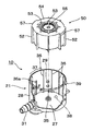
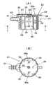
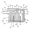
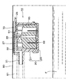
図1〜9は本発明によるフロート弁装置の一実施形態を示し、図1は同弁装置の分解斜視図、図2は同フロート弁装置においてフロート弁体を弁ケース本体に挿入する状態を示す斜視図、図3の(A)は同フロート弁装置の弁ケース本体を示す縦断面図、(B)はI−I矢示線に沿った断面図、図4の(A)はフロート弁体の平面図、(B)はII−II矢示線に沿った断面図、(C)はIII−III矢示線に沿った断面図、図5は同フロート弁装置の縦断面図、図6は燃料タンク内に配置された同フロート弁装置の弁が開いた状態を示す説明図、図7は燃料タンク内に配置された同フロート弁装置の弁が閉じた状態を示す説明図、図8はフロート弁体の突部と弁ケースの連通孔とを示す部分拡大断面図、図9の(A)はフロート弁体の突部の真円度とゲート位置との関係を示す説明図、(B)は弁ケースの連通孔の真円度とゲート位置との関係を示す説明図である。
【0018】
図1に示すように、このフロート弁装置10は、弁ケース本体21と蓋体22とからなる弁ケース20と、この弁ケース20内に収容されるフロート弁体50と、このフロート弁体50に上向きの付勢力を付与するスプリング69とで構成されている。
【0019】
弁ケース本体21は、全体として、上面が閉塞され、下面が開口された円筒状をなし、上壁27には、例えば燃料タンク内壁などに取付けられた固定金具70に挿入されるブラケット23が形成されている。このブラケット23は、弁ケース本体21の上壁27に対して所定の隙間をもって平行に取付けられた舌片部24と、この舌片部24の一端から延出された突出片25と、この突出片25の先端部下面に突出する爪部26とで構成されている。
【0020】
一方、固定金具70は、燃料タンク内壁などに溶着等の手段で固着される両側部71と、この両側部71から折曲形成され、燃料タンク内壁などに対して所定の隙間を設けた中央部72と、この中央部72の一辺からU字状にカットされた切欠き部73とを有している。そして、ブラケット23の突出片25を上記切欠き部73に向けて差し込むと、舌片部24が上記切欠き部73の両側縁部に係合し、かつ、突出片25の爪部26が切欠き部73に対向する辺74に係合して抜け止めがなされる。
【0021】
弁ケース本体21の周壁28には、複数の透孔29が形成されており、弁室30内に燃料等の液体が出入りできるようになっている。また、周壁28の一箇所には図示しない配管が連結される導出管31が一体に形成されている。この導出管31の基端側は、上壁27の上方に形成された隔室32に連通している。隔室32は、上記上壁27と、この上壁27上からリブ状に形成された周壁33と、これらの上部を閉塞する天壁34とで囲まれた空間をなしている。
【0022】
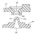
弁ケース本体21の上壁27の中央には、弁室30と隔室32とを連通させる連通孔35が形成されている。この連通孔35は、上下方向から見て円形をなしている。また、この連通孔35の下端開口部の内周35aは、後述するフロート弁体50の突部51が密接するように、上方に向けて縮径するテーパ状をなしている。
【0023】
なお、上壁27のうち、上記隔室32内に配置された部分が、本発明における仕切り壁部を構成している。しかし、用途によっては、上記隔室32は必ずしも必要ではなく、弁ケース本体21の上壁27に連通孔が露出した形状であってもよい。
【0024】
弁ケース本体21の内周には、上下方向に伸びるリブ36が周方向に所定間隔で平行に形成されている。これらのリブ36の頂部は、後述するフロート弁体50の外周に摺接し、フロート弁体50の昇降動作をガイドする。これらのリブ36の間隔は、基本的には一定の間隔をなしているが、半径方向に対向する一対のリブ36aが、それらの下端を短くされており、その結果、リブ36aが途中で切れた部分におけるリブ36の間隔37は、他の部分におけるリブ36の間隔の約2倍となっている。リブ36aの下端位置は、後述するフロート弁体50の昇降動作を妨げない範囲で、できるだけ長くされている。
【0025】
なお、図3(B)における38は、射出成形時のゲートの位置を表している。また、弁ケース本体21の下縁部外周には、蓋体22を係合させるための爪39が所定角度ずつ離れて複数箇所に形成されている。
【0026】
一方、蓋体22は、円形の底壁40と、上記弁ケース本体21の下縁部外周に被さる周壁41とを有している。底壁40には、燃料等の液体が自由に進入できるようにするための複数の透孔42が形成されている。また、スプリング69の下面を安定して支持するための位置決め用のリブ44が形成されている。更に、周壁41には、弁ケース本体21の下縁部外周に被せられたとき、上記爪39が嵌合する係合孔45が形成されている。
【0027】
次に、フロート弁体50は、全体として大略円柱状をなし、その外周には上下に伸びるリブ52が、周方向に所定間隔で平行に形成されている。言い換えるとリブ52は、上下に伸びると共に、フロート弁体50の外周から放射状に突出するように形成されている。リブ52の頂部は、弁ケース本体21の内周に摺接して、フロート弁体50の昇降動作をガイドする。
【0028】
リブ52の上端52aは、上方にやや突出し、フロート弁体50が上昇したとき、弁ケース本体21の上壁27に当接してフロート弁体50の傾きを是正し、突部51が連通孔35に垂直に入るようにしている。また、リブ52の上端52aが上壁27に当接することにより、フロート弁体50と上壁27との間に隙間が確保されるので、フロート弁体50の突部51が連通孔35から離れて弁を開くとき、フロート弁体50が上壁27から離れやすくなる。
【0029】
このリブ52の内側には、フロート弁体50を上下に貫通するスリット53が形成されている。このスリットは、フロート弁体50の上下空間に入った燃料等の液体を自由に行き来させて、フロート弁体50と弁ケース本体21との間で、フロート弁体50の動作がスムーズになされるようにしている。
【0030】
また、フロート弁体50の底壁54の中心には、突部51の近傍まで達する孔55が形成されており、この孔55によって突部51の壁厚を一定にして、射出成形時におけるヒケの発生を抑制し、突部51の成形精度を高めている。更に、フロート弁体50の底壁54から高さ方向中間まで延びる環状の凹部56が形成されている。この環状の凹部56には、前記スプリング69が挿入されて、スプリング69が安定して保持されるようになっている。
【0031】
なお、スプリング69は、フロート弁体50が燃料等の液体に所定高さまで浸漬していない場合には、フロート弁体50の質量によって圧縮された状態、すなわちフロート弁体50が蓋体22の底壁40に当接する状態をなし、フロート弁体50が燃料等の液体に所定高さまで浸漬すると、浮力の助けを借りてフロート弁体50を押し上げることができるように、その付勢力を調整されている。
【0032】
そして、フロート弁体50の上記リブ52間のうち、半径方向に対向する2箇所には、隣接する2つのリブ52を連結するように底壁54の外周から突出する突部57が形成されている。図2に示すように、この突部57は、前記弁ケース本体21のリブ36aが途中で切れた部分におけるリブ36の間隔37に挿入される。また、突部57は、リブ36の他の部分の間隔に入らないので、組み立て時の組付け角度の誤りを防止すると共に、弁ケース本体21に対するフロート弁体50の挿入角度を予め定められた角度に規定することになる。更に、突部57は、上記間隔37内で隣接するリブ36に当接することによって回転を規制されるので、フロート弁体50が昇降動作する際にその回転を規制する。
【0033】
なお、図1において、フロート弁体50の上面における符号58は、フロート弁体50を射出成形する際のゲート位置を表している。
【0034】
本発明の特徴とするところは、上記弁ケース本体21のゲート位置38と、上記フロート弁体50のゲート位置58に基づく、連通孔35の真円度の変形方向と、突部51の真円度の変形方向とが、ほぼ合致するように、上記フロート弁体50の弁ケース本体21に対する角度、すなわち突部57が間隔37に挿入されることにより定められる角度を設定したことにある。ここで、真円度の測定は、真円度測定機を用いた半径法によってなされる。
【0035】
図9は、射出成形されたフロート弁体50の突部51と弁ケース本体21の連通孔35との真円度を、真円度測定機(商品名「ラウンドテスト」、ミツトヨ製)を用いて測定した結果を示し、(A)はフロート弁体50の突部51の真円度を表す図表、(B)は弁ケース本体21の連通孔35との真円度を表す図表である。図9中のGはそれぞれのゲート位置を表している。
【0036】
ここで、本発明における真円に対する変形方向とは、真円度がもっとも大きく変化している方向、例えば真円に対して最も大きく突出している方向を意味し、上記(A)のフロート弁体の場合は図中矢印Lの方向であり、(B)の弁ケース本体の場合は図中矢印Mの方向である。そして、本発明では、上記矢印L方向と、上記矢印M方向とのなす角度が、20度以内、好ましくは10度以内、更に好ましくは5度以内となるように、弁ケース本体21に対するフロート弁体50の角度が設定される。
【0037】
なお、上記真円度の変形は、ゲート位置に起因するものであるため、同じ金型で成形されるそれぞれの部品は、いずれも同じような傾向になる。
【0038】
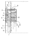
図6,7は、上記フロート弁装置10を自動車の燃料タンクにおける燃料遮断弁に適用した例を示している。同図において、80は燃料タンクの上壁であり、Fは燃料である。固定金具70は予め燃料タンク上壁80に溶着されており、フロート弁装置10は、この固定金具70を介して前記の態様で燃料タンク上壁80の内面に取付けられている。フロート弁装置10の導出管31には、配管81が接続され、この配管81は、燃料タンクの外部に導出されて、図示しないキャニスター等に連結されている。
【0039】
図6に示すように、フロート弁装置10が燃料Fの液面に浸漬していない、あるいは浸漬していてもフロート弁体50に対して所定の高さを超えていない状態では、フロート弁体50の質量によってスプリング69が圧縮され、フロート弁体50は弁ケース本体21の上壁27から離れ、連通孔35は開かれている。その結果、燃料タンク内に充満する燃料蒸気が連通孔35から隔室32、配管81を通って、図示しないキャニスター等に送られる。
【0040】
そして、図7に示すように、燃料Fを補充することにより、あるいは、自動車の走行による燃料Fの揺動や傾きにより、燃料Fの液面が上昇して、フロート弁体50が燃料Fに所定高さ以上浸漬すると、フロート弁体50に浮力が作用するので、この浮力と前記スプリング69の付勢力とによって、フロート弁体50が浮き上がり、弁ケース本体21の上壁27に当接する。その結果、フロート弁体50の突部51が連通孔35を閉塞し、燃料Fが隔室32に流入することを阻止して、配管81内に燃料が流れることを防止する。
【0041】
本発明では、このとき、フロート弁体50の突部57が、弁ケース本体21のリブ36の幅の広い部分37に挿入され、弁ケース本体21に対するフロート弁体50の角度が規制されており、この角度は、前述したように、連通孔35の真円度の変形方向と、突部51の真円度の変形方向とが、特定の角度範囲で合致するように設定されているので、突部51外周と連通孔35内周とのシール性が向上し、燃料Fの漏れをより確実に防止することができる。
【0042】
本実施の形態では、リブ36の幅の広い部分37と、フロート弁体50の突部57とを、それぞれ2つ設けたが、これらは、少なくとも1つずつ有ればよく、また、リブを弁ケース内周とフロート弁体外周の一方に設け、突部を他方に設ければよいものである。
【0043】
【実施例】
図1〜9に示したフロート弁装置を製造し、フロート弁体50の突部51の真円度と、弁ケース本体21の連通孔35の真円度とを、真円度測定機(商品名「ラウンドテスト」、ミツトヨ製)を用いて前述した方法によって測定し、それらの変形方向が正確に合致する場合と、90度交差する場合とで、静的シール性がどの程度異なるかを試験した。
【0044】
静的シール性の測定は、流量計(フローテスター)を用いて、図10の方法によって行った。すなわち、圧力タンク100内にフロート弁装置10を逆さにして配置し、導出管31に接続した配管101を圧力タンク100内から気密的にシールされた状態で取出し、この配管101に流量計102を接続する。また、圧力タンク100には、圧力計103と、加圧機104とを接続する。この状態で、加圧機104からエアーを導入して、圧力タンク100内の圧力を上昇させ、流量計102によってフロート弁装置10からのエアー漏れ量を測定することによって行った。測定試験は5つのサンプルについて行い、それらの平均、最大、最小を求めた。その結果を表1に示す。
【0045】
【表1】
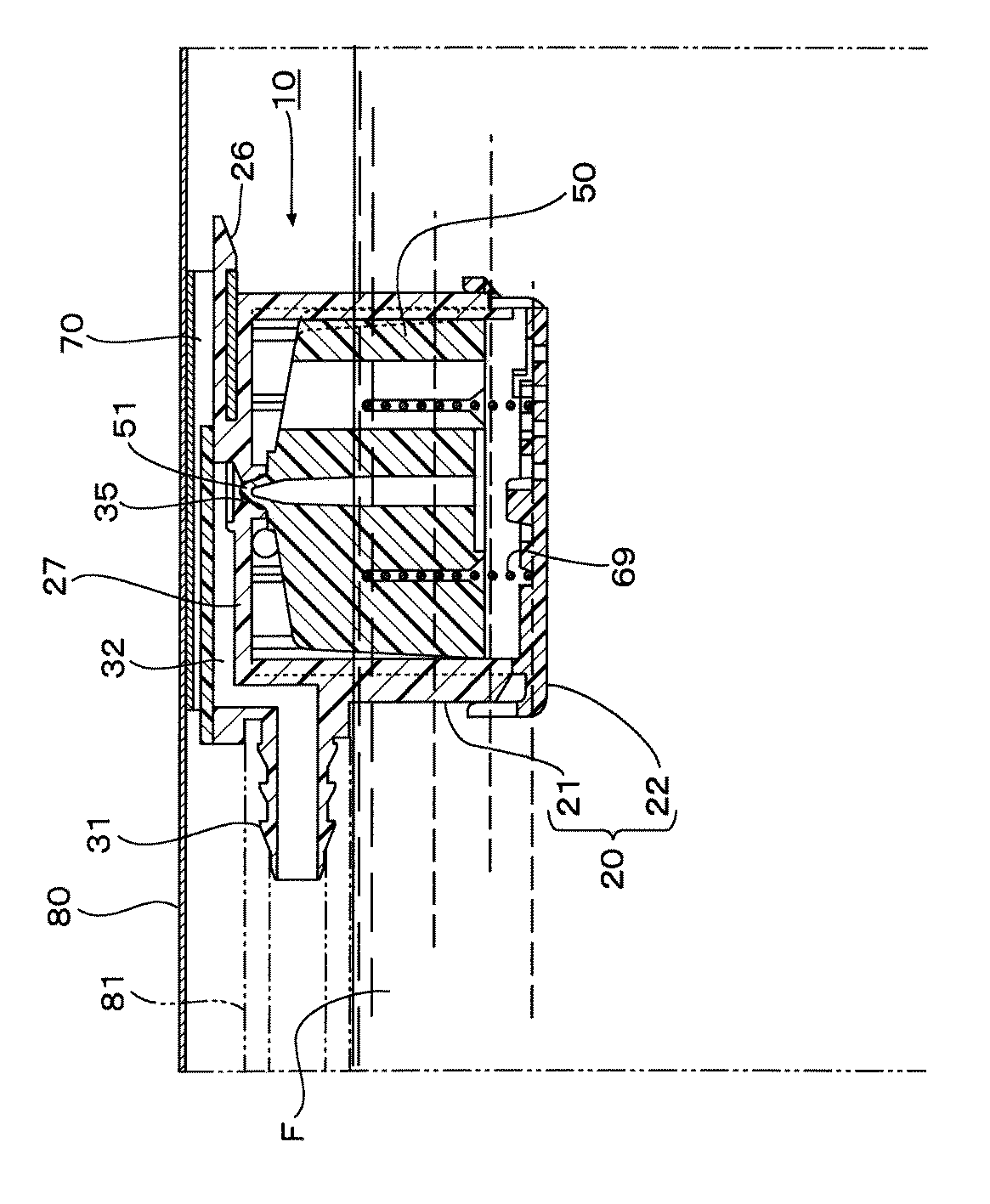
表1の結果から、フロート弁体50の突部51の真円度の変形方向と、弁ケース本体21の連通孔35の真円度の変形方向とを合致させたものは、それらの変形方向を90度で交差するようにしたものに比べて、いずれも流量が著しく少なくなっており、シール性が著しく向上することがわかる。
【0047】
【発明の効果】
以上説明したように、本発明によれば、弁ケースの連通孔内周の、射出成形時のゲート位置に起因する真円に対する変形方向と、フロート弁体の突部外周の、射出成形時のゲート位置に起因する真円に対する変形方向とがほぼ合致するように、フロート弁体の弁ケースに対する角度を設定し、弁ケースとフロート弁体との間に、フロート弁体が昇降動作する際に、フロート弁体の弁ケースに対する角度が上記許容角度を超えて変化しないようにする角度規制手段を設けたので、フロート弁体の突部は、弁ケースの連通孔内周に、それぞれの真円に対する変更方向が合致する角度で当接し、閉塞時のシール面の密着性をより向上させて、液体の漏れをより確実に防止することができる。
【図面の簡単な説明】
【図1】本発明の一実施形態によるフロート弁装置の分解斜視図である。
【図2】同フロート弁装置においてフロート弁体を弁ケース本体に挿入する状態を示す斜視図である。
【図3】 (A)は同フロート弁装置の弁ケース本体を示す縦断面図、(B)はI−I矢示線に沿った断面図である。
【図4】(A)はフロート弁体の平面図、(B)はII−II矢示線に沿った断面図、(C)はIII−III矢示線に沿った断面図である。
【図5】同フロート弁装置の縦断面図である。
【図6】燃料タンク内に配置された同フロート弁装置の弁が開いた状態を示す説明図である。
【図7】燃料タンク内に配置された同フロート弁装置の弁が閉じた状態を示す説明図である。
【図8】フロート弁体の突部と弁ケースの連通孔とを示す部分拡大断面図である。
【図9】(A)はフロート弁体の突部の真円度とゲート位置との関係を示す説明図、(B)は弁ケースの連通孔の真円度とゲート位置との関係を示す説明図である。
【図10】フロート弁装置の静的シール性の測定方法を示す説明図である。
【符号の説明】
10 フロート弁装置
20 弁ケース
21 弁ケース本体
22 蓋体
27 上壁
28 周壁
29 透孔
30 弁室
31 導出管
32 隔室
36 リブ
36a 途中で切れたリブ
37 幅の広い間隔
35 連通孔
38 ゲート
50 フロート弁体
51 突部
52 リブ
57 突部
69 スプリング[0001]
BACKGROUND OF THE INVENTION
The present invention relates to a float valve device suitable for, for example, a fuel cutoff valve that prevents fuel from flowing out of a fuel tank when the liquid level of a fuel tank of an automobile rises.
[0002]
[Prior art]
As a conventional clip of this type, for example, in Patent Document 1 below, a case main body forming a valve chamber connected to a communication passage for communicating the inside of a fuel tank to the outside, and the upper portion of the case body are housed in the valve chamber. A float that opens and closes the communication passage at the closing portion by moving up and down by increasing or decreasing buoyancy with the liquid fuel in the fuel tank entering and exiting the valve chamber. In the fuel cut-off valve provided with a valve body, the float valve body includes a cylindrical float body that forms a float chamber, and fins that protrude from the outer wall portion of the float body along the vertical direction. A plurality of fins spaced apart from each other in the circumferential direction of the float body, and the tops of the fins slide on the inner wall surface of the valve chamber to guide the float body in the vertical direction. An air passage for venting the upper and lower spaces of the valve chamber formed between the guide portion and the fin and partitioned by the float body; and an outer wall portion of the float body; and between the fins There is disclosed a fuel cut-off valve characterized by comprising a throttle forming step portion that projects and forms a throttle portion that narrows a part of the air passage.
[0003]
In Patent Document 2 below, an internal hollow valve body provided in the upper part of a tank for storing liquid, and the liquid level in the tank inserted into the hollow inside of the valve body and flowing into the valve body are vertically A valve body that moves, a passage that communicates the inside and outside of the tank that opens to the top of the valve body, and a valve seat that is provided in the opening of the passage. The valve body includes a float and the float And a valve disc having a valve portion that is held relative to the float at the upper portion of the valve body, and that forms the valve body in accordance with the height of the liquid level flowing into the valve body. In the liquid shut-off valve that opens and closes the passage by contacting and separating from the valve seat, the valve disk is held on the top of the float so as to be tiltable by a plurality of pawls, and among the plurality of pawls One pawl is made shorter than the other pawl, and a protrusion is provided on the opposite side of the short pawl to the center of the valve seat from the upper part of the valve body so that the upper surface of the valve disc contacts when the valve is opened. A liquid shut-off valve is disclosed. In this liquid shut-off valve, a concave portion extending vertically is provided on the side wall of the float, and a protrusion that fits into the concave portion is provided on the inner periphery of the valve body to constitute a means for preventing rotation of the float relative to the valve body. Yes.
[0004]
[Patent Document 1]
Japanese Patent No. 3257437 [Patent Document 2]
JP-A-8-2225022
[Problems to be solved by the invention]
In the fuel cut-off valve disclosed in Patent Document 1, a plurality of fins protruding in the vertical direction on the outer periphery of the float body are provided in parallel at predetermined intervals, and the tops of these fins are provided on the inner wall surface of the valve chamber. However, it does not have a means for preventing rotation of the float body relative to the case body.
[0006]
In the liquid shut-off valve disclosed in Patent Document 2, a float extending vertically is provided on the side wall of the float, and a protrusion that fits into the recess is provided on the inner periphery of the valve body, thereby rotating the float with respect to the valve body. Stop means are provided. However, this anti-rotation means is provided to prevent the protrusion provided on the upper part of the valve body from interfering with the pawl provided on the upper part of the float.
[0007]
On the other hand, these float valve devices are generally manufactured by injection molding a synthetic resin. In addition, these float valve devices are closed so that the protrusion provided on the upper part of the float valve body is inserted into and closely contacted with the communication hole provided on the upper wall or the partition wall of the valve case. It has become. However, depending on the gate position at the time of injection molding, the outer periphery of the protrusion of the float valve body and the inner periphery of the communication hole of the valve case tend to be deformed in a predetermined direction from the designed perfect circular shape.
[0008]
However, until now, no consideration has been given to such deformation due to the gate position. For this reason, there is a problem that a gap is generated on the seal surface due to insufficient roundness, and liquid leakage occurs.
[0009]
Accordingly, it is an object of the present invention to provide a float valve device that improves the adhesion of the seal surface when the valve is closed to minimize the occurrence of liquid leakage.
[0010]
[Means for Solving the Problems]
In order to achieve the above object, a first aspect of the present invention includes a valve case and a float valve body disposed so as to be movable up and down in the valve case, and the valve case and the float valve body are made of resin injection molding. The valve case has a valve chamber in which the float valve element is disposed, a partition wall portion formed in an upper portion of the valve chamber, and a communication hole formed in the partition wall portion, In the float valve, the float valve body has a protrusion that moves up and down according to the liquid level of the liquid flowing into the valve chamber and closes the communication hole when contacting the partition wall. Deformation direction of the inner circumference of the communication hole of the valve case with respect to the perfect circle due to the gate position during injection molding, and deformation of the outer periphery of the protrusion of the float valve body with respect to the perfect circle due to the gate position during injection molding The float so that the direction almost matches An angle of the body with respect to the valve case is set, and when the float valve body moves up and down between the valve case and the float valve body, the angle of the float valve body with respect to the valve case is the allowable angle. The angle restricting means is provided so as not to change beyond the upper limit, and the angle restricting means includes a plurality of parallel ribs extending in the vertical direction formed on one of the inner periphery of the valve case and the outer periphery of the float valve body. A protrusion formed on the other of the inner periphery of the valve case and the outer periphery of the float valve body and inserted between adjacent ribs. The float valve device is characterized in that it is wider than the interval between adjacent ribs, and the protrusion is configured so as not to be inserted between other ribs.
[0011]
According to the above invention, the deformation direction of the inner periphery of the communication hole of the valve case with respect to the perfect circle caused by the gate position at the time of injection molding, and the true direction caused by the gate position at the time of injection molding of the outer periphery of the protrusion of the float valve body The angle of the float valve body with respect to the valve case is set so that the deformation direction with respect to the circle substantially matches, and when the float valve body moves up and down between the valve case and the float valve body, the valve of the float valve body Since the angle restricting means for preventing the angle with respect to the case from changing beyond the allowable angle is provided, the projecting portion of the float valve body is aligned with the inner circumference of the communication hole of the valve case and the direction of change with respect to each perfect circle. Contact at an angle makes it possible to improve the adhesion of the sealing surface at the time of closing and prevent liquid leakage more reliably.
[0013]
In addition, the lifting and lowering operation of the float valve body is guided by a plurality of vertically extending ribs formed on one of the valve case inner periphery and the float valve body outer periphery, and the gap between the ribs is widened. When the float valve body is assembled into the valve case by the protrusions inserted only at intervals, the float valve body can always be assembled at a predetermined angle with respect to the valve case. Further, when the float valve body moves up and down, the protrusion moves in a state in which the position is regulated between the ribs, so that the angle of the float valve body with respect to the valve case does not change.
[0014]
According to a second aspect of the present invention, in the first aspect, the rib is formed on the inner periphery of the valve case, the protrusion is formed on the outer periphery of the float valve body, and the protrusion on the inner periphery of the valve case. A float valve device is provided in which ribs are partially formed only in the upper direction within a range that does not hinder the lifting and lowering operation of the float valve body.
[0015]
According to the above invention, the protrusion provided on the float valve body is disposed at a wide rib interval on the inner periphery of the valve case, so that the angle of the float valve body with respect to the valve case is regulated, and the rib interval In the wide portion, the rib is partially formed only in the upper direction as long as the lifting and lowering operation of the float valve body is not hindered, so that the rigidity of the valve case can be increased as much as possible.
[0016]
DETAILED DESCRIPTION OF THE INVENTION
Hereinafter, embodiments of the present invention will be described with reference to the drawings.
[0017]
1 to 9 show an embodiment of a float valve device according to the present invention, FIG. 1 is an exploded perspective view of the valve device, and FIG. 2 shows a state in which a float valve body is inserted into a valve case body in the float valve device. 3A is a longitudinal sectional view showing a valve case main body of the float valve device, FIG. 3B is a sectional view taken along a line I-I, and FIG. 4A is a float valve body. (B) is a sectional view taken along the line II-II, (C) is a sectional view taken along the line III-III, FIG. 5 is a longitudinal sectional view of the float valve device, FIG. Is an explanatory view showing a state in which the valve of the float valve device arranged in the fuel tank is opened, FIG. 7 is an explanatory view showing a state in which the valve of the float valve device arranged in the fuel tank is closed, FIG. Is a partially enlarged sectional view showing the protrusion of the float valve body and the communication hole of the valve case. FIG. 9A is a protrusion of the float valve body. Explanatory view showing a relationship between the roundness and the gate position of, (B) is an explanatory diagram showing the relationship between circularity and gate position of the communicating hole of the valve case.
[0018]
As shown in FIG. 1, the
[0019]
The
[0020]
On the other hand, the fixing
[0021]
A plurality of through
[0022]
A
[0023]
In addition, the part arrange | positioned in the said
[0024]
On the inner periphery of the valve case
[0025]
Note that
[0026]
On the other hand, the
[0027]
Next, the
[0028]
The
[0029]
A
[0030]
Further, a
[0031]
The
[0032]
And the
[0033]
In FIG. 1,
[0034]
The features of the present invention are that the rounding direction of the
[0035]
FIG. 9 shows a roundness measuring device (trade name “Round Test”, manufactured by Mitutoyo Corporation) for the roundness between the
[0036]
Here, the deformation direction with respect to the perfect circle in the present invention means the direction in which the roundness changes most greatly, for example, the direction in which the roundness protrudes the most with respect to the perfect circle. Is the direction of arrow L in the figure, and in the case of the valve case main body of (B), it is the direction of arrow M in the figure. In the present invention, the float valve with respect to the valve case
[0037]
Since the roundness deformation is caused by the gate position, all the parts molded by the same mold have the same tendency.
[0038]
6 and 7 show an example in which the
[0039]
As shown in FIG. 6, when the
[0040]
Then, as shown in FIG. 7, when the fuel F is replenished, or the fuel F swings or tilts as the vehicle travels, the liquid level of the fuel F rises, and the
[0041]
In the present invention, at this time, the
[0042]
In the present embodiment, two
[0043]
【Example】
The float valve device shown in FIGS. 1 to 9 is manufactured, and the roundness of the
[0044]
The static sealability was measured by a method shown in FIG. 10 using a flow meter (flow tester). That is, the
[0045]
[Table 1]
From the results of Table 1, the deformation direction of the roundness of the
[0047]
【The invention's effect】
As described above, according to the present invention, the deformation direction of the inner circumference of the communication hole of the valve case with respect to the perfect circle caused by the gate position at the time of injection molding and the outer periphery of the protrusion of the float valve body at the time of injection molding. When the float valve body moves up and down between the valve case and the float valve body, the angle of the float valve body with respect to the valve case is set so that the deformation direction with respect to the perfect circle caused by the gate position is almost the same. Since the angle restricting means is provided so that the angle of the float valve body with respect to the valve case does not change beyond the allowable angle, the protrusion of the float valve body has a respective round shape on the inner periphery of the communication hole of the valve case. The contact direction is changed at an angle that matches the change direction, and the adhesion of the sealing surface at the time of closing can be further improved to prevent liquid leakage more reliably.
[Brief description of the drawings]
FIG. 1 is an exploded perspective view of a float valve device according to an embodiment of the present invention.
FIG. 2 is a perspective view showing a state in which the float valve body is inserted into the valve case body in the float valve device.
3A is a longitudinal sectional view showing a valve case main body of the float valve device, and FIG. 3B is a sectional view taken along the line I-I.
4A is a plan view of a float valve body, FIG. 4B is a cross-sectional view taken along the line II-II, and FIG. 4C is a cross-sectional view taken along the line III-III.
FIG. 5 is a longitudinal sectional view of the float valve device.
FIG. 6 is an explanatory view showing a state in which the valve of the float valve device arranged in the fuel tank is opened.
FIG. 7 is an explanatory view showing a state in which the valve of the float valve device arranged in the fuel tank is closed.
FIG. 8 is a partially enlarged sectional view showing a protrusion of the float valve body and a communication hole of the valve case.
9A is an explanatory view showing the relationship between the roundness of the protrusion of the float valve element and the gate position, and FIG. 9B shows the relationship between the roundness of the communication hole of the valve case and the gate position. It is explanatory drawing.
FIG. 10 is an explanatory view showing a method for measuring the static sealing performance of the float valve device.
[Explanation of symbols]
DESCRIPTION OF
Claims (2)
前記弁ケースの前記連通孔内周の、射出成形時のゲート位置に起因する真円に対する変形方向と、前記フロート弁体の前記突部外周の、射出成形時のゲート位置に起因する真円に対する変形方向とがほぼ合致するように、前記フロート弁体の前記弁ケースに対する角度が設定され、
前記弁ケースと前記フロート弁体との間には、前記フロート弁体が昇降動作する際に、前記フロート弁体の前記弁ケースに対する角度が前記許容角度を超えて変化しないようにする角度規制手段が設けられており、
前記角度規制手段は、前記弁ケース内周と前記フロート弁体外周の一方に形成された上下方向に伸びる複数の平行なリブと、前記弁ケース内周と前記フロート弁体外周の他方に形成され、隣接するリブの間に挿入される突部とを有し、
前記突部が挿入される隣接するリブの間隔は、他の隣接するリブの間隔よりも幅広くされており、前記突部は、他のリブの間には挿入できないように構成されていることを特徴とするフロート弁装置。A valve case and a float valve body disposed in the valve case so as to be movable up and down. The valve case and the float valve body are made of a resin injection-molded product, and the valve case includes the float valve body. A valve chamber disposed in the upper portion of the valve chamber; a communication hole formed in the partition wall portion; and the float valve body configured to store liquid flowing into the valve chamber. In a float valve that has a protrusion that moves up and down according to the liquid level and closes the communication hole when contacting the partition wall,
The deformation direction of the inner periphery of the communication hole of the valve case with respect to the perfect circle due to the gate position at the time of injection molding, and the perfect circle due to the gate position at the time of injection molding of the outer periphery of the protrusion of the float valve body An angle of the float valve body with respect to the valve case is set so that the deformation direction substantially matches,
Between the valve case and the float valve body, an angle regulating means for preventing an angle of the float valve body with respect to the valve case from changing beyond the allowable angle when the float valve body moves up and down. Is provided,
The angle regulating means is formed on the other of the valve case inner periphery and the float valve body outer periphery, and a plurality of parallel ribs extending in the vertical direction formed on one of the valve case inner periphery and the float valve body outer periphery. A protrusion inserted between adjacent ribs,
The interval between adjacent ribs into which the protrusions are inserted is wider than the interval between other adjacent ribs, and the protrusions are configured so that they cannot be inserted between other ribs. Float valve device characterized.
Priority Applications (2)
| Application Number | Priority Date | Filing Date | Title |
|---|---|---|---|
| JP2003105329A JP4331503B2 (en) | 2003-04-09 | 2003-04-09 | Float valve device |
| US10/820,153 US7032610B2 (en) | 2003-04-09 | 2004-04-08 | Float valve device |
Applications Claiming Priority (1)
| Application Number | Priority Date | Filing Date | Title |
|---|---|---|---|
| JP2003105329A JP4331503B2 (en) | 2003-04-09 | 2003-04-09 | Float valve device |
Related Child Applications (1)
| Application Number | Title | Priority Date | Filing Date |
|---|---|---|---|
| JP2006016517A Division JP4335877B2 (en) | 2006-01-25 | 2006-01-25 | Float valve device |
Publications (2)
| Publication Number | Publication Date |
|---|---|
| JP2004308838A JP2004308838A (en) | 2004-11-04 |
| JP4331503B2 true JP4331503B2 (en) | 2009-09-16 |
Family
ID=33467876
Family Applications (1)
| Application Number | Title | Priority Date | Filing Date |
|---|---|---|---|
| JP2003105329A Expired - Lifetime JP4331503B2 (en) | 2003-04-09 | 2003-04-09 | Float valve device |
Country Status (2)
| Country | Link |
|---|---|
| US (1) | US7032610B2 (en) |
| JP (1) | JP4331503B2 (en) |
Families Citing this family (23)
| Publication number | Priority date | Publication date | Assignee | Title |
|---|---|---|---|---|
| JP4197506B2 (en) * | 2004-08-31 | 2008-12-17 | 株式会社パイオラックス | Cut valve |
| JP2006290085A (en) * | 2005-04-08 | 2006-10-26 | Kyosan Denki Co Ltd | Seal structure of float valve |
| JP2007016891A (en) * | 2005-07-07 | 2007-01-25 | Noritz Corp | Air vent valve |
| JP4603949B2 (en) | 2005-07-29 | 2010-12-22 | 豊田合成株式会社 | Fuel shut-off valve |
| US8291929B2 (en) * | 2006-05-16 | 2012-10-23 | GM Global Technology Operations LLC | Dual float rollover valve |
| US7632449B2 (en) * | 2007-06-04 | 2009-12-15 | Bridgestone Sports Co., Ltd. | Method of manufacturing a golf ball |
| DE102008020538A1 (en) * | 2008-04-24 | 2009-10-29 | GM Global Technology Operations, Inc., Detroit | Tank flap module housing with integrated water drain valve |
| JP5123816B2 (en) * | 2008-10-22 | 2013-01-23 | 株式会社パイオラックス | Float valve device |
| US20100319788A1 (en) * | 2009-06-20 | 2010-12-23 | Ward David P | Separating liquid shut-off for ammonia vapor transfer system |
| USD628273S1 (en) * | 2010-01-12 | 2010-11-30 | Stone Iii Harley E | Float valve fitting |
| JP2013024288A (en) * | 2011-07-19 | 2013-02-04 | Aisan Industry Co Ltd | Fuel cutoff valve |
| NO334569B1 (en) * | 2012-12-21 | 2014-04-14 | Vetco Gray Scandinavia As | Valve device for venting gas from liquid circulating in a subsea production system |
| US9506785B2 (en) | 2013-03-15 | 2016-11-29 | Rain Bird Corporation | Remote flow rate measuring |
| CN103672137B (en) * | 2013-12-20 | 2015-09-09 | 彭小英 | A kind of press-type water tap |
| EP3286485B1 (en) | 2015-04-23 | 2019-12-18 | Graco Minnesota Inc. | Centerfill of lubricant reservoir |
| WO2018013857A1 (en) | 2016-07-13 | 2018-01-18 | Rain Bird Corporation | Flow sensor |
| US10473494B2 (en) | 2017-10-24 | 2019-11-12 | Rain Bird Corporation | Flow sensor |
| US11662242B2 (en) | 2018-12-31 | 2023-05-30 | Rain Bird Corporation | Flow sensor gauge |
| CN110886851A (en) * | 2019-12-25 | 2020-03-17 | 艾坦姆流体控制技术(北京)有限公司 | A regulating valve that can meet the bubble-level leakage under hard sealing |
| GB2610754B (en) * | 2020-06-15 | 2024-12-11 | Piolax Inc | Valve device |
| EP3988367B1 (en) * | 2020-10-23 | 2023-05-03 | Magna Energy Storage Systems GesmbH | Tank for a motor vehicle |
| JP7442698B2 (en) * | 2021-02-02 | 2024-03-04 | 株式会社パイオラックス | valve device |
| US12443208B2 (en) | 2023-02-08 | 2025-10-14 | Rain Bird Corporation | Control zone devices, systems and methods |
Family Cites Families (3)
| Publication number | Priority date | Publication date | Assignee | Title |
|---|---|---|---|---|
| JP3419137B2 (en) | 1995-02-20 | 2003-06-23 | エヌオーケー株式会社 | Liquid shutoff valve |
| JP3257437B2 (en) | 1997-03-05 | 2002-02-18 | 豊田合成株式会社 | Fuel cutoff valve |
| JP2002147632A (en) * | 2000-08-29 | 2002-05-22 | Nifco Inc | Valve device |
-
2003
- 2003-04-09 JP JP2003105329A patent/JP4331503B2/en not_active Expired - Lifetime
-
2004
- 2004-04-08 US US10/820,153 patent/US7032610B2/en not_active Expired - Fee Related
Also Published As
| Publication number | Publication date |
|---|---|
| JP2004308838A (en) | 2004-11-04 |
| US20040261846A1 (en) | 2004-12-30 |
| US7032610B2 (en) | 2006-04-25 |
Similar Documents
| Publication | Publication Date | Title |
|---|---|---|
| JP4331503B2 (en) | Float valve device | |
| JP2611785B2 (en) | Fuyer Cap | |
| US7163023B2 (en) | Fuel vapor vent valve float assembly and method of making same | |
| US7527064B2 (en) | Fuel cutoff valve | |
| JP6886434B2 (en) | Fuel tank valve gear | |
| AU2004203821B2 (en) | Fuel vapor vent valve and method of attaching same to a tank | |
| JP5421465B2 (en) | Cap mounting structure | |
| JP4335877B2 (en) | Float valve device | |
| JP2001329925A (en) | Fuel cut-off valve device | |
| JP3928062B2 (en) | Float valve | |
| JP5949686B2 (en) | In-tank valve unit | |
| JP2023070221A (en) | Full tank regulation valve | |
| JP7240522B2 (en) | valve device | |
| US20220194216A1 (en) | Over-fueling prevention valve | |
| JP4197506B2 (en) | Cut valve | |
| CN100340801C (en) | Float valve device | |
| JP4688274B2 (en) | Fuel tank connector | |
| JP2020050233A (en) | Opening/closing device for fuel tank | |
| JPH0622138U (en) | Reservoir for master cylinder | |
| JPH0749029A (en) | Radiator for automobile | |
| JPH0740237U (en) | Tank cap |
Legal Events
| Date | Code | Title | Description |
|---|---|---|---|
| A621 | Written request for application examination |
Free format text: JAPANESE INTERMEDIATE CODE: A621 Effective date: 20050729 |
|
| A977 | Report on retrieval |
Free format text: JAPANESE INTERMEDIATE CODE: A971007 Effective date: 20081017 |
|
| A131 | Notification of reasons for refusal |
Free format text: JAPANESE INTERMEDIATE CODE: A131 Effective date: 20081111 |
|
| A521 | Request for written amendment filed |
Free format text: JAPANESE INTERMEDIATE CODE: A523 Effective date: 20090109 |
|
| TRDD | Decision of grant or rejection written | ||
| A01 | Written decision to grant a patent or to grant a registration (utility model) |
Free format text: JAPANESE INTERMEDIATE CODE: A01 Effective date: 20090602 |
|
| A01 | Written decision to grant a patent or to grant a registration (utility model) |
Free format text: JAPANESE INTERMEDIATE CODE: A01 |
|
| A61 | First payment of annual fees (during grant procedure) |
Free format text: JAPANESE INTERMEDIATE CODE: A61 Effective date: 20090618 |
|
| R150 | Certificate of patent or registration of utility model |
Ref document number: 4331503 Country of ref document: JP Free format text: JAPANESE INTERMEDIATE CODE: R150 Free format text: JAPANESE INTERMEDIATE CODE: R150 |
|
| FPAY | Renewal fee payment (event date is renewal date of database) |
Free format text: PAYMENT UNTIL: 20120626 Year of fee payment: 3 |
|
| FPAY | Renewal fee payment (event date is renewal date of database) |
Free format text: PAYMENT UNTIL: 20130626 Year of fee payment: 4 |
|
| FPAY | Renewal fee payment (event date is renewal date of database) |
Free format text: PAYMENT UNTIL: 20130626 Year of fee payment: 4 |
|
| EXPY | Cancellation because of completion of term |