JP4331502B2 - Sealed structure - Google Patents
Sealed structure Download PDFInfo
- Publication number
- JP4331502B2 JP4331502B2 JP2003103577A JP2003103577A JP4331502B2 JP 4331502 B2 JP4331502 B2 JP 4331502B2 JP 2003103577 A JP2003103577 A JP 2003103577A JP 2003103577 A JP2003103577 A JP 2003103577A JP 4331502 B2 JP4331502 B2 JP 4331502B2
- Authority
- JP
- Japan
- Prior art keywords
- contact
- flat surface
- metal seal
- contact flat
- surface portion
- Prior art date
- Legal status (The legal status is an assumption and is not a legal conclusion. Google has not performed a legal analysis and makes no representation as to the accuracy of the status listed.)
- Expired - Lifetime
Links
Images


Landscapes
- Gasket Seals (AREA)
Description
【0001】
【発明の属する技術分野】
本発明は、金属シールを用いた密封構造体に関する。
【0002】
【従来の技術】
従来からシール材としてゴム製Oリングが広く使用されているが、高温、低温、ゴム腐食ガス環境等では使用できない場合がある。そこで、従来から以下の(1)〜 (4)のような金属製のシールが用いられている。即ち、 (1)メタルOリング、 (2)メタルCリング、 (3)バネ入りCリング、 (4)レジェントシール等が使用されている。
【0003】
しかしながら、各々の金属シールには以下のような問題がある。
(1) メタルOリング
最も一般的で実績のある金属シールであり、安定したシール性能が得られるが、締付力が大きく、かつ、復元量が0.05mm程度と小さい等の欠点がある。
(2) メタルCリング
メタルOリングに比べて締付力は小さく、かつ復元量も比較的大きく、0.05mm〜0.15mm程度である。しかしながら、用途(使用条件)によっては、依然、締付力の値が大きく、復元量も不足する。
(3) バネ入りCリング
復元量は0.1 〜0.15mmと大きい。しかしながら、用途(使用条件)によっては復元量が不足する。さらに、コイルバネを包み込むようにCリング本体内に入れるので、製作が面倒で構造が複雑化すると共に、締付力が大きく、コストも高くなる欠点がある。
(4) レジェントシール
他のメタルシールに比べて締付力が小さく、かつ復元量も0.1 〜0.2 mmと大きい。しかし、切削加工であるため、製作が面倒で、非常に高価である。
【0004】
要するに、従来の金属シールでは製作が容易で、締付力が小さく、かつ、弾性的復元量が大きくて、安価であるという全ての条件(要望)を満足させ得るものが、なかった。
【0005】
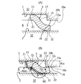
そこで、本発明者等は図9又は図10に示すような、緩やかに弯曲した断面S字状の金属シール41を特願2002−199363にて提案した。即ち、図9又は図10に示すように、相互に平行な第1平坦面46と第2平坦面47の間に、全体が環状の金属シール41が介装される。第1平坦面46と第2平坦面47が矢印F1 ,F2 のように金属シール41を押圧すると金属シール41は中間基部42を中心に矢印M1 の如く捩れ弾性変形を生じて、第1接触凸部43と第2接触凸部44が弾発的に接触して密封(シール)作用をなす構造である。
【0006】
このように、締付力(矢印F1 ,F2 参照)が小さく、復元性に優れた金属シール41を提案したのであったが、しかし、流体圧力P…が高い使用条件───例えば10MPa以上の圧力───では、図9(A)の矢印Z方向に、第2接触凸部44が第2平坦面47から浮上り、矢印E方向に流体洩れ(ブローバイ)を発生するという問題があることが、判明した。
即ち、図9(A)中に矢印Zにて示すように金属シール41に高圧の流体圧力P…が作用し、比較的小さな締付力F1 ,F2 にて捩れ弾性変形している金属シール41は、簡単に矢印Zに浮上る現象を生ずる。
このような問題を解決する方法としては、金属シールの背面全体を押圧する部材を付加する発明が提案されている(例えば、特許文献1参照)。
【0007】
【特許文献1】
特開2001−324021
【0008】
【発明が解決しようとする課題】
ところが、金属シールの背面全体を押圧することは、内燃機関のエンジンのシリンダヘッド用として、極めて高い圧力に耐えうる点で優れているといえども、上述した小さい締付力F1 ,F2 で使用できるという最大のメリットが消失してしまうこととなる。言い換えると、上記特許文献1のような金属シールでは、締付力を増大させるために締付構造やフランジ部等が大型化するといった問題、さらには、金属シールが圧接するフランジの接触面がクリープ現象等で損傷を受けるという問題がある。
【0009】
また、図9(B)に示す如く、図9(A)の状態よりも一層、第1・第2平坦面46, 47を相互に接近させ(間隔Bを極めて小さく設定し)、金属シール41に大きな捩れ弾性変形を生じさせれば、端部48が第1平坦面46に接触し、第1接触凸部43と第2接触凸部44と端部48の3点で、押さえ込まれて、図9(A)にて説明した上記問題(矢印E方向への流体洩れの問題)は解決するが、以下の別の問題が生ずる。
【0010】
つまり、金属シール41に過大な捩れ弾性変形を生じさせる(過大なつぶし量を与える)こととなり、金属シール41が大きく塑性変形を生じたり、金属シール41が圧接するフランジ等の接触面(第1・第2平坦面46, 47)がクリープ現象等で損傷を受けるという問題が生ずる。あるいは、内周側のシール部(即ち第1接触凸部43と第1平坦面46との密接部位)については、図9(B)を図9(A)と比較すれば明らかなように、図9(B)の方の圧力Pの受圧部分の範囲が減少して、密封(シール)性が低下する場合もある。勿論、小さな締付力F1 ,F2 で使用できるという最大のメリットが消失してしまう。
【0011】
また、この種の金属シール41の使用形態としては、金属シール41を図10(A)のように水平状態として使用する場合に限られず、図10(B)に示すように鉛直状態(又はその中間の傾斜状態)にて使われる場合も多い。
金属シール41の取付け時、又は、取外しの際に、この金属シール41が正規位置から位置ずれしたり、脱落したりする虞がある。しかも、捩り弾性変形を利用するこの金属シール41では、圧縮する際に、径方向に僅かに拡大するので、シール溝内面49と隙間50を形成しているため、一層、上記脱落を生じやすく、しかも、シール溝のセンターに合わせにくいという問題を生ずる。
【0012】
本発明は、締付力が小さく、復元性も大きく、従って、締付構造が簡易となり、フランジ部等が肉薄であっても良く、金属シールとの接触面が損傷を受けない密封構造体を提供することを目的とする。特に、高い流体圧力が作用した際にも、優れた密封性(シール性)を発揮する密封構造体を提供することを他の目的とする。また、金属シールの組付けや取外しの際に脱落せず、若しくは、位置ずれしない(センターが合致しやすい)密封構造体を提供することを、別の目的とする。
【0013】
【課題を解決するための手段】
本発明は、相互に平行な第1接触平坦面部と第2接触平坦面部、及び、該第1・第2接触平坦面部の間に介装される全体が環状の金属シールとを、備えた密封構造に於て、上記金属シールは、同一肉厚寸法で緩やかに弯曲した断面S字状であって、中間基部と、上記第1接触平坦面部に接触する第1接触凸部と、上記第2接触平坦面部に接触する第2接触凸部と、を有し、上記第1接触凸部と上記第2接触凸部を内径寄りと外径寄りに異なって配設して、装着圧縮状態にて、上記金属シールは上記中間基部を中心に回転する捩れ弾性変形を生ずると共に、受圧室側の一端部と反対の他端部を上記装着圧縮状態にて押さえる他端押圧部を、上記第1接触平坦面部及び第2接触平坦面部とは相違する平面上に設け、さらに、全体が環状の上記金属シールは、該環状の内側から流体圧力が作用する内圧用であって、上記受圧室は該環状の内側に配設されて、上記第2接触凸部よりも外径側の外周端縁から成る上記他端部を装着圧縮状態にて押さえる上記他端押圧部を、上記第1接触平坦面部側に形成した突出部をもって構成し、しかも、上記金属シールは、装着圧縮状態で上記外周端縁の角部が横断面において点として、上記突出部に接触保持されるように構成した。
【0014】
また、相互に平行な第1接触平坦面部と第2接触平坦面部、及び、該第1・第2接触平坦面部の間に介装される全体が環状の金属シールとを、備えた密封構造に於て、上記金属シールは、同一肉厚寸法で緩やかに弯曲した断面S字状であって、中間基部と、上記第1接触平坦面部に接触する第1接触凸部と、上記第2接触平坦面部に接触する第2接触凸部と、を有し、上記第1接触凸部と上記第2接触凸部を内径寄りと外径寄りに異なって配設して、装着圧縮状態にて、上記金属シールは上記中間基部を中心に回転する捩れ弾性変形を生ずると共に、受圧室側の一端部と反対の他端部を上記装着圧縮状態にて押さえる他端押圧部を、上記第1接触平坦面部及び第2接触平坦面部とは相違する平面上に設け、さらに、全体が環状の上記金属シールは、該環状の外側から流体圧力が作用する外圧用であって、上記受圧室は該環状の外側に配設されて、上記第1接触凸部よりも内径側の内周端縁から成る上記他端部を装着圧縮状態にて押さえる上記他端押圧部を、上記第2接触平坦面部側に形成した突出部をもって構成し、しかも、上記金属シールは、装着圧縮状態で上記内周端縁の角部が横断面において点として、上記突出部に接触保持されるように構成した。
【0015】
また、相互に平行な第1接触平坦面部と第2接触平坦面部、及び、該第1・第2接触平坦面部の間に介装される全体が環状の金属シールとを、備えた密封構造に於て、上記金属シールは、横断面略矩形の中間基部と、上記第1接触平坦面部に接触する横断面略半円形の第1接触凸部と、上記第2接触平坦面部に接触する横断面略半円形の第2接触凸部と、を有し、上記第1接触凸部と上記第2接触凸部を内径寄りと外径寄りに異なって配設して、装着圧縮状態にて、上記金属シールは上記中間基部を中心に回転する捩れ弾性変形を生ずると共に、受圧室側の一端部と反対の他端部を上記装着圧縮状態にて押さえる他端押圧部を、上記第1接触平坦面部及び第2接触平坦面部とは相違する平面上に設け、さらに、全体が環状の上記金属シールは、該環状の内側から流体圧力が作用する内圧用であって、上記受圧室は該環状の内側に配設されて、上記第2接触凸部よりも外径側の外周端縁から成る上記他端部を装着圧縮状態にて押さえる上記他端押圧部を、上記第1接触平坦面部側に形成した突出部をもって構成し、しかも、上記金属シールは、装着圧縮状態で上記中間基部の上記外周端縁側の角部が横断面において点として、上記突出部に接触保持されるように構成した。
また、上記第1接触平坦面部を有する第1部材、及び、上記第2接触平坦面部を有する第2部材とは別部材から成るスペーサをもって、上記他端押圧部を形成した。
【0016】
【発明の実施の形態】
以下、図示の実施の形態に基づき、本発明を詳説する。
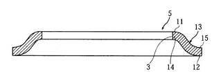
図1は自由状態(未装着状態)の金属シール5の全体の断面正面図であり、図2は密封構造体の一つの実施の形態を示す要部拡大断面図であって、図2(A)は装着未圧縮状態、図2(B)は装着圧縮状態(使用状態)を示す。
【0017】
この金属シール(メタルシール)5は、ステンレス鋼やばね用鋼やその他の金属から成り、薄板材からプレス加工(塑性加工)により形成するのが、製作の容易性とコスト面から好ましいが、切削や研削等の機械加工にて作製することも可能である。また、金属シール5は、その表面に、(図示省略するが、)銀、金、銅、すず等のメッキ被覆や、PTFE,FEP等の各種樹脂被覆や、各種ゴム材料の被覆を、行うも好ましい場合がある。
【0018】
この金属シール5は、全体形状が、円形,略矩形,多角形,長円形,楕円形,雲形等の環状であって、相互に平行な第1接触平坦面部1と第2接触平坦面部2との間に介装されるものであり、本発明に係る密封構造体は、金属シール5と、これが介装される第1・第2接触平坦面部1,2とを、備えている。
さらに、この金属シール5は、中間基部13と、第1接触平坦面部1に接触する第1接触凸部11と、第2接触平坦面部2に接触する第2接触凸部12と、を有し、第1接触凸部11は内径寄りに、第2接触凸部12は外径寄りに、相互に内外径方向に異なった位置に配設されている。
【0019】
具体的に説明すると、第1接触凸部11を有する内周縁14と、拡径テーパ壁状の中間基部13と、第2接触凸部12を有する外周縁15は、同一肉厚寸法で緩やかに弯曲した断面S字状である。そして、本発明で、S字状とは、反転S字状───Z字状───を含むものと定義する。
このように、図1と図2に示す金属シール5は、緩やかに弯曲した弯曲壁にて構成された略円錐台形状であって、第1接触凸部11の存在する内周縁14にて、孔部3が形成されている。
【0020】
そして、図2(A)に示す装着未圧縮状態から図2(B)に示す装着圧縮状態に変化してゆくに従って、金属シール5は中間基部13を中心に、矢印M1 のように(横断面に於て回転する)捩れ弾性変形を生じる。さらに、全体が環状のこの金属シール5は、環状の内側から流体圧力Pが作用する内圧用のシールであり、第2接触凸部12よりも外径側の外周端縁15aを、図2(B)のように押さえる押圧部16を、第1接触平坦面部1側に形成する。言い換えると、第1接触平坦面部1側に段付部17を介して、第1接触平坦面部1と平行な押圧面16aを有する突出部16bを突出状(段付状)に形成し、この突出部16bの押圧面16aが、装着圧縮状態にて、金属シール5の外周端縁15aに接触して、押圧し(押さえ込み)、この外周縁15の浮上りを防止する。
【0021】
以上、まとめて言い換えると、相互に平行な第1接触平坦面部1と第2接触平坦面部2、及び、該第1・第2接触平坦面部1,2の間に介装される全体が環状の金属シール5とを、備えた密封構造に於て、上記金属シール5は、中間基部13と、上記第1接触平坦面部1に接触する第1接触凸部11と、上記第2接触平坦面部2に接触する第2接触凸部12と、を有し、上記第1接触凸部11と上記第2接触凸部12を内径寄りと外径寄りに異なって配設して、装着圧縮状態にて、上記金属シール5は上記中間基部13を中心に回転する捩れ弾性変形を生ずると共に、受圧室6側の一端部21と反対の他端部22を上記装着圧縮状態にて押さえる他端押圧部16を、上記第1接触平坦面部1及び第2接触平坦面部2とは相違する平面上に設けた構成である。
【0022】
金属シール5が内圧用(図2の場合)であるから、上記他端部22は外周端縁15aが相当し、かつ、他端押圧部16は、この外周端縁15aから成る他端部22を、段付状突出部16bの押圧面16aをもって、押さえる。このように、他端押圧部16の押圧面16aは、第1・第2接触平坦面部1,2とは相違する平行な平面上に、設けられていると言える。このように、一般に、フランジや蓋部材等である(第1接触平坦面部1を有する)第1部材31は、図2の上下方向に異なる高さに於て、金属シール5の第1接触凸部11と他端部22(外周端縁15a)と接すると、言える。
【0023】
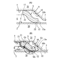
次に、図3に示す他の実施の形態では、他端押圧部16が勾配面(テーパ面)Tをもって構成されている。この勾配面Tはセンタリング機能を発揮する。
さらに具体的に説明すれば、図2(A)は装着未圧縮状態、図2(B)は装着圧縮状態(使用状態)を示し、金属シール5の形状等は図2で述べた通りであるので、説明を省略するが、第1接触平坦面部1を有する第1部材31に於て、勾配面(テーパ面)Tは、第1接触平坦面部1から(鈍角をもって)第2部材32側へ突出状に、連続して形成され、該勾配面Tの外周端縁は、第2接触平坦面部2に接触時に均等に当接するように、第1・第2接触平坦面部1,2と平行な第3平坦面7となっている。
【0024】
図3(A)の装着未圧縮状態から図3(B)の装着圧縮状態に変化するに従って、金属シール5は矢印M1 のように、横断面に於て回転作動し、捩れ弾性変形し、外周端縁15a───他端部22が、押圧部16(勾配面T)によって、押さえられ、流体圧力Pが高圧であっても、浮上りが防止される───第2接触凸部12が第2接触平坦面部2から遊離することが防止される。
【0025】
この図3の実施の形態は、環状の金属シール5の内側(孔部3側)から流体圧力Pが作用する内圧用のシールであり、外周端縁15aを他端部22として、勾配面Tが外周側から押し込む構成である。S字状の金属シール5は、図3(A)から図3(B)のように押圧(圧縮)してゆくに伴って、その外径寸法が若干拡大するように拡径変形するため、第1・第2部材31, 32に対して、センターに設置しないと側壁に拡径変形が妨げられ、円周上シール力(密封力)が不均一となり、特に高圧流体を密封する場合、シール力(密封力)が弱い円周上の一部分から、外部漏洩を生ずるという問題を、図3に示した勾配面Tのセンタリング作用(機能)によって、解決している。
【0026】
次に、図4は別の実施の形態を示す。即ち、金属シール5の外周側を受圧室6とし、外周側から流体圧力Pが作用する、いわゆる外圧用の場合を示す。
既述の実施の形態と同一符号は同様の構成であって、詳細説明は省略するが、相違する点は、この図4の場合、金属シール5の内周端縁14a(他端部22)を押さえ込むための押圧部16を、第2接触平坦面部2(第2部材32)側に形成している点を挙げることができる。つまり、図4は、図2(B)に対応した断面図であり、装着圧縮状態における受圧状態を示している。段付部17を介して、第2接触平坦面部2と平行であって第1接触平坦面部1に接近する方向へ突出状に、押圧面16aが形成され、これによって、他端押圧部16が、第1・第2接触平坦面部1,2とは相違する(第3の)平面上に設けられる。
【0027】
図4に於て、外圧としての流体圧力Pが金属シール5に作用すれば、反時計方向の回転モーメントが金属シール5に作用するが、他端部22(内周端縁14a)は、第3の平面上の押圧面16aにて受持されるので、第1接触凸部11は第1接触平坦面部1から遊離せず、従って、内径方向への流体洩れ(ブローバイ)が防止できる。
なお、図示省略したが、図4に示した押圧部16を、図3に示したような勾配面(テーパ面)Tをもって構成し、金属シール5をその内周端縁14a側からセンタリングさせて、第1・第2部材31, 32に対し正規位置に保持させるも望ましい。
【0028】
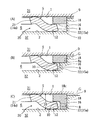
次に、図5と図6は、さらに別の種々の実施の形態を示す要部断面図であって、装着圧縮状態を示している図である。
即ち、図5と図6に示す各実施の形態では、上記第1接触平坦面部1を有する第1部材31、及び、上記第2接触平坦面部2を有する第2部材32とは別部材から成るスペーサ18をもって、上記他端押圧部16を形成した。
【0029】
さらに具体的には、この環状の金属シール5は、環状の内側を受圧室6として、内側から流体圧力が作用する(図2(B)と図3(B)と同様に流体圧力Pが作用するが圧力Pを示す矢印を図示省略した)。つまり内圧用シールである。そして、第2接触凸部12よりも外径側の外周端縁15aから成る他端部22を、スペーサ18の他端押圧部16に対応させて該スペーサ18を第2部材32側に固定する。
【0030】
このように第2部材32側にスペーサ18を固定して、他端押圧部16を第2部材32側に常に配設したことによって、図5,図6のように装着圧縮状態で金属シール5の他端部22が押さえられて、第2接触凸部12が第2接触平坦面部2から高い流体圧力が作用時にも遊離せず、しかも、(図示省略したが)第1部材31が上方へ移動して第2部材32から離れた状態───装着非圧縮状態───に於て、金属シール5の外周端縁15aを、スペーサ18の押圧部16が軽く押圧し、乃至、微小間隙を介して対面して、金属シール5が第2部材32から分離(落下)しないように、保持する。
【0031】
言い換えると、図5と図6のいずれの実施の形態に於ても、スペーサ18は金属シール5を、装着非圧縮状態に於て、第2部材32側に保持し、図10(B)にて述べたような従来の問題を防止できる。つまり、第1・第2平坦面部1,2が鉛直状態や傾斜状態として、(一般的に蓋部材に相当する)第1部材1が、(一般的にケーシング等に相当する)第2部材2から、遊離した状態───開放状態───に於ても、金属シール5が第2部材2から落下せず、金属シール5の取付け時や取外しの際の落下(脱落)問題を有効に防止できる。
【0032】
図5(A)に於ては、スペーサ18は横断面矩形状であって、第2部材32の第2接触平坦面部2から段付面(内側面)8をもって第3平面9が突出状に形成され、この段付面(内側面)8の上方開口端に、スペーサ18が嵌着状に固定され、このスペーサ18の下面と、第2接触平坦面部2との間に、他端部22(外周端縁15a)が差込状とし保持される(内径方向へ開口状の)凹周溝10が形成されている。スペーサ18の外周面と、段付面8とは、はめ合い、圧入又は接着にて固定され、あるいは、(図示省略の)ネジ等の固着手段にて、固定されており、スペーサ18は金属等の剛性の高い硬質材質とする。なお、はめ合いの公差でスペーサ18の外周面を段付面8に対して、多少緩くする場合もありえる(この場合も固定と呼ぶこととする)。
【0033】
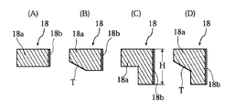
また、図7(A)に示すように、スペーサ18を金属等の剛性の高い硬質材質の本体18aと、段付面8に挿入される本体18aの外周面に被覆されたゴムや樹脂等の弾性層18bとを、もって構成し、スペーサ18と、第2部材32の段付面8との、嵌合公差を吸収するも好ましい。
【0034】
次に、図5(B)に於ては、スペーサ18の形状や構成は、図5(A)と同様であるが、相違する点は、第2部材32の段付面8に、その開口端角部に矩形状切欠部8aを形成し、この切欠部8aに、スペーサ18を嵌着して、僅かに浅い凹周溝10を形成し、また、第1部材31の第1接触平坦面部1がスペーサ18を下方へ強く押圧しても、切欠部8aの底面にて支持し、スペーサ18の第2部材32への固定強度を高めている。なお、第2部材32の第3平面9と、第1接触平坦面部1との間に微小ギャップGを形成し、閉状態(圧縮状態)で、第1接触平坦面部1を、スペーサ18の上面にて受けている場合を、図5(B)に示す。このギャップGを、前述の図5(A)に於ても生ずるように、第1部材31と第2部材32の相互開閉位置関係を設定するも、自由である。
【0035】
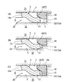
次に、図5(C)に於ては、スペーサ18の形状を、倒立L字型とし、第2部材32の第2接触平坦面部2に下端面が当接するまで(深く)嵌着し、かつ、前記微小ギャップGを生ずるように、スペーサ18の上面18cを、第3平面9よりも僅かに上方へ突出状として、嵌着している。
言い換えれば、第2部材32に於て、第2接触平坦面部2と段付面8によって形成されたシール用凹所20の深さ寸法よりも僅かに大きい高さ(厚さ)寸法Hを有するスペーサ18を、この凹所20に嵌着する構成であり、金属シール5の潰し量、押さえ位置が高精度(寸法精度)をもって、設定できる。特に、金属シール5の他端部22(外周端縁15a)が差込まれて、保持される、凹周溝10の寸法精度が高いという利点もある。なお、所望により、微小ギャップGを無くして(零として)も良い。
【0036】
この図5(C)では、第2部材32の段付面8に十分広い嵌合面積をもってスペーサ18が嵌着(固定)されるので、スペーサ18が常に安定姿勢を保つことができるという利点がある。
【0037】
次に、図6(A)(B)(C)は、各々異なる実施の形態であるが、共通する点は、スペーサ18が勾配面Tを有する点にある。
図6(A)は図5(A)を、図6(B)は図5(B)を、図6(C)は図5(C)を、各々変形した横断面形状であり、勾配面Tを押圧部16に形成した以外の構成は、図5に於て、既に説明したので、ここでは説明を省略する(同一符号は同様の構成である)。なお、図7(B)のスペーサ18は図6(B)に適用可能なものの一例を示し、図7(D)のスペーサ18は図6(C)に適用可能なものの一例である。
【0038】
なお、図5と図6では、内圧用の場合を示したが、これを外圧用に用いる場合には、金属シール5の内周端縁14aと当接するように、図4の押圧部16の位置に───つまり横断面に於て 180°点対称形に───スペーサ18を配設すれば良い。
図6(A)(B)(C)のように勾配面Tを有するスペーサ18を用いることで、金属シール5のセンタリングが行われて、正確な(正規の)位置に金属シール5が保持できる。
【0039】
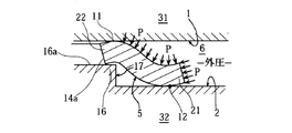
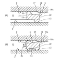
次に、図8はさらに別の実施の形態を示し、図8(A)は装着未圧縮状態を示し、図8(B)は装着圧縮状態かつ受圧状態を示す横断面図である。
図8に示すように、金属シール5の横断面形状は、中間基部13が横断面略矩形であって、第1接触凸部11・第2接触凸部12が、横断面略半円形(又は略半楕円形)である。第1接触凸部11は内径寄りに配設され、第2接触凸部12は外径寄りに配設され、相互に内外径方向に異なる位置である。
【0040】
そして、図8(A)の装着未圧縮状態から、第1・第2接触平坦面部1,2を相互に接近させてゆけば、装着圧縮状態となって、中間基部13を中心に回転する反時計廻りの捩れ弾性変形を生じ、かつ、(図2と同様に形成された)押圧部16の押圧面16aが中間基部13の外周端縁15a側の角部に当接して押圧する。
【0041】
押圧部16は、段付部17をもって第1接触平坦面部1よりも下方へ突出した別の平面上に存在する。図8(B)に於て、内圧として流体圧力Pが作用した受圧状態で、この流体圧力Pにより、他端部22(外周端縁15a)が押圧部16(の押圧面16a)に接触する点を中心とする回転モーメントの総和は、時計廻りとなり、第2接触凸部12は第2接触平坦面部2に常に圧接状に押圧されて、この部位からの流体洩れは防止できる。
【0042】
本発明は上述のような構成であり、例えば内圧が作用する場合、流体圧力Pが高くなると外周寄りの第2接触凸部12が第2接触平坦面部2から浮いてしまう浮上り現象を、押圧部16によって、有効に防止して、高圧でも密封性(シール性)を維持することができる。また、外圧が作用する場合(図4参照)、流体圧力Pが高くなると、内周寄りの第1接触凸部11が第1接触平坦面部1から浮いてしまう浮上り現象を、突起部7によって、有効に防止し、高圧下での密封性(シール性)を確保する。しかも、無理矢理に第1・第2接触平坦面部1,2が相互に接近する方向に強く締付けることなく、低締付力のままにて、高圧の流体圧力Pに対して(高圧環境下で)、密封性(シール性)を巧妙に維持できる。そして、流体圧力が高い環境下に於て、(低締付力のままで、)流体圧力自体を利用して、シール性を高めることを可能とした構成である。このように本願発明は、高圧時のシール性を向上させるために、特別に複雑な構造や部品を必要としない密封構造体である。
【0043】
また、本発明によれば、大きな潰し量をもって金属シール5を押圧せずに、高圧下で密封できる構成であるので、金属シール5の塑性変形が生じないか、生じても僅かであって、常時、弾性反発力によって優れた密封性(シール性)を維持できる。
また、押圧部16を勾配面(テーパ面)Tとすれば、金属シール5をセンタリングして、正規中心位置に保持できる。この種の捩れ弾性変形しつつ圧縮される金属シール5は、押圧時に径方向に若干拡径するため、正規中心位置(センター)に保持しないと、シール用凹所20の内周面に拡径変形が阻止され、円周位置によってシール力にムラを生ずることも考えられ、高圧流体を密封する場合に、シール力の弱い円周の一部から、洩れを生ずるといった問題を生ずるのを、本発明では、前述の勾配面(テーパ面)Tを押圧部16に形成することで、解決している。
【0044】
そして、図5及び図6のように、スペーサ18を用いる場合、スペーサ18は装着圧縮状態で第1部材31の第1接触平坦面部1によって、当接保持されている───押さえ付けられている───ので、流体圧力Pが高圧となっても、スペーサ18は十分に耐えることができて、常に浮上りを防ぎ得る。
そして、図5と図6の各実施の形態のように、スペーサ18を第2部材32へ固定した構造とすれば、図10にて述べた従来の金属シール41の位置ずれ、及び、脱落の問題をも有効に防止できる。
【0045】
さらに補足説明すれば、本発明の特徴の一つは、受圧室6側の一端部21と反対の他端部22を、装着圧縮状態で、押圧部16をもって押さえることで、高圧環境下での高いシール性能を発揮する。このように、他端部22を押圧部16にて押さえ、拘束することによって、金属シール5は、図2(B)又は図3(B)に示した如く、第1接触凸部11と第2接触凸部12と他端部22の3点Q1 ,Q2 ,Q3 にて押さえ込まれ、安定した弾発的接触状態を保持することで、安定して高いシール性(密封性)を維持できる。
【0046】
第3の点Q3 は、第1の点Q1 と異なる高さに配設され、第1部材31が金属シール5を押圧する高さ(上下)位置が異なるので、従来の図9(B)の如く必要以上に潰す必要がなく、金属シール5の過大な塑性変形を防ぎ、相手部材───第1・第2接触平坦面部1,2───の圧潰やクリープ変形等を防止して、長期間、優れたシール性能を維持できる。また、押圧部16の押圧面16aの第1接触平坦面部1からの高さ寸法H16を適正に設定することで、第1接触凸部11と第1接触平坦面部1との間に過大な圧縮面圧が作用することを防止することも容易にでき、締付力を最小必要限度とすることができる。
【0047】
また、図1〜図6に示すようなS字状の金属シール5を用いれば、図2(B)と図3(B)に示した点Q2 と点Q3 での接触位置で金属シール5は弾性変形して、温度変動や圧力サイクルによって、一般にフランジ(蓋部材)から成る第1部材31が変位しても、良好に追従して、シール性を維持できる。
また、勾配面(テーパ面)Tを有する場合に、金属シール5のセンタリングの作用・効果は既に述べたが、このセンタリングされることに伴って、金属シール5の他端部22は均一に押さえられ、高圧の流体圧力Pが作用したとしても安定したシール性(密封性)を保つ。かつ、押圧部16の寸法を厳密にする必要がなくなって、各部材の作製が容易となる。
なお、金属シール5の他端部22を押さえる際に、その押圧力を最適値に設定するためには、ねじ込みによるトルク管理にて第1・第2部材31, 32を相互に締付けるのが望ましい。
【0048】
【発明の効果】
本発明は、上述の構成により次のような著大な効果を奏する。
(請求項1,2,3によれば、)低締付力で使用でき、取付部材(フランジ等)の肉厚が薄く強度が低いものにも適用できる。しかも、流体圧力Pが高い使用条件下で、この低締付力のままで、金属シール5の浮上りを有効に防止でき、流体洩れを防止できる。
また、装着圧縮状態にて全体が捩れ弾性変形を生ずることにより、弾性的復元量(弾性変形領域)が大きく、広いセット高さ───第1・第2接触平坦面部1,2相互間隔寸法───に対応でき、低圧から高圧の広い範囲で、取付部材の寸法公差が大きくとも、常に安定して高いシール性(密封性)を発揮する。
【0049】
装着圧縮状態における受圧状態及び非受圧状態のいずれにあっても、低締付力をそのまま維持できる。即ち、フランジ等の取付部材に余分な締付荷重を必要とせず、構造の簡素化を図り、かつ、金属シール5との大きな接触面圧部位が無いので、第1・第2接触平坦面部1,2の接触面に損傷を生じさせず、長期間にわたって優れたシール性(密封性)を発揮する。
【0050】
(請求項4によれば、)他端部22を適正に押付ける力を付与するために高精度の高さ寸法に、加工し易い。
【図面の簡単な説明】
【図1】 本発明の実施の一形態を示す断面正面図である。
【図2】 作用説明を兼ねた要部拡大断面図であって、(A)は装着未圧縮状態を示し、(B)は装着圧縮状態を示す。
【図3】 作用説明を兼ねた要部拡大断面図であって、(A)は装着未圧縮状態を示し、(B)は装着圧縮状態に於ける受圧状態を示す。
【図4】 他の実施の形態を示す要部拡大断面図であって、装着圧縮かつ受圧状態を示す。
【図5】 各々別の実施の形態を示す要部拡大断面図である。
【図6】 各々別の実施の形態を示す要部拡大断面図である。
【図7】 スペーサの変形例を説明する横断面図である。
【図8】 別の実施の形態を示す、作用説明を兼ねた要部拡大断面図であって、(A)は装着未圧縮状態を示し、(B)は装着圧縮状態に於ける受圧状態を示す。
【図9】 従来例の問題点を説明するための要部拡大断面図である。
【図10】 従来例の別の問題点を説明するための要部拡大断面図である。
【符号の説明】
1 第1接触平坦面部
2 第2接触平坦面部
5 金属シール
6 受圧室
11 第1接触凸部
12 第2接触凸部
13 中間基部
14a 内周端縁
15a 外周端縁
16 押圧部
16b 突出部
18 スペーサ
21 一端部
22 他端部
31 第1部材
32 第2部材
P 流体圧力
Q,Q 3 点
T 勾配面(テーパ面)[0001]
BACKGROUND OF THE INVENTION
The present invention relates to a sealing structure using a metal seal.
[0002]
[Prior art]
Conventionally, a rubber O-ring has been widely used as a sealing material, but may not be used in high temperature, low temperature, rubber corrosive gas environments, and the like. Therefore, metal seals such as the following (1) to (4) have been conventionally used. That is, (1) Metal O-ring, (2) Metal C-ring, (3) Spring loaded C-ring, (4) Regent seal, etc. are used.
[0003]
However, each metal seal has the following problems.
(1) Metal O-ring
It is the most common and proven metal seal and can provide stable sealing performance, but it has drawbacks such as a large clamping force and a small restoration amount of about 0.05 mm.
(2) Metal C-ring
The tightening force is smaller than that of the metal O-ring and the amount of restoration is relatively large, which is about 0.05 mm to 0.15 mm. However, depending on the application (use conditions), the value of the tightening force is still large and the amount of restoration is insufficient.
(3) Spring loaded C-ring
The amount of restoration is as large as 0.1 to 0.15 mm. However, the restoration amount is insufficient depending on the application (use conditions). Further, since the coil spring is enclosed in the C-ring main body so as to wrap, there are disadvantages that the production is complicated and the structure is complicated, the tightening force is large, and the cost is high.
(4) Regent seal
Compared to other metal seals, the tightening force is small, and the amount of restoration is as large as 0.1 to 0.2 mm. However, since it is a cutting process, production is troublesome and very expensive.
[0004]
In short, there is no conventional metal seal that can satisfy all the conditions (requests) that it is easy to manufacture, has a small clamping force, has a large amount of elastic restoration, and is inexpensive.
[0005]
In view of this, the inventors of the present invention have proposed in Japanese Patent Application No. 2002-199363 a gently-
[0006]
Thus, the tightening force (arrow F1 , F2 (See Fig. 9 (A)). However, the
That is, as shown by an arrow Z in FIG. 9A, a high fluid pressure P ... acts on the
As a method for solving such a problem, an invention has been proposed in which a member for pressing the entire back surface of the metal seal is added (see, for example, Patent Document 1).
[0007]
[Patent Document 1]
JP 2001-324021 A
[0008]
[Problems to be solved by the invention]
However, pressing the entire back surface of the metal seal is excellent in that it can withstand extremely high pressure as a cylinder head of an engine of an internal combustion engine, but the small fastening force F described above is used.1 , F2 The maximum merit that it can be used will be lost. In other words, the metal seal as in
[0009]
Further, as shown in FIG. 9B, the first and second
[0010]
That is, excessive torsional elastic deformation is caused in the metal seal 41 (giving an excessive amount of crushing), the
[0011]
Further, the usage form of this type of
When the
[0012]
The present invention provides a sealed structure that has a small tightening force and a high resilience, and thus the tightening structure is simplified, the flange portion and the like may be thin, and the contact surface with the metal seal is not damaged. The purpose is to provide. In particular, another object is to provide a sealing structure that exhibits excellent sealing performance (sealing performance) even when high fluid pressure is applied. Another object of the present invention is to provide a sealing structure that does not fall off or is not displaced when the metal seal is assembled or removed (the center easily matches).
[0013]
[Means for Solving the Problems]
The present invention includes a first contact flat surface portion and a second contact flat surface portion that are parallel to each other, and a whole metal seal that is interposed between the first and second contact flat surface portions. In the structure, the metal seal has an S-shaped section that is gently curved with the same wall thickness, and includes an intermediate base, a first contact convex portion that contacts the first contact flat surface portion, and the second contact. A second contact convex portion that contacts the flat contact surface portion, and the first contact convex portion and the second contact convex portion are arranged differently toward the inner diameter side and the outer diameter side, and in a mounted compression state. The metal seal causes torsional elastic deformation that rotates about the intermediate base, and the other end pressing portion that holds the other end opposite to the one end on the pressure receiving chamber side in the mounted compression state is the first contact. The metal is provided on a plane different from the flat surface portion and the second contact flat surface portion, and further, the metal is entirely annular Lumpur is an inner pressure of the fluid pressure acts from inside of the annular,The pressure receiving chamber is disposed inside the annular shape,The other end portion formed by the outer peripheral edge on the outer diameter side than the second contact convex portion is pressed in the attached compressed state.the aboveThe other end pressing portion is configured with a protruding portion formed on the first contact flat surface portion side, and the metal seal is configured so that the corner portion of the outer peripheral edge is a point in a cross section in a mounted compression state, and the protruding portion It was configured to be held in contact with.
[0014]
In addition, the sealing structure includes a first contact flat surface portion and a second contact flat surface portion parallel to each other, and an entire metal seal interposed between the first and second contact flat surface portions. In this case, the metal seal has an S-shaped section that is gently curved with the same thickness, and has an intermediate base, a first contact convex portion that contacts the first contact flat surface portion, and the second contact flatness. A second contact convex portion that contacts the surface portion, and the first contact convex portion and the second contact convex portion are disposed differently toward the inner diameter side and the outer diameter side, and in the mounted compression state, The metal seal causes torsional elastic deformation that rotates about the intermediate base, and the other end pressing portion that holds the other end opposite to the one end on the pressure receiving chamber side in the mounted compression state is the first contact flat surface portion. And the second contact flat surface portion is provided on a plane different from the second contact flat surface portion. Is a for external pressure fluid pressure is applied from the outside of the annular,The pressure receiving chamber is disposed outside the annular shape,The other end portion constituted by the inner peripheral end edge on the inner diameter side than the first contact convex portion is pressed in a compression state.the aboveThe other end pressing portion is constituted by a protruding portion formed on the second contact flat surface portion side, and the metal seal has the protruding portion with a corner portion of the inner peripheral edge as a point in a cross section in a mounted compression state. It was configured to be held in contact with the part.
[0015]
In addition, the sealing structure includes a first contact flat surface portion and a second contact flat surface portion parallel to each other, and an entire metal seal interposed between the first and second contact flat surface portions. The metal seal has an intermediate base portion having a substantially rectangular cross section, a first contact convex portion having a substantially semicircular cross section that contacts the first contact flat surface portion, and a cross section that contacts the second contact flat surface portion. A substantially semicircular second contact convex portion, and the first contact convex portion and the second contact convex portion are arranged differently toward the inner diameter side and the outer diameter side, and in the mounted compression state, The metal seal causes torsional elastic deformation that rotates about the intermediate base, and the other end pressing portion that holds the other end opposite to the one end on the pressure receiving chamber side in the mounted compression state is the first contact flat surface portion. And the second contact flat surface portion is provided on a plane different from that of the second contact flat surface portion. From the inside of the annular be for pressure fluid pressure acts,The pressure receiving chamber is disposed inside the annular shape,The other end portion formed by the outer peripheral edge on the outer diameter side than the second contact convex portion is pressed in the attached compressed state.the aboveThe other end pressing portion is constituted by a protruding portion formed on the first contact flat surface portion side, and the metal seal has a corner portion on the outer peripheral edge side of the intermediate base portion as a point in a cross section in a mounted compression state. , And configured to be held in contact with the protruding portion.
Moreover, the said other end pressing part was formed with the spacer which consists of a 1st member which has the said 1st contact flat surface part, and the 2nd member which has the said 2nd contact flat surface part.
[0016]
DETAILED DESCRIPTION OF THE INVENTION
Hereinafter, the present invention will be described in detail based on the illustrated embodiment.
FIG. 1 is an overall cross-sectional front view of a
[0017]
This metal seal (metal seal) 5 is made of stainless steel, spring steel, or other metal, and is preferably formed from a thin plate material by press working (plastic working) from the viewpoint of ease of manufacture and cost. It can also be produced by machining such as grinding. In addition, the
[0018]
The
Further, the
[0019]
Specifically, the inner
As described above, the
[0020]
Then, as the mounting uncompressed state shown in FIG. 2 (A) changes to the mounting / compressed state shown in FIG. 2 (B), the
[0021]
In summary, in other words, the first contact
[0022]
Since the
[0023]
Next, in another embodiment shown in FIG. 3, the other
More specifically, FIG. 2A shows the uncompressed state, FIG. 2B shows the attached compressed state (use state), and the shape and the like of the
[0024]
As the mounting uncompressed state in FIG. 3A changes to the mounting compressed state in FIG.1 As shown in the figure, it rotates in the cross section, undergoes torsional elastic deformation, the outer
[0025]
The embodiment of FIG. 3 is an internal pressure seal in which fluid pressure P acts from the inside (
[0026]
Next, FIG. 4 shows another embodiment. That is, a case of so-called external pressure in which the outer peripheral side of the
The same reference numerals as those of the above-described embodiment are the same in configuration, and detailed description is omitted, but the difference is that in the case of FIG. 4, the inner
[0027]
In FIG. 4, if the fluid pressure P as an external pressure acts on the
Although not shown, the
[0028]
Next, FIG. 5 and FIG. 6 are main part sectional views showing still other various embodiments, and are views showing a mounted compression state.
That is, in each embodiment shown in FIGS. 5 and 6, the
[0029]
More specifically, the
[0030]
In this way, the
[0031]
In other words, in either of the embodiments shown in FIGS. 5 and 6, the
[0032]
In FIG. 5A, the
[0033]
Further, as shown in FIG. 7A, the
[0034]
Next, in FIG. 5B, the shape and configuration of the
[0035]
Next, in FIG. 5C, the shape of the
In other words, the
[0036]
In FIG. 5C, since the
[0037]
Next, FIGS. 6A, 6B, and 6C are different embodiments, but the common point is that the
6 (A) is a modified cross-sectional shape of FIG. 5 (A), FIG. 6 (B) is FIG. 5 (B), and FIG. 6 (C) is FIG. 5 (C). Since the configuration other than the formation of T in the
[0038]
5 and 6 show the case for the internal pressure, but when this is used for the external pressure, the
By using the
[0039]
Next, FIG. 8 shows still another embodiment, FIG. 8 (A) shows an uncompressed state of attachment, and FIG. 8 (B) is a cross-sectional view showing an attached compressed state and a pressure receiving state.
As shown in FIG. 8, the cross-sectional shape of the
[0040]
Then, if the first and second contact
[0041]
The
[0042]
BookThe invention is configured as described above. For example, when the internal pressure is applied, when the fluid pressure P is increased, the second contact
[0043]
In addition, according to the present invention, the
If the
[0044]
As shown in FIGS. 5 and 6, when the
5 and 6, if the
[0045]
In addition, one of the features of the present invention is that the
[0046]
Third point QThree Is the first point Q1 Since the height (vertical) position at which the
[0047]
Moreover, if the S-shaped
In addition, when the sloped surface (tapered surface) T is provided, the operation and effect of the centering of the
In order to set the pressing force to the optimum value when the
[0048]
【The invention's effect】
The present invention has the following remarkable effects by the above-described configuration.
(
In addition, the entire structure undergoes torsional elastic deformation in the attached compression state, so that the amount of elastic recovery (elastic deformation region) is large and the set height is wide. ─── can be applied, and in a wide range from low pressure to high pressure, even if the dimensional tolerance of the mounting member is large, it always exhibits a stable and high sealing performance.
[0049]
The low tightening force can be maintained as it is in either the pressure receiving state or the non-pressure receiving state in the attached compression state. That is, no extra tightening load is required on the mounting member such as a flange, the structure is simplified, and there is no large contact surface pressure portion with the
[0050]
(According to claim 4)Easy to work with high-precision height to give the force to press the
[Brief description of the drawings]
FIG. 1 is a cross-sectional front view showing an embodiment of the present invention.
FIGS. 2A and 2B are enlarged cross-sectional views of a main part that also serves to explain the operation, in which FIG. 2A shows an uncompressed state of attachment, and FIG.
FIGS. 3A and 3B are enlarged cross-sectional views of main parts that also serve for explanation of operation, in which FIG. 3A shows a non-compressed state of attachment, and FIG.
FIG. 4 is an enlarged cross-sectional view of a main part showing another embodiment, showing a compression state and a pressure receiving state.
FIG. 5 is an enlarged cross-sectional view of a main part showing another embodiment.
FIG. 6 is an enlarged cross-sectional view of a main part showing another embodiment.
FIG. 7 is a cross-sectional view illustrating a modified example of a spacer.
FIGS. 8A and 8B are enlarged cross-sectional views showing a main part and an explanation of operation according to another embodiment, in which FIG. 8A shows an uncompressed state of attachment and FIG. 8B shows a pressure receiving state in the attached compression state. Show.
FIG. 9 is an enlarged cross-sectional view of a main part for explaining problems of a conventional example.
FIG. 10 is an enlarged cross-sectional view of a main part for explaining another problem of the conventional example.
[Explanation of symbols]
1 1st contact flat surface part
2 Second contact flat surface
5 Metal seal
6 Pressure receiving chamber
11 First contact protrusion
12 Second contact protrusion
13 Intermediate base
14a Inner edge
15a Outer edge
16 Pressing part
16b Protrusion
18 Spacer
21 One end
22 other end
31 First member
32 Second part
P Fluid pressure
Q, Q Three point
T Inclined surface (tapered surface)
Claims (4)
Priority Applications (3)
| Application Number | Priority Date | Filing Date | Title |
|---|---|---|---|
| JP2003103577A JP4331502B2 (en) | 2003-04-08 | 2003-04-08 | Sealed structure |
| US10/620,372 US7004479B2 (en) | 2002-07-19 | 2003-07-17 | Metal seal and attachment method for the same and tight-seal construction |
| US11/179,485 US7083171B2 (en) | 2002-07-19 | 2005-07-13 | Metal seal and attachment method for the same and tight-seal construction |
Applications Claiming Priority (1)
| Application Number | Priority Date | Filing Date | Title |
|---|---|---|---|
| JP2003103577A JP4331502B2 (en) | 2003-04-08 | 2003-04-08 | Sealed structure |
Publications (2)
| Publication Number | Publication Date |
|---|---|
| JP2004308802A JP2004308802A (en) | 2004-11-04 |
| JP4331502B2 true JP4331502B2 (en) | 2009-09-16 |
Family
ID=33466630
Family Applications (1)
| Application Number | Title | Priority Date | Filing Date |
|---|---|---|---|
| JP2003103577A Expired - Lifetime JP4331502B2 (en) | 2002-07-19 | 2003-04-08 | Sealed structure |
Country Status (1)
| Country | Link |
|---|---|
| JP (1) | JP4331502B2 (en) |
Families Citing this family (1)
| Publication number | Priority date | Publication date | Assignee | Title |
|---|---|---|---|---|
| FR2891606B1 (en) * | 2005-10-05 | 2009-03-06 | Snecma Sa | FLANGED CONNECTION DEVICE. |
Family Cites Families (5)
| Publication number | Priority date | Publication date | Assignee | Title |
|---|---|---|---|---|
| FR1540946A (en) * | 1967-04-13 | 1968-10-04 | Deformable Metal Seal Pipe Fitting | |
| JPS49145008U (en) * | 1973-04-16 | 1974-12-13 | ||
| JP2000027998A (en) * | 1998-07-10 | 2000-01-25 | Nok Corp | Sealing device |
| JP3646770B2 (en) * | 1998-07-27 | 2005-05-11 | Nok株式会社 | Gasket for fuel cell |
| JP2001324021A (en) * | 2000-05-12 | 2001-11-22 | Toyota Motor Corp | Sealing structure and combustion gas seal structure of in-cylinder fuel injection valve and in-cylinder fuel injection valve |
-
2003
- 2003-04-08 JP JP2003103577A patent/JP4331502B2/en not_active Expired - Lifetime
Also Published As
| Publication number | Publication date |
|---|---|
| JP2004308802A (en) | 2004-11-04 |
Similar Documents
| Publication | Publication Date | Title |
|---|---|---|
| US6769697B1 (en) | Gasket | |
| JP5252878B2 (en) | Rotating shaft seal | |
| US10612660B2 (en) | Gasket | |
| CN1884874B (en) | Compressible gasket | |
| JPS61160667A (en) | Clamping mechanism of diaphragm plate | |
| JP2011094667A (en) | Gasket and sealing structure | |
| JP4091373B2 (en) | Metal seal | |
| JP3419447B2 (en) | Head gasket | |
| US20020050684A1 (en) | Brush seal device | |
| JP4331502B2 (en) | Sealed structure | |
| JP4099648B2 (en) | Gasket for fuel cell | |
| JP4538238B2 (en) | gasket | |
| JP2000230638A (en) | Metal gasket with bore | |
| WO2002031354A1 (en) | Combustion gas seal for injector | |
| JP4597912B2 (en) | Chemical valve | |
| JP4128802B2 (en) | Plasma resistant seal | |
| JP2004340315A (en) | Metal seal | |
| JP4199013B2 (en) | Sealed structure | |
| JPH0241397Y2 (en) | ||
| JP2000283296A (en) | Packing | |
| JP4260496B2 (en) | Metal seal | |
| JP2002349711A (en) | Gasket | |
| CN213711868U (en) | Sealing device and sealing structure | |
| JP2003336601A (en) | Accumulator | |
| TW202421944A (en) | Annular metal seal, installation structure of annular metal seal, and installation method of annular metal seal |
Legal Events
| Date | Code | Title | Description |
|---|---|---|---|
| A621 | Written request for application examination |
Free format text: JAPANESE INTERMEDIATE CODE: A621 Effective date: 20060228 |
|
| A977 | Report on retrieval |
Free format text: JAPANESE INTERMEDIATE CODE: A971007 Effective date: 20081023 |
|
| A131 | Notification of reasons for refusal |
Free format text: JAPANESE INTERMEDIATE CODE: A131 Effective date: 20081104 |
|
| A521 | Request for written amendment filed |
Free format text: JAPANESE INTERMEDIATE CODE: A523 Effective date: 20081222 |
|
| A131 | Notification of reasons for refusal |
Free format text: JAPANESE INTERMEDIATE CODE: A131 Effective date: 20090310 |
|
| A521 | Request for written amendment filed |
Free format text: JAPANESE INTERMEDIATE CODE: A523 Effective date: 20090423 |
|
| TRDD | Decision of grant or rejection written | ||
| A01 | Written decision to grant a patent or to grant a registration (utility model) |
Free format text: JAPANESE INTERMEDIATE CODE: A01 Effective date: 20090609 |
|
| A01 | Written decision to grant a patent or to grant a registration (utility model) |
Free format text: JAPANESE INTERMEDIATE CODE: A01 |
|
| A61 | First payment of annual fees (during grant procedure) |
Free format text: JAPANESE INTERMEDIATE CODE: A61 Effective date: 20090618 |
|
| R150 | Certificate of patent or registration of utility model |
Free format text: JAPANESE INTERMEDIATE CODE: R150 Ref document number: 4331502 Country of ref document: JP Free format text: JAPANESE INTERMEDIATE CODE: R150 |
|
| FPAY | Renewal fee payment (event date is renewal date of database) |
Free format text: PAYMENT UNTIL: 20120626 Year of fee payment: 3 |
|
| FPAY | Renewal fee payment (event date is renewal date of database) |
Free format text: PAYMENT UNTIL: 20120626 Year of fee payment: 3 |
|
| FPAY | Renewal fee payment (event date is renewal date of database) |
Free format text: PAYMENT UNTIL: 20130626 Year of fee payment: 4 |
|
| FPAY | Renewal fee payment (event date is renewal date of database) |
Free format text: PAYMENT UNTIL: 20140626 Year of fee payment: 5 |
|
| R250 | Receipt of annual fees |
Free format text: JAPANESE INTERMEDIATE CODE: R250 |
|
| R250 | Receipt of annual fees |
Free format text: JAPANESE INTERMEDIATE CODE: R250 |
|
| R250 | Receipt of annual fees |
Free format text: JAPANESE INTERMEDIATE CODE: R250 |
|
| EXPY | Cancellation because of completion of term |