JP4331071B2 - Cooker - Google Patents
Cooker Download PDFInfo
- Publication number
- JP4331071B2 JP4331071B2 JP2004248371A JP2004248371A JP4331071B2 JP 4331071 B2 JP4331071 B2 JP 4331071B2 JP 2004248371 A JP2004248371 A JP 2004248371A JP 2004248371 A JP2004248371 A JP 2004248371A JP 4331071 B2 JP4331071 B2 JP 4331071B2
- Authority
- JP
- Japan
- Prior art keywords
- heating
- coil
- cooked
- heating element
- induction heating
- Prior art date
- Legal status (The legal status is an assumption and is not a legal conclusion. Google has not performed a legal analysis and makes no representation as to the accuracy of the status listed.)
- Expired - Fee Related
Links
- 238000010438 heat treatment Methods 0.000 claims description 189
- 230000006698 induction Effects 0.000 claims description 63
- 239000004020 conductor Substances 0.000 claims description 61
- 239000000463 material Substances 0.000 claims description 52
- 238000010411 cooking Methods 0.000 claims description 43
- 239000007769 metal material Substances 0.000 claims description 21
- 238000001514 detection method Methods 0.000 claims description 12
- 229910052755 nonmetal Inorganic materials 0.000 claims description 6
- 239000000696 magnetic material Substances 0.000 claims description 5
- 229910052782 aluminium Inorganic materials 0.000 description 14
- XAGFODPZIPBFFR-UHFFFAOYSA-N aluminium Chemical compound [Al] XAGFODPZIPBFFR-UHFFFAOYSA-N 0.000 description 14
- 230000004907 flux Effects 0.000 description 12
- XEEYBQQBJWHFJM-UHFFFAOYSA-N Iron Chemical compound [Fe] XEEYBQQBJWHFJM-UHFFFAOYSA-N 0.000 description 10
- RYGMFSIKBFXOCR-UHFFFAOYSA-N Copper Chemical compound [Cu] RYGMFSIKBFXOCR-UHFFFAOYSA-N 0.000 description 6
- 229910052802 copper Inorganic materials 0.000 description 6
- 239000010949 copper Substances 0.000 description 6
- 229910001220 stainless steel Inorganic materials 0.000 description 6
- 239000010935 stainless steel Substances 0.000 description 6
- 239000004927 clay Substances 0.000 description 5
- 230000001965 increasing effect Effects 0.000 description 5
- 229910052742 iron Inorganic materials 0.000 description 5
- 239000003990 capacitor Substances 0.000 description 4
- 238000009434 installation Methods 0.000 description 4
- 238000000034 method Methods 0.000 description 4
- 230000002093 peripheral effect Effects 0.000 description 4
- 238000010586 diagram Methods 0.000 description 3
- 230000003247 decreasing effect Effects 0.000 description 2
- 230000002500 effect on skin Effects 0.000 description 2
- 230000035699 permeability Effects 0.000 description 2
- 230000008569 process Effects 0.000 description 2
- 230000015556 catabolic process Effects 0.000 description 1
- 230000008859 change Effects 0.000 description 1
- 239000012141 concentrate Substances 0.000 description 1
- 230000000694 effects Effects 0.000 description 1
- 238000005516 engineering process Methods 0.000 description 1
- 230000001939 inductive effect Effects 0.000 description 1
- 239000011810 insulating material Substances 0.000 description 1
- 238000009413 insulation Methods 0.000 description 1
- 239000012212 insulator Substances 0.000 description 1
- 238000012986 modification Methods 0.000 description 1
- 230000004048 modification Effects 0.000 description 1
- 150000002843 nonmetals Chemical class 0.000 description 1
- 229910000859 α-Fe Inorganic materials 0.000 description 1
Images


Classifications
-
- H—ELECTRICITY
- H05—ELECTRIC TECHNIQUES NOT OTHERWISE PROVIDED FOR
- H05B—ELECTRIC HEATING; ELECTRIC LIGHT SOURCES NOT OTHERWISE PROVIDED FOR; CIRCUIT ARRANGEMENTS FOR ELECTRIC LIGHT SOURCES, IN GENERAL
- H05B6/00—Heating by electric, magnetic or electromagnetic fields
- H05B6/02—Induction heating
- H05B6/10—Induction heating apparatus, other than furnaces, for specific applications
- H05B6/12—Cooking devices
-
- A—HUMAN NECESSITIES
- A47—FURNITURE; DOMESTIC ARTICLES OR APPLIANCES; COFFEE MILLS; SPICE MILLS; SUCTION CLEANERS IN GENERAL
- A47J—KITCHEN EQUIPMENT; COFFEE MILLS; SPICE MILLS; APPARATUS FOR MAKING BEVERAGES
- A47J36/00—Parts, details or accessories of cooking-vessels
- A47J36/02—Selection of specific materials, e.g. heavy bottoms with copper inlay or with insulating inlay
-
- H—ELECTRICITY
- H05—ELECTRIC TECHNIQUES NOT OTHERWISE PROVIDED FOR
- H05B—ELECTRIC HEATING; ELECTRIC LIGHT SOURCES NOT OTHERWISE PROVIDED FOR; CIRCUIT ARRANGEMENTS FOR ELECTRIC LIGHT SOURCES, IN GENERAL
- H05B6/00—Heating by electric, magnetic or electromagnetic fields
- H05B6/02—Induction heating
- H05B6/06—Control, e.g. of temperature, of power
- H05B6/062—Control, e.g. of temperature, of power for cooking plates or the like
- H05B6/065—Control, e.g. of temperature, of power for cooking plates or the like using coordinated control of multiple induction coils
-
- H—ELECTRICITY
- H05—ELECTRIC TECHNIQUES NOT OTHERWISE PROVIDED FOR
- H05B—ELECTRIC HEATING; ELECTRIC LIGHT SOURCES NOT OTHERWISE PROVIDED FOR; CIRCUIT ARRANGEMENTS FOR ELECTRIC LIGHT SOURCES, IN GENERAL
- H05B6/00—Heating by electric, magnetic or electromagnetic fields
- H05B6/02—Induction heating
- H05B6/10—Induction heating apparatus, other than furnaces, for specific applications
- H05B6/12—Cooking devices
- H05B6/1209—Cooking devices induction cooking plates or the like and devices to be used in combination with them
- H05B6/1245—Cooking devices induction cooking plates or the like and devices to be used in combination with them with special coil arrangements
Landscapes
- Physics & Mathematics (AREA)
- Electromagnetism (AREA)
- Engineering & Computer Science (AREA)
- Food Science & Technology (AREA)
- Induction Heating Cooking Devices (AREA)
- Electric Stoves And Ranges (AREA)
- General Induction Heating (AREA)
- Cookers (AREA)
Description
本発明は、調理器本体の上面を構成するトッププレート上に載置される被加熱調理器具を加熱するための加熱手段を備えた加熱調理器に関する。 The present invention relates to a heating cooker provided with a heating means for heating a cooked utensil placed on a top plate that constitutes the upper surface of a cooker body.
誘導加熱調理器においては、アルミ製や銅製の鍋のように低透磁率で電気伝導度が高い材料で構成される被加熱調理器具を如何にして加熱するかが課題となっている。この課題を解決するための従来技術として、特許文献1には、誘導加熱を行う場合に発生する反発力による鍋の浮きや移動を検出し、加熱コイルに供給する電流を制限する構成が開示されている。また、特許文献2には、加熱コイルと鍋との間にアルミ板を挿入し、そのアルミ板を誘導加熱することで鍋を間接的に加熱するようにした構成が開示されている。
しかしながら、特許文献1に開示されている技術では、鍋の重量が軽いため反発力を抑制しにくい場合には電流の供給を大幅に制限することになり、結果として火力が低下し、十分な加熱を行なうことができなくなるという問題がある。
また、特許文献2に開示されている技術では、アルミ板を介して鍋を間接的に加熱するので加熱効率が低下する。即ち、アルミ板は鍋と同様に誘導加熱されるので、その分だけインバータや加熱コイルにおける損失が増加する。特に、アルミには大きな電流が流れることから、加熱コイルの巻き数を3倍程度に増加させたり交流電流の周波数を高めるようにする必要があり、鉄製の鍋などを加熱する場合に比較して損失が大きくなる。その加熱効率は65%程度であり、一般的な誘導加熱調理器の加熱効率85%に比べると非常に悪い。特許文献2の技術について具体数値例を挙げると、入力電力3kW,アルミ鍋を直接加熱する電力を800W,アルミ板による間接加熱の電力を2.2kWとすれば、その35%として770W分だけ効率が低下することになる。
However, in the technique disclosed in
Moreover, in the technique currently disclosed by
本発明は上記事情に鑑みてなされたものであり、その目的は、低透磁率の材料で構成される被加熱調理器具をより効率よく加熱することができる加熱調理器を提供することにある。 This invention is made | formed in view of the said situation, The objective is to provide the heating cooker which can heat the to-be-heated cooking appliance comprised with the material of low magnetic permeability more efficiently.
本発明の加熱調理器は、調理器本体と、
この調理器本体の上面を構成し、被加熱調理器具が載置されるトッププレートと、
誘導加熱コイルと発熱体とで構成され、これらの少なくとも一方によって前記被加熱調理器具を加熱可能に配置される加熱手段と、
前記誘導加熱コイルに高周波電流を供給する高周波電流供給手段と、
前記発熱体に通電を行って発熱させるための通電手段と、
前記高周波電流供給手段と前記通電手段とに夫々供給する電力を制御することで、前記被加熱調理器具に対する加熱を制御する加熱制御手段と、
前記被加熱調理器具の材質を判定する材質判定手段とを備え、
前記加熱制御手段は、前記材質判定手段によって判定された材質が、高抵抗金属材料,低抵抗金属材料,非金属材料の何れであるかに応じて前記被加熱調理器具を前記誘導加熱コイルと前記発熱体とで加熱する割合を制御し、誘導加熱では効率が低下する材質の被加熱調理器具を加熱する場合には前記発熱体による加熱割合を相対的に上昇させることを特徴とする。
The heating cooker of the present invention includes a cooker body,
A top plate that constitutes the upper surface of the cooker body, and on which the cooked utensils are placed,
A heating means that is configured by an induction heating coil and a heating element, and is arranged so as to heat the cooked utensil by at least one of these;
High-frequency current supply means for supplying a high-frequency current to the induction heating coil;
Energization means for energizing the heating element to generate heat;
Heating control means for controlling heating of the cooked utensil by controlling the power supplied to the high-frequency current supply means and the energization means ,
A material determining means for determining the material of the cooked utensil,
The heating control means is configured such that the cooking appliance is heated with the induction heating coil according to whether the material determined by the material determining means is a high resistance metal material, a low resistance metal material, or a non-metal material. to control the rate of heating by the heating element, the induction heating when heating the cooking appliance of the material efficiency is reduced is characterized Rukoto to a relatively high level of heat ratio by the heating element.
斯様に構成すれば、被加熱調理器具の材質が様々に異なる場合でも、誘導加熱コイルと発熱体との何れか一方によって加熱したり、或いは、双方によって同時に加熱することが可能となる。 If comprised in this way, even if the material of a to-be-heated cooking utensil differs variously, it will become possible to heat by either one of an induction heating coil or a heat generating body, or to heat simultaneously by both.
本発明によれば、誘導加熱コイルと発熱体との少なくとも一方を用いることで、被加熱調理器具の材質に適した効率の良い加熱を行なうことができる。 According to the present invention, by using at least one of the induction heating coil and the heating element, efficient heating suitable for the material of the cooked utensil can be performed.
(第1実施例)
以下、本発明の第1実施例について図1乃至図7を参照して説明する。図1は、加熱調理器本体の縦断正面図である。調理器本体1は、外殻が本体ケース2であり、これの上方にトッププレート3が位置することによって、調理器本体の上面をトッププレート3が構成している。本体ケース2の内部には、上記トッププレート3の載置部4,5の直下に位置して誘導加熱コイル6,7を配設しており、これらによって、載置部4,5に載置される被加熱調理器具8(図2参照)をそれぞれ誘導加熱するようにしている。また、図2は、図1の載置部4部分を拡大して示す図である。
(First embodiment)
Hereinafter, a first embodiment of the present invention will be described with reference to FIGS. FIG. 1 is a longitudinal front view of a heating cooker body. As for the cooking appliance
本体ケース2の前面には、操作パネル9とオーブン扉10が設けられており、そのうちの操作パネル9によって、上記誘導加熱コイル6,7についての操作を使用者が行い得るようにしており、オーブン扉10の後方(本体ケース2の内部)には、オーブン(図示せず)が連なっている。そして、トッププレート3の下面中、特に前記載置部4,5の中心部の直下位置には、サーミスタなどで構成される温度検知部(温度検出手段)11,12が設けられている。また、誘導加熱コイル6,7は、コイルベース13,14によって支持されており、それらのコイルベース13,14の下面側には、誘導加熱コイル6,7の磁束の磁路を形成するためのフェライト15,16が配置されている。
An operation panel 9 and an
また、トッププレート3の下面側で載置部4,5に対応する部位には、例えば非磁性SUSなどの高抵抗の非磁性体で構成される発熱用導体(発熱体)17,18と、断熱絶縁体19,20とが配置されている。発熱用導体17(及び18)の形状は、図3に示すように、反時計回りに円弧を描くと、その円弧端で折り返されて今度は時計回りに円弧を描き、再びその円弧端で折り返されてまた反時計回りに円弧を描く、という手順を数回繰り返して面をなすように形成されている。そして、発熱用導体17は、通電が行われるとジュール熱を発生することで所謂ヒータ加熱を行なうために使用される。
In addition, the portions corresponding to the
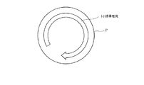
ここで、図7には、被加熱調理器具8である鍋を誘導加熱する際に、鍋の底部Pに誘導電流ieが流れる状態を平面的に示す。誘導電流ieは、誘導加熱コイル6等が発生する磁束密度の高いところに多く流れるので、誘導加熱コイル6のコイル束の中央部辺り(内径と外形との中間部分)に集中して流れる。そして、斯様な誘導電流は非磁性体で構成される発熱用導体17にも僅かに流れようとするが、折り返し形状をなすことで隣接する導体の間では互いに逆方向に流れようとするので誘起される電圧の方向も逆向きとなる。従って、発熱用導体17は誘導加熱されにくくなる。
Here, in FIG. 7, when the pan which is the
図4は、制御系の構成を示す機能ブロック図である。火力制御装置(加熱制御手段,材質判定手段,反発移動状態検出手段)21は、前記本体ケース2の内部に設けられており、マイクロコンピュータによって構成されている。火力制御装置21には、操作パネル9に配置されている操作部(操作手段)22から操作信号が入力されると共に、温度検知部11,12から温度検知信号が入力されている。そして、火力制御装置21は、これらの入力並びに予め記憶された制御プログラムに基づいて、操作パネル9に配置されている表示部23の作動を制御すると共にインバータ(高周波電流供給手段)24を制御し、誘導加熱コイル6(及び7)にインバータ24を介して高周波電流を供給して制御する。
FIG. 4 is a functional block diagram showing the configuration of the control system. The thermal power control device (heating control means, material judgment means, repulsion movement state detection means) 21 is provided inside the
また、誘導加熱コイル6には共振コンデンサ25が直列に接続されている。これらのコイル6またはコンデンサ25は、後述するように被加熱調理器具8の材質に応じて出力調整を行なうため、コイル6の巻数が可変となるように(例えば、多段コイル構成)、又はコンデンサ25の容量が可変となるように構成しても良い。
インバータ24には、商用交流電源26を整流回路27を介して直流に変換したものが駆動用電源として供給されている。また、商用交流電源26は、発熱体通電部(通電手段)28にも供給されている。発熱体通電制御部28は、発熱用導体17(及び18)に交流電源を通電するもので、その通電量は、発熱体通電制御部28を介し火力制御装置21によって制御されるようになっている。
A
The
また、整流回路27の入力側と、インバータ24の出力側とには、夫々電流トランス29,30が配置されており、それらの検知信号は火力制御装置21に与えられている。そして、火力制御装置21は、加熱調理器への入力電流ipとインバータ24の出力電流(コイル電流)icとを検出するようになっている。尚、以上において、誘導加熱コイル6及び7,インバータ24,発熱用導体17及び18,発熱体通電制御部28は,加熱手段60を構成している。
Further,
次に、本実施例の作用について図5,図6,図8も参照して説明する。図5は、火力制御装置21による制御内容を、本発明の要旨に係る部分について示すフローチャートである。火力制御装置21は、先ず、操作部22を介してユーザにより設定された入力電力の設定値を読み込むと(ステップS1)、被加熱調理器具8の材質判定を行う(ステップS2)。そして、ステップS3,S5において、高抵抗金属材料か、或いは低抵抗金属材料か否かを夫々判定する。
Next, the operation of the present embodiment will be described with reference to FIGS. FIG. 5 is a flowchart showing the contents of the control by the thermal
例えば鉄やSUS(ステンレス)といったような高抵抗金属材料か否かを判定するには、インバータ24により電圧,周波数が一定の高周波電流を誘導加熱コイル6に供給した場合、図6(a)に示すように、入力電流ipとインバータ24の出力電流であるコイル電流icとの関係に基づいて判定を行う。
即ち、被加熱調理器具8の材質が鉄などの磁性体の場合、誘導加熱コイル6が発生した磁束は被加熱調理器具8を介して流れ易くなり、被加熱調理器具8と鎖交しやすくなって漏れ磁束が少なくなるため、コイル6の等価インダクタンスL(図6(b)参照)は小さくなる。また、磁性体材料は比抵抗が大きく、表皮効果(鍋底の誘導加熱コイル6側に渦電流が集中する効果)も大きいのでコイル6の等価抵抗Rが大きくなる。一方、アルミや銅のように非磁性で比抵抗が小さい材料の場合、コイル6が発生した磁束は被加熱調理器具8に届き難くなり、漏れ磁束が多くなることでコイル6の等価インダクタンスLが大きくなる。そして、比抵抗が小さく表皮効果も小さいので等価抵抗Rも小さくなる。また、土鍋などの非金属の場合、或いは無負荷の場合は誘導電流が全く流れないので等価インダクタンスLは最も大きくなり、等価抵抗Rは最も小さくなる。
For example, in order to determine whether or not the material is a high resistance metal material such as iron or SUS (stainless steel), when a high frequency current having a constant voltage and frequency is supplied to the
That is, when the material of the cooked
そして、コイル電流icは、コイル6の等価インピーダンスZに反比例し、入力電流ipは、コイル電流icとR/Zに比例する。その結果、被加熱調理器具8の材質に応じて、図6(a)に示すような関係となる。即ち、
材質 コイル電流ic 入力電流ip
鉄 小(Rが大 →Zが大) 大(R/Zが大)
アルミ 大(Rが小 →Zが小) 小(R/Zが小)
非金属(土鍋) 小(ωLが大→Zが大) 小(R/Zが小)
従って、入力電流ip,コイル電流icの大小関係に基づいて、被加熱調理器具8の材質を判定することができる。
The coil current ic is inversely proportional to the equivalent impedance Z of the
Material Coil current ic Input current ip
Iron Small (R is large → Z is large) Large (R / Z is large)
Aluminum Large (R is small → Z is small) Small (R / Z is small)
Non-metal (earthen pot) Small (ωL is large → Z is large) Small (R / Z is small)
Therefore, the material of the cooked
そして、ステップS3において、材質が高抵抗金属材料であると判断すると(「YES」)、火力制御装置21は、ステップS1で読み込んだ入力電力設定値をインバータ24に対する入力電力として誘導加熱調理を行なう(ステップS4)。即ち、従来行われている通常の誘導加熱調理である。
一方、材質が高抵抗金属材料でない場合(ステップS3,「NO」)、火力制御装置21は、材質がアルミや銅或いは非磁性SUSのような低抵抗の非磁性金属材料か、或いは土鍋のような非金属材料(若しくは無負荷)かを判断する(ステップS5)。低抵抗金属材料であれば(「YES」)、火力制御装置21は、被加熱調理器具8の底がトッププレート3より反発移動する所謂「鍋浮き」しない状態となるように、誘導加熱調理を行なう(ステップS6)。ここで、被加熱調理器具8が鍋浮きしているか否かの判定は、例えば、特公平4−75633号公報に開示されているように、インバータ24の共振周波数の変化に基づいて行うようにする。
When it is determined in step S3 that the material is a high-resistance metal material (“YES”), the thermal
On the other hand, when the material is not a high-resistance metal material (step S3, “NO”), the thermal
そして、ステップS6において、鍋浮きしない状態となるように誘導加熱調理の火力を調整した場合に、その加熱電力とステップS1で読み込んだ入力電力設定値との間に差があれば(ステップS7,「YES」)、火力制御装置21は、その差の電力分を発熱体通電制御部28に供給してヒータ加熱を行なう(ステップS8)。また、低抵抗の非磁性金属材料の場合は誘導加熱コイル6の等価抵抗Rが小さくなるので、インバータ24を介して誘導加熱コイル6に出力する電圧を高抵抗の磁性金属材料の場合よりも低下させるか、又は電圧の周波数を上昇させる。或いは、誘導加熱コイル6の巻き数を増やしたり、共振コンデンサ25の容量を小さくする(インダクタンスLが実質的に大きくなるのに応じてCを低下させ、共振周波数を高める)ように調整して、加熱効率を向上させるようにする(ステップS9)。
In step S6, when the heating power of induction heating cooking is adjusted so that the pan does not float, if there is a difference between the heating power and the input power setting value read in step S1 (step S7, "YES"), the thermal
更に、ステップS5において、材質が低抵抗金属材料でない場合は(「NO」)、材質が非金属材料か或いは無負荷の場合である。この場合は、誘導加熱調理は行わず、ステップS1で読み込んだ入力電力設定値に等しい電力を発熱体通電制御部28に供給してヒータ加熱を行なう(ステップS10)。上述したように、入力電流ipとコイル電流icとの関係からは非金属材料と無負荷との判別ができない。従って、温度検知部11(又は12)によって、ステップS9におけるヒータ加熱開始からの温度上昇度合いを検出する(ステップS11)。 Furthermore, if the material is not a low-resistance metal material in step S5 ("NO"), this is a case where the material is a non-metal material or no load. In this case, induction heating cooking is not performed, and heater heating is performed by supplying power equal to the input power set value read in step S1 to the heating element energization control unit 28 (step S10). As described above, it is impossible to discriminate between a non-metallic material and no load from the relationship between the input current ip and the coil current ic. Accordingly, the temperature detection unit 11 (or 12) detects the degree of temperature rise from the start of heater heating in step S9 (step S11).
即ち、図8に示すように、例えばトッププレート3の載置部4に土鍋などが載置されている場合は負荷の熱容量が大きいため、加熱開始からの温度上昇度合い(立上がり)は比較的緩やかになる。これに対して、無負荷である場合は、トッププレート3の熱容量分しかないため、加熱開始からの温度上昇度合いは比較的急激になる。斯様な温度上昇度合いの相違に基づいて、非金属材料と無負荷とを判別する。そして、火力制御装置21は、無負荷であると判定すると(ステップS12,「YES」)ヒータ加熱を停止し(ステップS13)、非金属材料であると判定すると(「NO」)そのままステップS1に戻りヒータ加熱を継続する。
That is, as shown in FIG. 8, for example, when a clay pot or the like is placed on the
以上のように本実施例によれば、加熱調理器に、誘導加熱コイル6とヒータ加熱用の発熱用導体17とを備え、火力制御装置21は、被加熱調理器具8の材質を判定し、判定した材質に応じてインバータ24と発熱体通電制御部28とを制御して、誘導加熱コイル6と発熱用導体17とによる加熱割合を制御するようにした。
従って、誘導加熱では効率が低下する材質の被加熱調理器具8を加熱する場合には、発熱用導体17による加熱割合を相対的に上昇させることで効率の良い加熱を行なうことができ、被加熱調理器具8の材質に応じて誘導加熱とヒータ加熱による加熱との加熱バランスを選択できるので、様々な材質の被加熱調理器具8を高い効率で加熱することができる。
As described above, according to the present embodiment, the cooking device includes the
Therefore, when heating the cooked
具体的には、例えば被加熱調理器具8が鉄やSUSなど表皮抵抗の大きな材質か、アルミや銅など表皮抵抗の小さい材質かどうかを判定し、後者の場合は被加熱調理器具8がトッププレート3より浮かない程度の電力で誘導加熱し、残りの電力で発熱用導体17による輻射加熱を行なうことで、鍋浮きしない状態で効率の良い加熱を行なうことができる。
また、アルミや銅などの非磁性体の場合は、誘導加熱コイル6が発生した磁束が吸収されにくいため誘導加熱では磁束が漏れ易くなる。一方、発熱用導体17に通電することによって発生する磁束量は少なく且つ低周波数であるから、磁束漏れの影響が殆どない状態で加熱を行なうことができる。また、土鍋などの非金属材質の被加熱調理器具8であっても対応することができる。
Specifically, for example, it is determined whether the cooked
Further, in the case of a non-magnetic material such as aluminum or copper, the magnetic flux generated by the
また、発熱用導体17を、高抵抗の非磁性SUSによって構成したので、誘導加熱コイル6により誘導加熱されにくく、誘導加熱コイル6に供給された電力は殆ど被加熱調理器具8によって消費され、加熱効率が向上する。この場合、前記電力を被加熱調理器具8の誘導加熱電力とみなすことができるため、加熱電力を正確に把握することができ、被加熱調理器具8の材質に応じて発熱用導体17への電力配分を適切に行なうことができる。
Further, since the
また、発熱用導体17を、隣接して流れる電流の方向が互いに逆となる部分を有する形状としたので、発熱用導体17が誘導加熱されにくくなる。また、発熱用導体17に数10kHzの高周波電圧が誘起されると、その電圧は低周波数対応の発熱体通電制御部28に印加されることになり発熱体通電制御部28が破壊されるおそれがあるが、誘起電圧の発生を抑制することで破壊を防止することができる。
Further, since the
また、火力制御装置21は、発熱体通電制御部28を介し発熱用導体17に供給する入力電力値と温度検知部11によって検出される温度の上昇度合いとに基づいて、被加熱調理器具8の材質が非金属であるか、若しくは、被加熱調理器具8が存在しない無負荷の状態にあるかを判定するので、入力電流ipとコイル電流icとの関係だけでは判定することができない非金属材料と無負荷との判定が可能となる。
Further, the thermal
そして、火力制御装置21は、被加熱調理器具8の材質が非金属であると判定した場合は、インバータ24による誘導加熱コイル6への電流供給を停止して、専ら発熱用導体17によって加熱を行なうように制御するので、土鍋のような非金属材料で構成される被加熱調理器具8の加熱に寄与しない電力の供給を抑制することができる。
また、火力制御装置21は、インバータ24に供給する電力と発熱体通電制御部28に供給する電力との合計が、入力電力設定値に略等しくなるように制御するので、被加熱調理器具8の材質が様々に異なる場合でも、ユーザによって設定された入力電力によって効率よく加熱を行なうことができる。
And when the thermal-
Moreover, since the thermal
また、火力制御装置21は、被加熱調理器具8のトッププレート3からの「浮き」が検知されなくなった状態において、インバータ24に供給している電力が入力電力設定値を下回っている場合は、それらの差に相当する電力を発熱体通電制御部28に供給するので、鍋浮きのない状態で効率よく加熱を行なうことができる。
Moreover, in the state where the “floating” from the
(第2実施例)
図9は本発明の第2実施例を示すものであり、第1実施例と同一部分には同一符号を付して説明を省略し、以下異なる部分についてのみ説明する。第2実施例は、発熱用導体17に替わる発熱用導体(発熱体)31の形状が第1実施例とは異なっており、その他の構成は第1実施例と同様である。
(Second embodiment)
FIG. 9 shows a second embodiment of the present invention. The same parts as those of the first embodiment are denoted by the same reference numerals and the description thereof is omitted. Only different parts will be described below. The second embodiment is different from the first embodiment in the shape of a heat generating conductor (heating element) 31 that replaces the
図9に示すように、発熱用導体31は、同一形状の導体32,33を、配線34によって接続することで構成されている。導体32,33は、直線状の導体を内周側と外周側とで折り返しながら径方向に往復させた形状をなしている。そして、導体32,33の始端32S,33Sと、終端32E,33Eとは夫々隣り合うように配置され、導体32の終端32Eは、導体33の始端33Sと配線34によって接続されている。即ち、発熱用導体31と発熱体通電制御部28の出力端子とは、導体32の始端32S,導体32の終端33Eと接続されている。
As shown in FIG. 9, the
以上のように発熱用導体31を構成することで、導体32,33の径方向に往復する部分は、誘導加熱コイル6と直交するような位置関係となるので、コイル6が発生した磁束が導体32,33に鎖交しにくくなり誘導電流が発生しにくくなる。また、導体32,33の外周,内周部分には誘導電流が発生するが、夫々の誘導電流は、導体32,33において互いに逆方向に流れることになるので、誘起電圧の発生をキャンセルすることができる。
By configuring the
(第3実施例)
図10は本発明の第3実施例を示すものである。第3実施例は、第2実施例と同様に、異なる形状の発熱用導体(発熱体)41を用いるものである。即ち、発熱用導体41は、同一形状の導体42,43を左右対称に配置し、配線44により接続することで構成されている。導体42,43は、図10中左右に折り返しながら延びるクランク状をなしている。そして、導体42,43の始端42S,43Sと、端32E,33Eとは夫々同一側に配置され、導体42の終端42Eは、導体43の始端43Sと配線44によって接続されている。即ち、発熱用導体41と発熱体通電制御部28の出力端子とは、導体42の始端42S,導体42の終端43Eと接続されている。
以上のように発熱用導体41を構成することで、導体42,43の左右対称となる部分に発生する誘導電流が流れる方向は互いに逆方向となるので、誘起電圧の発生をキャンセルすることができる。
(Third embodiment)
FIG. 10 shows a third embodiment of the present invention. As in the second embodiment, the third embodiment uses a heat-generating conductor (heating element) 41 having a different shape. That is, the heat generating conductor 41 is configured by arranging the
By configuring the heat generating conductor 41 as described above, the directions of the induced currents generated in the symmetrical portions of the
(第4実施例)
図11は本発明の第4実施例を示すものである。第4実施例は、発熱体の構成が第1ないし第3実施例とは異なっている。即ち、第1ないし第3実施例では、何れも、発熱用導体によって被加熱調理器具8を面状に加熱するようにしたが、第4実施例では、図2相当図である図11に示すように、誘導加熱コイル6の円周中央部分において、円周をなすライン状のヒータ(発熱体)51を配置したものである。
(Fourth embodiment)
FIG. 11 shows a fourth embodiment of the present invention. The fourth embodiment is different from the first to third embodiments in the configuration of the heating element. That is, in all of the first to third embodiments, the cooked
ヒータ51は、コイルベース13において誘導加熱コイル6をよけた部分に断面が凹形状であるヒータ設置部材52を載置し、そのヒータ設置部材52の凹部に配置されている。ヒータ51としては、例えばランプ形ヒータやリボンヒータ、或いはシーズヒータなどを使用する。
また、ヒータ設置部材52には、ヒータ51が発生した熱が誘導加熱コイル6やコイルベース13側に伝導しないように断熱材としての性質を有するもの、或いは、前記熱をトッププレート3側に反射させる反射板としての性質を有するもの、また、誘導加熱コイル6が発生した磁束の影響がヒータ51側に及ばないようにする磁気シールドとしての特性を有するものを用いる。必要に応じて特性を適宜複合したものでも良い。
In the heater 51, a
The
本発明は上記し図面に記載した実施例にのみ限定されるものではなく、以下のような変形が可能である。
発熱体の形状は上記実施例にて開示したものに限ることなく、個別の設計に応じて適宜変更して実施すれば良い。
被加熱調理器具の重量を検知するように構成し、材質がアルミや銅等の被磁性体である場合には、被加熱調理器具の重量に応じて誘導加熱と発熱体による加熱との割合を制御しても良い。
The present invention is not limited to the embodiments described above and illustrated in the drawings, and the following modifications are possible.
The shape of the heating element is not limited to that disclosed in the above embodiments, and may be changed as appropriate according to the individual design.
When configured to detect the weight of the cooking utensil, and the material is a magnetic body such as aluminum or copper, the ratio of induction heating and heating by the heating element is set according to the weight of the cooking utensil. You may control.
また、誘導加熱と発熱体による加熱との割合を制御せずとも、インバータ24,発熱体通電制御部28に夫々供給する電力量を変化させて加熱を行なうものであっても良い。
第2実施例において、発熱用導体31の内周部分を埋めるように、相似形の発熱用導体を同心円状に配置しても良い。斯様に構成すれば、発熱用導体の輻射熱による加熱密度を高め、より面に近い状態で被加熱調理器具の加熱を行なうことで効率を向上させることができる。
第4実施例において、ヒータを2周以上させるように配置しても良い。
Further, the heating may be performed by changing the amount of electric power supplied to the
In the second embodiment, similar heating conductors may be arranged concentrically so as to fill the inner peripheral portion of the
In the fourth embodiment, the heater may be arranged so as to have two or more turns.
図面中、1は調理器本体、3はトッププレート、6,7は誘導加熱コイル、8は被加熱調理器具、11,12は温度検知部(温度検出手段)、17,18は発熱用導体(発熱体)、21は火力制御装置(加熱制御手段,材質判定手段,反発移動状態検出手段)、22は操作部(操作手段)、24はインバータ(高周波電流供給手段)、28は発熱体通電制御部(通電手段)、31,41は発熱用導体(発熱体)、51はヒータ(発熱体)、60は加熱手段を示す。
In the drawings, 1 is a cooker body, 3 is a top plate, 6 and 7 are induction heating coils, 8 is a cooking device to be heated, 11 and 12 are temperature detection units (temperature detection means), and 17 and 18 are heating conductors ( (Heating element), 21 is a thermal power control device (heating control means, material determination means, repulsion movement state detection means), 22 is an operation unit (operation means), 24 is an inverter (high frequency current supply means), and 28 is heating element energization control.
Claims (9)
この調理器本体の上面を構成し、被加熱調理器具が載置されるトッププレートと、
誘導加熱コイルと発熱体とで構成され、これらの少なくとも一方によって前記被加熱調理器具を加熱可能に配置される加熱手段と、
前記誘導加熱コイルに高周波電流を供給する高周波電流供給手段と、
前記発熱体に通電を行って発熱させるための通電手段と、
前記高周波電流供給手段と前記通電手段とに夫々供給する電力を制御することで、前記被加熱調理器具に対する加熱を制御する加熱制御手段と、
前記被加熱調理器具の材質を判定する材質判定手段とを備え、
前記加熱制御手段は、前記材質判定手段によって判定された材質が、高抵抗金属材料,低抵抗金属材料,非金属材料の何れであるかに応じて前記被加熱調理器具を前記誘導加熱コイルと前記発熱体とで加熱する割合を制御し、誘導加熱では効率が低下する材質の被加熱調理器具を加熱する場合には前記発熱体による加熱割合を相対的に上昇させることを特徴とする加熱調理器。 The cooker body,
A top plate that constitutes the upper surface of the cooker body, and on which the cooked utensils are placed,
A heating means that is configured by an induction heating coil and a heating element, and is arranged so as to heat the cooked utensil by at least one of these;
High-frequency current supply means for supplying a high-frequency current to the induction heating coil;
Energization means for energizing the heating element to generate heat;
Heating control means for controlling heating of the cooked utensil by controlling the power supplied to the high-frequency current supply means and the energization means ,
A material determining means for determining the material of the cooked utensil,
The heating control means is configured such that the cooking appliance is heated with the induction heating coil according to whether the material determined by the material determining means is a high resistance metal material, a low resistance metal material, or a non-metal material. to control the rate of heating by the heating element, the cooking in the induction heating when heating the cooking appliance of the material efficiency is lowered, characterized in Rukoto to a relatively high level of heat ratio by the heating element vessel.
材質判定手段は、通電手段に対する入力電力値と、前記温度検出手段によって検出される温度の上昇度合いとに基づいて、被加熱調理器具の材質が非金属であるか、若しくは、被加熱調理器具が存在しない無負荷の状態にあるかを判定することを特徴とする請求項6記載の加熱調理器。 Temperature detecting means for detecting the temperature of the cooked utensils,
The material determining means is based on the input power value to the energizing means and the degree of temperature rise detected by the temperature detecting means, or the material of the cooked utensil is non-metallic, or the cooked utensil is It is determined whether it is in the state of no load which does not exist , The heating cooker of Claim 6 characterized by the above-mentioned.
加熱制御手段は、高周波電流供給手段に供給する電力と通電手段に供給する電力との合計が、前記入力電力の設定値に略等しくなるように制御することを特徴とする請求項1乃至7の何れかに記載の加熱調理器。 Comprising an operating means for setting input power for heating the cooked utensil;
The heating control means controls the sum of the power supplied to the high-frequency current supply means and the power supplied to the energization means to be substantially equal to the set value of the input power . The heating cooker in any one.
加熱制御手段は、被加熱調理器具の反発移動が検知されなくなった状態において、高周波電流供給手段に供給している電力が入力電力設定値を下回っている場合は、それらの差に相当する電力を通電手段に供給することを特徴とする請求項8記載の加熱調理器。 Repulsion movement state detection means for detecting the repulsion movement state from the top plate of the cooked utensil ,
When the electric power supplied to the high-frequency current supply means is lower than the input power set value in a state where the repulsion movement of the cooked utensil is no longer detected , the heating control means outputs electric power corresponding to the difference between them. The cooking device according to claim 8, wherein the cooking device is supplied to an energization means .
Priority Applications (4)
| Application Number | Priority Date | Filing Date | Title |
|---|---|---|---|
| JP2004248371A JP4331071B2 (en) | 2004-08-27 | 2004-08-27 | Cooker |
| TW094128153A TWI287949B (en) | 2004-08-27 | 2005-08-18 | Heating cooker |
| CN200510097601XA CN1741689B (en) | 2004-08-27 | 2005-08-25 | Heating cooker |
| KR1020050078584A KR100681957B1 (en) | 2004-08-27 | 2005-08-26 | Heating cooker |
Applications Claiming Priority (1)
| Application Number | Priority Date | Filing Date | Title |
|---|---|---|---|
| JP2004248371A JP4331071B2 (en) | 2004-08-27 | 2004-08-27 | Cooker |
Publications (2)
| Publication Number | Publication Date |
|---|---|
| JP2006066258A JP2006066258A (en) | 2006-03-09 |
| JP4331071B2 true JP4331071B2 (en) | 2009-09-16 |
Family
ID=36093875
Family Applications (1)
| Application Number | Title | Priority Date | Filing Date |
|---|---|---|---|
| JP2004248371A Expired - Fee Related JP4331071B2 (en) | 2004-08-27 | 2004-08-27 | Cooker |
Country Status (4)
| Country | Link |
|---|---|
| JP (1) | JP4331071B2 (en) |
| KR (1) | KR100681957B1 (en) |
| CN (1) | CN1741689B (en) |
| TW (1) | TWI287949B (en) |
Cited By (1)
| Publication number | Priority date | Publication date | Assignee | Title |
|---|---|---|---|---|
| KR20220096973A (en) * | 2020-12-31 | 2022-07-07 | 엘지전자 주식회사 | Device for folding clothes |
Families Citing this family (16)
| Publication number | Priority date | Publication date | Assignee | Title |
|---|---|---|---|---|
| JP4342451B2 (en) * | 2005-01-14 | 2009-10-14 | 株式会社東芝 | Cooker |
| KR101247617B1 (en) | 2006-06-26 | 2013-04-03 | 도요 세이칸 가부시키가이샤 | Container for electromagnetic cookers |
| JP4939867B2 (en) * | 2006-08-08 | 2012-05-30 | 株式会社東芝 | Cooker |
| JP4929143B2 (en) * | 2007-12-10 | 2012-05-09 | 株式会社東芝 | Induction heating cooker |
| JP5063566B2 (en) * | 2008-11-28 | 2012-10-31 | 三菱電機株式会社 | Induction heating device |
| KR101203114B1 (en) | 2011-01-28 | 2012-11-20 | 주식회사 리홈 | Induction range having function checking pot |
| WO2012140886A1 (en) * | 2011-04-15 | 2012-10-18 | 三菱電機株式会社 | Induction heating coil, and induction heating cooking device using same |
| JP5919462B2 (en) * | 2011-12-26 | 2016-05-18 | パナソニックIpマネジメント株式会社 | Induction heating coil manufacturing method |
| JP5823022B2 (en) * | 2012-03-22 | 2015-11-25 | 三菱電機株式会社 | Induction heating cooker |
| WO2014033773A1 (en) * | 2012-08-29 | 2014-03-06 | 三菱電機株式会社 | Induction heating cooker |
| CN106658793A (en) * | 2015-11-02 | 2017-05-10 | 九阳股份有限公司 | Multifunctional cooking device |
| KR102052702B1 (en) * | 2017-06-26 | 2019-12-05 | 엘지전자 주식회사 | Coil assembly and induction heating apparatus including thereof |
| DE102017222958A1 (en) | 2017-09-04 | 2019-03-07 | E.G.O. Elektro-Gerätebau GmbH | Heating device and method for producing a heating device |
| CN111316757B (en) * | 2017-11-08 | 2022-02-18 | 三菱电机株式会社 | Induction heating cooker |
| JP6895624B2 (en) * | 2017-12-27 | 2021-06-30 | パナソニックIpマネジメント株式会社 | Induction heating cooker |
| KR20220079322A (en) * | 2020-12-04 | 2022-06-13 | 엘지전자 주식회사 | Induction heating type cooktop and operating method thereof |
Family Cites Families (3)
| Publication number | Priority date | Publication date | Assignee | Title |
|---|---|---|---|---|
| FR2748885B1 (en) * | 1996-05-14 | 1998-08-14 | Europ Equip Menager | HIGH EFFICIENCY INDUCTION COOKING FIREPLACE |
| JP2003045634A (en) | 2001-08-03 | 2003-02-14 | Matsushita Electric Ind Co Ltd | Induction heating cooker for pressure cooking |
| FR2847115B1 (en) * | 2002-11-12 | 2005-07-01 | Brandt Ind | INDUCTION DEVICE FOR INDUCTION COOKING FIREPLACE |
-
2004
- 2004-08-27 JP JP2004248371A patent/JP4331071B2/en not_active Expired - Fee Related
-
2005
- 2005-08-18 TW TW094128153A patent/TWI287949B/en not_active IP Right Cessation
- 2005-08-25 CN CN200510097601XA patent/CN1741689B/en not_active Expired - Fee Related
- 2005-08-26 KR KR1020050078584A patent/KR100681957B1/en active IP Right Grant
Cited By (2)
| Publication number | Priority date | Publication date | Assignee | Title |
|---|---|---|---|---|
| KR20220096973A (en) * | 2020-12-31 | 2022-07-07 | 엘지전자 주식회사 | Device for folding clothes |
| KR102482485B1 (en) * | 2020-12-31 | 2022-12-29 | 엘지전자 주식회사 | Device for folding clothes |
Also Published As
| Publication number | Publication date |
|---|---|
| KR20060050678A (en) | 2006-05-19 |
| TWI287949B (en) | 2007-10-01 |
| CN1741689B (en) | 2011-06-08 |
| KR100681957B1 (en) | 2007-02-15 |
| JP2006066258A (en) | 2006-03-09 |
| CN1741689A (en) | 2006-03-01 |
| TW200608836A (en) | 2006-03-01 |
Similar Documents
| Publication | Publication Date | Title |
|---|---|---|
| KR100681957B1 (en) | Heating cooker | |
| JP4342451B2 (en) | Cooker | |
| CN102342177B (en) | Induction cooking device | |
| JP4864850B2 (en) | Induction heating cooker | |
| JP4846374B2 (en) | Cooker | |
| US20120261405A1 (en) | Induction heating apparatus and induction heating cooker provided with same | |
| JP6037938B2 (en) | Induction heating cooker and control method thereof | |
| JP2008293888A (en) | Induction-heating cooker | |
| KR101307594B1 (en) | Electric range having induction heater | |
| AU2006202773B2 (en) | Heater unit and electric cooker equipped therewith | |
| JP2007335274A (en) | Induction heating cooker | |
| JP4939867B2 (en) | Cooker | |
| JP2011171040A (en) | Induction heating device, and induction heating cooking apparatus with the same | |
| JP2009123603A (en) | Induction heating cooker | |
| JP5103782B2 (en) | rice cooker | |
| JP5286182B2 (en) | Induction heating cooker | |
| JPH07106172B2 (en) | Electromagnetic heating container | |
| JP5734390B2 (en) | Induction heating cooker | |
| JP5625296B2 (en) | Induction heating device | |
| JP5289537B2 (en) | Induction heating cooker | |
| JP2018137247A (en) | Induction heating cooker | |
| JP2014017273A (en) | Induction heating cooker | |
| EP4373211A1 (en) | Induction heating type cooktop | |
| KR100832312B1 (en) | Induction autotimer for heating coil | |
| JP2009093833A (en) | Induction heating cooker |
Legal Events
| Date | Code | Title | Description |
|---|---|---|---|
| A621 | Written request for application examination |
Free format text: JAPANESE INTERMEDIATE CODE: A621 Effective date: 20070524 |
|
| A977 | Report on retrieval |
Free format text: JAPANESE INTERMEDIATE CODE: A971007 Effective date: 20080911 |
|
| A131 | Notification of reasons for refusal |
Free format text: JAPANESE INTERMEDIATE CODE: A131 Effective date: 20080924 |
|
| A521 | Request for written amendment filed |
Free format text: JAPANESE INTERMEDIATE CODE: A523 Effective date: 20081119 |
|
| TRDD | Decision of grant or rejection written | ||
| A01 | Written decision to grant a patent or to grant a registration (utility model) |
Free format text: JAPANESE INTERMEDIATE CODE: A01 Effective date: 20090526 |
|
| A01 | Written decision to grant a patent or to grant a registration (utility model) |
Free format text: JAPANESE INTERMEDIATE CODE: A01 |
|
| A61 | First payment of annual fees (during grant procedure) |
Free format text: JAPANESE INTERMEDIATE CODE: A61 Effective date: 20090617 |
|
| R150 | Certificate of patent or registration of utility model |
Ref document number: 4331071 Country of ref document: JP Free format text: JAPANESE INTERMEDIATE CODE: R150 Free format text: JAPANESE INTERMEDIATE CODE: R150 |
|
| FPAY | Renewal fee payment (event date is renewal date of database) |
Free format text: PAYMENT UNTIL: 20120626 Year of fee payment: 3 |
|
| FPAY | Renewal fee payment (event date is renewal date of database) |
Free format text: PAYMENT UNTIL: 20130626 Year of fee payment: 4 |
|
| S111 | Request for change of ownership or part of ownership |
Free format text: JAPANESE INTERMEDIATE CODE: R313115 |
|
| R350 | Written notification of registration of transfer |
Free format text: JAPANESE INTERMEDIATE CODE: R350 |
|
| S531 | Written request for registration of change of domicile |
Free format text: JAPANESE INTERMEDIATE CODE: R313531 |
|
| S533 | Written request for registration of change of name |
Free format text: JAPANESE INTERMEDIATE CODE: R313533 |
|
| R350 | Written notification of registration of transfer |
Free format text: JAPANESE INTERMEDIATE CODE: R350 |
|
| S111 | Request for change of ownership or part of ownership |
Free format text: JAPANESE INTERMEDIATE CODE: R313117 |
|
| R371 | Transfer withdrawn |
Free format text: JAPANESE INTERMEDIATE CODE: R371 |
|
| S111 | Request for change of ownership or part of ownership |
Free format text: JAPANESE INTERMEDIATE CODE: R313117 |
|
| S531 | Written request for registration of change of domicile |
Free format text: JAPANESE INTERMEDIATE CODE: R313531 |
|
| R350 | Written notification of registration of transfer |
Free format text: JAPANESE INTERMEDIATE CODE: R350 |
|
| S111 | Request for change of ownership or part of ownership |
Free format text: JAPANESE INTERMEDIATE CODE: R313113 |
|
| R371 | Transfer withdrawn |
Free format text: JAPANESE INTERMEDIATE CODE: R371 |
|
| S111 | Request for change of ownership or part of ownership |
Free format text: JAPANESE INTERMEDIATE CODE: R313113 |
|
| R350 | Written notification of registration of transfer |
Free format text: JAPANESE INTERMEDIATE CODE: R350 |
|
| RD02 | Notification of acceptance of power of attorney |
Free format text: JAPANESE INTERMEDIATE CODE: R3D02 |
|
| LAPS | Cancellation because of no payment of annual fees |