JP4326694B2 - Linear accelerator - Google Patents
Linear accelerator Download PDFInfo
- Publication number
- JP4326694B2 JP4326694B2 JP2000531038A JP2000531038A JP4326694B2 JP 4326694 B2 JP4326694 B2 JP 4326694B2 JP 2000531038 A JP2000531038 A JP 2000531038A JP 2000531038 A JP2000531038 A JP 2000531038A JP 4326694 B2 JP4326694 B2 JP 4326694B2
- Authority
- JP
- Japan
- Prior art keywords
- cavity
- axis
- linear accelerator
- cavities
- cylindrical
- Prior art date
- Legal status (The legal status is an assumption and is not a legal conclusion. Google has not performed a legal analysis and makes no representation as to the accuracy of the status listed.)
- Expired - Lifetime
Links
Images


Classifications
-
- H—ELECTRICITY
- H05—ELECTRIC TECHNIQUES NOT OTHERWISE PROVIDED FOR
- H05H—PLASMA TECHNIQUE; PRODUCTION OF ACCELERATED ELECTRICALLY-CHARGED PARTICLES OR OF NEUTRONS; PRODUCTION OR ACCELERATION OF NEUTRAL MOLECULAR OR ATOMIC BEAMS
- H05H9/00—Linear accelerators
- H05H9/04—Standing-wave linear accelerators
-
- H—ELECTRICITY
- H05—ELECTRIC TECHNIQUES NOT OTHERWISE PROVIDED FOR
- H05H—PLASMA TECHNIQUE; PRODUCTION OF ACCELERATED ELECTRICALLY-CHARGED PARTICLES OR OF NEUTRONS; PRODUCTION OR ACCELERATION OF NEUTRAL MOLECULAR OR ATOMIC BEAMS
- H05H7/00—Details of devices of the types covered by groups H05H9/00, H05H11/00, H05H13/00
- H05H7/14—Vacuum chambers
- H05H7/18—Cavities; Resonators
Landscapes
- Physics & Mathematics (AREA)
- Engineering & Computer Science (AREA)
- Plasma & Fusion (AREA)
- Spectroscopy & Molecular Physics (AREA)
- Particle Accelerators (AREA)
- Microwave Tubes (AREA)
Description
【0001】
【発明の属する技術分野】
本発明は線形加速器に関するものである。
【0002】
【従来の技術及び発明が解決しようとする課題】
特に定常波設計の線形加速器は、例えばX線の発生に使用するための電子ビーム源として知られている。この電子ビームがX線ターゲットに対して送られ、このターゲットが適当な放射線を放射する。このようなX線または電子ビームの通常の用途は医学的癌治療などである。
【0003】
X線ターゲットに対する電子ビームの入射エネルギーを変更することがしばしば必要となる。これは、特に治療プロフィルによって特定のエネルギーが要求されるような医療上のケースである。線形定常波加速器は一連の加速キャビティを含み、これらのキャビティが連結キャビティによって相互に連結され、これらの連結キャビティが隣接の加速キャビティ対と連通する。US-A-4382208 によれば、電子ビームのエネルギーは隣接加速キャビティ間のrf連結の程度を調整することによって変動される。これは原則的に連結キャビティの幾何学的形状を変更することによって達成される。
【0004】
この幾何学的形状の変動は代表的には連結キャビティの中に1つまたは複数の位置に挿入することのできる滑り要素を使用してキャビティの内部形状を変更することによって実施される。このアプローチについては、キャビティの寸法によって決定される他の種々の共鳴パラメータから生じる多数の深刻な問題点がある。キャビティ間の位相ずれを正確に確定された値に保持するため、このような1つ以上の滑り要素を動かさなければならない場合がしばしばである。滑り要素の運動は通常同等でないので、これらの滑り要素は個別に運動させなければならないが、所望の位相関係が保持されるようにこれらの要素が相互にまたキャビティに対して非常に精密に配置されなければならない。通常、±0.2mmの精度が要求される。これは、実際上加工することの困難な複雑で高精密の位置づけシステムを必要とする。(米国特許第4,286,192号に記載のような)2以下の可動部分を有する設計においては、装置は入力と出力との間に一定位相を保持する事ができないので、このような装置はRF電場を連続的に変動させる事ができず、従って単一スイッチの機能に帰着する。これらの装置は実際上しばしばエネルギースイッチと呼ばれる。
【0005】
またこれらの設計の多くは、大振幅のRF電流を搬送しなければならない複数の滑り接点を提案している。このような接点は溶接によって誘導される焼き付きによって故障する傾向があり、また滑り面は超高真空システムの品質にとって有害である。このような問題点が長寿命にわたって確実に作動することのできる装置を製造するための手がかりとなる。
【0006】
先行技術において提案された方法の本質は1つの入力孔と1つの出力孔とを有するキャビティ連結手段と要約され、この組立体全体が電気的に変圧器と同様に作動する。可変的連結値を得るために、キャビティの形状がなんらかの方法でベロー、チョーク、およびフランジを使用して変更されなければならなかった。しかし先行技術は、位相を一定値に保持しながら、単一の制御軸によって連結のマグニチュードを広い範囲内で連続的に変動させることのできる装置を提供していない。
【0007】
従って現在の技術水準においては、2つの所定エネルギー間の有効な切り替え法を提供するものとしてこのような装置が受け入れられる。しかし、このような設計を使用して真に可変的なエネルギー出力を提供する信頼できる加速器を得ることが非常に困難である。
【0008】
先行技術のすぐれた要約が米国特許第4,746,839号に記載されている。
【0009】
【課題を解決するための手段】
従って本発明は、粒子ビーム軸線にそって配置された複数の共鳴キャビティを含み、少なくとも一対の共鳴キャビティが連結キャビティを通して電磁的に連結され、前記連結キャビティはその軸線回りに実質的に回転対称であるがこの対称を破るように成された非回転対称要素を含み、前記要素は連結キャビティの中を回転自在であって、その回転が連結キャビティの対称軸線に対して実質的に平行であるように成された定常波線形加速器を提供する。
【0010】
このような装置においては、加速キャビティ中の共鳴に対して横方向の共鳴が連結キャビティの中において成立される。加速キャビティについてはTMモードの共鳴を使用するのが通常であり、これは連結キャビティ中においてTE111などのTEモードが成立することを意味する。連結キャビティは実質的に回転対称であるので、この電界の配向は連結キャビティによっては確定されない。その代わりに、電界配向は回転要素によって確定される。連結キャビティと2つの加速キャビティ間の連通は連結キャビティの表面上の2点において生じ、これらの点がTE定常波の配向に依存して相異なる磁界を「見る」であろう。従って単に回転要素を回転させる事によって、連結の程度が変更される。
【0011】
真空キャビティ中の回転要素の回転は公知の技術であって、この回転をなすために多くの方法が存在する。従ってこれは深刻な技術的困難を提示しない。さらに渦電流は回転要素そのものに閉じ込められ、一般に回転要素と周囲構造とを橋かけ結合することを必要としない。従って溶接は困難を生じない。
【0012】
またその設計は技術的公差に対して柔軟である。予備的テストは、40゜の連結レンジにわたって2%の位相安定性を得るためには2dBの精度で十分であることが示された。この程度の回転精度を得るのは困難ではない。
【0013】
回転要素が無限回転対称の連結キャビティの中で自由に回転する事が好ましい。このような構造によって、最大適応性を有する装置が得られる。
【0014】
適当な回転要素は対称軸線にそって配置されたパドルである。パドルがキャビティ幅の半分と四分の三の範囲内を占める事が好ましく、キャビティ幅の約2/3が適当である。このような限度内にあればパドルとキャビティ表面との間の縁部相互作用が最小限となる。
【0015】
共鳴キャビティの軸線は好ましくは粒子ビーム軸線に対して横方向とする。これはrf相互作用を簡単化する。
【0016】
加速キャビティは好ましくは連結キャビティ上に設定されたポートを通して相互に連通する。前記ポートは40゜乃至140゜の範囲内の角度で離間された連結キャビティの半径上に配置される事が好ましい。さらに好ましい範囲は60゜乃至120゜である。特に好ましい範囲は80乃至100゜の範囲内である。すなわち約90゜である。
【0017】
これらのポートはキャビティ端面上に、すなわち対称軸線に対して横方向に配置され、またはキャビティの円筒面上に配置されることができる。後者の構造はよりコンパクトな構造を与え、より大きな連結を生じる可能性がある。
【0018】
従って本発明は、TEモードで、特にTEIIIモードで作動する特殊キャビティを通して隣接セルを連結する新規な方法を提供する。入力孔と出力孔の連結位置をキャビティの一方の端壁を成す円の弦に沿うように選択する事によって、TEIIIモードの特殊フィーチャを利用して独特の利点を有する連結装置を構成することができる。本発明はキャビティの形状を変更する代わりに、簡単なパドルを使用してキャビティ内部でTEIIIモードの偏極を回転させることを提案する。TEIIIモードの周波数は電界パタンがキャビティに対して成す角度(偏極角度)には依存しないので、2点の中に連結されるRFの相対位相はこの回転に対して少なくとも180゜にわたって不変である。同時に、1つの弦にそって位置する2つの連結孔におけるRF磁界の相対マグニチュードは2位数のマグニチュードまで変動する。このRF磁界の特性が本発明の可変RFカプラーの基礎である。
【0019】
本発明の理解の手がかりは、可動パドルが先行技術の場合のようにキャビティの形状を変動させる手段ではなく、単に円筒形キャビティの円形対称を破る手段であることにある。パドルそのものはキャビティの壁面と接触する必要がなく、またパドルとキャビティ壁体との間にRF電流そのものは流れない。これは装置の真空中製造を簡単化し、回転フィード・スルーのみを必要とし、これは公知の技術である。さもなければ、パドルを外部磁界によって回転させて真空フィード・スルーを完全に排除することができる。
【0020】
【発明の実施の形態】
定常波加速器においては、装置は図2および図3に図示の第1実施態様のように構成されることができよう。これらの図は、長い加速キャビティ連鎖の一部として軸線上に配置された3加速セルを示す。第1および第2加速セル10,12はそれ自体公知の固定ゼオメトリー連結セル16と相互に連結されている。第2および第3軸線キャビティ12と14との間においては、固定ゼオメトリーセルの代わりに本発明によるセル18が配置されている。このセル18は、その円筒体が加速セル12,14のアーチの上端と交差して2つの任意形状の連結孔26,28を形成されている。所望のように機能するために、これらの孔が理想的には軸線からそれた円筒体の(非直径)弦にそっていなければならない。これは、図3に図示のように円筒体の中心線が加速器の中心線から片寄ってることを意味する。これらの連結孔は磁界が支配するキャビティ区域の中にあるので、セル間の連結は磁性となる。しかし固定ゼオメトリーセルと相違し、この場合にはセル間の連結、従って第2および第3軸線セルにおけるRF電界の比率を変動させる簡単な手段が存在する。連結強さ(k)は孔の形状と孔の位置におけるRF磁界の局所的値とに依存している。軸線上の電界はk値の比率と逆比例的に変動する。従って、下記の式が得られる。
【0021】
(E1/E2)=(k2/k1)
端壁に近い磁界パタンは、連結が弦にそって配置されていれば、k1がk2の減少に従って増大することを意味する。
【0022】
回転自在のパドル(仕切り板とも呼ぶ)20がキャビティ18の中に軸22によって保持され、この軸22が円筒形キャビティ18の外部に延在している。図2に図示のように、軸22はハンドル24を有してパドル20を回転させるが、ハンドルの代わりに他の適当なアクチュエータを使用できることは明かである。
【0023】
パドル20はキャビティ18の対称性を破って電界の電気線をパドル面に対して垂直に配置させる。
【0024】
このようにして得られる結果は単一の可動部分を有する装置であって、この可動部分が回転に際してセル間の連結を直接に制御することができ、同時に入力と出力間の相対位相シフトを固定的に、すなわち呼びπラジアンに保持することができる。このシステム中の唯一の自由度はパドルの回転角度である。代表的な定常波加速器用途においては、このパドル回転角度は数度の精度で配置されればよい。このような制御により、線形加速器のエネルギーを広いエネルギー範囲にわたって連続的に調整することができよう。
【0025】
図4と図5による第2実施態様によれば、連結キャビティ30は前記の実施態様と同様に加速キャビティの縦方向軸線に対して横方向にあるが、その円筒形面によって加速キャビティ12,14と交差する。従って加速器の軸線と連結キャビティの軸線は交差することなく、相互に横方向に延在する。パドル20などは不変である。他の点ではこの実施態様の動作は第1実施態様と同様である。
【0026】
図6乃至図10は本発明の第3実施態様を示す。これらの図において、2つの加速キャビティと両側の2つの連結キャビティの半体とからなる線形加速器の短いサブ要素を示す。さらにこのサブ要素は、2つの加速キャビティを連結した本発明による単一連結キャビティを含む。加速器全体は軸方向に接合されたこのような数個のサブ要素からなるであろう。
【0027】
図6において、加速キャビティの軸線100は小さい開口102を通して第1加速キャビティ104(図6において図示されず)の中に入る。他の加速キャビティ108は開口106を通して第1加速キャビティ104と連通する。第2キャビティ108は反対側面に他のアパチュア110を有し、この実施態様のサブ要素が軸線100にそって反復配置された時に形成される後続の加速キャビティと連通する。従って加速されるビームはアパチュア102,106,110などを通して順次に通過する。
【0028】
図示のサブ要素の中に一対の連結半キャビティが形成される。第1半キャビティ112が、第1加速キャビティ104と隣接サブ要素によって形成される隣接加速キャビティとの間に固定強さの連結を成す。この隣接サブ要素が連結キャビティ112の残余の半体を成す。同様に第2連結キャビティ114が第2加速キャビティ108を隣接要素によって形成される隣接加速キャビティに連結する。各連結半キャビティは直立ポスト116,118を含み、これらのポストは所望の適当レベルの連結を生じるように各キャビティを調整する。各連結キャビティ112,114はその構造において通常のものである。
【0029】
第1加速キャビティ104は第2加速キャビティ108に対して調整自在連結キャビティ120を介して連結される。この連結キャビティは要素中の円筒形スペースからなり、この円筒形の軸線は加速器軸線100から横方向にあってこの軸線から離間されている。これら2つの軸線の最接近点における間隔と円筒形の半径は、円筒形が加速キャビティ104,108と交差してアパチュア122,124を生じるように調整される。この実施態様に図示のように、円筒形120は第2加速キャビティ108の方に少し近く配置されて、アパチュア124をアパチュア122より大きく成している。加速器の他の部分の設計によってはこれは場合によっては有利でありうるが、これは本質的なことではなく、他の設計においては望ましくない場合がある。
【0030】
調整自在連結キャビティ120の一端に、アパチュア126が形成されて軸128をキャビティ内部に入らせる。軸128はアパチュア126において公知の方法で回転自在に密封される。調整自在キャビティ120の中において、軸128はパドル130を支持し、従ってこのパドルは回転自在に配置されて、調整自在連結キャビティ120中のTE111電界の配向を確定し、従って第1キャビティ104と第2キャビティ108との間の連結量を決定する。
【0031】
構造全体に冷却水を導入できるように、サブ要素中に冷却チャンネルが形成されている。この実施例において、加速チャンネルの回りに等間隔で配置された全部で4冷却チャンネルが備えられている。2つの冷却チャンネル132,134は固定連結キャビティ112,114の上下を走り装置全体をまっすぐに通る。他の2つの冷却チャンネル136,138は可変キャビティ120と同一側面にそって走る。これらの冷却チャンネルが加速キャビティ104,108または調整自在連結キャビティ120と衝突することを防止するため、図7と図8において最もよく見られるように、一対のドッグ・レッグ140が形成されている。
【0032】
図8は実施例の構成法を示す分解斜視図である。中心ベース・ユニット150は連結キャビティと第1および第2加速キャビティ104,108の2つの半体とを収容する。2つの加速キャビティは、銅基板上に適当な旋削を実施し、これに続いてこれら2つのキャビティ間の中心連通アパチュア106を穿孔し、同時に冷媒チャンネル132,134,136,138と、チャンネル136,138のドッグ・レッグとを形成する。次に調整自在連結キャビティ120を穿孔し、このようにして連結キャビティ120と2つの加速キャビティ104,108との間のアパチュア122,124を形成する。次にキャップ152,154を調整自在連結キャビティ120の上端と下端にロウ付けし、密封する。
【0033】
次に中心ユニット150の両側面にロウ付け段階によって取付けるためのエンドピース156,158を形成することができる。この場合には、連結キャビティ104,108の他方の半体を前記の半キャビティ112,114と同様にしてこれらのユニット156,158の中に切削することができる。冷媒チャンネル132,134,136および138を軸方向連通通路102,110と同様にして穿孔することができる。次にエンドピースを中心ユニットの両側にロウ付け配置し、加速キャビティを密封して単一ユニットを形成する。
【0034】
複数の同様のユニットを端−端ロウ付けして加速キャビティ連鎖を形成することができる。隣接対の加速キャビティが固定連結キャビティを介して連結され、またこのような加速キャビティ対の各部材が調整自在連結キャビティ120を介して隣接キャビティ対の部材に連結される。
【0035】
このようなユニットのロウ付けは業界公知であって、単に各部分の間に適当な共融ロウ付け合金のホイルを挟持して締付け、この組立体を適当な高温まで加熱する段階を含む。冷却後に隣接キャビティは確実に接合される。
【0036】
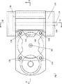
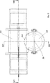
図11乃至図14は本発明の第4実施例を示す。第3実施例と同様にこの実施例は2つの加速キャビティを含む線形加速器のサブ要素を示す。図示のような複数のサブ要素を端−端接合して作動加速器を形成することができる。
【0037】
一対の加速セル204,208が加速軸線200にそって配列されている。アパチュア202が加速ビームを隣接要素から加速キャビティ204の中に入らせ、さらにアパチュア206がビームを連続的に加速キャビティ208の中に入らせ、次にアパチュア210がビームを軸線200にそって加速キャビティ208から他のキャビティの中に入らせる。
【0038】
2つの加速キャビティ204,208を相互に接続する調整自在連結キャビティ220が形成されている。この連結キャビティ220は円筒体からなり、その軸線は加速器軸線200に対して横方向に延在しこの軸線から離間されている。円筒体の半径とその軸線の位置は、円筒体が加速キャビティ204,208と交差して連通アパチュア222,224を成すように成されている。図示のように、調整自在連結キャビティ220は加速キャビティ204に近く配置されているので、アパチュア222はアパチュア224より少し大である。しかしこれはすべての状況において本質的なのではなく、加速器の残余部分の構成に依存している。
【0039】
調整自在連結キャビティ220を形成する円筒体は端面260,262を有し、これらの端面は円筒体220の軸線にそって線形に調整自在である。従って連結キャビティの長さは加速器の外部設計に対応するように変動させることができる。この長さは加速器の共鳴周波数に従って設定される必要がある。しかし実験的研究は、この設定が特に正確である必要のないことを示している。
【0040】
端壁262は軸方向アパチュア226を有し、このアパチュアを通して軸228が延在する。端壁262の外側面にハンドル264が形成され、また端壁の内側面にパドル230が形成されている。このパドル230は調整自在連結キャビティ220の回転対称を破ってTE111電界の配向を固定するのに役立つ。このようにして電界の配向、従って連結のマグニチュードがハンドル264の調整によって変動させられる。手動調整ハンドルの代わりに適当な機械的アクチュエータを使用できることは明かである。
【0041】
第3実施態様および第4実施態様に記載のような調整自在連結キャビティは2つの加速キャビティの間に0%乃至6%の範囲内の連結係数を生じうることが発見された。大部分の加速器設計は4%までの連結係数を必要とするので、この設計は実質的にすべての事態に対して必要な連結レベルを生じることができる。
【0042】
本発明によれば、加速キャビティ間の位相ずれを乱すことなく、連続的連結定数範囲を得ることができる。さらに第3実施態様は、製造容易な要素から成長性のある加速器を構築することを可能とする。
【0043】
本発明は前記の説明のみに限定されるものでなく、その趣旨の範囲内において任意に変更実施できる。
【図面の簡単な説明】
【図1】 TE111円筒形キャビティモードの電界線を示す図。
【図2】 本発明の第1実施態様による定常波線形加速器の縦方向断面図。
【図3】 図2のIII-III線にそった断面図。
【図4】 本発明の第2実施態様による定常波線形加速器の縦方向断面図。
【図5】 図4のV−V断面図。
【図6】 本発明の第3実施態様の線形加速器の斜視図。
【図7】 図6の実施態様の軸方向断面図。
【図8】 図6の実施態様の分解斜視図。
【図9】 図7のIX−IX断面図。
【図10】 図7のX−X断面図。
【図11】 本発明の第4実施態様の斜視図。
【図12】 図11の実施態様の加速器軸線にそった断面図。
【図13】 図12のXIII-XIII断面図。
【図14】 図12のXIV-XIV断面図。[0001]
BACKGROUND OF THE INVENTION
The present invention relates to a linear accelerator.
[0002]
[Prior art and problems to be solved by the invention]
In particular, a linear accelerator with a standing wave design is known as an electron beam source for use in generating X-rays, for example. This electron beam is sent to an X-ray target, which emits appropriate radiation. Typical uses for such X-rays or electron beams are medical cancer treatments and the like.
[0003]
It is often necessary to change the incident energy of the electron beam on the X-ray target. This is especially the medical case where specific energy is required by the treatment profile. A linear standing wave accelerator includes a series of accelerating cavities that are interconnected by connecting cavities that communicate with adjacent pairs of accelerating cavities. According to US-A-4382208, the energy of the electron beam is varied by adjusting the degree of rf coupling between adjacent acceleration cavities. This is achieved in principle by changing the geometry of the connecting cavity.
[0004]
This geometric variation is typically accomplished by changing the internal shape of the cavity using a sliding element that can be inserted into the connecting cavity at one or more locations. There are a number of serious problems with this approach that arise from various other resonance parameters determined by the dimensions of the cavity. Often one or more such sliding elements must be moved in order to keep the phase shift between the cavities at an accurately determined value. Since the movement of the sliding elements is usually not equal, these sliding elements must be moved individually, but they are placed very precisely relative to each other and to the cavity so that the desired phase relationship is maintained. It must be. Usually, accuracy of ± 0.2mm is required. This requires a complex and high precision positioning system that is difficult to machine in practice. In designs with 2 or fewer moving parts (as described in US Pat. No. 4,286,192), such devices cannot maintain a constant phase between input and output, so such devices can generate an RF electric field. It cannot be continuously varied, thus resulting in the function of a single switch. These devices are often often called energy switches in practice.
[0005]
Many of these designs also propose multiple sliding contacts that must carry large amplitude RF currents. Such contacts tend to fail due to welding induced seizures and sliding surfaces are detrimental to the quality of ultra high vacuum systems. Such problems provide clues for manufacturing devices that can operate reliably over a long lifetime.
[0006]
The essence of the method proposed in the prior art is summarized as a cavity coupling means having one input hole and one output hole, and the entire assembly operates electrically like a transformer. In order to obtain a variable coupling value, the shape of the cavity had to be changed in some way using bellows, chokes and flanges. However, the prior art does not provide a device that can continuously vary the magnitude of the connection within a wide range by a single control axis while maintaining the phase at a constant value.
[0007]
Therefore, in the current state of the art, such a device is accepted as providing an effective switching method between two predetermined energies. However, it is very difficult to obtain a reliable accelerator that provides a truly variable energy output using such a design.
[0008]
A good summary of the prior art is described in US Pat. No. 4,746,839.
[0009]
[Means for Solving the Problems]
Accordingly, the present invention includes a plurality of resonant cavities arranged along a particle beam axis, wherein at least a pair of resonant cavities are electromagnetically connected through the connecting cavities, the connecting cavities being substantially rotationally symmetric about the axis. A non-rotationally symmetric element that is configured to break this symmetry, but said element is rotatable in the coupling cavity so that its rotation is substantially parallel to the symmetry axis of the coupling cavity. A standing wave linear accelerator is provided.
[0010]
In such a device, a resonance in the transverse direction is established in the coupling cavity with respect to the resonance in the acceleration cavity. For acceleration cavities, it is common to use TM mode resonance, which means that TE modes such as TE111 are established in the connected cavities. Since the coupling cavity is substantially rotationally symmetric, this electric field orientation is not determined by the coupling cavity. Instead, the electric field orientation is determined by the rotating element. Communication between the coupling cavity and the two acceleration cavities occurs at two points on the surface of the coupling cavity, and these points will “see” different magnetic fields depending on the orientation of the TE standing wave. Therefore, the degree of connection is changed by simply rotating the rotating element.
[0011]
The rotation of the rotating element in the vacuum cavity is a known technique and there are many ways to achieve this rotation. This therefore presents no serious technical difficulties. Furthermore, eddy currents are confined to the rotating element itself and generally do not require bridging and coupling the rotating element and surrounding structures. Therefore, welding does not cause difficulty.
[0012]
The design is also flexible to technical tolerances. Preliminary tests have shown that an accuracy of 2 dB is sufficient to obtain 2% phase stability over a 40 ° coupling range. It is not difficult to obtain such rotational accuracy.
[0013]
It is preferred that the rotating element rotates freely in an infinite rotationally symmetrical connected cavity. With such a structure, a device with maximum adaptability is obtained.
[0014]
A suitable rotating element is a paddle arranged along the axis of symmetry. It is preferred that the paddle occupy within half and three quarters of the cavity width, with about 2/3 of the cavity width being adequate. Within such limits, edge interaction between the paddle and the cavity surface is minimized.
[0015]
The axis of the resonant cavity is preferably transverse to the particle beam axis. This simplifies the rf interaction.
[0016]
The acceleration cavities are preferably in communication with each other through ports set on the connecting cavities. The ports are preferably located on the radii of connecting cavities spaced at an angle in the range of 40 ° to 140 °. A more preferred range is 60 ° to 120 °. A particularly preferred range is in the range of 80 to 100 °. That is, about 90 °.
[0017]
These ports can be arranged on the cavity end face, i.e. transversely to the axis of symmetry, or on the cylindrical face of the cavity. The latter structure gives a more compact structure and may result in a larger connection.
[0018]
The present invention thus provides a novel method of connecting adjacent cells through special cavities operating in TE mode, particularly in TEIII mode. By selecting the connection position of the input hole and the output hole along the circular chord forming one end wall of the cavity, it is possible to construct a connection device having unique advantages by utilizing the special feature of the TEIII mode. it can. The present invention proposes to rotate TEIII mode polarization inside the cavity using a simple paddle instead of changing the shape of the cavity. Since the frequency of the TEIII mode does not depend on the angle formed by the electric field pattern with respect to the cavity (polarization angle), the relative phase of the RF coupled into the two points is invariant over this rotation by at least 180 °. . At the same time, the relative magnitude of the RF magnetic field in the two coupling holes located along one string varies to a magnitude of two orders. This characteristic of the RF magnetic field is the basis of the variable RF coupler of the present invention.
[0019]
The key to understanding the present invention is that the movable paddle is not a means to vary the shape of the cavity as in the prior art, but merely a means to break the circular symmetry of the cylindrical cavity. The paddle itself does not need to contact the cavity wall and no RF current itself flows between the paddle and the cavity wall. This simplifies the production of the device in vacuum and requires only a rotary feed-through, which is a known technique. Otherwise, the paddle can be rotated by an external magnetic field to completely eliminate vacuum feedthrough.
[0020]
DETAILED DESCRIPTION OF THE INVENTION
In a standing wave accelerator, the device could be configured as in the first embodiment illustrated in FIGS. These figures show a three-acceleration cell placed on the axis as part of a long acceleration cavity chain. The first and
[0021]
(E 1 / E 2 ) = (k 2 / k 1 )
A magnetic field pattern close to the end wall means that k1 increases as k2 decreases if the connections are arranged along the strings.
[0022]
A rotatable paddle (also referred to as a partition plate) 20 is held in a
[0023]
The
[0024]
The result thus obtained is a device with a single movable part, which can directly control the connection between the cells during rotation and at the same time fix the relative phase shift between the input and the output. In other words, it can be held at nominal π radians. The only degree of freedom in this system is the paddle rotation angle. In typical standing wave accelerator applications, the paddle rotation angle may be arranged with an accuracy of several degrees. Such control would allow the linear accelerator energy to be continuously adjusted over a wide energy range.
[0025]
According to the second embodiment according to FIGS. 4 and 5, the connecting
[0026]
6 to 10 show a third embodiment of the present invention. In these figures, a short sub-element of a linear accelerator consisting of two acceleration cavities and two connected cavity halves on either side is shown. Furthermore, this sub-element comprises a single connected cavity according to the invention connecting two acceleration cavities. The entire accelerator will consist of several such sub-elements joined in the axial direction.
[0027]
In FIG. 6, the
[0028]
A pair of connected half cavities are formed in the illustrated sub-element. A first half-
[0029]
The
[0030]
An
[0031]
Cooling channels are formed in the sub-elements so that cooling water can be introduced throughout the structure. In this embodiment, there are a total of four cooling channels arranged at equal intervals around the acceleration channel. The two
[0032]
FIG. 8 is an exploded perspective view showing a configuration method of the embodiment. The
[0033]
Next,
[0034]
Multiple similar units can be end-to-end brazed to form an accelerated cavity chain. Adjacent pairs of acceleration cavities are connected through fixed connection cavities, and each member of such an acceleration cavity pair is connected to members of an adjacent cavity pair through
[0035]
Brazing of such units is well known in the art and involves simply clamping a suitable eutectic braze alloy foil between the parts and heating the assembly to a suitable high temperature. Adjacent cavities are securely joined after cooling.
[0036]
11 to 14 show a fourth embodiment of the present invention. Like the third embodiment, this embodiment shows a linear accelerator sub-element that includes two acceleration cavities. A plurality of sub-elements as shown can be end-to-end joined to form an actuating accelerator.
[0037]
A pair of
[0038]
An
[0039]
The cylindrical body forming the
[0040]
[0041]
It has been discovered that an adjustable coupling cavity as described in the third and fourth embodiments can produce a coupling factor in the range of 0% to 6% between the two acceleration cavities. Since most accelerator designs require a coupling factor of up to 4%, this design can produce the necessary coupling level for virtually all situations.
[0042]
According to the present invention, a continuous coupling constant range can be obtained without disturbing the phase shift between the acceleration cavities. Furthermore, the third embodiment makes it possible to construct a growth accelerator from easily manufactured elements.
[0043]
The present invention is not limited to the above description, and can be arbitrarily changed within the scope of the gist.
[Brief description of the drawings]
FIG. 1 is a diagram showing electric field lines in a TE 111 cylindrical cavity mode.
FIG. 2 is a longitudinal sectional view of a standing wave linear accelerator according to a first embodiment of the present invention.
3 is a cross-sectional view taken along line III-III in FIG.
FIG. 4 is a longitudinal sectional view of a standing wave linear accelerator according to a second embodiment of the present invention.
5 is a cross-sectional view taken along line VV in FIG.
FIG. 6 is a perspective view of a linear accelerator according to a third embodiment of the present invention.
7 is an axial cross-sectional view of the embodiment of FIG.
8 is an exploded perspective view of the embodiment of FIG.
9 is a cross-sectional view taken along line IX-IX in FIG.
10 is a sectional view taken along line XX in FIG.
FIG. 11 is a perspective view of a fourth embodiment of the present invention.
12 is a cross-sectional view along the accelerator axis of the embodiment of FIG.
13 is a sectional view taken along line XIII-XIII in FIG.
14 is a cross-sectional view taken along the line XIV-XIV in FIG.
Claims (9)
前記仕切り板は、円筒形の直径の半分以上四分の三以下の範囲内を占めることを特徴とする請求項4に記載の線形加速器。 The connecting cavity is cylindrical,
5. The linear accelerator according to claim 4, wherein the partition plate occupies a range of not less than half and not more than three quarters of a cylindrical diameter .
前記ポートはキャビティの端面上に配置されることを特徴とする請求項2に記載の線形加速器。 The connecting cavity is cylindrical,
The linear accelerator according to claim 2 , wherein the port is disposed on an end face of the cavity.
前記ポートはキャビティの円筒面上に配置されることを特徴とする請求項2に記載の線形加速器。 The connecting cavity is cylindrical,
The linear accelerator according to claim 2, wherein the port is disposed on a cylindrical surface of the cavity.
Applications Claiming Priority (3)
| Application Number | Priority Date | Filing Date | Title |
|---|---|---|---|
| GB9802332.8 | 1998-02-05 | ||
| GB9802332A GB2334139B (en) | 1998-02-05 | 1998-02-05 | Linear accelerator |
| PCT/GB1999/000187 WO1999040759A1 (en) | 1998-02-05 | 1999-02-05 | Linear accelerator |
Publications (3)
| Publication Number | Publication Date |
|---|---|
| JP2002503024A JP2002503024A (en) | 2002-01-29 |
| JP2002503024A5 JP2002503024A5 (en) | 2009-05-21 |
| JP4326694B2 true JP4326694B2 (en) | 2009-09-09 |
Family
ID=10826411
Family Applications (1)
| Application Number | Title | Priority Date | Filing Date |
|---|---|---|---|
| JP2000531038A Expired - Lifetime JP4326694B2 (en) | 1998-02-05 | 1999-02-05 | Linear accelerator |
Country Status (10)
| Country | Link |
|---|---|
| US (1) | US6376990B1 (en) |
| EP (1) | EP1053661B1 (en) |
| JP (1) | JP4326694B2 (en) |
| KR (1) | KR20010040273A (en) |
| CN (1) | CN1196384C (en) |
| CA (1) | CA2316942C (en) |
| DE (1) | DE69901599T2 (en) |
| ES (1) | ES2178387T3 (en) |
| GB (1) | GB2334139B (en) |
| WO (1) | WO1999040759A1 (en) |
Families Citing this family (30)
| Publication number | Priority date | Publication date | Assignee | Title |
|---|---|---|---|---|
| GB2354875B (en) * | 1999-08-06 | 2004-03-10 | Elekta Ab | Linear accelerator |
| GB2354876B (en) * | 1999-08-10 | 2004-06-02 | Elekta Ab | Linear accelerator |
| US6646383B2 (en) * | 2001-03-15 | 2003-11-11 | Siemens Medical Solutions Usa, Inc. | Monolithic structure with asymmetric coupling |
| US6465957B1 (en) * | 2001-05-25 | 2002-10-15 | Siemens Medical Solutions Usa, Inc. | Standing wave linear accelerator with integral prebunching section |
| US6657391B2 (en) * | 2002-02-07 | 2003-12-02 | Siemens Medical Solutions Usa, Inc. | Apparatus and method for establishing a Q-factor of a cavity for an accelerator |
| ITMI20022608A1 (en) * | 2002-12-09 | 2004-06-10 | Fond Di Adroterapia Oncologic A Tera | LINAC WITH DRAWING TUBES FOR THE ACCELERATION OF A BAND OF IONS. |
| US7206379B2 (en) * | 2003-11-25 | 2007-04-17 | General Electric Company | RF accelerator for imaging applications |
| US7339320B1 (en) * | 2003-12-24 | 2008-03-04 | Varian Medical Systems Technologies, Inc. | Standing wave particle beam accelerator |
| CN100358397C (en) * | 2004-02-01 | 2007-12-26 | 绵阳高新区双峰科技开发有限公司 | Phase (energy) switch-standing wave electronic linear accelerator |
| US7558374B2 (en) * | 2004-10-29 | 2009-07-07 | General Electric Co. | System and method for generating X-rays |
| US7345435B1 (en) * | 2004-12-13 | 2008-03-18 | Jefferson Science Associates Llc | Superstructure for high current applications in superconducting linear accelerators |
| GB2424120B (en) * | 2005-03-12 | 2009-03-25 | Elekta Ab | Linear accelerator |
| WO2007069931A1 (en) * | 2005-12-12 | 2007-06-21 | Obschestvo S Ogranichennoi Otvetstvennostyu 'nauka I Tekhnologii' | Low-injection energy continuous linear electron accelerator |
| FR2949289B1 (en) * | 2009-08-21 | 2016-05-06 | Thales Sa | ELECTRONIC ACCELERATION HYPERFREQUENCY DEVICE |
| US8760050B2 (en) * | 2009-09-28 | 2014-06-24 | Varian Medical Systems, Inc. | Energy switch assembly for linear accelerators |
| DE102009048150A1 (en) * | 2009-10-02 | 2011-04-07 | Siemens Aktiengesellschaft | Accelerator and method for controlling an accelerator |
| US8284898B2 (en) * | 2010-03-05 | 2012-10-09 | Accuray, Inc. | Interleaving multi-energy X-ray energy operation of a standing wave linear accelerator |
| US20120229024A1 (en) | 2011-03-10 | 2012-09-13 | Elekta Ab (Publ) | Electron source for linear accelerators |
| US8552667B2 (en) * | 2011-03-14 | 2013-10-08 | Elekta Ab (Publ) | Linear accelerator |
| JP5812969B2 (en) * | 2012-11-07 | 2015-11-17 | 三菱重工業株式会社 | Accelerating tube |
| CN103906340B (en) * | 2012-12-28 | 2017-04-12 | 清华大学 | Standing wave electron linear accelerator device and method thereof |
| GB2513596B (en) | 2013-04-30 | 2020-01-01 | Elekta Ab | Image-guided radiotherapy |
| KR102598740B1 (en) * | 2015-05-12 | 2023-11-03 | 티에이이 테크놀로지스, 인크. | Systems and methods for reducing unwanted eddy currents |
| CN105722298B (en) * | 2016-03-22 | 2021-03-16 | 上海联影医疗科技股份有限公司 | Accelerating tube |
| WO2018204714A1 (en) * | 2017-05-05 | 2018-11-08 | Radiabeam Technologies, Llc | Compact high gradient ion accelerating structure |
| WO2018222839A1 (en) | 2017-06-01 | 2018-12-06 | Radiabeam Technologies, Llc | Split structure particle accelerators |
| KR20210003748A (en) * | 2018-04-25 | 2021-01-12 | 아담 에스.에이. | Variable energy proton linear accelerator system and method of operating a proton beam suitable for irradiating tissue |
| US11612049B2 (en) | 2018-09-21 | 2023-03-21 | Radiabeam Technologies, Llc | Modified split structure particle accelerators |
| CN109954228B (en) * | 2018-12-25 | 2021-03-12 | 江苏海明医疗器械有限公司 | Electronic radiation field image system positioning device for medical accelerator |
| US20220087005A1 (en) * | 2018-12-28 | 2022-03-17 | Shanghai United Imaging Healthcare Co., Ltd. | Accelerating apparatus for a radiation device |
Family Cites Families (6)
| Publication number | Priority date | Publication date | Assignee | Title |
|---|---|---|---|---|
| USRE22990E (en) * | 1938-04-14 | 1948-03-23 | Modulation system | |
| US2391016A (en) * | 1941-10-31 | 1945-12-18 | Sperry Gyroscope Co Inc | High-frequency tube structure |
| US4024426A (en) * | 1973-11-30 | 1977-05-17 | Varian Associates, Inc. | Standing-wave linear accelerator |
| US4382208A (en) | 1980-07-28 | 1983-05-03 | Varian Associates, Inc. | Variable field coupled cavity resonator circuit |
| US4400650A (en) * | 1980-07-28 | 1983-08-23 | Varian Associates, Inc. | Accelerator side cavity coupling adjustment |
| US4629938A (en) * | 1985-03-29 | 1986-12-16 | Varian Associates, Inc. | Standing wave linear accelerator having non-resonant side cavity |
-
1998
- 1998-02-05 GB GB9802332A patent/GB2334139B/en not_active Expired - Fee Related
-
1999
- 1999-02-05 ES ES99904947T patent/ES2178387T3/en not_active Expired - Lifetime
- 1999-02-05 JP JP2000531038A patent/JP4326694B2/en not_active Expired - Lifetime
- 1999-02-05 EP EP99904947A patent/EP1053661B1/en not_active Expired - Lifetime
- 1999-02-05 CN CNB998011037A patent/CN1196384C/en not_active Expired - Lifetime
- 1999-02-05 DE DE69901599T patent/DE69901599T2/en not_active Expired - Lifetime
- 1999-02-05 WO PCT/GB1999/000187 patent/WO1999040759A1/en not_active Application Discontinuation
- 1999-02-05 KR KR1020007005407A patent/KR20010040273A/en not_active Application Discontinuation
- 1999-02-05 CA CA002316942A patent/CA2316942C/en not_active Expired - Lifetime
- 1999-02-05 US US09/529,757 patent/US6376990B1/en not_active Expired - Lifetime
Also Published As
| Publication number | Publication date |
|---|---|
| CN1196384C (en) | 2005-04-06 |
| CA2316942A1 (en) | 1999-08-12 |
| GB9802332D0 (en) | 1998-04-01 |
| CN1273761A (en) | 2000-11-15 |
| KR20010040273A (en) | 2001-05-15 |
| EP1053661A1 (en) | 2000-11-22 |
| EP1053661B1 (en) | 2002-05-29 |
| DE69901599T2 (en) | 2002-11-07 |
| GB2334139B (en) | 2001-12-19 |
| CA2316942C (en) | 2005-06-28 |
| DE69901599D1 (en) | 2002-07-04 |
| JP2002503024A (en) | 2002-01-29 |
| GB2334139A (en) | 1999-08-11 |
| ES2178387T3 (en) | 2002-12-16 |
| WO1999040759A1 (en) | 1999-08-12 |
| US6376990B1 (en) | 2002-04-23 |
Similar Documents
| Publication | Publication Date | Title |
|---|---|---|
| JP4326694B2 (en) | Linear accelerator | |
| US7339320B1 (en) | Standing wave particle beam accelerator | |
| US6504303B2 (en) | Optical magnetron for high efficiency production of optical radiation, and 1/2λ induced pi-mode operation | |
| EP1201107B1 (en) | Linear accelerator | |
| EP1859660B1 (en) | Linear accelerator | |
| EP0514585A2 (en) | Charged particle accelerator | |
| US6876288B2 (en) | Transverse field bitter-type magnet | |
| US4885470A (en) | Integrally formed radio frequency quadrupole | |
| US5334943A (en) | Linear accelerator operable in TE 11N mode | |
| US4746833A (en) | Coupled cavity travelling wave tubes | |
| EP0062599B1 (en) | Slow wave structure for a backward wave oscillator tube | |
| CN112770475B (en) | Power-adjustable waveguide device, accelerator comprising same and adjusting method thereof | |
| JPH0529097A (en) | Resonant frequency controller for high frequency electron gun | |
| JP2860266B2 (en) | Variable energy type high frequency quadrupole accelerator and ion implanter | |
| US4237431A (en) | Five port waveguide switch | |
| JPH01264200A (en) | Standing wave linear accelerator | |
| Cavallari et al. | Coupler developments at CERN | |
| JP2001052897A (en) | High frequency linear accelerator | |
| JPH01149337A (en) | Variable high frequency cavity resonator | |
| JPH0378302A (en) | High frequency acceleration cavity | |
| NZ533139A (en) | Optical magnetron for high efficiency production of optical radiation, and 1/2 wavelength induced pi-mode | |
| JP2001217488A (en) | Gas laser oscillation device |
Legal Events
| Date | Code | Title | Description |
|---|---|---|---|
| A621 | Written request for application examination |
Free format text: JAPANESE INTERMEDIATE CODE: A621 Effective date: 20060202 |
|
| A131 | Notification of reasons for refusal |
Free format text: JAPANESE INTERMEDIATE CODE: A131 Effective date: 20081205 |
|
| A601 | Written request for extension of time |
Free format text: JAPANESE INTERMEDIATE CODE: A601 Effective date: 20090305 |
|
| A602 | Written permission of extension of time |
Free format text: JAPANESE INTERMEDIATE CODE: A602 Effective date: 20090312 |
|
| A524 | Written submission of copy of amendment under article 19 pct |
Free format text: JAPANESE INTERMEDIATE CODE: A524 Effective date: 20090402 |
|
| TRDD | Decision of grant or rejection written | ||
| A01 | Written decision to grant a patent or to grant a registration (utility model) |
Free format text: JAPANESE INTERMEDIATE CODE: A01 Effective date: 20090515 |
|
| A01 | Written decision to grant a patent or to grant a registration (utility model) |
Free format text: JAPANESE INTERMEDIATE CODE: A01 |
|
| A61 | First payment of annual fees (during grant procedure) |
Free format text: JAPANESE INTERMEDIATE CODE: A61 Effective date: 20090610 |
|
| FPAY | Renewal fee payment (event date is renewal date of database) |
Free format text: PAYMENT UNTIL: 20120619 Year of fee payment: 3 |
|
| R150 | Certificate of patent or registration of utility model |
Free format text: JAPANESE INTERMEDIATE CODE: R150 |
|
| FPAY | Renewal fee payment (event date is renewal date of database) |
Free format text: PAYMENT UNTIL: 20130619 Year of fee payment: 4 |
|
| R250 | Receipt of annual fees |
Free format text: JAPANESE INTERMEDIATE CODE: R250 |
|
| R250 | Receipt of annual fees |
Free format text: JAPANESE INTERMEDIATE CODE: R250 |
|
| R250 | Receipt of annual fees |
Free format text: JAPANESE INTERMEDIATE CODE: R250 |
|
| R250 | Receipt of annual fees |
Free format text: JAPANESE INTERMEDIATE CODE: R250 |
|
| R250 | Receipt of annual fees |
Free format text: JAPANESE INTERMEDIATE CODE: R250 |
|
| R250 | Receipt of annual fees |
Free format text: JAPANESE INTERMEDIATE CODE: R250 |
|
| EXPY | Cancellation because of completion of term |