JP4324079B2 - Image encoding apparatus and method, computer program, and computer-readable storage medium - Google Patents
Image encoding apparatus and method, computer program, and computer-readable storage medium Download PDFInfo
- Publication number
- JP4324079B2 JP4324079B2 JP2004331106A JP2004331106A JP4324079B2 JP 4324079 B2 JP4324079 B2 JP 4324079B2 JP 2004331106 A JP2004331106 A JP 2004331106A JP 2004331106 A JP2004331106 A JP 2004331106A JP 4324079 B2 JP4324079 B2 JP 4324079B2
- Authority
- JP
- Japan
- Prior art keywords
- encoding
- encoded data
- image
- lossless
- block
- Prior art date
- Legal status (The legal status is an assumption and is not a legal conclusion. Google has not performed a legal analysis and makes no representation as to the accuracy of the status listed.)
- Expired - Fee Related
Links
Images


Description
本発明は画像データの符号化に関するものである。 The present invention relates to encoding of image data.
一般に、画像の圧縮符号化する場合には、画像を適当なサイズのタイルに分割し、このタイル単位に符号化を行う。自然画の場合には、復号結果で画質劣化が目立たないJPEG(非可逆符号化)で圧縮符号化し、網点パターンは、JPEGでは逆に劣化を抑えることが難しいので、可逆符号化方式を用いることが望ましい。 In general, when compressing and encoding an image, the image is divided into tiles of an appropriate size and encoding is performed in units of tiles. In the case of a natural image, compression encoding is performed with JPEG (lossy encoding) in which the degradation of image quality is not noticeable in the decoding result, and the halftone dot pattern is difficult to suppress degradation with JPEG. Therefore, a lossless encoding method is used. It is desirable.
このようなタイル単位に適応的に符号化方式を選択する技術では、各タイルを符号化するに先立ち、各タイルが自然画タイルであるか、文字/線画等のタイルであるかについて、判断することが多い(特許文献1、2)。
しかしながら、上記文献に開示されている技術においては、各タイルに対して、属性が正しく判断されることを前提にしており、その判断は実のところは難しいという問題がある。現実には、適応的に符号化方式が選択されているとは限らず、網点の領域中に可逆符号化が適用された可逆タイルと、非可逆符号化が適用された非可逆タイルが混在することがあり、大きな画質劣化を招いていた。 However, the technique disclosed in the above document is based on the premise that the attribute is correctly determined for each tile, and there is a problem that the determination is actually difficult. In reality, the encoding method is not necessarily selected adaptively, and a lossless tile to which lossless encoding is applied and a lossy tile to which lossy encoding is applied are mixed in a halftone dot region. In some cases, the image quality was greatly degraded.
本発明はかかる問題点に鑑みなされたものであり、特に網点の属性を有するような画像データを符号化した場合であっても、画質劣化の発生を抑制し、高い画質の画像を復号することを可能ならしめる技術を提供しようとするものである。 The present invention has been made in view of such problems, and even when image data having a halftone dot attribute is encoded, the occurrence of image quality deterioration is suppressed and a high quality image is decoded. We intend to provide technology that makes things possible.
この課題を解決するため、例えば本発明の画像符号化装置は以下の構成を備える。すなわち、
画像データを入力し、符号化する画像符号化装置であって、
画像データを所定サイズのブロックに分割する分割手段と、
分割されたブロックが網点画像の属性を有する否かを判定する判定手段と、
分割されたブロックについて可逆符号化し、可逆符号化データを生成する可逆符号化手段と、
分割されたブロックについて非可逆符号化し、非可逆符号化データを生成する非可逆符号化手段と、
前記判定手段によって、注目ブロックが網点画像の属性を有すると判定された場合、前記可逆符号化手段で生成された可逆符号化データを選択し、注目ブロックが網点画像の属性を有さないと判定された場合には、前記可逆符号化手段及び前記非可逆符号化手段それぞれで生成された符号化データのデータ量を重み付け比較し、データ量の少ない符号化データを選択し、出力する選択手段と、
前記選択手段で選択されたブロック毎の符号化データを結合して、所定の符号化データ列として出力する出力手段とを備える。
In order to solve this problem, for example, an image encoding device of the present invention has the following configuration. That is,
An image encoding device for inputting and encoding image data,
A dividing means for dividing the image data into blocks of a predetermined size;
Determining means for determining whether or not the divided block has the attribute of a halftone image;
A lossless encoding means for performing lossless encoding on the divided blocks and generating lossless encoded data;
Irreversible encoding means for irreversibly encoding the divided blocks and generating irreversible encoded data;
By the determination unit, the block of interest when it is determined to have attributes of halftone image, select lossless encoded data generated by the reversible coding means, the block of interest does not have the attributes of the halftone image If it is determined that the data amount of the encoded data generated by each of the lossless encoding unit and the lossy encoding unit is weighted and compared, the encoded data with a small amount of data is selected and output is selected. Means,
Output means for combining the encoded data for each block selected by the selecting means and outputting as a predetermined encoded data string.
本発明によれば、網点属性を有する領域については、2つの符号化手段の符号量とは無関係に、可逆符号化が行われることにより、可逆、非可逆が混在することによる画質劣化を防ぐことが可能になる。また、網点領域以外では、重み付け比較により符号量の少ない符号化データが選択されることにより、1ページ分の総符号化データも少ないものとすることができる。 According to the present invention, an area having a halftone dot attribute is subjected to lossless encoding regardless of the code amounts of the two encoding means, thereby preventing image quality deterioration due to a mixture of lossless and lossy. It becomes possible. In addition, in areas other than the halftone dot area, the encoded data with a small code amount is selected by weighted comparison, so that the total encoded data for one page can be reduced.
以下添付図面を参照して、本発明を好適な実施形態に従って詳細に説明する。 Hereinafter, the present invention will be described in detail according to preferred embodiments with reference to the accompanying drawings.
[第1の実施形態]
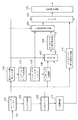
図1は本実施形態に係る画像処理装置のブロック構成図である。
[First Embodiment]
FIG. 1 is a block diagram of an image processing apparatus according to this embodiment.
図1に示すように、本実施形態に係る画像処理装置は、ストライプバッファ101、ブロック分割部102、タイルバッファ103、有効レベル数カウント部104、インデックステーブル用メモリ105、インデックス変換部106、セレクタ107、タイルデータ可逆符号化部108、可逆符号列形成部109、インデックステーブル生成部113、タイルデータ非可逆符号化部114、セレクタ115、符号列形成部116、分散算出部117とを備える。また、符号110、111、112は信号線(バス)を示している。
As shown in FIG. 1, the image processing apparatus according to the present embodiment includes a
本実施形態に係る画像処理装置の符号化対象とする画像データは、RGBカラー画像データであり、各コンポーネント(色)は8ビットで、それぞれ0〜255の範囲の輝度値を表現した画素データにより構成されるものとする。符号化対象の画像データの並びは点順次、即ち、ラスタースキャン順に各画素を並べ、その各画素はR,G,Bの順番でデータを並べて構成されるものとする。信号線110より入力される符号化対象の画像データは水平方向W画素、垂直方向H画素により構成されるものとする。
The image data to be encoded by the image processing apparatus according to the present embodiment is RGB color image data, each component (color) is 8 bits, and pixel data that represents a luminance value in the range of 0 to 255. Shall be composed. Assume that the image data to be encoded is arranged in the order of dots, that is, in the raster scan order, and the pixels are arranged in the order of R, G, and B. It is assumed that image data to be encoded input from the
以下、図1を参照して、本実施形態に係る画像処理装置が行う画像符号化処理について説明する。 Hereinafter, with reference to FIG. 1, an image encoding process performed by the image processing apparatus according to the present embodiment will be described.
符号化対象画像データは信号線110から、ラスタースキャン順に入力される。
The encoding target image data is input from the
ストライプバッファ101は画像データを所定のライン数(Th)分格納する領域を持ち、信号線110から入力される画像データを順次格納していく。
The
以降、符号化対象画像データをThラインの幅で分割した部分的な画像データをストライプデータもしくは単にストライプと呼ぶ。ストライプバッファ101に必要とされる容量、即ち1ストライプのデータ量はW×Th×3(RGB分)バイトである。説明の便宜上、垂直方向画素数HはThの整数倍であるとし、画像の末尾で不完全なストライプが発生しないものとする。
Hereinafter, partial image data obtained by dividing the encoding target image data by the width of the Th line is referred to as stripe data or simply stripe. The capacity required for the
ストライプバッファ101に1ストライプの画像データ、即ち、Thライン分の画像データが格納されるとブロック分割部102はストライプバッファ101に格納されるThライン分の画像データを水平方向Tw画素、垂直方向Th画素で構成される矩形ブロックに分割して、ブロック単位に読み出してタイルバッファ103へと格納する。説明の便宜上、画像の水平方向に並ぶ画素数WはTwの整数倍であるとし、矩形ブロックに分割した場合に不完全なブロックが発生しないものとする。この水平方向Tw画素、垂直方向Th画素で構成される矩形ブロックを以降ではタイルデータもしくは単にタイルと呼ぶ。
When one stripe of image data, that is, image data for Th lines is stored in the
タイルバッファ103は、1タイル分の画素データを格納する領域を持ち、ブロック分割部102から出力されるタイルデータを順次格納していく。よってタイルバッファ103に必要とされる最低容量はTw×Th×3(RGB分)バイトである。タイルバッファ103に格納される1タイル分の画素データの水平方向画素位置x、垂直方向画素位置yにある画素のコンポーネントcの輝度値をP(x、y、c)と定義する。xは0からTw−1まで、yは0からTh−1まで、cはR,G,Bのいずれかである。
The
有効レベル数カウント部104は、タイルバッファ103に格納される1タイルの画素データについて、コンポーネント毎に、そこで使用されている輝度レベル数(言い換えると、何種類の輝度レベルが使われているか)をカウントする。
The effective level
以降、タイル内にて使用されている輝度レベルを有効レベルと呼び、その個数を有効レベル数と呼び、R、G、Bの各コンポーネントの有効レベル数をそれぞれNLV(R)、NLV(G)、NLV(B)として表す。 Hereinafter, the luminance level used in the tile is referred to as an effective level, the number thereof is referred to as the effective level number, and the effective level numbers of the R, G, and B components are respectively NLV (R) and NLV (G). , Expressed as NLV (B).
有効レベル数カウント部104はその内部に図5に示すようなフラグの配列F(c,i)を保持する。cはコンポーネントを表し、R,G,Bのいずれかである。iは輝度値を表し、0〜255のいずれかの値である。フラグF(c,i)=0は着目するタイルのコンポーネントcにおいて輝度値iが出現しないことを意味し、フラグF(c、i)=1はタイルのコンポーネントcにおいて輝度値iが出現することを意味する。
The effective level
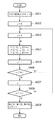
図6は有効レベル数カウント部104の処理の流れを示すフローチャートである。以下、図6に示したフローチャートを参照して、有効レベル数カウント部104の行う処理について説明する。
FIG. 6 is a flowchart showing a processing flow of the valid level number counting
まず、有効レベル数カウント部104の内部に保持するフラグ配列F(c,i)を全て0に初期化する(ステップS601)。
First, all the flag arrays F (c, i) held in the valid level number counting
次に、タイル内垂直方向画素位置を示す変数yを0に設定する(ステップS602)。 Next, a variable y indicating the vertical pixel position in the tile is set to 0 (step S602).
同様にタイル内水平方向画素位置を示す変数xを0に設定する(ステップS603)。 Similarly, a variable x indicating the horizontal pixel position in the tile is set to 0 (step S603).
タイルバッファ103に格納されるP(x,y,R)、P(x,y,G)、P(x,y,B)を参照し、フラグ配列F(R,P(x,y,R))、F(G,P(x,y,G))、F(B,P(x,y,B))に1を設定する(ステップS604)。
Referring to P (x, y, R), P (x, y, G), and P (x, y, B) stored in the
例えば、タイル内の位置x、yのR、G、Bの値がそれぞれ10、20、30である場合、
F(R、10)←1
F(G、20)←1
F(B、30)←1
とし、R成分の有効レベル“10”が存在したことを示す情報をセットする。G、B成分についても同様である。
For example, if the values of R, G, B at positions x, y in the tile are 10, 20, 30 respectively,
F (R, 10) ← 1
F (G, 20) ← 1
F (B, 30) ← 1
And information indicating that the effective level “10” of the R component exists is set. The same applies to the G and B components.
次に、タイル内垂直方向画素位置を示す変数xに“1”を加算する(ステップS605)。そして、変数xとタイルの水平方向画素数Twを比較し、x<Twの場合(YES)にはステップS604に処理を移して右隣の画素について処理を行い、そうでない場合(NO)にはステップS607へと処理を移す。 Next, “1” is added to the variable x indicating the vertical pixel position in the tile (step S605). Then, the variable x is compared with the horizontal pixel count Tw of the tile. If x <Tw (YES), the process proceeds to step S604 to perform the process on the right adjacent pixel, and otherwise (NO). The process moves to step S607.
ステップS607ではタイル内垂直方向画素位置を示す変数yに“1”を加算する(ステップS607)。 In step S607, “1” is added to the variable y indicating the vertical pixel position in the tile (step S607).
変数yとタイルの垂直方向画素数Thを比較し、y<Thの場合(YES)にはステップS603に処理を戻し、上記処理を繰り返す。 The variable y is compared with the vertical pixel count Th of the tile. If y <Th (YES), the process returns to step S603 and the above process is repeated.
以上の処理を、タイルの全画素について処理すると、そのタイル内に出現した各色成分の有効レベルが判明する。したがって、ステップS609では、各色成分毎の有効レベル数NLV(R)、NLV(G)、NLV(B)は次のようにして求めることができる。
NLV(R)=ΣF(R,i)
NLV(G)=ΣF(G,i)
NLV(B)=ΣF(B,i)
ここで『Σ』はi=0〜255までの累積加算を示すものである。
When the above processing is performed for all the pixels of the tile, the effective level of each color component appearing in the tile is determined. Therefore, in step S609, the effective level numbers NLV (R), NLV (G), and NLV (B) for each color component can be obtained as follows.
NLV (R) = ΣF (R, i)
NLV (G) = ΣF (G, i)
NLV (B) = ΣF (B, i)
Here, “Σ” indicates cumulative addition from i = 0 to 255.
以上の処理により各コンポーネントの有効レベル数NLV(c)(cはR、G、Bのいずれか)を生成し、出力する。 Through the above processing, the effective level number NLV (c) (c is any of R, G, and B) of each component is generated and output.
インデックステーブル用メモリ105には図7に示すようなインデックス変換テーブルIDX(c、i)を保持する。
The
ここでも、cはコンポーネントを表し、R,G,Bのいずれかであり、iは輝度値を表し、0〜255のいずれかの値である。このインデックス変換テーブルIDX(c、i)は後述するインデックス変換部106において輝度値をインデックス値に変換する際に参照される。
Here, c represents a component and is any one of R, G, and B, i represents a luminance value, and is any value from 0 to 255. This index conversion table IDX (c, i) is referred to when the luminance value is converted into an index value in the
インデックステーブル生成部113は有効レベル数カウント部104に保持されているフラグ配列F(c,i)を参照して、インデックステーブル用メモリ105にインデックス変換テーブルIDX(c、i)を生成する。同時に符号列に付加情報として含めて伝送するための変換テーブル情報を可逆符号列形成部109へと出力する。
The index table generating unit 113 refers to the flag array F (c, i) held in the valid level
図8はインデックステーブル生成部113の処理の流れを示すフローチャートである。この処理は、各コンポーネント毎の、出現した有効レベル(F(c,i)=1となっている輝度)に0、1、2とインデックス番号を割り当てるものである。
FIG. 8 is a flowchart showing a processing flow of the index table generation unit 113. In this process,
以下、図8に示したフローチャートを参照して、インデックステーブル生成部113の行う処理について説明する。インデックステーブル生成部113によるインデックステーブル生成の処理はコンポーネント毎に行われるが、各コンポーネント毎の処理は同一であるので、ここではコンポーネントをcとして処理を説明する。 Hereinafter, processing performed by the index table generating unit 113 will be described with reference to the flowchart shown in FIG. The index table generation processing by the index table generation unit 113 is performed for each component. Since the processing for each component is the same, the processing will be described assuming that the component is c.
まず、インデックステーブル用メモリ105の内部に保持するインデックス変換テーブルIDX(c,i)を全て−1等のインデックスとしてあり得ない値で初期化する(ステップS801)。
First, all the index conversion tables IDX (c, i) held in the
次に、輝度値を示す変数iに0を初期設定し(ステップS802)、インデックス値を表す変数idx(c)を0に初期化する(ステップS803)。 Next, the variable i indicating the luminance value is initialized to 0 (step S802), and the variable idx (c) representing the index value is initialized to 0 (step S803).
次いで、有効レベル数カウント部104に保持されているフラグ配列F(c,i)を参照し、着目する輝度値iについてF(c,i)=1かどうかを判断する(ステップS804)。
Next, with reference to the flag array F (c, i) held in the valid level
F(c,i)=1である場合(YES)はステップS805へ、そうでない場合(NO)はステップS807へと処理を移す。 If F (c, i) = 1 (YES), the process proceeds to step S805; otherwise (NO), the process proceeds to step S807.
F(c,i)=1である場合、コンポーネントcの輝度値iが注目タイル内に存在したことを示すことを意味するので、ステップS805にて、IDX(c,i)にidx(c)を設定するとともに、idx(c)を可逆符号列形成部109へ出力する(ステップS805)。 When F (c, i) = 1, it means that the luminance value i of the component c is present in the tile of interest, so in step S805 IDx (c, i) is set to idx (c). Is set and idx (c) is output to the lossless code string forming unit 109 (step S805).
続いてidx(c)に1を加えて値を更新する(ステップS806)。 Subsequently, 1 is added to idx (c) to update the value (step S806).
ステップS807では輝度値を示す変数iに1を加えて更新し(ステップS807)、変数iと256と比較し、i<256である場合(YES)にはステップS804に処理を戻して次の輝度値について処理を継続し、それ以外の場合(NO)にはステップS809へと処理を移す。 In step S807, the variable i indicating the luminance value is updated by adding 1 (step S807). When the variable i is compared with 256, if i <256 (YES), the process returns to step S804 to return to the next luminance. The process is continued for the value, and in other cases (NO), the process proceeds to step S809.
ステップS809では1つのコンポーネントについての付加情報の終了コードとして値−1を可逆符号列形成部109へと出力する。
In step S809, the value −1 is output to the lossless code
以上の処理をR,G,B各コンポーネントについて順番に行い、インデックステーブル用メモリ105内部にインデックステーブル用メモリを生成する。
The above processing is performed in order for each of the R, G, and B components, and an index table memory is generated in the
着目するタイルについて、有効レベル数カウント部104による有効レベル数カウント処理と、インデックステーブル生成部113によるインデックステーブル生成処理が終了すると、インデックス変換部106、セレクタ107、タイルデータ予測符号化部108により、タイルバッファ103に格納されるタイルデータの符号化処理を開始する。
When the effective level number counting process by the effective level
本実施形態の画像符号化装置では、タイルの符号化データをコンポーネント順に読み出して符号化する。即ち、まず、タイルのRコンポーネントを先ず符号化し、続いてGコンポーネント、Bコンポーネントの順に符号化していく。各コンポーネントについてはタイル内をラスタースキャン順にデータを読み出して符号化処理を行う。各コンポーネントの符号化処理は共通であるので、以下、コンポーネントをcとして符号化処理を説明する。 In the image encoding apparatus according to the present embodiment, encoded data of tiles is read and encoded in the order of components. That is, the R component of the tile is first encoded, and then the G component and B component are encoded in this order. For each component, the data is read out in the tiles in the raster scan order and encoded. Since the encoding process of each component is common, the encoding process will be described below with component c.
インデックス変換部106はインデックステーブル用メモリ105に格納されるインデックス変換テーブルIDX(c,i)を参照して、タイルバッファ103からコンポーネント順、ラスタースキャン順に読み出される輝度値P(x,y,c)をインデックス値IDX(c、P(x、y、c))に置き換えて出力する。
The
セレクタ107はタイルバッファ103から順次読み出される画素値P(x,y,c)とインデックス変換部106から出力されるインデックス値IDX(c、P(x,y,c))を受け取り、そのいずれか一方を選択して出力する。セレクタ107内部には所定の閾値ML(タイルサイズに依存して決定されることが望ましい)を保持しておき、有効レベル数カウント部104から出力される有効レベルNLV(c)と閾値MLを比較し、NLV(c)<MLである場合にはインデックス変換された値、即ちインデックス変換部106からの入力値を選択して出力し、NLV(c)≧MLである場合にはインデックス変換されていない値P(x,y,c)を選択して出力する。
The
タイルデータ可逆符号化部108は、信号線111から入力される画素値、またはインデックス値を可逆符号化して符号列を信号線112を介して可逆符号列形成部109へと出力する。
The tile data
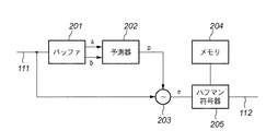
タイルデータ可逆符号化部108の内部は可逆符号化方式であれば適用可能であり、例えば、連続階調静止画像の可逆及び準可逆圧縮の国際標準として勧告されるJPEG−LS(ISO/IEC14495−1および2)などを適用することができる。ここでは、図2に示すブロック構成図で示される構成になっているものとする。
The inside of the tile data
同図に於いて201はバッファ、202は予測器、203は減算器、204はメモリ、205はハフマン符号化器である。図2は、画像データを予測誤差に変換する系列変換の処理に周辺画素を用いた予測変換を用い、符号化処理にはハフマン符号化を用いる画像圧縮方式の例である。 In the figure, 201 is a buffer, 202 is a predictor, 203 is a subtractor, 204 is a memory, and 205 is a Huffman encoder. FIG. 2 shows an example of an image compression method that uses predictive conversion using peripheral pixels for the series conversion process for converting image data into prediction errors, and uses Huffman coding for the encoding process.
同図において、実際の符号化が行われる前に、予め幾つかの画像を示す画像データを系列変換して得られた予測誤差の頻度分布を調べ、これに応じてハフマンテーブルを作成し、メモリ204に格納される。 In the figure, before actual encoding is performed, the frequency distribution of prediction errors obtained by series conversion of image data representing several images is examined in advance, and a Huffman table is created in accordance with the frequency distribution. 204.
予測誤差の頻度分布の一般的性質として予測誤差0を中心として出現頻度が高く、予測誤差の絶対値が大きくなるにつれて出現頻度が下がっていく傾向にあるため、メモリ204に格納されるハフマン符号では予測誤差0近辺に短い符号語が割り当てられ、予測誤差の絶対値が大きい部分には長い符号語が割り当てられる。
As a general property of the frequency distribution of the prediction error, the appearance frequency is high centering on the
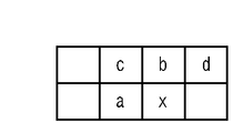
最初に信号線111からタイルデータが順に入力される。バッファ201は信号線111から入力されるタイルデータを2ライン分格納する。予測器202はバッファ201から符号化対象画素の直前の画素aと,1ライン前の同じ水平位置の画素bのタイルデータ(図3参照)を取り出し、p=(a+b)/2の演算を行う事により予測値pを生成する。
First, tile data is sequentially input from the
減算器203は符号化対象画素のタイルデータxと予測値pとの差分値eとして出力する。ハフマン符号器205は、予めメモリ204に格納されるハフマンテーブルを参照して、差分値eに対応する符号化データを信号線112から出力する。
The
メモリ204には予め幾つかのサンプル画像を予測符号化した際の予測誤差の特性に基づいて作成されたハフマンテーブルを格納しておく。図4はメモリ204に格納されるハフマンテーブルの一例である。
The
可逆符号列形成部109は、インデックステーブル生成部113から出力される付加情報と、タイルデータ予測符号化部108から出力される符号化データを結合させて、予測符号化方式の出力となる符号列を形成して出力する。
The lossless code
図10(a)、(b)は1つのタイルの可逆符号列のデータフォーマットを示す図である。また、同図(c)はタイルデータ非可逆符号化部114により出力される非可逆符号列のデータフォーマット示している。
FIGS. 10A and 10B are diagrams showing a data format of a lossless code string of one tile. FIG. 6C shows the data format of an irreversible code string output by the tile data
各データの先頭の1バイトの最上位ビットMSB(=ビット7)は、可逆、非可逆を区別するデータを格納する。実施形態の場合、MSBが“0”を可逆符号化を示す情報にアサインし、“1”の場合には非可逆符号化を示す情報にアサインした。また、下位3ビットのビット2、1、0は、コンポーネントR,G,Bに対応し、それぞれ閾値ML(セレクタ107の保持する閾値に同じ)以上か以下かを表す情報を割り当てた。
The most significant bit MSB (= bit 7) of the first byte of each data stores data that distinguishes reversible and irreversible. In the case of the embodiment, the MSB assigns “0” to information indicating lossless encoding, and if it is “1”, the MSB assigns information indicating lossy encoding. Further,
つまり、ビット2にはNLV(R)<MLであるかどうかを表し、NLV(R)<MLである場合には“1”、それ以外の場合には“0”を設定する。ビット1にはNLV(G)<MLであるかどうかを表し、NLV(G)<MLである場合には“1”、それ以外の場合には“0”を設定する。ビット0にはNLV(B)<MLであるかどうかを表し、NLV(B)<MLである場合には“1”、それ以外の場合には“0”を設定する。また、ビット6からビット3については常に0を設定する。
That is,
NLV(R)、NLV(G)、NLV(B)のいずれかが所定の閾値ML以下である場合、即ち、先頭バイトのMSBが“0”で、下位7ビットの値が0でない場合にはタイルの符号列の先頭バイトに続き、変換テーブル情報が付随する。 When any of NLV (R), NLV (G), and NLV (B) is less than or equal to the predetermined threshold ML, that is, when the MSB of the first byte is “0” and the value of the lower 7 bits is not 0 Following the first byte of the code string of the tile, conversion table information is attached.
インデックステーブル生成部113から変換テーブル情報が出力されるが、有効レベル数カウント部104から出力される有効レベル数NLV(c)を所定の閾値MLと比較して、NLV(c)<MLであるコンポーネントについてのみ変換テーブル情報を符号列に付加する。
The conversion table information is output from the index table generating unit 113. The effective level number NLV (c) output from the effective level
例えば、或るタイルについてインデックステーブル生成部から出力される変換テーブル情報が、
0、1,2,3,4,…,254、255,−1,0,128,255,−1,0,64,128,192,255
であるとき、NLV(R)=255、NLV(G)=3、NLV(B)=5となる。
For example, conversion table information output from the index table generation unit for a certain tile is
0, 1, 2, 3, 4, ..., 254, 255, -1, 0, 128, 255, -1, 0, 64, 128, 192, 255
NLV (R) = 255, NLV (G) = 3, and NLV (B) = 5.
ここで、閾値MLを“32”と仮定する。この場合、コンポーネントRの有効レベル数「255」は閾値“32”より大きいので、注目タイルの符号化データ列の先頭1バイトのビット2は“0”となる。また、コンポーネントG、Bそれぞれの有効レベル数は閾値“32”未満であるので、符号化データ列の先頭1バイトのビット1、0は共に“1”となる。
Here, it is assumed that the threshold value ML is “32”. In this case, since the effective level number “255” of the component R is larger than the threshold value “32”, the
注目タイルは、可逆符号化であるのでMSBは“0”、ビット3乃至6も“0”としているわけであるから、上記の場合、先頭の1バイトは“3”という値になる。
Since the target tile is lossless encoding, the MSB is set to “0” and
また、符号化データ列中の「変換テーブル情報」を生成する際、−1をコンポーネントの変換テーブル情報の区切りとして識別し、コンポーネントGとコンポーネントBについての変換テーブル情報を生成する。 Further, when generating “conversion table information” in the encoded data string, −1 is identified as a delimiter of component conversion table information, and conversion table information for component G and component B is generated.
上述の例では「変換テーブル情報」は、次のようになる。
0,128,255,0,0,64,128,192,255
変換テーブル情報の区切りを表す−1は0に置き換えられ、最後の0は削除される。復号する際には、先頭の1バイトのMSBが“0”であり、下位3ビットを調べれば、どの色成分についての変換テーブルが存在するかが判明するので、変換テーブル情報を左から右に順番に見て、隣の値よりも小さくなるか等しい部分は区切り情報であると判断してインデックス値から輝度値に変換する情報を取得すれば良いことになる。
In the above example, the “conversion table information” is as follows.
0, 128, 255, 0, 0, 64, 128, 192, 255
-1 representing the break of the conversion table information is replaced with 0, and the last 0 is deleted. When decoding, the MSB of the first 1 byte is “0”, and by examining the lower 3 bits, it can be determined which color component exists, so the conversion table information is changed from left to right. In view of the order, a portion smaller than or equal to the adjacent value is determined as delimiter information, and information for converting the index value into the luminance value may be acquired.
タイル毎に独立に符号化を行い、必要な変換テーブル情報を各タイルの符号化データに含むことにより、復号時にはタイルデータを独立に復号することが可能となる。 By encoding independently for each tile and including necessary conversion table information in the encoded data of each tile, it becomes possible to decode the tile data independently at the time of decoding.
図10の出力符号列の構成には示していないが、符号化データ中に所定の値が発生しないように工夫を加えて特殊なマーカを設定し、各タイルデータの先頭、または末尾にマーカを置く、あるいは、各タイルの符号列の長さを別途管理することでタイル単位のランダムアクセスを可能とすることができる。 Although not shown in the configuration of the output code string in FIG. 10, a special marker is set so that a predetermined value does not occur in the encoded data, and a marker is set at the beginning or end of each tile data. By placing or managing the length of the code string of each tile separately, random access in tile units can be made possible.
タイルデータ可逆符号化部108で可逆符号化を行うと同時に、タイルデータ非可逆符号化部114はブロックに分割されたデータの画素値を受け取り、非可逆符号化を行う。非可逆符号化には、多値自然画像を対象とした非可逆圧縮の国際標準として勧告されたJPEG(ITUT−T.81|ISO/IEC IS10918)などを適用することができる。JPEGについての詳細は規格書などあるためここでは説明は省略するが、図10(c)に示すように、先頭1バイトのMSBを“1”にした符号化列を生成する。これは、該当するタイルが可逆、非可逆符号化のいずれで符号化されているかを識別するためである。
At the same time that the tile data
以上のようにして、セレクタ115には、2つの符号化データが入力されることになる。セレクタ115は、有効レベル数カウント部104並びに分散算出部117からの信号に基づき、この2つの符号化データのいずれか一方を注目タイルの符号化データとして符号列形成部116に出力することになる。
As described above, two pieces of encoded data are input to the
有効レベル数カウント部部104については既に説明したので、以下では、分散算出部117について説明し、その上で、セレクタ115の処理について説明する。
Since the effective level
分散算出部117においては、タイルバッファ103に入力されたタイルの各コンポーネントR、G、Bから輝度成分(例えばRGB→Lab変換した際のL成分)を生成し、その輝度成分の分散σ(通常、分散はσ2で表わすが、実施形態では便宜的にσとする)を求めて、所定の閾値σthと比較し、σ>σthであると判断した場合には、注目タイルは網点領域であることを示す信号、逆に、σ≦σthであると判断した場合には、注目タイルは非網点領域であることを示す信号をセレクタ115に出力する。
The
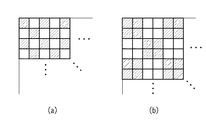
画像を自然画,文字,網点の3種類に大別した際、一般的に、自然画タイルにおいては画素値(この場合は輝度値)が平均値近傍に大きく分布しており、文字タイルに関しては、文字と背景とを比較した場合、背景の面積が文字の面積より大きいため、画素値分布は自然画ほどではないが、平均値近傍に分布する。ところが、網点の場合、図11(a)又は(b)から容易にわかる通り、画素値が平均近傍に分布しずらい。このため、分散を調べることで高い精度で網点の判定が可能となる。 When images are roughly classified into three types: natural images, characters, and halftone dots, pixel values (in this case, brightness values) are generally distributed near the average value in natural image tiles. When the character and the background are compared, the area of the background is larger than the area of the character, so the pixel value distribution is not as large as the natural image, but is distributed in the vicinity of the average value. However, in the case of halftone dots, the pixel values are difficult to be distributed in the vicinity of the average as can be easily seen from FIG. Therefore, the halftone dot can be determined with high accuracy by examining the dispersion.
分散算出部301は上記のようにして、注目タイルの分散を求め、注目タイルが網点領域にあるのか、非網点領域にあるのかを示す信号をセレクタ115に出力することになる。
The variance calculation unit 301 obtains the variance of the target tile as described above, and outputs a signal indicating whether the target tile is in the halftone dot region or the non-halftone dot region to the
次に、実施形態におけるセレクタ115の処理について説明する。このセレクタ115は、可逆符号化データ、非可逆符号化データのいずれか一方をタイル単位に選択し、それを注目タイルの符号化データとして出力するものである。
Next, processing of the
実施形態におけるセレクタ115の選択条件は次の通りである。なお、以下の説明で、CLKとは注目タイルの可逆符号化データ量(符号長)を示し、CLHとは注目タイルの非可逆符号化データ量を示すものとする。
条件1:注目タイルが網点領域であると判定された場合、有効レベル数カウント部104からの信号とは無関係に、可逆符号化データを選択し、出力する。
条件2:注目タイルが非網点領域であり、CLH<CLKの関係を満たす場合、非可逆符号化データを選択し、出力する。
条件3:注目タイルが非網点領域であり、CLH≧CLKの関係を満たす場合、可逆符号化データを選択し、出力する。
条件4:上記条件2、3において、注目タイルの全コンポーネントの有効レベル数NLV(c)が、閾値MLより小さい場合、注目タイルの符号化データとして可逆符号化データが選択され易いようにするため、CLHに所定の正の値を加算する。
The selection conditions of the
Condition 1: When it is determined that the target tile is a halftone dot region, lossless encoded data is selected and output regardless of the signal from the valid level
Condition 2: When the target tile is a non-halftone area and satisfies the relationship CLH <CLK, lossy encoded data is selected and output.
Condition 3: When the tile of interest is a non-halftone area and satisfies the relationship CLH ≧ CLK, lossless encoded data is selected and output.
Condition 4: When the effective level number NLV (c) of all the components of the target tile is smaller than the threshold value ML in the
次に、実施形態における符号列形成部116を説明する。符号列形成部116は、セレクタ115から出力されるタイルごとの符号化データを結合させて受け取り、入力画像全体に対応する符号列を形成して出力する。そのため、符号化データの先頭には、図9に示すように、画像を復号するために必要となる情報、例えば、画像の水平方向画素数、垂直方向画素数(タイルサイズは固定とするので、タイル数を示す情報でもある)、コンポーネント数、各コンポーネントのビット数などの付加情報がヘッダとして付けられる。
Next, the code
以上説明したように本実施形態によれば、網点領域以外の文字線画領域や自然画については、基本的に、符号量の少ない符号化データが選択されることになることになるので、画像全体の圧縮符号化効率は高いものとすることができる。そして、エッジが明瞭で、且つ、色数が少ない文字線画領域(例えば白地にエッジが明確な黒色の文字がある領域)には、可逆符号化データが選択される確率が高くなるので、文字線画のエッジが不鮮明になるのを抑制することができる。そして。網点領域については、可逆符号化データと非可逆符号化データが混在することを抑制でき、且つ、網点の性質が損なわることがない可逆符号化データのタイルで統一されるので、画質劣化を防ぐことが可能になる。 As described above, according to the present embodiment, encoded data with a small code amount is basically selected for a character / line image region or a natural image other than the halftone dot region. The overall compression encoding efficiency can be high. In a character / line drawing region with clear edges and a small number of colors (for example, a region where black characters with a clear edge are present on a white background), the probability of selecting lossless encoded data increases. It is possible to suppress the edge of the image from becoming unclear. And then. As for the halftone dot area, it is possible to suppress a mixture of lossless encoded data and lossy encoded data, and it is unified with tiles of lossless encoded data that do not impair the properties of the halftone dots, so image quality deterioration It becomes possible to prevent.
また、実施形態で説明したように、可逆符号化の場合、入力された各色成分値をそのまま利用した可逆符号化と、インデックス値による可逆符号化の2つが存在することにより、文字・線画領域では、そのほとんどがインデックス値に基づく符号化が採用されることになり、更に高い圧縮率が期待できる。 In addition, as described in the embodiment, in the case of lossless encoding, there are two types of lossless encoding using input color component values as they are and lossless encoding using index values. In most cases, encoding based on the index value is adopted, and a higher compression rate can be expected.
上記実施形態におけるセレクタ115の選択条件は、条件1乃至4に限るものではない。例えば、1タイルの許容符号化データ量MPRを定義し、可逆符号化データ量CLKとの関係が「CLK<MPR」を満たしていれば、符号量としては満足することが約束されているので、可逆符号化データを選択するようにしても良い。
The selection conditions of the
なお、実施形態における復号装置は、上記の符号化装置の説明から明らかであるが、例えば図12の構成で実現できよう。以下、同図に従って説明する。 Note that the decoding apparatus according to the embodiment is apparent from the above description of the encoding apparatus, but may be realized with the configuration of FIG. 12, for example. Hereinafter, description will be given with reference to FIG.
タイルヘッダ解析部1201はタイル単位に符号化データを入力し、各タイルのヘッダを解析する。そして、そのタイルの符号化データが可逆であると判断した場合には、可逆復号部1202に入力した符号化データを出力する。一方、非可逆符号化データであると判断した場合には、非可逆復号部1203に出力する。
A tile
この結果、いずれかの復号部でタイル画像にまで復号されるが、タイルヘッダ解析部1201は、復号処理を行わせた復号部からのデータを選択させる信号をセレクタ1204に出力する。セレクタ1204は、この選択信号に従って、復号データを選択し、それをタイルバッファ1205に出力する。ブロック合成部1206は、タイルバッファ1205に格納されたタイル画像を読出し、ストライプバッファ1207の該当する位置に書き込む。そして1ストライプ分の復号画像が得られたところで、ストライプバッファ1207を復号結果の出力先、例えば、プリンタ等に出力することを繰り返す。
As a result, even one of the decoding units decodes the tile image, but the tile
ここで可逆復号部1202は、例えば図13の構成で良いであろう。インデックス判定部は、符号化データのヘッダを解析し、インデックスの変換テーブル(図10(b)参照)があるか否かを判定し、変換テーブルが存在する場合には、その変換テーブル(符号化されている)を、インデックス復号部1202bに出力する。インデックス復号部1202bは、変換テーブルを復号し、インデックス値から画素値(実施形態では輝度値)への逆変換テーブルを生成し、それを逆インデックステーブルメモリ1202cに書き込む。この後、インデックス判定部1201は、各コンポーネントの符号化データを可逆復号部1202eに出力し、復号を行わせる。復号結果は、画素値、もしくは、インデックス値のいずれかとなる。逆インデックス変換部1202dは、復号されたデータをインデックス値であるものとし、逆インデックステーブル1202cを参照して画素値に変換する。インデックス判定部1202aは、各コンポーネントがインデックス値、画素値のいずれで符号化されているかについて判定済みであるので、その判定結果をセレクタ1202fに出力することで、注目タイルの注目コンポーネントの画素値を復号することが可能になる。
Here, the
<変形例の説明>
上記実施形態では図1の構成に基づく説明であったが、パーソナルコンピュータ等の汎用の情報処理装置(以下、PC)上で実行するコンピュータプログラムでもっても実現する例を以下に説明する。
<Description of modification>
Although the above embodiment has been described based on the configuration of FIG. 1, an example that can be realized even by a computer program executed on a general-purpose information processing apparatus (hereinafter, PC) such as a personal computer will be described below.
図14はPCのブロック構成図である。図示において、1401は装置全体を制御するCPUであり、1402はメインメモリとなるRAMである。1403はBIOSやブートプログラムを格納しているROMである。1404はキーボード、1405はマウス(登録商標)等のポインティングデバイス(PD)である。1406はCRTや液晶等の表示装置である。1407はハードディスク装置等の外部記憶装置であり、ここにOSをはじめ、画像圧縮に関するプログラムが格納されている。また、各種データファイルもここに格納される。1408はフロッピー(登録商標)ディスクドライブ、CD−ROMドライブ等の記憶媒体ドライブであり、1409はスキャナ装置等の外部装置と接続するためのインタフェースである。そして、1410は上記構成を電気的に接続するためのバスである。
FIG. 14 is a block diagram of the PC. In the figure, 1401 is a CPU for controlling the entire apparatus, and 1402 is a RAM serving as a main memory. A
上記構成において、本装置の電源をONにすると、CPU1401はROM1403に格納されたOSをRAM1402にロードし、起動することになる。OS起動後、本変形例における画像符号化アプリケーションプログラムをOSを介して外部記憶装置1407からRAM1402にロードし、実行する。
In the above configuration, when the power of this apparatus is turned on, the
ここでは説明を簡単なものとするため、インタフェース1409にイメージスキャナが接続されていて、原稿を読取り、その画像を符号化し、外部記憶装置1407にファイルとして格納する例を説明する。説明を簡単なものとするため、入力画像は上記の実施形態と同じ、R、G、B各8ビットで表わされているものとする。
In order to simplify the description, an example will be described in which an image scanner is connected to the
図15、図16は本変形例における符号化処理を示すフローチャートである。 15 and 16 are flowcharts showing the encoding process in this modification.
先ず、ステップS1201では、原稿画像を読取り、RAM1402に確保されたバッファーに1ストライプ分の画像データを格納する。
First, in step S1201, a document image is read, and image data for one stripe is stored in a buffer secured in the
そして、ステップS1202にて、1タイル分の画像データをバッファより読み出す。そして、ステップS1250で、フラグFLAGを“0”に初期化し、ステップS1202で、そのタイルの輝度成分の分散を算出し、そのタイルが網点領域中にあるか否かを判断する。網点領域中にあると判定した場合には、ステップS1251でフラグFLAGを“1”をセットし、ステップS1203を行わず、ステップS1204に進む。一方、網点領域以外であると判断した場合には、ステップS1203で非可逆符号化を行う(この非可逆符号化処理で得られた符号化データ量をCLHとする)。つまり、網点領域である場合には、この時点で注目タイルについては、可逆符号化を行うことが約束されるわけであるから、ステップS1203の処理をスキップしたことをフラグFLAGに記憶させることになる。従って、網点領域にある場合には、非可逆符号化処理が行われないことになるので、処理速度を早めることが可能になる。 In step S1202, image data for one tile is read from the buffer. In step S1250, the flag FLAG is initialized to “0”. In step S1202, the variance of the luminance component of the tile is calculated, and it is determined whether or not the tile is in the halftone area. If it is determined that the image is in the halftone dot region, the flag FLAG is set to “1” in step S1251, and the process proceeds to step S1204 without performing step S1203. On the other hand, if it is determined that the area is other than the halftone dot area, irreversible encoding is performed in step S1203 (the encoded data amount obtained by this irreversible encoding process is defined as CLH). In other words, in the case of the halftone dot region, it is promised that lossless encoding is performed for the target tile at this time, and therefore it is stored in the flag FLAG that the processing in step S1203 has been skipped. Become. Therefore, in the case of the halftone dot region, the lossy encoding process is not performed, so that the processing speed can be increased.
さて、処理がステップS1204に進むと、可逆符号化の前段階である、読出した1タイル中のR、G、Bの有効レベル数NLV(R)、NLV(G)、NLV(B)を算出する。この処理は、図6に示すフローチャートにしたがえば良いであろう。 When the process proceeds to step S1204, the effective level numbers NLV (R), NLV (G), and NLV (B) of R, G, and B in one read tile, which is the previous stage of lossless encoding, are calculated. To do. This processing may be performed according to the flowchart shown in FIG.
そして、ステップS1205にて、R成分の有効レベル数NLV(R)と閾値MLとを比較し、「NLV(R)≧ML」の関係を満たす場合には、ステップS1206に進んで、入力したタイルのR成分値をそのまま利用して可逆符号化を行う。 In step S1205, the effective level number NLV (R) of the R component is compared with the threshold value ML. If the relationship of “NLV (R) ≧ ML” is satisfied, the process proceeds to step S1206, and the input tile The lossless encoding is performed by using the R component value of.
また、「NLV(R)<ML」の関係にあると判断した場合には、ステップS1207にてインデックス化し、ステップS1208にてインデックス値を可逆符号化する。 If it is determined that “NLV (R) <ML”, the index value is indexed in step S1207 and the index value is losslessly encoded in step S1208.
上記はR成分についての可逆符号化処理であるが、上記と同様の処理を、G、B成分についても行う。これを示すのがステップS1209、S1210である。それぞれの処理内容は、NLV(G)、NLV(B)と置換えれば良いので説明するまでもないであろう。 The above is the lossless encoding process for the R component, but the same process as described above is also performed for the G and B components. This is shown in steps S1209 and S1210. Each processing content may be replaced with NLV (G) and NLV (B), and will not be described.
1つのタイルに対するR、G、Bの全コンポーネントの可逆符号化処理が完了する(生成される符号化データ量をCLKとする)と、ステップS1252にて、フラグFLAGが“1”であるか否かを判断する。“1”である場合には、注目タイルについては可逆符号化データを出力されることになっているので、ステップS1215(後述)に処理を進む。 When the lossless encoding processing of all the R, G, and B components for one tile is completed (the amount of encoded data to be generated is CLK), whether or not the flag FLAG is “1” in step S1252. Determine whether. In the case of “1”, lossless encoded data is to be output for the tile of interest, so the process proceeds to step S1215 (described later).
また、フラグFLAGが“1”ではなく“0”であると判断した場合には、ステップS1211にて、全有効レベル数NLV(R)、NLV(G)、NLV(B)が閾値ML未満であるか否かを判断する。もしこの条件を満たすと判断した場合には、ステップS1212にて重み付け係数αに正の所定値(実施形態では仮に“100”)を設定する。また、1つの色成分の有効レベル数が閾値ML以上になった場合には、重み付け係数αには“0”を設定する。 If it is determined that the flag FLAG is not “1” but “0”, in step S1211, the total number of effective levels NLV (R), NLV (G), and NLV (B) are less than the threshold ML. Judge whether there is. If it is determined that this condition is satisfied, a positive predetermined value (temporarily “100” in the embodiment) is set to the weighting coefficient α in step S1212. When the number of effective levels of one color component is equal to or greater than the threshold ML, “0” is set to the weighting coefficient α.
こうして、重み付け係数αの設定処理を終えると、処理はステップS1214に進み、「CLK<CLH+α」を満足するか否かを判定する。 Thus, when the setting process of the weighting coefficient α is completed, the process proceeds to step S1214 to determine whether or not “CLK <CLH + α” is satisfied.
「CLK<CLH+α」を満たすと判断した場合、或いは、ステップS1252でYesと判定された場合、先のステップS1205乃至S1210で得られた可逆符号化データを、注目タイルの符号化データとしてRAM1402に確保された出力バッファに出力する。この際、データフォーマットは図10(a)もしくは図10(b)の形式である。
When it is determined that “CLK <CLH + α” is satisfied, or when it is determined Yes in step S1252, the lossless encoded data obtained in the previous steps S1205 to S1210 is secured in the
また、「CLK≧CLH+α」と判断した場合には、先のステップS1203の処理で得られた非可逆符号化データを、注目タイルの符号化データとして出力バッファに出力する。 If it is determined that “CLK ≧ CLH + α”, the lossy encoded data obtained in the process of step S1203 is output to the output buffer as encoded data of the target tile.
ステップS1217は、注目タイルが注目ストライプの最後のタイルであるか否かを判断する。否の場合には、ステップS1202以降の処理を繰り返す。 In step S1217, it is determined whether the target tile is the last tile of the target stripe. If not, the processes after step S1202 are repeated.
また、注目タイルが注目ストライプの最後のタイルであると判断した場合には、ステップS1218に進み、注目ストライプが画像データの最終ストライプであるか否かを判断し、否の場合にはステップS1201以降の処理を繰り返す。 If it is determined that the tile of interest is the last tile of the stripe of interest, the process advances to step S1218 to determine whether or not the stripe of interest is the final stripe of the image data. Repeat the process.
最終ストライプの最終タイルであった場合、画像全体の符号化が完了したことを意味するので、ステップS1219に進み、ヘッダ情報を付加し、出力バッファに格納された符号化データをファイルとして外部記憶装置1407に書き込み保存し、本処理を終了することになる。 If it is the final tile of the final stripe, it means that the encoding of the entire image has been completed, and the process advances to step S1219 to add header information and use the encoded data stored in the output buffer as a file as an external storage device. The information is written and saved in 1407, and this processing is terminated.
以上説明したように、先に説明した第1の実施形態と同様の処理を、PC等の汎用の情報処理装置上で実行するアプリケーションプログラムとしても実現できることになり、同様の作用効果を奏することが可能になる。 As described above, the same processing as that of the first embodiment described above can be realized as an application program executed on a general-purpose information processing device such as a PC, and the same operational effects can be achieved. It becomes possible.
なお、復号処理であるが、復号処理は基本的に符号化処理とは逆の手順にしたがって行えばよいのは、自明のことであろうから、ここでの説明については省略する。 It should be noted that although it is a decoding process, it is obvious that the decoding process basically needs to be performed in accordance with the reverse procedure of the encoding process, and therefore description thereof is omitted here.
また、実施形態では、符号化対象の画像データはR、G、B成分で表現され、各8ビットであるものとして説明したが、これに限られるものではなく、他の色空間、他のビット数でも構わない。これは以下に説明する例でも同様である。 In the embodiment, the image data to be encoded is expressed as R, G, and B components, each having 8 bits. However, the present invention is not limited to this, and other color spaces and other bits are used. It can be a number. The same applies to the examples described below.
[第2の実施形態]
上記第1の実施形態、並びにその変形例では、着目するタイルの有効レベル数に応じて符号化処理(または符号化データ)の選択の際に加算する重み付け係数を求めるものであった。
[Second Embodiment]
In the first embodiment and its modification, the weighting coefficient to be added when selecting the encoding process (or encoded data) is obtained according to the number of effective levels of the tile of interest.
しかし、上記の処理によって本願発明が限定されるものではない。例えば、2つの符号化データの一方を選択され易いようにするためには、一方に重み付け係数を加算すること以外に、減算する手法を採用しても構わないし、乗算、除算を採用しても構わない。 However, the present invention is not limited by the above processing. For example, in order to make it easy to select one of the two encoded data, a method of subtracting may be adopted in addition to adding a weighting coefficient to one of the two encoded data, or multiplication and division may be adopted. I do not care.
例えば、乗算を利用するのであれば、ステップS1212にてαに“1.1”を設定し、ステップS1213ではαに“1.0”を設定する。そして、ステップS1214では、「CLK<CLH×α」を満たすか否かを判断すれば良い。 For example, if multiplication is used, “1.1” is set to α in step S1212, and “1.0” is set to α in step S1213. In step S1214, it may be determined whether or not “CLK <CLH × α” is satisfied.
[第3の実施形態]
上記実施形態では、タイルの輝度の分散を求めることで、タイルが網点属性を有するか否かを判定したが、注目タイル中に、図11(a)、(b)に示すように1×1の画素ドット、2×2の画素ドットが所定数存在する場合に、注目タイルを網点領域と判定するようにしても良い。このためには、注目タイルのRGB成分値から輝度成分値のみを得、その後、その輝度値を閾値(=128で良いであろう)で単純2値化し、その結果、1×1〜2×2の孤立画素群のタイルの面積に湿る割合が所定以上であるか否かで、網点の属性を有するか否かを判定しても構わない。
[Third Embodiment]
In the above embodiment, it is determined whether or not the tile has a halftone dot attribute by obtaining the distribution of the luminance of the tile. However, in the tile of interest, as shown in FIGS. 11A and 11B, 1 × When a predetermined number of 1 pixel dot and 2 × 2 pixel dots exist, the target tile may be determined as a halftone dot region. For this purpose, only the luminance component value is obtained from the RGB component values of the tile of interest, and then the luminance value is simply binarized with a threshold value (= 128 may be acceptable). As a result, 1 × 1-2 × Whether or not the image has a halftone dot attribute may be determined based on whether the ratio of the wetness to the tile area of the two isolated pixel groups is greater than or equal to a predetermined value.
以上、第1乃至第3の実施形態について説明したが、第1の実施形態の変形例で説明したように、本発明はコンピュータプログラムによっても実現できるのは明らかである。 Although the first to third embodiments have been described above, as described in the modification of the first embodiment, it is obvious that the present invention can be realized by a computer program.
また、実施形態では説明したように、基本的には、可逆符号化データ量と非可逆符号化データ量の少ない方を選択するものであるので、文字線画についてはそのエッジが保存されるように可逆符号化を用い、自然画については階調性が保存するのに都合の良い非可逆符号化が選択されることが望ましい。かかる点から、可逆符号化としてはJPEG−LS、非可逆符号化としてはJPEGを用いることが好適である。 In addition, as described in the embodiment, basically, the smaller one of the lossless encoded data amount and the lossy encoded data amount is selected, so that the edge of the character / line image is stored. It is desirable to use lossless encoding and to select lossy encoding that is convenient for preserving gradation for natural images. From this point, it is preferable to use JPEG-LS as lossless encoding and JPEG as lossy encoding.
また、PC等からデータが送信されてきた際、所定の領域毎に属性情報が送信されてくることもある。その属性情報から網点領域を識別し、その上で網点領域を強制的に可逆変換を選択する方法も本発明の範疇に入る。 Further, when data is transmitted from a PC or the like, attribute information may be transmitted for each predetermined area. A method of identifying a halftone area from the attribute information and forcibly selecting a reversible transformation on the halftone area is also included in the scope of the present invention.
更に、符号量比較により可逆符号化方式と非可逆符号化方式を選択する際、符号量に重み付けする方法を示しているが、重み付けを行わない方法も本発明の範疇に入る。 Furthermore, although a method of weighting the code amount when selecting the lossless encoding method and the lossy encoding method by code amount comparison is shown, a method without weighting also falls within the scope of the present invention.
また、通常、コンピュータプログラムは、それを格納したCD−ROM等のコンピュータ可読記憶媒体を、コンピュータにセットし、システムにコピーもしくはインストールすることで実行可能になるわけであるから、当然、このようなコンピュータ可読記憶媒体も本願発明の範疇にあることも明らかである。 Moreover, since a computer program is normally executable by setting a computer-readable storage medium such as a CD-ROM storing the computer program in a computer and copying or installing the computer program in a system, naturally It is also clear that computer-readable storage media are within the scope of the present invention.
Claims (7)
画像データを所定サイズのブロックに分割する分割手段と、
分割されたブロックが網点画像の属性を有する否かを判定する判定手段と、
分割されたブロックについて可逆符号化し、可逆符号化データを生成する可逆符号化手段と、
分割されたブロックについて非可逆符号化し、非可逆符号化データを生成する非可逆符号化手段と、
前記判定手段によって、注目ブロックが網点画像の属性を有すると判定された場合、前記可逆符号化手段で生成された可逆符号化データを選択し、注目ブロックが網点画像の属性を有さないと判定された場合には、前記可逆符号化手段及び前記非可逆符号化手段それぞれで生成された符号化データのデータ量を重み付け比較し、データ量の少ない符号化データを選択し、出力する選択手段と、
前記選択手段で選択されたブロック毎の符号化データを結合して、所定の符号化データ列として出力する出力手段と
を備えることを特徴とする画像符号化装置。 An image encoding device for inputting and encoding image data,
A dividing means for dividing the image data into blocks of a predetermined size;
Determining means for determining whether or not the divided block has the attribute of a halftone image;
A lossless encoding means for performing lossless encoding on the divided blocks and generating lossless encoded data;
Irreversible encoding means for irreversibly encoding the divided blocks and generating irreversible encoded data;
By the determination unit, the block of interest when it is determined to have attributes of halftone image, select lossless encoded data generated by the reversible coding means, the block of interest does not have the attributes of the halftone image If it is determined that the data amount of the encoded data generated by each of the lossless encoding unit and the lossy encoding unit is weighted and compared, the encoded data with a small amount of data is selected and output is selected. Means,
An image encoding apparatus comprising: output means for combining encoded data for each block selected by the selection means and outputting the result as a predetermined encoded data string.
前記分割手段で分割されたブロック中の各色成分の取り得る成分値範囲で、幾つの成分値が存在したかを示す出現数を計数する計数手段と、
ブロック内の各色成分値をインデックス値に変換する変換手段と、
該計数手段で得られた各色成分の出現数と所定の閾値とを比較する比較手段と、
該比較手段の比較結果が前記出現数が前記閾値未満であることを示す場合には、前記変換手段で変換されたインデックス値を可逆符号化し、閾値以上であることを示す場合には成分値を可逆符号化する手段と
を備えることを特徴とする請求項1に記載の画像符号化装置。 The lossless encoding means includes
In the possible component value ranges of the color components in the block where the divided by dividing means, counting means for counting the number of occurrences indicating how many component value exists,
Conversion means for converting each color component value in the block into an index value;
Comparison means for comparing the number of appearance of each color component obtained by the counting means with a predetermined threshold;
When the comparison result of said comparing means indicates that the number of occurrences is less than the threshold value, and lossless encoding the transformed index value by the conversion means, the component value to indicate that it is equal to or larger than the threshold value The image encoding apparatus according to claim 1, further comprising: a lossless encoding unit.
条件:CLK<CLH+α
を満足する場合には、前記可逆符号化手段で得られた可逆符号化データを選択し、前記条件を満たさない場合には前記非可逆符号化手段で得られた非可逆符号化データを選択することを特徴とする請求項2に記載の画像符号化装置。 Weighting the comparison in the selection means, a code amount obtained by the reversible coding means CLK, lossy encoding CLH code amount obtained by unit, the number of occurrences of all the color components of the target block is less than a predetermined If the weighting factor α is defined as a positive predetermined value in some cases and 0 otherwise,
Condition: CLK <CLH + α
When satisfied, select the lossless encoded data obtained by the reversible coding means, if does not satisfy the conditions are selected lossy encoded data obtained by the non-reversible coding means The image coding apparatus according to claim 2, wherein:
画像データを所定サイズのブロックに分割する分割工程と、
分割されたブロックが網点画像の属性を有する否かを判定する判定工程と、
分割されたブロックについて可逆符号化し、可逆符号化データを生成する可逆符号化工程と、
分割されたブロックについて非可逆符号化し、非可逆符号化データを生成する非可逆符号化工程と、
前記判定工程によって、注目ブロックが網点画像の属性を有すると判定された場合、前記可逆符号化工程で生成された可逆符号化データを選択し、注目ブロックが網点画像の属性を有さないと判定された場合には、前記可逆符号化工程及び前記非可逆符号化工程それぞれで生成された符号化データのデータ量を重み付け比較し、データ量の少ない符号化データを選択し、出力する選択工程と、
前記選択工程で選択されたブロック毎の符号化データを結合して、所定の符号化データ列として出力する出力工程と
を備えることを特徴とする画像符号化方法。 An image encoding method for inputting and encoding image data,
A dividing step of dividing the image data into blocks of a predetermined size;
A determination step of determining whether or not the divided block has an attribute of a halftone image;
A lossless encoding step for lossless encoding of the divided blocks and generating lossless encoded data;
An irreversible encoding step of irreversibly encoding the divided blocks and generating irreversible encoded data;
By the determination step, when the block of interest is determined to have attributes of halftone image, select lossless encoded data generated by the reversible encoding process, the block of interest does not have the attributes of the halftone image When it is determined that the data amount of the encoded data generated in each of the lossless encoding step and the lossy encoding step is weighted and compared, the encoded data with a small amount of data is selected and output is selected. Process,
An image encoding method comprising: an output step of combining the encoded data for each block selected in the selection step and outputting as a predetermined encoded data string.
画像データを所定サイズのブロックに分割する分割手段と、
分割されたブロックが網点画像の属性を有する否かを判定する判定手段と、
分割されたブロックについて可逆符号化し、可逆符号化データを生成する可逆符号化手段と、
分割されたブロックについて非可逆符号化し、非可逆符号化データを生成する非可逆符号化手段と、
前記判定手段によって、注目ブロックが網点画像の属性を有すると判定された場合、前記可逆符号化手段で生成された可逆符号化データを選択し、注目ブロックが網点画像の属性を有さないと判定された場合には、前記可逆符号化手段及び前記非可逆符号化手段それぞれで生成された符号化データのデータ量を重み付け比較し、データ量の少ない符号化データを選択し、出力する選択手段と、
前記選択手段で選択されたブロック毎の符号化データを結合して、所定の符号化データ列として出力する出力手段
として機能させることを特徴とするコンピュータプログラム。 By computer executes read, the computer, the image data input to a computer program that causes functions as an image encoding device for encoding,
A dividing means for dividing the image data into blocks of a predetermined size;
Determining means for determining whether or not the divided block has the attribute of a halftone image;
A lossless encoding means for performing lossless encoding on the divided blocks and generating lossless encoded data;
Irreversible encoding means for irreversibly encoding the divided blocks and generating irreversible encoded data;
By the determination unit, the block of interest when it is determined to have attributes of halftone image, select lossless encoded data generated by the reversible coding means, the block of interest does not have the attributes of the halftone image If it is determined that the data amount of the encoded data generated by each of the lossless encoding unit and the lossy encoding unit is weighted and compared, the encoded data with a small amount of data is selected and output is selected. Means,
A computer program which functions as output means for combining encoded data for each block selected by the selection means and outputting the result as a predetermined encoded data string.
Priority Applications (1)
| Application Number | Priority Date | Filing Date | Title |
|---|---|---|---|
| JP2004331106A JP4324079B2 (en) | 2004-11-15 | 2004-11-15 | Image encoding apparatus and method, computer program, and computer-readable storage medium |
Applications Claiming Priority (1)
| Application Number | Priority Date | Filing Date | Title |
|---|---|---|---|
| JP2004331106A JP4324079B2 (en) | 2004-11-15 | 2004-11-15 | Image encoding apparatus and method, computer program, and computer-readable storage medium |
Publications (3)
| Publication Number | Publication Date |
|---|---|
| JP2006140968A JP2006140968A (en) | 2006-06-01 |
| JP2006140968A5 JP2006140968A5 (en) | 2007-12-27 |
| JP4324079B2 true JP4324079B2 (en) | 2009-09-02 |
Family
ID=36621426
Family Applications (1)
| Application Number | Title | Priority Date | Filing Date |
|---|---|---|---|
| JP2004331106A Expired - Fee Related JP4324079B2 (en) | 2004-11-15 | 2004-11-15 | Image encoding apparatus and method, computer program, and computer-readable storage medium |
Country Status (1)
| Country | Link |
|---|---|
| JP (1) | JP4324079B2 (en) |
Families Citing this family (3)
| Publication number | Priority date | Publication date | Assignee | Title |
|---|---|---|---|---|
| JP4952685B2 (en) * | 2008-08-26 | 2012-06-13 | 株式会社Jvcケンウッド | Video signal encoding device |
| EP2670139A1 (en) | 2012-06-01 | 2013-12-04 | Alcatel Lucent | Method and apparatus for encoding a video stream having a transparency information channel |
| CN113256744B (en) * | 2020-02-10 | 2023-03-24 | 武汉Tcl集团工业研究院有限公司 | Image coding and decoding method and system |
-
2004
- 2004-11-15 JP JP2004331106A patent/JP4324079B2/en not_active Expired - Fee Related
Also Published As
| Publication number | Publication date |
|---|---|
| JP2006140968A (en) | 2006-06-01 |
Similar Documents
| Publication | Publication Date | Title |
|---|---|---|
| JP4418762B2 (en) | Image encoding apparatus, image decoding apparatus, control method thereof, computer program, and computer-readable storage medium | |
| JP4979323B2 (en) | Image processing apparatus and control method thereof | |
| US7912300B2 (en) | Image processing apparatus and control method therefor | |
| US6320981B1 (en) | Image processing system and image processing method | |
| JP4847398B2 (en) | Image processing apparatus and method | |
| US8213727B2 (en) | Image encoding apparatus and image decoding apparatus, and control method thereof | |
| US8275210B2 (en) | Lossless compressor for image data values | |
| US20060044636A1 (en) | Image processing apparatus, image processing method, program, and storage medium | |
| JP2010103681A (en) | Image processing device and method | |
| JP2000050268A (en) | Image coding device | |
| JP2008042688A (en) | Image processing apparatus and control method thereof, and computer program and computer readable storage medium | |
| GB2345401A (en) | Compression of digital images comprising background pixels | |
| JP5116650B2 (en) | Image coding apparatus and control method thereof | |
| JP4324079B2 (en) | Image encoding apparatus and method, computer program, and computer-readable storage medium | |
| JP2008109478A (en) | Image encoding device, method, program and storage medium | |
| JP4084802B2 (en) | Image processing device | |
| JP2006080793A (en) | Image coder, method, compputer program, and computer readable storage medium | |
| JP2008042683A (en) | Image processing apparatus and its control method, computer program and computer readable storage medium | |
| JP4418736B2 (en) | Image encoding apparatus and method, computer program, and computer-readable storage medium | |
| JP4377351B2 (en) | Data compression apparatus and data compression program | |
| JP4771541B2 (en) | Image encoding apparatus and method, computer program, and computer-readable storage medium | |
| JP4743884B2 (en) | Image coding apparatus and control method thereof | |
| JP4795160B2 (en) | Image processing apparatus, control method therefor, computer program, and computer-readable storage medium | |
| JP4131969B2 (en) | Data compression apparatus and data compression program | |
| JP4377352B2 (en) | Data compression apparatus and data compression program |
Legal Events
| Date | Code | Title | Description |
|---|---|---|---|
| A521 | Written amendment |
Free format text: JAPANESE INTERMEDIATE CODE: A523 Effective date: 20071108 |
|
| A621 | Written request for application examination |
Free format text: JAPANESE INTERMEDIATE CODE: A621 Effective date: 20071108 |
|
| RD03 | Notification of appointment of power of attorney |
Free format text: JAPANESE INTERMEDIATE CODE: A7423 Effective date: 20071108 |
|
| TRDD | Decision of grant or rejection written | ||
| A01 | Written decision to grant a patent or to grant a registration (utility model) |
Free format text: JAPANESE INTERMEDIATE CODE: A01 Effective date: 20090525 |
|
| A01 | Written decision to grant a patent or to grant a registration (utility model) |
Free format text: JAPANESE INTERMEDIATE CODE: A01 |
|
| A61 | First payment of annual fees (during grant procedure) |
Free format text: JAPANESE INTERMEDIATE CODE: A61 Effective date: 20090605 |
|
| R150 | Certificate of patent or registration of utility model |
Ref document number: 4324079 Country of ref document: JP Free format text: JAPANESE INTERMEDIATE CODE: R150 Free format text: JAPANESE INTERMEDIATE CODE: R150 |
|
| FPAY | Renewal fee payment (event date is renewal date of database) |
Free format text: PAYMENT UNTIL: 20120612 Year of fee payment: 3 |
|
| FPAY | Renewal fee payment (event date is renewal date of database) |
Free format text: PAYMENT UNTIL: 20120612 Year of fee payment: 3 |
|
| FPAY | Renewal fee payment (event date is renewal date of database) |
Free format text: PAYMENT UNTIL: 20130612 Year of fee payment: 4 |
|
| LAPS | Cancellation because of no payment of annual fees |