JP4323864B2 - Method and system for generating calibration data for a digital camera - Google Patents
Method and system for generating calibration data for a digital camera Download PDFInfo
- Publication number
- JP4323864B2 JP4323864B2 JP2003144823A JP2003144823A JP4323864B2 JP 4323864 B2 JP4323864 B2 JP 4323864B2 JP 2003144823 A JP2003144823 A JP 2003144823A JP 2003144823 A JP2003144823 A JP 2003144823A JP 4323864 B2 JP4323864 B2 JP 4323864B2
- Authority
- JP
- Japan
- Prior art keywords
- block
- color
- data
- array
- camera
- Prior art date
- Legal status (The legal status is an assumption and is not a legal conclusion. Google has not performed a legal analysis and makes no representation as to the accuracy of the status listed.)
- Expired - Fee Related
Links
Images


Classifications
-
- H—ELECTRICITY
- H04—ELECTRIC COMMUNICATION TECHNIQUE
- H04N—PICTORIAL COMMUNICATION, e.g. TELEVISION
- H04N17/00—Diagnosis, testing or measuring for television systems or their details
- H04N17/002—Diagnosis, testing or measuring for television systems or their details for television cameras
-
- H—ELECTRICITY
- H04—ELECTRIC COMMUNICATION TECHNIQUE
- H04N—PICTORIAL COMMUNICATION, e.g. TELEVISION
- H04N23/00—Cameras or camera modules comprising electronic image sensors; Control thereof
- H04N23/80—Camera processing pipelines; Components thereof
- H04N23/81—Camera processing pipelines; Components thereof for suppressing or minimising disturbance in the image signal generation
-
- H—ELECTRICITY
- H04—ELECTRIC COMMUNICATION TECHNIQUE
- H04N—PICTORIAL COMMUNICATION, e.g. TELEVISION
- H04N17/00—Diagnosis, testing or measuring for television systems or their details
- H04N17/02—Diagnosis, testing or measuring for television systems or their details for colour television signals
Landscapes
- Engineering & Computer Science (AREA)
- Multimedia (AREA)
- Signal Processing (AREA)
- Health & Medical Sciences (AREA)
- Biomedical Technology (AREA)
- General Health & Medical Sciences (AREA)
- Color Television Image Signal Generators (AREA)
- Studio Devices (AREA)
Description
【0001】
【発明の属する技術分野】
本発明は、概してデジタル写真術に関し、特にデジタルカメラで使用する較正データの生成に関する。
【0002】
【従来の技術】
色に依存しない周辺光量低下は、カメラによって撮影された写真が、存在する色に係りなく中心から隅に向かって暗化を示す写真現象である。フィルムカメラで撮られた写真もデジタルカメラで撮られた写真もともに、周辺光量低下を示す可能性がある。ある程度の量の周辺光量低下は許容可能であり、実際には美術的な意味からは望ましい。しかしながら、過度な量の周辺光量低下は、大抵の人にとっては好ましくないものである。
【0003】
フィルムカメラかまたはデジタルカメラのいずれにおいても、かかる周辺光量低下は、画像を小さい平面、すなわちフィルムまたは光電変換イメージャ、たとえばCCD上に画像を取込まなければならないことによってもたらされる。いずれのタイプのカメラにおいても、フィルム/イメージャの隅に当る光線は、フィルム/イメージャの中心に直接入射する光線より長い経路を移動し、中心に入射する光とは異なる入射角で到達する。
【0004】
直接(直角に)入射する光とある角度をもって入射する光とに対するフィルム/イメージャの応答の差により、取込画像に不均一性がもたらされ、そのうちのいくつかが周辺光量低下とみなされる。さらに、レンズ系がまた周辺光量低下をもたらす。その上、カメラがフラッシュ装置を使用する場合、フラッシュ装置の被写体面上での照度変化も周辺光量低下の要因となる。
【0005】
デジタルカメラの画像センサは、色に依存する周辺光量低下も同様にもたらす。デジタルカメラにおける通常のカラー画像センサは、モザイクタイプの画像センサ、たとえばCCDを含み、その上に、赤、緑および青色を含むフィルタアレイが形成される。各ピクセルは、対応する赤、緑または青フィルタ領域を有する。カラーフィルタの通常の実施態様は、2ラインパターンを繰り返す。第1ラインは、赤および緑ピクセルが交互に繰り返されたものを含み、第2ラインは、青および緑ピクセルが交互に繰り返されたものを含む。緑ピクセルの数を多くするのは、人間の眼が緑の光に対して比較的高い感度を有していることに対応するためである。そして、センサによって形成されるデータ画像の各色ごとのカラーアレイが組合されることにより、適当な処理の後にフルカラー画像が生成される。
【0006】
【発明が解決しようとする課題】
色に依存する周辺光量低下は、画像センサによって取込まれた画像に示される画像の中心から隅への感色性変化として理解されなければならない。これは、通常の色に依存しない周辺光量低下に加えて存在する。人間の眼は、色に依存する変化に非常に敏感である。このため、色に依存する周辺光量低下は、わずかな量でも非常に不快である。
【0007】
色に依存する周辺光量低下を、より高品質のレンズ系、画像センサおよび/またはフラッシュ装置を使用することによって最小化することができる。しかしながら、これは、システムコストおよび/またはシステム複雑性の最小化が重要な設計基準である状況では実際的でない解決法である。
【0008】
本発明の目的は、デジタルカメラのための較正データを生成する方法(および対応する装置)を提供することである。
【0009】
【課題を解決するための手段】
本発明は、その1つとして、デジタルカメラのための較正データを生成する方法(および対応する装置)を提供する。かかる方法は、カメラの前に、撮影対象の基準面を配置することと、カメラを介して、カメラが撮影することができる、各色における基準面の画像に対応するデータの特性アレイを取込むこととを含む。
【0010】
かかるテクノロジは、方法のみでなく対応するシステムおよびコンピュータ読取可能媒体(プロセッサによる実行時にプロセッサに対し本方法を実行させるコード部分を有する)もまた含む。
【0011】
本発明のさらなる特徴および利点は、例示的な実施形態の以下の詳細な説明と、併記の特許請求の範囲と、添付図面とからより完全に明らかとなろう。
【0012】
【発明の実施の形態】
本発明の実施形態は、一部には、生(処理前の)デジタル画像をデジタル処理することにより、周辺光量低下、たとえば色に依存する周辺光量低下に関してデジタル画像の品質を向上させることができる、という認識である。
【0013】
同様に、本発明の実施形態は、一部には、デジタル画像のデジタル補正が、所望のシーンの生データを補正するために使用することができる基準データまたは補正データに基づくことができる、という認識である。
【0014】
また、同様に、本発明の実施形態は、一部には、かかる較正データを生成するテクノロジを提供する。
【0015】
本発明の実施形態は同様に、一部には、カメラ動作パラメータ、たとえば口径およびズームの多くのあり得る組合せのうちのいくつかに対応して、赤、青および緑の特性アレイのセットを何セットか取込んだ場合に、非常に優れた色依存補正結果を得ることができる、という認識である。
【0016】
本発明の実施形態は同様に、一部には、(特性アレイの)較正セットによって表されるデータの量が、画像を表すデータの量と比較して低減されると、優れた色依存補正結果を取得することができる、という認識である。
【0017】
図1は、本発明の実施形態によるデジタルカメラのハードウェアアーキテクチャの概略ブロック図である。図1のデジタルカメラ100は、A/D変換器104にアナログ信号を供給するCCD102を含み、A/D変換器104は、ASIC106にデジタル化されたCCD102の出力を供給する。ASIC106は、CCD102を動作させるために使用されるクロックドライバ108にクロック信号を供給する。
【0018】
また、カメラ100は、ASIC106によってモータドライバ112を介して作動されるズーム(オプション)、焦点調節、絞りおよびシャッタ機構110と、ASIC106によって制御されるストロボドライブ116を介して作動されるストロボユニット114とを含む。メモリデバイスに関し、デジタルカメラ100は、揮発性メモリ、すなわちSDRAMデバイス118と、不揮発性メモリ、すなわち内部フラッシュメモリデバイス120と、さらに、外部コンパクトフラッシュ(登録商標)メモリデバイスに接続するためのコネクタ122を含む。ASIC106はまた、USBコネクタ126を介して、外部ワークステーション124にも接続することができる。
【0019】
また、デジタルカメラ100は、ASIC106が通信することを可能にするマイクロコントローラ128も含む。
【0020】
カメラの他のアーキテクチャが考えられる。かかるアーキテクチャの各々は、1つまたは複数のプロセッサと、1つまたは複数の揮発性メモリデバイスと、1つまたは複数の不揮発性メモリデバイスとを含むことができる。
【0021】
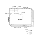
図2は、画像形成されたシーンの各々に対しカメラ100が生成する3つのカラープレーンすなわちカラーアレイ(202R、202Gおよび202B)を象徴的に示す。通常、3つのカラーアレイを以下のように生成することができる。カメラ100は、実際には、第1ラインがRGRGRG…であり第2ラインがGBGBGB…であるモザイク画像(図示せず)を生成する。ラインパターンは、2ライン毎に繰り返す。3つのアレイを得るために、モザイク状の画像は2×2のブロックに分離される。これらのブロックの各々から、2つの緑が平均化され赤ピクセルおよび青ピクセルはそのまま取出される。これにより、画像センサのフル解像度の1/4の解像度を有する3つのカラーアレイが生成される。後で説明するが、各カラーアレイ(202R、202Gおよび202B)を同じサイズのブロック206で分割することができる。また、各カラーアレイは中心領域204を有する。
【0022】
CCD102は、複雑および/または高性能でないほど、色に依存する周辺光量低下を受け易くなる。色に依存する周辺光量低下の程度を測定する技法は、一様に照明された白色ターゲットを、デジタルカメラを用いて撮影し、その後各カラーアレイを別々に評価する、というものである。評価は、X軸およびY軸が、画像を形成するピクセルの列の値および行の値に対応する等高線図の形態をとることができる。図3A、図3Bおよび図3Cは、あるカメラパラメータ(たとえば、ズーム、開口、シャッタスピード等)の組合せに対応する、赤アレイ、緑アレイおよび青アレイそれぞれの等高線図例を示す。各図の右側のグレースケールは、−20%から+20%まで変化する、対応する等高線中に見える濃淡の範囲を説明する凡例である。言換えれば、等高線は、2%の間隔で濃淡強度の差を示している。
【0023】
図3A、図3Bおよび図3Cから、ピクセル強度、すなわち各ピクセルにおけるCCD102の赤、緑および青の光に対する感度が、一様に照明された白色ターゲットの画像に対して変化しているため、例示したカメラが色に依存しない周辺光量低下を示す、ということが分かる。色に依存しない周辺光量低下が示されなかった場合、CCD102のすべてのピクセル位置におけるすべてのピクセルの強度が画像の中心の値と等しい筈である。
【0024】
図3A、図3Bおよび図3Cをさらに調べることにより、各々が異なることも分かる。したがって、図3A、図3Bおよび図3Cを見比べることにより、カメラ100が色に依存する周辺光量低下を生じていることもわかる。言換えれば、図3A、図3Bおよび図3Cの各々がみな同じであった場合、カメラ100は、色に依存する周辺光量低下を示さないことになる。
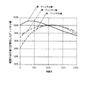
【0025】
図4は、図3A、図3Bおよび図3Cの実施例の各々からのピクセル配列中の同じ任意の行、たとえば第800行の並びに対応して、列番号に対してプロットされた赤ピクセル値、緑ピクセル値および青ピクセル値のグラフを示す。カメラ100が色に依存しない周辺光量低下を有していない場合、図4は、3つの水平線のプロットになる。加えて、カメラ100が色に依存する周辺光量低下を示した場合、3つの線は別々になる。しかしながら、色に依存する周辺光量低下もなかった場合、3つの水平線は重なり合い、図の上には1つの水平線しか見えないことになる。
【0026】
カメラが色に依存しない周辺光量低下を示す状況では、図4の状況のようにプロットは何らかの曲線となる。カメラが色に依存する周辺光量低下を示さない(しかしながら、色に依存しない周辺光量低下は示す)場合、3つの曲線は同一であって重なり合うことにより、実際には図の上に1つの曲線しか見えなくなる。カメラが色に依存しない周辺光量低下とともに色に依存する周辺光量低下の両方を示す場合、結果は、図4プロットされたようになる。
【0027】
図4において、各ピクセル値の大きさは、その中心ピクセルの値に関して規格化されている。すなわち、各ピクセル強度は、規格化された中心ピクセルが1.0すなわち100%の強度を有するように、対応する中心ピクセルの強度によって除算されている。
【0028】
色に依存する周辺光量低下を低減するために使用することができる較正データを作成するために、各カラーアレイが色依存性を示す程度を正確に反映する生データ、すなわち特性データを、取得、たとえば取込まなければならない。まず、図5に示すように、カメラ100を、白色平面の自発光較正源502の前に、非常に近接させて、たとえば1mm未満に配置する。CCD102に到達する較正源502以外からの光を最小化するために、カメラ100を較正源502に非常に近接して配置する。かかる較正源502は、京立電機株式会社から提供されるARROWINブランドの較正源、モデルLB−5000ライトソースが使用可能である。
【0029】
カメラの露出を、CCD102のダイナミックレンジのおよそ1/4を較正源502の画像形成に使用するように設定することができる。このような露出設定としたのは、撮影者の一般的な写真がCCD102のダイナミックレンジの1/4しか使用しないためである。焦点調節距離は、CCD102を有するデジタルカメラで最も一般的に使用される焦点調節距離であることから、無限遠に設定されることが提唱される。画像を取込むために使用される露出の量と焦点調節距離とは、(他のカメラ動作パラメータと同様に)別の例が考えられる。それは、最適値が、較正データを生成することを仕事とする操作者の判断によって異なるためである。
【0030】
露出の量および焦点調節距離に加えて、デジタルカメラ100の他の動作パラメータがある。動作パラメータには、ズーム、絞り、シャッタスピード等が含まれる。理想的には、較正源の画像データは、カメラ100の動作パラメータとして可能性のあるすべての較正に対して取込まれる。しかしながら、実際問題として、それほど多くのデータを格納することにより、不揮発性メモリデバイスのサイズが非常に大きく、かつ/または非常に高価となるため、これは可能ではない。しかしながら、テクノロジが進歩するにしたがい、次第に実現可能になると考えられる。
【0031】
通常、カメラ100のコストを最低限にし、かつ/またはカメラのサイズを縮小するために、不揮発性メモリ、たとえばフラッシュメモリ120のサイズを最小に維持することが望ましい。そうするためには、カメラ100のパラメータのあり得る組合せのすべてに対応するよりも少ない、赤、青および緑の特性アレイからなる較正セット、を格納するべきである。
【0032】
特に、3つの絞り設定(0、1/2、フルすなわち1.0)と3つのズーム設定(広角、中間および望遠)とを有するカメラ100の実施例では、以下の組合せに対応する赤、青および緑の特性アレイの6つの較正セットが格納される場合、優れた色依存補正を達成することができる。その組み合わせとはすなわち、広角ズームおよび1/2開口と、中間ズームおよび1/2開口と、望遠ズームおよび1/2開口と、広角ズームおよびフル開口と、中間ズームおよびフル開口と、望遠ズームおよびフル開口とである。しかしながら、動作パラメータのあり得る組合せのすべてに対応するよりも少ないアレイを使用するにも関らず、優れた色依存補正結果を達成する、動作パラメータの他の組合せを選択することができる、ということが想像される。
【0033】
色に依存する周辺光量低下補正をする場合、白色較正源に対応する3つの特性カラーアレイ(特性アレイ)のうち、1つの特性カラーアレイにおいて白色較正源に応答して示される周辺光量低下を、所与の画像に対して他のカラーアレイが補正される際の標準として選択すべきである。ここでは、赤および青のアレイが補正される際に、応答分布として緑アレイが選択される。それはたとえば、人間の眼が緑光の波長に対して最も敏感であるためである。しかしながら、規格化のための基礎として赤アレイまたは緑アレイを選択することが可能である。
【0034】
上述したように、生カラーアレイにおける各ピクセルを、その対応する較正係数を使用して色に依存する周辺光量低下について補正することができる。緑による規格化の色依存補正のシナリオにおいて、各色の補正係数、すなわちCR(x,y)、CG(x,y)およびCB(x,y)を確定する式は、
CR(x,y)=(Gref(x,y)/Rref(x,y))×(Rref center/Gref center)
CB=(Gref/Bref)×(Bref center/Gref center)
CG=1
=(Gref/Gref)×(Gref center/Gref center)
である。ここでは、緑による規格化を行う例を想定しているため、生の緑ピクセルデータに対し色依存補正係数はない。かかる緑による規格化は、赤、青各ピクセルに対して2つの緑ピクセルが配列されるモザイクセンサにおいて、計算効率がよくなるので有利である。添字「ref」は、それぞれのピクセル値が特性カラーアレイからのものであることを示す。すなわち、白色較正源を撮像した時に取込まれた生データであることを示す。そして、添字「center」は、それぞれの特性アレイの中心のピクセル値を示す。上記式中、CB(x,y)、CG(x,y)を求める式中で(x,y)の表記は省略してある。以下も同様である。
【0035】
CR、CBおよびCGに対する式を使用して生成された較正係数のセットは、色に依存しない周辺光量低下を依然として含むが、各カラーアレイにおいて画像中心から各周辺へ向かうにつれて生じる色の変化を補正する。プロセッサ128および/またはASIC106は、補正係数を計算することができる。代替的に、ワークステーション124が、計算を補うかまたは計算のすべてを行うことができる。
【0036】
緑による規格化を行う例において、ピクセルR(x,y)、G(x,y)またはB(x,y)の色補正のための式は、
Rcorr=CR×Rraw
Bcorr=CB×Braw
Gcorr=Graw
である。ここで、添字「raw」は、生データのピクセルの強度を示し、添字「corr」は、補正されたピクセルの強度を示す。生の緑データアレイの補正係数は、緑による規格化をした場合には1である、ということを想起しなければならない。この場合もまた、色補正計算を、プロセッサ128および/またはASIC106によって実行することができる。代替的に、色補正計算を、ワークステーション124によって部分的にまたは全体的に実行することができる。
【0037】
色に依存しない周辺光量低下を色に依存する周辺光量低下と同様に除去することが望ましい場合、以下の式を使用することができる。
【0038】
Cr=Rref center/Rref(x,y)
Cb=Bref center/Bref(x,y)
Cg=Gref center/Gref(x,y)
RcorrおよびBcorrに対する上記式は同じままである。Gcorrに対する新たな式は、
Gcorr=Cg×Graw
となる。
【0039】
市場における一般的なカメラは、1メガピクセルと5メガピクセルとの間を有するセンサを備える。2メガピクセルセンサの場合、1,600×1,200=1,920,000ピクセルある。そして、市場においてさらに一般的になってきている3メガピクセルカメラは、2,048×1,536=3,145,728ピクセル有する。本発明は、較正アレイの6つのセット(各セットが赤、青および緑アレイを含む)が優れた結果を得るために十分であり得るという認識であるが、これは、18メガバイトを超えるデータに対応する。一般に、この多量のデータは、多量の不揮発性、たとえばフラッシュメモリを消費する。
【0040】
特性アレイを表すデータの量を低減するために、特性アレイをブロック、たとえば64×64または32×32に分割することができる。ブロックの実際のサイズは、各ブロック内でのピクセル間の濃淡変化が1%未満である可能性が高くなるように経験的に予め確定することができる。ブロック内におけるすべての値を代表する値を確定し、その値を縮小特性アレイに入力する。これらの対応する縮小特性アレイは、較正セットアレイとして周知である。このデータ縮小プロセスを、図6に象徴的に示す。理解を容易にするために、図6は、32×32ピクセルしか有していない特性アレイを想定し、8×8ピクセルのブロックが4×4の較正アレイにマッピングされるものとする。
【0041】
各ブロック(図2における206)におけるデータの量を低減する第1の例示的な技法は、ブロック内のより小さい、好ましくは中心に位置するサブブロックを選択するというものである。図6は、視覚的に簡単であるように2×2ピクセルのサブブロックを想定する。サブブロックを平均化することができ、平均値を、較正セットの対応するアレイに対応するエントリとして格納することができる。
【0042】
代替的に、ブロックの値をローパスフィルタリングすることができる。より詳細には、周波数領域において、高周波数データは隣接するピクセル間で大きな変化があることを表す。これは、画像センサにおけるホット(hot)ピクセルまたはコールド(cold)ピクセルを示す。ホットピクセルは、入射光の強度に係り無く常に高出力を出力する。同様に、コールドピクセルは、入射光の強度に係り無く常に低出力を出力する。かかる高周波数データを、ローパスフィルタによって除去する。そして、フィルタリングされたブロックの中央値を、較正アレイにおける代表値として計算し選択することができる。
【0043】
他のデータ量縮小プロセスを使用することができることが予期される。かかる選択は、本発明が適用される環境によって決まる。
【0044】
図7は、本発明の実施形態による動作を示すフローチャートである。フローはブロック702から始まり、ブロック704に進み、カメラ100に対して基準面502が配置される。ブロック706において、カメラ100は、基準面502の画像を表すデータの特性アレイを取込む。ブロック708において、特性アレイが操作されることにより、較正情報が生成される。ブロック708は、ブロック710の形態をとることができ、そこでは、特性アレイのサイズが縮小され、代表アレイがもたらされる。もしくは、ブロック708はブロック712の形態をとることができ、そこでは特性アレイが多項式によってモデル化される。代替的に、ブロック708を、ブロック710および712の組合せとして実行することができる。フローはブロック708からブロック714に進み、そこで較正情報が格納される。ブロック714の後、フローはブロック716で終了する。
【0045】
図8は、ブロック710をより詳細に示すフローチャートである。フローはブロック802から始まり、ブロック804に進み、そこで各特性アレイが複数のブロックに分割される。次のステップブロック806において、各ブロックの代表値が確定される。ブロック808において、特定アレイの代表値が、縮小較正アレイとして配置される。フローはブロック808からブロック810に進み、そこでフローが終了する。
【0046】
縮小特性アレイのセット、すなわち較正セットが確定されると、このセットをフラッシュメモリ120に格納することができる。
【0047】
較正セットを使用して周辺光量低下を補正することは、本願と同一の譲受人に譲渡された係属中の米国特許出願、代理人整理番号第10017634−1号に述べられており、その開示内容はすべて参照により本明細書に援用される。
【0048】
なお、特性データを縮小するプロセス(較正セットをもたらす)は、カメラ内の、たとえばマイクロコントローラ128および/またはASIC106によるか、またはカメラの外部で部分的または全体的にワークステーション124により、実行することができる。
【0049】
較正アレイを使用して画像データを較正する場合、白色較正源502の色補正で使用された白色点の関数として補正値を計算することが望ましい。
【0050】
白色較正源に対して使用する色補正の関数として画像を補正することが望ましい状況では、白色較正源の色補正をうまく考慮に入れないと、画像パイプラインでの光源検出および色補正に悪影響を及ぼす可能性がある。白色点は、すべてのカメラで異なるものであるから、好ましくは、白色較正源502の画像の中心領域204中のピクセル(図2)について平均をとる計算をすることができるものである。
【0051】
代替的に、本発明の実施形態は、カメラパラメータのすべてのあり得る組合せに対し較正係数のセットを格納するのではなく、多項式を較正係数の各セットに適合し、代りに多項式係数の各セットを格納することにより、基準画像を表すデータの量を効果的に低減する。そして、所与のカメラ動作パラメータの組合せに対し、較正係数のセットをそれぞれ計算するために使用することができる多項式のセットを選択することができる。この多項式技法は、本願と同一の譲受人に譲渡された係属中の米国特許出願、代理人整理番号第10017633−1号に述べられており、その開示内容はすべて参照により本明細書に援用される。
【0052】
多項式の係数の組合せは、フラッシュメモリ120に格納することができる。ASIC106および/またはマイクロコントローラ128は、フラッシュメモリ120から適当な係数の組合せを読出し、特定の較正係数を計算し、較正係数を使用して、対応するピクセルの生の強度をスケーリングすることにより補正されたピクセルの強度を取得し、その後補正された値をフラッシュメモリ120に格納することができる。
【0053】
多項式を、最小二乗分析、回帰分析等を使用して経験的に各特性アレイにフィッティングさせることができる。数値分析、マトリックス計算、信号処理および画像処理演算を統合することにより多項式でフィッティングする能力を提供する周知のプログラムの例として、MATLABという商標名でTHE MATHWORKS, INC.から提供されるものがある。特性データを、多項式を用いてフィッティング処理するワークステーション124に転送することができる。そして、多項式の係数を、カメラの不揮発性メモリ、たとえばフラッシュメモリ120に格納することができる。
【0054】
本発明は、以下の利点を含む。
【0055】
本発明の実施形態によるデジタル処理を使用して色に依存する周辺光量低下を除去することにより、カメラのレンズ、センサおよびフラッシュユニットに対する性能要件が緩和される。この結果、カメラのコストが低減する。
【0056】
カメラの個々の構成部品がそれら独自の製造公差を有するため、カメラが組立てられた後、本発明の実施形態による較正アレイを確定する結果、それぞれの構成部品が個々に有する公差が考慮されるため画質が向上する。これにより、レンズ、センサおよびフラッシュユニットの特定の物理特性を調整して色に依存する周辺光量低下を除去する他の方法より、優れた画質がもたらされる。それは、上記の他の方法では、妥当なコストで製造公差に対する補償をすることができないためである。
【0057】
本発明の実施形態によるカメラを、色に依存する周辺光量低下に対して較正することにより、異なる開口設定およびズーム設定で生じる、色に依存する周辺光量低下の変化を低減させ、除去することも可能である。
【0058】
本発明を、その精神および本質的な特性から逸脱することなく他の形態で具体化してよい。説明した実施形態は、本発明の単なる限定しない実施例として考慮されなければならない。本発明の範囲は、併記の特許請求の範囲によって判断されなければならない。特許請求の範囲の意味および等価物内にある変化はすべて、それらの適用範囲内に包含されることになる。
【図面の簡単な説明】
【図1】本発明の実施形態によるデジタルカメラのハードウェアアーキテクチャの概略ブロック図である。
【図2】本発明の実施形態によるデジタルカメラによって生成された3つのカラープレーンすなわちカラーアレイを象徴的に示す。
【図3A】本発明の実施形態により生成された赤のカラーアレイのピクセル感度の例示的な等高線図を示す。
【図3B】本発明の実施形態により生成された緑のカラーアレイのピクセル感度の例示的な等高線図を示す。
【図3C】本発明の実施形態により生成された青のカラーアレイのピクセル感度の例示的な等高線図を示す。
【図4】図3A乃至図3C中の、ある1行のピクセルに対応するピクセル強度(ディジタル値)をプロットしたグラフである。
【図5】本発明の実施形態によるデジタルカメラの特性カラーアレイを取込む構成を示す。
【図6】本発明の実施形態によるデータ縮小技法を象徴的に示す。
【図7】本発明の実施形態による動作を示す。
【図8】図7のブロック710をより詳細に示す。
【符号の説明】
100 … カメラ 102 … CCD 106 … ASIC
120 … 内部フラッシュメモリ 124 … ワークステーション
202B、202G、202R … カラープレーンすなわちカラーアレイ
204 … 中央領域 206 … ブロック
502 … 自発光白色面(自発光較正源;基準面)[0001]
BACKGROUND OF THE INVENTION
The present invention relates generally to digital photography, and more particularly to generating calibration data for use with digital cameras.
[0002]
[Prior art]
The decrease in the amount of peripheral light independent of the color is a photographic phenomenon in which a photograph taken by a camera darkens from the center toward the corner regardless of the existing color. Both photos taken with film cameras and digital cameras can show a reduction in ambient light. A certain amount of decrease in the amount of ambient light is acceptable and is actually desirable from an artistic point of view. However, an excessive amount of decrease in the amount of ambient light is undesirable for most people.
[0003]
In either film cameras or digital cameras, this reduction in ambient light is caused by having to capture the image on a small plane, i.e. a film or photoelectric imager, e.g. a CCD. In either type of camera, rays hitting the film / imager corner travel a longer path than rays directly incident on the center of the film / imager and arrive at a different angle of incidence than the light incident on the center.
[0004]
The difference in film / imager response to light that is incident directly (at right angles) and at an angle causes non-uniformities in the captured image, some of which are considered to be reduced ambient light. In addition, the lens system also reduces the peripheral light intensity. In addition, when the camera uses a flash device, a change in illuminance on the subject surface of the flash device also causes a reduction in peripheral light amount.
[0005]
The image sensor of a digital camera also brings about a decrease in the amount of peripheral light depending on the color. A typical color image sensor in a digital camera includes a mosaic type image sensor, such as a CCD, on which a filter array including red, green, and blue is formed. Each pixel has a corresponding red, green or blue filter area. A typical embodiment of a color filter repeats a two line pattern. The first line includes alternating red and green pixels, and the second line includes alternating blue and green pixels. The reason for increasing the number of green pixels is to deal with the fact that the human eye has a relatively high sensitivity to green light. The color array for each color of the data image to be formed by the sensor by being combined, full-color image is generated after a suitable treatment.
[0006]
[Problems to be solved by the invention]
The color-dependent decrease in peripheral light quantity must be understood as a color sensitivity change from the center to the corner of the image shown in the image captured by the image sensor. This exists in addition to the decrease in the amount of peripheral light that does not depend on the normal color. The human eye is very sensitive to color-dependent changes. For this reason, the decrease in the amount of peripheral light depending on the color is very unpleasant even with a small amount.
[0007]
Color-dependent peripheral light reduction can be minimized by using higher quality lens systems, image sensors and / or flash devices. However, this is an impractical solution in situations where system cost and / or system complexity minimization is an important design criterion.
[0008]
An object of the present invention is to provide a method (and corresponding device) for generating calibration data for a digital camera.
[0009]
[Means for Solving the Problems]
The present invention, as one, provides a method (and corresponding apparatus) for generating calibration data for a digital camera. Such a method places a reference plane to be imaged in front of the camera and captures a characteristic array of data corresponding to the image of the reference plane in each color that the camera can shoot through the camera. Including.
[0010]
Such technologies include not only methods but also corresponding systems and computer readable media (with code portions that cause the processor to perform the method when executed by the processor).
[0011]
Further features and advantages of the present invention will become more fully apparent from the following detailed description of exemplary embodiments, the appended claims and the accompanying drawings.
[0012]
DETAILED DESCRIPTION OF THE INVENTION
Embodiments of the present invention can improve the quality of a digital image, for example, by digitally processing a raw (pre-processed) digital image, for example, by reducing the amount of peripheral light, for example, by reducing the amount of peripheral light depending on the color. This is the recognition.
[0013]
Similarly, embodiments of the present invention may be based in part on digital correction of a digital image based on reference data or correction data that can be used to correct the raw data of the desired scene. It is recognition.
[0014]
Similarly, embodiments of the present invention provide, in part, technology for generating such calibration data.
[0015]
Embodiments of the present invention also provide a set of red, blue, and green characteristic arrays, corresponding in part to some of the many possible combinations of camera operating parameters, such as aperture and zoom. It is a recognition that a very excellent color-dependent correction result can be obtained when a set is captured.
[0016]
Embodiments of the present invention also provide superior color dependent correction, in part when the amount of data represented by the calibration set (of the characteristic array) is reduced compared to the amount of data representing the image. The recognition is that the result can be obtained.
[0017]
FIG. 1 is a schematic block diagram of a hardware architecture of a digital camera according to an embodiment of the present invention. The
[0018]
The
[0019]
The
[0020]
Other camera architectures are possible. Each such architecture can include one or more processors, one or more volatile memory devices, and one or more non-volatile memory devices.
[0021]
FIG. 2 symbolically shows the three color planes or color arrays (202R, 202G, and 202B) that the
[0022]
The
[0023]
From FIG. 3A, FIG. 3B and FIG. 3C, the pixel intensity, ie, the sensitivity of the
[0024]
Further examination of FIGS. 3A, 3B, and 3C shows that each is different. Therefore, by comparing FIG. 3A, FIG. 3B, and FIG. 3C, it can also be seen that the peripheral light amount of the
[0025]
FIG. 4 shows the same arbitrary rows in the pixel array from each of the embodiments of FIGS. 3A, 3B and 3C, eg, the red pixel values plotted against column numbers, corresponding to the 800th row, A graph of green pixel values and blue pixel values is shown. If the
[0026]
In the situation where the camera shows a decrease in the amount of ambient light that does not depend on the color, the plot becomes a certain curve as in the situation of FIG. If the camera does not show color-dependent marginal light reduction (but does not show color-dependent marginal light reduction), the three curves are identical and overlap so that in fact only one curve is on the figure. Become invisible. If the camera shows both a color-independent decrease in ambient light and a color-independent decrease in peripheral light, the result is plotted in FIG.
[0027]
In FIG. 4, the magnitude of each pixel value is normalized with respect to its central pixel value. That is, each pixel intensity is divided by the intensity of the corresponding center pixel such that the normalized center pixel has an intensity of 1.0 or 100%.
[0028]
Acquire raw data, i.e., characteristic data, that accurately reflects the degree to which each color array exhibits color dependence, in order to create calibration data that can be used to reduce color-dependent peripheral light loss For example, it must be captured. First, as shown in FIG. 5, the
[0029]
The camera exposure can be set so that approximately one quarter of the dynamic range of the
[0030]
In addition to the amount of exposure and the focus adjustment distance, there are other operating parameters of the
[0031]
In general, it is desirable to keep the size of non-volatile memory, such as
[0032]
In particular, in an embodiment of the
[0033]
When correcting the peripheral light amount decrease depending on the color, the peripheral light amount decrease indicated in response to the white calibration source in one characteristic color array among the three characteristic color arrays (characteristic arrays) corresponding to the white calibration source, It should be chosen as the standard when other color arrays are corrected for a given image. Here, the green array is selected as the response distribution when the red and blue arrays are corrected. This is because, for example, the human eye is most sensitive to the wavelength of green light. However, it is possible to choose a red or green array as the basis for normalization.
[0034]
As described above, each pixel in the raw color array can be corrected for color dependent peripheral light loss using its corresponding calibration factor. In the normalization color-dependent correction scenario for green, the equations for determining the correction factors for each color, namely C R (x, y), C G (x, y) and C B (x, y) are:
C R (x, y) = (G ref (x, y) / R ref (x, y)) × (R ref center / G ref center )
C B = (G ref / B ref ) × (B ref center / G ref center )
C G = 1
= (G ref / G ref ) × (G ref center / G ref center )
It is. Here, since an example of normalization with green is assumed, there is no color-dependent correction coefficient for raw green pixel data. Such normalization by green is advantageous because the calculation efficiency is improved in a mosaic sensor in which two green pixels are arranged for each of red and blue pixels. The subscript “ref” indicates that each pixel value is from the characteristic color array . That is, it indicates raw data captured when the white calibration source is imaged. The subscript “center” indicates the pixel value at the center of each characteristic array. In the above formula, the notation of (x, y) is omitted in the formula for obtaining C B (x, y) and C G (x, y). The same applies to the following.
[0035]
The set of calibration coefficients generated using the equations for C R , C B, and C G still includes a color-independent marginal light reduction, but for the color that occurs as it goes from the image center to each perimeter in each color array. Compensate for changes. The
[0036]
In the example of normalization with green, the equation for color correction of pixel R (x, y), G (x, y) or B (x, y) is
R corr = C R × R raw
B corr = C B × B raw
G corr = G raw
It is. Here, the subscript “raw” indicates the intensity of the pixel of the raw data, and the subscript “corr” indicates the intensity of the corrected pixel. It must be recalled that the correction factor of the raw green data array is 1 when normalized by green. Again, color correction calculations can be performed by the
[0037]
If it is desired to remove the color-independent marginal light reduction as well as the color-dependent marginal light reduction, the following equation can be used.
[0038]
C r = R ref center / R ref (x, y)
C b = B ref center / B ref (x, y)
C g = G ref center / G ref (x, y)
The above equations for R corr and B corr remain the same. The new formula for G corr is
G corr = C g × G raw
It becomes.
[0039]
A typical camera on the market includes a sensor having between 1 and 5 megapixels. In the case of a 2-megapixel sensor, there are 1,600 × 1,200 = 1,920,000 pixels. And the 3 megapixel camera that is becoming more common in the market has 2,048 × 1,536 = 3,145,728 pixels. The present invention recognizes that six sets of calibration arrays ( each set including red, blue and green arrays ) may be sufficient to obtain excellent results, but this is for data exceeding 18 megabytes. Correspond. In general, this large amount of data consumes a large amount of non-volatile data such as flash memory.
[0040]
In order to reduce the amount of data representing the characteristic array, the characteristic array can be divided into blocks, for example 64 × 64 or 32 × 32. The actual size of the block can be pre-determined empirically such that the change in shading between pixels within each block is likely to be less than 1%. A value representative of all the values in the block is established and the value is entered into the reduced characteristic array . These corresponding reduced feature arrays are known as calibration set arrays. This data reduction process is shown symbolically in FIG. For ease of understanding, FIG. 6 assumes a characteristic array having only 32 × 32 pixels, and an 8 × 8 pixel block is mapped to a 4 × 4 calibration array.
[0041]
A first exemplary technique for reducing the amount of data in each block (206 in FIG. 2) is to select a smaller, preferably centered, sub-block within the block. FIG. 6 assumes a 2 × 2 pixel sub-block for visual simplicity. It can be averaged sub-blocks, an average value may be stored as an entry corresponding to the corresponding to the luer Ray calibration set.
[0042]
Alternatively, the value of the block can be low pass filtered. More specifically, in the frequency domain, high frequency data represents a large change between adjacent pixels. This indicates a hot or cold pixel in the image sensor. Hot pixels always output high power regardless of the intensity of incident light. Similarly, a cold pixel always outputs a low output regardless of the intensity of incident light. Such high frequency data is removed by a low pass filter. The median value of the filtered block can then be calculated and selected as the representative value in the calibration array.
[0043]
It is anticipated that other data volume reduction processes can be used. Such selection depends on the environment to which the present invention is applied.
[0044]
FIG. 7 is a flowchart showing an operation according to the embodiment of the present invention. The flow begins at
[0045]
FIG. 8 is a
[0046]
Once a set of reduced characteristic arrays, i.e. a calibration set, is established, this set can be stored in the
[0047]
Compensating for low ambient light using a calibration set is described in pending US patent application, assigned serial number 10017634-1, assigned to the same assignee as the present application, the disclosure of which Are all incorporated herein by reference.
[0048]
It should be noted that the process of reducing the characteristic data (resulting in a calibration set) is performed in the camera, for example by the
[0049]
When calibrating image data using a calibration array, it is desirable to calculate the correction value as a function of the white point used in the color correction of the
[0050]
In situations where it is desirable to correct the image as a function of the color correction used for the white calibration source, poorly taking into account the color correction of the white calibration source will adversely affect light source detection and color correction in the image pipeline. There is a possibility of effect. Since the white point is different for all cameras, it is preferably one that can be averaged for pixels in the
[0051]
Alternatively, embodiments of the present invention do not store a set of calibration coefficients for every possible combination of camera parameters, but instead fit a polynomial to each set of calibration coefficients and instead each set of polynomial coefficients Is effectively reduced in the amount of data representing the reference image. A set of polynomials can then be selected that can be used to calculate each set of calibration coefficients for a given combination of camera operating parameters. This polynomial technique is described in a pending US patent application assigned to the same assignee as the present application, Attorney Docket No. 10017633-1, the entire disclosure of which is incorporated herein by reference. The
[0052]
The combination of polynomial coefficients can be stored in the
[0053]
Polynomials can be empirically fitted to each characteristic array using least squares analysis, regression analysis, and the like. As an example of a well-known program that provides the ability to fit polynomials by integrating numerical analysis, matrix computation, signal processing and image processing operations, THE MATWORKS, INC. There is what is offered by. The characteristic data can be transferred to a workstation 124 for fitting processing using a polynomial. The polynomial coefficients can then be stored in the camera's non-volatile memory, for example, the
[0054]
The present invention includes the following advantages.
[0055]
By using digital processing according to embodiments of the present invention to eliminate color dependent peripheral light loss, performance requirements for camera lenses, sensors and flash units are relaxed. As a result, the cost of the camera is reduced.
[0056]
Since the individual components of the camera have their own manufacturing tolerances, after the camera is assembled, the calibration array according to the embodiment of the present invention is determined, so that the individual tolerances of each component are taken into account. The image quality is improved. This results in superior image quality over other methods that adjust specific physical characteristics of the lens, sensor, and flash unit to eliminate color dependent peripheral light loss. This is because the other methods described above cannot compensate for manufacturing tolerances at a reasonable cost.
[0057]
By calibrating the camera according to an embodiment of the present invention for color-dependent peripheral light reduction, it is also possible to reduce and eliminate changes in color-dependent peripheral light reduction that occur at different aperture and zoom settings. Is possible.
[0058]
The present invention may be embodied in other forms without departing from its spirit and essential characteristics. The described embodiments are to be considered as merely non-limiting examples of the invention. The scope of the invention should be determined by the appended claims. All changes that come within the meaning and range of equivalency of the claims are to be embraced within their scope.
[Brief description of the drawings]
FIG. 1 is a schematic block diagram of a hardware architecture of a digital camera according to an embodiment of the present invention.
FIG. 2 symbolically illustrates three color planes or color arrays generated by a digital camera according to an embodiment of the present invention.
FIG. 3A illustrates an exemplary contour plot of pixel sensitivity for a red color array produced in accordance with an embodiment of the present invention.
FIG. 3B illustrates an exemplary contour plot of pixel sensitivity for a green color array generated in accordance with an embodiment of the present invention.
FIG. 3C illustrates an exemplary contour plot of pixel sensitivity for a blue color array generated in accordance with an embodiment of the present invention.
4 is a graph plotting pixel intensities (digital values) corresponding to pixels in a certain row in FIGS. 3A to 3C. FIG.
FIG. 5 illustrates a configuration for capturing a characteristic color array of a digital camera according to an embodiment of the present invention.
FIG. 6 symbolically illustrates a data reduction technique according to an embodiment of the present invention.
FIG. 7 illustrates operations according to embodiments of the present invention.
FIG. 8 shows block 710 of FIG. 7 in more detail.
[Explanation of symbols]
100 ...
DESCRIPTION OF
Claims (6)
前記デジタルカメラの前に、前記較正データを生成するために定められた、撮影対象となる基準面を配置することと、
前記デジタルカメラで撮影して得られる前記基準面の画像に対応する各色のデータの特性アレイを、前記デジタルカメラを介して取り込むことと、
前記各色のデータの特性アレイに対して、
当該特性アレイを複数のブロックに分割することと、
各前記ブロックの代表値を当該ブロック内のデータの関数として決定することと、
前記代表値を前記較正データの縮小アレイとして配置することと
を少なくともおこなうこととを含み、
前記決定することには、少なくとも、
前記ブロック内でデータのサブブロックを選択することと、
前記ブロック内のピクセル強度を処理して前記代表値を得ることと、
が含まれ、
前記ピクセル強度を処理して前記代表値を得ることが、前記サブブロック内の前記ピクセル強度の平均を求めて該平均を前記代表値とすることである、ことを特徴とする方法。A method for generating calibration data for a digital camera, comprising:
Disposing a reference plane to be imaged, which is defined in order to generate the calibration data, in front of the digital camera;
Capturing a characteristic array of data of each color corresponding to the image of the reference plane obtained by photographing with the digital camera via the digital camera;
For the characteristic array of data for each color,
Dividing the characteristic array into a plurality of blocks;
Determining a representative value for each of the blocks as a function of the data in the block;
Arranging the representative value as a reduced array of the calibration data,
The determination includes at least:
Selecting a sub-block of data within the block;
Processing pixel intensity in the block to obtain the representative value;
It is included,
Processing the pixel intensity to obtain the representative value is determining an average of the pixel intensity in the sub-block and using the average as the representative value .
前記較正データを生成するために定められた、撮影対象となる基準面と、 A reference plane to be imaged, defined to generate the calibration data;
前記デジタルカメラで撮影して得られる前記基準面の画像に対応する各色のデータの特性アレイを取込むイメージャと、 An imager that captures a characteristic array of data of each color corresponding to the image of the reference plane obtained by photographing with the digital camera;
前記デジタルカメラ内と前記デジタルカメラの外部とのうちの少なくとも一方に存在し、前記各色のデータの特性アレイに対して Present in at least one of the inside of the digital camera and the outside of the digital camera, and for the characteristic array of the data of each color
当該特性アレイを複数のブロックに分割することと、 Dividing the characteristic array into a plurality of blocks;
各前記ブロックの代表値を当該ブロック内のデータの関数として決定することと、 Determining a representative value for each of the blocks as a function of the data in the block;
前記代表値を前記較正データの縮小アレイとして配置することと Arranging the representative value as a reduced array of the calibration data;
を少なくともおこなう処理回路と、A processing circuit that performs at least
を具備し、Comprising
前記決定することをおこなうときは、前記処理回路が少なくとも、 When making the determination, the processing circuit is at least
前記ブロック内でデータのサブブロックを選択することと、 Selecting a sub-block of data within the block;
前記ブロック内のピクセル強度を処理して前記代表値を得ることと、 Processing pixel intensity in the block to obtain the representative value;
をおこない、Do
前記ピクセル強度を処理して前記代表値を得ることにおいて、前記処理回路が、前記サブブロック内の前記ピクセル強度の平均を求め、該平均を前記代表値とする、ことを特徴とするシステム。In processing the pixel intensity to obtain the representative value, the processing circuit obtains an average of the pixel intensity in the sub-block and uses the average as the representative value.
Applications Claiming Priority (1)
| Application Number | Priority Date | Filing Date | Title |
|---|---|---|---|
| US10/174,946 US7151560B2 (en) | 2002-06-20 | 2002-06-20 | Method and apparatus for producing calibration data for a digital camera |
Publications (3)
| Publication Number | Publication Date |
|---|---|
| JP2004023784A JP2004023784A (en) | 2004-01-22 |
| JP2004023784A5 JP2004023784A5 (en) | 2006-07-06 |
| JP4323864B2 true JP4323864B2 (en) | 2009-09-02 |
Family
ID=29733733
Family Applications (1)
| Application Number | Title | Priority Date | Filing Date |
|---|---|---|---|
| JP2003144823A Expired - Fee Related JP4323864B2 (en) | 2002-06-20 | 2003-05-22 | Method and system for generating calibration data for a digital camera |
Country Status (3)
| Country | Link |
|---|---|
| US (1) | US7151560B2 (en) |
| JP (1) | JP4323864B2 (en) |
| NL (1) | NL1023710C2 (en) |
Families Citing this family (43)
| Publication number | Priority date | Publication date | Assignee | Title |
|---|---|---|---|---|
| JP4147059B2 (en) * | 2002-07-03 | 2008-09-10 | 株式会社トプコン | Calibration data measuring device, measuring method and measuring program, computer-readable recording medium, and image data processing device |
| US7388610B2 (en) * | 2002-08-16 | 2008-06-17 | Zoran Corporation | Techniques of modifying image field data by extrapolation |
| EP1447977A1 (en) * | 2003-02-12 | 2004-08-18 | Dialog Semiconductor GmbH | Vignetting compensation |
| JP4242669B2 (en) * | 2003-03-04 | 2009-03-25 | パナソニック株式会社 | Shading correction method and apparatus, and digital camera |
| JP4383833B2 (en) * | 2003-11-17 | 2009-12-16 | 東芝モバイルディスプレイ株式会社 | Display device |
| EP2091224B1 (en) | 2004-06-07 | 2012-06-06 | Nokia Corporation | Method, apparatus and program for improving image quality in a digital imaging device |
| JP4496354B2 (en) * | 2004-06-18 | 2010-07-07 | 独立行政法人 宇宙航空研究開発機構 | Transmission type calibration equipment for camera calibration and its calibration method |
| US20050280881A1 (en) * | 2004-06-18 | 2005-12-22 | Microsoft Corporation | System and method for determination of a white point for calibration of an image capturing device |
| EP1628123A1 (en) * | 2004-08-17 | 2006-02-22 | Dialog Semiconductor GmbH | Testing of miniaturized cameras with electronic and/or optical zoom functions |
| US7961973B2 (en) * | 2004-09-02 | 2011-06-14 | Qualcomm Incorporated | Lens roll-off correction method and apparatus |
| EP1648181A1 (en) | 2004-10-12 | 2006-04-19 | Dialog Semiconductor GmbH | A multiple frame grabber |
| KR100682975B1 (en) | 2004-11-01 | 2007-02-15 | 한국전자통신연구원 | Method for removing vignetting effect of a digital camera system, and digital camera employing it |
| EP1703720A3 (en) * | 2005-02-25 | 2010-01-20 | Ricoh Company, Ltd. | Correcting light amount in non-centered-area of optically shot image |
| US7405816B2 (en) * | 2005-10-04 | 2008-07-29 | Nokia Corporation | Scalable test target and method for measurement of camera image quality |
| WO2007042853A1 (en) * | 2005-10-13 | 2007-04-19 | Nokia Corporation | Method and system for vignetting elimination in digital image |
| DE102005050302B4 (en) * | 2005-10-17 | 2007-07-26 | Yara International Asa | Method and device for non-contact determination of the current nutritional status of a crop and for processing this information on fertilizer recommendations |
| US20070211154A1 (en) * | 2006-03-13 | 2007-09-13 | Hesham Mahmoud | Lens vignetting correction algorithm in digital cameras |
| FR2899696B1 (en) * | 2006-04-06 | 2008-06-20 | Dxo Labs Sa | METHOD FOR PROCESSING A RELATIVE LIGHT PHENOMENON ON A DIGITAL IMAGE AND ASSOCIATED TREATMENT SYSTEM |
| KR100801057B1 (en) * | 2006-07-18 | 2008-02-04 | 삼성전자주식회사 | CMOS image sensor having color correction block and method there-of |
| GB2442050A (en) * | 2006-08-29 | 2008-03-26 | Micron Technology Inc | Image pixel value correction |
| US7782380B2 (en) * | 2006-09-01 | 2010-08-24 | Aptina Imaging Corporation | Positional gain adjustment and surface generation for image processing |
| KR100845033B1 (en) * | 2006-12-27 | 2008-07-09 | 노키아 코포레이션 | Method, apparatus, imaging module and program for improving image quality in a digital imaging device |
| ATE492122T1 (en) | 2007-01-25 | 2011-01-15 | Research In Motion Ltd | HANDHELD ELECTRONIC DEVICE AND CAMERA WITH FLASH IMAGE COMPENSATION AND METHOD THEREOF |
| US7702235B2 (en) * | 2007-01-25 | 2010-04-20 | Research In Motion Limited | Handheld electronic device and camera providing flash compensation of images, and associated method |
| US8078001B2 (en) * | 2007-05-11 | 2011-12-13 | Micron Technology, Inc. | Methods, apparatuses and systems for piecewise generation of pixel correction values for image processing |
| US20080278613A1 (en) * | 2007-05-11 | 2008-11-13 | Micron Technology, Inc. | Methods, apparatuses and systems providing pixel value adjustment for images produced with varying focal length lenses |
| CN100583956C (en) * | 2007-06-25 | 2010-01-20 | 鸿富锦精密工业(深圳)有限公司 | Image forming apparatus and camera light strength attenuation and compensation method |
| US7907185B2 (en) * | 2007-07-16 | 2011-03-15 | Aptina Imaging Corporation | Lens correction logic for image sensors |
| US8023758B2 (en) * | 2007-08-07 | 2011-09-20 | Qualcomm Incorporated | Surface mesh matching for lens roll-off correction |
| US8463068B2 (en) | 2007-08-09 | 2013-06-11 | Micron Technology, Inc. | Methods, systems and apparatuses for pixel value correction using multiple vertical and/or horizontal correction curves |
| WO2009067121A1 (en) * | 2007-11-23 | 2009-05-28 | Hewlett-Packard Development Company, L.P. | Camera sensor system self-calibration |
| US8331722B2 (en) * | 2008-01-08 | 2012-12-11 | Aptina Imaging Corporation | Methods, apparatuses and systems providing pixel value adjustment for images produced by a camera having multiple optical states |
| GB0801443D0 (en) * | 2008-01-25 | 2008-03-05 | Micron Technology Inc | Methods, systems and apparatuses for pixel signal correction using elliptical hyperbolic cosines |
| JP2011521591A (en) * | 2008-05-22 | 2011-07-21 | ヒューレット−パッカード デベロップメント カンパニー エル.ピー. | Camera sensor correction |
| US8149279B2 (en) * | 2008-08-18 | 2012-04-03 | Apple Inc. | Apparatus and method for compensating for variations in digital cameras |
| US8194136B1 (en) | 2009-01-26 | 2012-06-05 | Amazon Technologies, Inc. | Systems and methods for lens characterization |
| WO2010123499A1 (en) * | 2009-04-22 | 2010-10-28 | Hewlett-Packard Development Company, L.P. | Spatially-varying spectral response calibration data |
| US10005682B1 (en) | 2009-10-02 | 2018-06-26 | Tersano Inc. | Holding tank-less water ozonating system |
| KR20110047540A (en) * | 2009-10-30 | 2011-05-09 | 삼성전자주식회사 | Digital camera and controlling method thereof |
| JP5898501B2 (en) | 2012-01-13 | 2016-04-06 | キヤノン株式会社 | Image processing apparatus, imaging apparatus, control method, program, and recording medium |
| KR20140070120A (en) * | 2012-11-30 | 2014-06-10 | 삼성전자주식회사 | display device color- calibration apparatus and method thereof |
| EP3182697A1 (en) * | 2015-12-15 | 2017-06-21 | Thomson Licensing | A method and apparatus for correcting vignetting effect caused on an image captured by lightfield cameras |
| KR20220152019A (en) * | 2021-05-07 | 2022-11-15 | 에스케이하이닉스 주식회사 | Image sensing device and operating method thereof |
Family Cites Families (19)
| Publication number | Priority date | Publication date | Assignee | Title |
|---|---|---|---|---|
| JPS59100685A (en) * | 1982-11-30 | 1984-06-09 | Toshiba Corp | Color television camera device |
| US5523553A (en) * | 1983-10-19 | 1996-06-04 | Nikon Corporation | Camera with focus detecting device for removing vignetting effects |
| JPH0756530B2 (en) * | 1986-03-31 | 1995-06-14 | 株式会社ニコン | Shooting lens barrel and camera |
| FR2657208B1 (en) * | 1990-01-16 | 1992-04-10 | Thomson Consumer Electronics | METHOD AND DEVICE FOR AUTOMATIC CORRECTION OF GEOMETRY, OVERLAY OF COLORS AND IMAGE UNIFORMITY FOR TELEVISION CAMERA. |
| US5319443A (en) * | 1991-03-07 | 1994-06-07 | Fanuc Ltd | Detected position correcting method |
| JPH04284087A (en) | 1991-03-13 | 1992-10-08 | Canon Inc | Electronic still camera |
| DE4135210A1 (en) * | 1991-10-25 | 1993-04-29 | Broadcast Television Syst | METHOD AND CIRCUIT FOR CORRECTING SHADOWS |
| EP0562657B1 (en) * | 1992-03-17 | 1998-09-16 | Koninklijke Philips Electronics N.V. | Imaging system with means for compensating vignetting and X-ray examination apparatus comprising such an imaging system |
| IL107835A (en) * | 1993-12-02 | 1996-07-23 | Genop Ltd | Method and system for testing the performance of a device for use with an electro-optical system |
| US6452629B1 (en) * | 1995-03-15 | 2002-09-17 | Canon Kabushiki Kaisha | System for installing image sensing program |
| JP3571792B2 (en) | 1995-03-15 | 2004-09-29 | キヤノン株式会社 | Control method of imaging device, external control device of imaging device, and control method of external control device |
| US6707500B1 (en) * | 1995-03-17 | 2004-03-16 | Canon Kabushiki Kaisha | Image pickup apparatus with correction of held exposure parameters and lens spherical aberration correction |
| JP3550440B2 (en) * | 1995-04-13 | 2004-08-04 | イーストマン・コダックジャパン株式会社 | Auto white balance adjustment device |
| US6016161A (en) * | 1996-01-25 | 2000-01-18 | Medar, Inc. | Method and system for automatically calibrating a color-based machine vision system |
| US5764386A (en) * | 1996-01-25 | 1998-06-09 | Medar, Inc. | Method and system for automatically monitoring the colors of an object at a vision station |
| US7023472B1 (en) * | 1999-04-23 | 2006-04-04 | Hewlett-Packard Development Company, L.P. | Camera calibration using off-axis illumination and vignetting effects |
| US6437823B1 (en) * | 1999-04-30 | 2002-08-20 | Microsoft Corporation | Method and system for calibrating digital cameras |
| US6833862B1 (en) * | 1999-06-30 | 2004-12-21 | Logitech, Inc. | Image sensor based vignetting correction |
| US7038712B1 (en) * | 2002-04-18 | 2006-05-02 | Hewlett-Packard Development Company, L.P. | Geometric and photometric calibration of cameras |
-
2002
- 2002-06-20 US US10/174,946 patent/US7151560B2/en not_active Expired - Fee Related
-
2003
- 2003-05-22 JP JP2003144823A patent/JP4323864B2/en not_active Expired - Fee Related
- 2003-06-20 NL NL1023710A patent/NL1023710C2/en not_active IP Right Cessation
Also Published As
| Publication number | Publication date |
|---|---|
| JP2004023784A (en) | 2004-01-22 |
| US20030234864A1 (en) | 2003-12-25 |
| NL1023710A1 (en) | 2003-12-23 |
| NL1023710C2 (en) | 2006-02-21 |
| US7151560B2 (en) | 2006-12-19 |
Similar Documents
| Publication | Publication Date | Title |
|---|---|---|
| JP4323864B2 (en) | Method and system for generating calibration data for a digital camera | |
| US7233352B2 (en) | Method and apparatus for color non-uniformity correction in a digital camera | |
| JP4161295B2 (en) | Color imaging system that expands the dynamic range of image sensors | |
| JP4826028B2 (en) | Electronic camera | |
| JP4574022B2 (en) | Imaging apparatus and shading correction method | |
| EP1447977A1 (en) | Vignetting compensation | |
| JP5606208B2 (en) | Focus detection apparatus and imaging apparatus | |
| JP6734647B2 (en) | Imaging device | |
| WO2016143139A1 (en) | Image processing device, image processing method, and program | |
| NL1023711C2 (en) | Method and device for correction of non-uniformity in the color of a digital camera. | |
| JP5475393B2 (en) | Imaging system and correction method | |
| JP3889867B2 (en) | Imaging device | |
| JP5127628B2 (en) | Image processing apparatus and image processing method | |
| WO2016143134A1 (en) | Image processing device, image processing method, and program | |
| US20200134794A1 (en) | Image processing | |
| JP4993670B2 (en) | Imaging apparatus and control method thereof | |
| US7092029B1 (en) | Strobe lighting system for digital images | |
| JP2003199115A (en) | Method for contrast enhancement in color digital image | |
| JP2011227388A (en) | Imaging device | |
| US10937230B2 (en) | Image processing | |
| US20220239810A1 (en) | Image Sensor and Image Photographing Apparatus and Method | |
| WO2017130281A1 (en) | Image processing device, image processing method, and program | |
| JP2013172261A (en) | Imaging apparatus | |
| JP5993124B2 (en) | Imaging device | |
| JP4027643B2 (en) | Imaging processing device |
Legal Events
| Date | Code | Title | Description |
|---|---|---|---|
| A521 | Request for written amendment filed |
Free format text: JAPANESE INTERMEDIATE CODE: A523 Effective date: 20060522 |
|
| A621 | Written request for application examination |
Free format text: JAPANESE INTERMEDIATE CODE: A621 Effective date: 20060522 |
|
| A977 | Report on retrieval |
Free format text: JAPANESE INTERMEDIATE CODE: A971007 Effective date: 20080501 |
|
| A131 | Notification of reasons for refusal |
Free format text: JAPANESE INTERMEDIATE CODE: A131 Effective date: 20080617 |
|
| A521 | Request for written amendment filed |
Free format text: JAPANESE INTERMEDIATE CODE: A523 Effective date: 20080904 |
|
| A131 | Notification of reasons for refusal |
Free format text: JAPANESE INTERMEDIATE CODE: A131 Effective date: 20090407 |
|
| A521 | Request for written amendment filed |
Free format text: JAPANESE INTERMEDIATE CODE: A523 Effective date: 20090428 |
|
| TRDD | Decision of grant or rejection written | ||
| A01 | Written decision to grant a patent or to grant a registration (utility model) |
Free format text: JAPANESE INTERMEDIATE CODE: A01 Effective date: 20090526 |
|
| A01 | Written decision to grant a patent or to grant a registration (utility model) |
Free format text: JAPANESE INTERMEDIATE CODE: A01 |
|
| A61 | First payment of annual fees (during grant procedure) |
Free format text: JAPANESE INTERMEDIATE CODE: A61 Effective date: 20090605 |
|
| R150 | Certificate of patent or registration of utility model |
Free format text: JAPANESE INTERMEDIATE CODE: R150 |
|
| FPAY | Renewal fee payment (event date is renewal date of database) |
Free format text: PAYMENT UNTIL: 20120612 Year of fee payment: 3 |
|
| LAPS | Cancellation because of no payment of annual fees |