JP4322423B2 - Transport container for nuclear fuel assemblies - Google Patents
Transport container for nuclear fuel assemblies Download PDFInfo
- Publication number
- JP4322423B2 JP4322423B2 JP2000531852A JP2000531852A JP4322423B2 JP 4322423 B2 JP4322423 B2 JP 4322423B2 JP 2000531852 A JP2000531852 A JP 2000531852A JP 2000531852 A JP2000531852 A JP 2000531852A JP 4322423 B2 JP4322423 B2 JP 4322423B2
- Authority
- JP
- Japan
- Prior art keywords
- fuel assembly
- frame
- housing
- container
- door
- Prior art date
- Legal status (The legal status is an assumption and is not a legal conclusion. Google has not performed a legal analysis and makes no representation as to the accuracy of the status listed.)
- Expired - Fee Related
Links
Images


Classifications
-
- G—PHYSICS
- G21—NUCLEAR PHYSICS; NUCLEAR ENGINEERING
- G21F—PROTECTION AGAINST X-RADIATION, GAMMA RADIATION, CORPUSCULAR RADIATION OR PARTICLE BOMBARDMENT; TREATING RADIOACTIVELY CONTAMINATED MATERIAL; DECONTAMINATION ARRANGEMENTS THEREFOR
- G21F5/00—Transportable or portable shielded containers
- G21F5/005—Containers for solid radioactive wastes, e.g. for ultimate disposal
- G21F5/008—Containers for fuel elements
Description
【0001】
本発明は、核燃料集合体用輸送コンテナに関し、特に、加圧水型原子炉に核燃料を再補給することを目的とした新規な燃料集合体のための輸送コンテナに関する。
【0002】
加圧水型原子炉のような原子炉は、一般に正方形の断面をもった細い直角柱形状の核燃料集合体でできた炉心を有する。この燃料集合体は、略20cmの横方向長さを有する一般に方形の断面を有し、該燃料集合体の長手方向の長さは約4メーターである。この燃料集合体は枠体を有し、該枠体の内側には、実質的に燃料集合体の全長に沿って核燃料棒が配置される。この枠体自身は、燃料集合体の長さに亘って配置されたロッドを横方向に保持するスペーサー格子でできており、該スペーサー格子は、該スペーサー格子に埋め込まれた前記ロッドに対して平行な案内管と、燃料集合体末端ノズルとでできている。
【0003】
原子炉を始動する前に、炉心には新たな燃料集合体を供給する必要がある。また、幾つかの炉心センブリは一定期間後に取り替える必要がある。新たな燃料集合体は、炉心の中に装荷されるか、または原子炉の炉心から取り出される使用済み燃料集合体と置き換えられる必要がある。従って、燃料製造プラントから、原子炉の炉心に燃料が供給または再供給される原子力ステーションへと輸送されなければならない利用可能な新たな燃料集合体を得ることが必要である。
【0004】
鉄道または陸路によって行なわれる新たな燃料集合体の輸送は、そのロッドが二つの連続したスペーサー格子の間で横方向に保護されない燃料集合体の効果的な保護を保証する輸送コンテナを使用することが必要とする。また、この輸送コンテナは、例えば輸送の際、コンテナの積替え作業中にコンテナが落下したときにも、燃料集合体の破壊を回避し、またはその破壊を制限するように設計されなければならない。
【0005】
燃料集合体輸送コンテナは公知であり、これは外部エンベロープを具備しており、該エンベロープは略半円筒形の二つの半型シェル形状に作製されたシート金属から、その一方を、コンテナの直径方向の軸面に配置された矩形フレームに沿って他方の頂部上に固定して一体化することにより製造される。このコンテナは、一般には二つの燃料集合体を輸送するために設計され、二つの燃料集合体を固定できる枠体を有する。該枠体は、前記コンテナにおける外部エンベロープの下部半型内の緩衝部材を介して固定された受台の上に載置される。
【0006】
燃料集合体を支持および保持するための枠体は、燃料集合体を装荷するための位置(この位置では支持体が実質的に垂直である)と輸送位置(この位置では燃料集合体を支持するための枠体は実質的に水平位置で受台上に載置される)との間で移動できるように、その端部の一方により前記受台上で旋回するように装着される。
【0007】
燃料集合体を支持するための枠体はT字形の横断面を有し、これは燃料集合体を支持するための基部と、該基部に対して直交する長手方向の中央壁とを有する。基部は燃料集合体を支持し、また中央壁はその両側に、それぞれ燃料集合体を配置できる二つのハウジングを形成する。燃料集合体は、前記基部の側方端部および前記枠体の中央壁の上端に関節式に連結されたフランジを介して前記枠体の中に保持され、該フランジは、燃料集合体のハウジングにアクセスできる開放位置と、フランジが燃料集合体を保持する閉鎖位置との間で移動することができる。フランジは、ボルトおよびナットのアセンブリーによってそれらの閉鎖位置で相互に組み立てられ、また枠体の長さに亘って配置されて、夫々の燃料集合体の連続的なスペーサー格子において、枠体のハウジング内に配置された燃料集合体に当接して載置される。
【0008】
この輸送コンテナは、輸送位置に並んで配置された燃料集合体が、如何なるときにも、中性子連鎖反応の開始に導く臨界マスを形成できないように設計される。一般に、臨界の如何なる危険をも回避するために、コンテナ内の輸送位置において、燃料集合体の間に中性子吸収部材を配置することが必要とされる。
【0009】
更に、例えばコンテナが落下したときのように、該燃料集合体が劣化または破壊されて燃料棒の保護クラッド層が破裂するに至ったときには、燃料集合体内に含まれる核分裂性材料が広がる危険をできり限り抑制することが必要である。
【0010】
公知技術の輸送コンテナの場合、燃料集合体のための中性子吸収性絶縁手段が不充分であり、コンテナは、燃料集合体がコンテナ内部で劣化したときに、核分裂性材料の効果的な封じ込めを可能にする構造を有していないことが知られている。これは、該燃料集合体がコンテナの外部エンベロープ内部で保護されておらず、また封じ込められていないからであり、前記枠体はスペーサー格子と同様に、燃料集合体の長手方向に亘って離間したフランジの形状で、燃料集合体を保持する手段を有するに過ぎない。
【0011】
更に、燃料集合体が軸方向に落下し、またはそれが水平に落下した場合の、コンテナおよび燃料集合体の動的挙動のシミュレーションによって、このコンテナが落下したときには、枠体およびコンテナエンベロープ内に収容された燃料集合体の機械的一体性を保証するために、極めて効果的なエネルギー吸収を利用できる必要があることを示すことが可能である。
【0012】
従って、燃料集合体のための改善された保護を保証する利用可能な輸送コンテナを得ることが望ましいように思える。
【0013】
従って、本発明の目的は、直角柱形状の核燃料集合体のための輸送用コンテナであって、外部エンベロープと、燃料集合体を収容および保持するための少なくとも一つのハウジングを形成する内部構造を有し、該ハウジングの直角柱表面に亘って配置された側面と、ハウジングの長手方向各端部に、端面とを有する直角柱形状の核燃料集合体のための輸送コンテナを提供することである。この輸送コンテナは、輸送される燃料集合体のための効果的な保護を提供し、また燃料集合体が劣化または破壊されたときにも、核分裂性材料がコンテナの外部エンベロープの内部で広がるのを防止するために、燃料集合体に収容された核分裂性材料を含む。
【0014】
この目的のために、コンテナの内部構造は、燃料集合体を収容および保持するための少なくとも一つのハウジングがその側面に沿って且つその長手方向端部において完全に閉鎖され、またその内部構造が外部エンベロープとは独立して燃料集合体の保持、保護および閉じ込めを保証するように、相互に組み立てられる
当該内部構造は、少なくとも一つの燃料集合体を収容するためのケースをを構成し、該ケースは、燃料集合体ハウジングへのアクセスを与えるために開放され得る。
【0015】
本発明の理解を容易にするために、添付の図面を参照して、加圧水型原子炉のための本発明による新たな燃料集合体用輸送コンテナを説明する。
【0016】
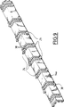
図1および図2は、加圧水型原子炉の新たな燃料集合体のための輸送コンテナを示しており、全体を通して参照番号1で表される。
【0017】
水平位置にある二つの燃料集合体を輸送するように設計された輸送容器1は、下部シェル2aおよび上部シェル2bで形成された外部エンベロープ2を有している。これらのシェルは両者とも半円筒形であり、円筒形エンベロープの長手軸を通るエンベロープ2の結合面に沿って、一方が他方の頂部に結合される。
【0018】
シェル2aおよび2bの夫々は鋼シートで作製され、それぞれ半型シェルの長さに亘って配置された半円形の補強リブ3a,3bを有している。
【0019】
セクション4および4´もまた,下部半型シェル2aの下方部分に固定され、該セクションはコンテナの支持足を形成している。更に、ネジ型ジャッキを有し且つコンテナの長手方向端部に固定された調節可能な支持部材5および5´は、支持表面に載置されたコンテナが、コンテナの長手軸回りおよび横断軸回りでの傾斜を調節されることを可能にする。コンテナの調節可能な足5および5´を使用することにより、該コンテナをその輸送支持体上で、好ましくは水平位置に、即ち、コンテナの長手軸が好ましくは水平である位置に配置することを可能にする。
【0020】
二つの半型シェル2aおよび2bは、コンテナの下部半型シェル2aにおける上部平面支持部および上部半型シェル2bの下部平面支持部を形成する矩形の周辺フランジを介して、一方が他方の頂面に一体化される。
【0021】
図1および図2に示すコンテナの閉鎖位置において、二つの半型シェル2aおよび2bのフランジは、ボルトおよびナットによって一方を他方の頂面に一体化および固定されて、アセンブリーのフランジ6を形成する。
【0022】
図3Aおよび図3Bは開放状態、即ち、コンテナエンベロープの上部半型シェルが下部半型シェルから分離され、除去された状態にあるコンテナの一部を示している。
【0023】
図3Aおよび図3Bは、全体を参照番号7で示したコンテナの内部構造を示しており、これは特に、コンテナ外部エンベロープ2の下部半型シェル2aにおいて、緩衝材パッドによって形成された支持体9上に載置された受台8を有する。コンテナ内部構造の第二の部分は、水平位置に並べて配置された二つの燃料集合体を収容し支持するためのユニット10によって形成される。受台8の上に載置されるユニット10は、以下で説明するように、二つの燃料集合体のための二つの完全に閉じたハウジングを形成する。
【0024】
受台8は、支持体パッド9上に固定された角ブラケットで形成された二つの側部レール8a,8bを有している。これらは平行な位置に保持されており、交差部材によって、コンテナを収容するためにユニット10の幅に対応して分離されている。その一端において、受台は旋回補強および装着ユニットを有し、これは相互に平行な2枚のプレート11aおよび11bと、受台の側部レールに固定され且つプレート11aおよび11bに固定された中空セクションで形成された2つの交差部材とを具備する。
【0025】
受台を横断方向の水平軸回りで旋回できるようにコンテナの下部シェルに装着することは、プレート11aおよび11bを具備する旋回する補強および装着ユニットによって保証される。
【0026】
更に、以下で説明するように、燃料集合体のための保持プレートもまた、プレート11aおよび11bの間に装着される。
【0027】
図3Bに見られるように、内部構造7の長手方向端部と外部エンベロープ2の内部円形端壁との間には、燃料集合体に対する衝撃(例えばコンテナの落下による)の効果を制限するような方法で、緩衝材43が挿入される。断面がコンテナエンベロープの内部断面と同一であるディスク形状の緩衝材43は、ステンレス鋼シート製エンベロープに囲まれたバルサディスク(balsa disc)製である。勿論、コンテナの長手方向の第二の端部においても、内部構造の第二の長手方向端部と外部エンベロープの第二の端部との間に、同一の緩衝材が配置される。
【0028】
図4に見られるように、燃料集合体支持体収容ユニット10は、T字形の断面を有する枠体12と、以下で説明するように枠体12の側部で旋回するように装着された二つのドア14aおよび14bを有している。
【0029】
図4に示すように、閉じた位置のドアにおいて、ドア14aは、枠体12の右側部分と共に一つの燃料集合体のためのハウジング13aを形成し、またドア14bは、枠体12の左側部分と共に第二のハウジング13bを形成する。これらのハウジングは矩形断面を有し、該断面は、コンテナ1によって輸送を保証される加圧水型原子炉燃料集合体のスペーサー格子の断面寸法を有する。
【0030】
当該コンテナを装荷するために、受台8は、該受台の一端に位置する横断軸まわりに、実質的に垂直な位置へと傾斜される。
【0031】
この受台の傾斜位置においては、受台に固定される燃料集合体収容支持ユニット10もまた垂直位置にある。ドア14aおよび14bは、ハウジング13aおよび13bへのアクセスを与えるような方法で、外側に向かって傾斜する。
【0032】
燃料集合体は、燃料集合体リフト器具、例えば高架クレーンのホイストを使用して、ハウジング13a,13bの夫々の中に配置すればよい。この燃料集合体は、それらの底部ノズルを介して、受台8の二つのプレート11aおよび11bの間に固定された燃料集合体支持プレート上に載置される。
【0033】
燃料集合体収容支持ユニット10のドアは閉じられ、該ユニットは水平位置へと傾斜され、受台8上に載置されるに至る。
【0034】
エンベロープ2の上部半型シェルを下部半型シェル上に戻し、この二つの半型シェルをボルトおよびナットで固定した後に、例えば、図1に示すように、外部エンベロープの上部半型シェルに固定されたリフトラグ15および15´を使用してコンテナを持ち上げることにより、該コンテナを取り扱い且つ輸送することができる。
【0035】
図5は受台8、並びに燃料集合体収容支持ユニット10を形成する種々の部材の分解斜視図を示している。
【0036】
T字形の横断面を有する枠体12は平行六面体の基部12aと、該基部12aに対して直交し、二つの燃料集合体16aおよび16bのハウジング13aおよび13bを分離する壁12bとを有しており、そのスペーサー格子17aおよび17b、底部ノズル18aおよび18b、並びに頂部ノズル18´aおよび18´bが示されている。
【0037】
受台8のプレート11aおよび11bの間で、スタブシャフトを介して旋回するように固定されることを目的とした支持プレート20と、枠体12の第二の端部において横断旋回軸の回りで旋回するように装着された第二の端部プレート21とによって、燃料集合体16aおよび16bのハウジング13aおよび13bが、フレーム12の端部の一方に形成されている。これら燃料集合体は、それらの頂部ノズル18´aおよび18´bを介して、プレート20の上に載置される。横断保持プレート21は、燃料集合体の底部ノズル18´aおよび18´b上に、調節可能な支持用端止め(supporting end-stops)を有している。プレート21はまた、燃料集合体を長手方向に保持するための調節可能な手段を有することができるであろう。
【0038】
端部プレート20および21がそれらの閉鎖位置へと引き下されると、燃料集合体は、支持装置22およびプレート20の間にクランプされることによって、長手方向に保持される。
【0039】
燃料集合体16aおよび16bを保持し且つ支持するユニット10の旋回する横方向ドア14aおよび14bは、逆L字形の断面を有し、またそれらの下縁に沿ってL字の枝の一方の端部に、ドア14aおよび14bの長さに亘って離間したヒンジ形状の関節部材23を有する。
【0040】
図5に示すドアは、ドア14aまたは14bにおける第一の下縁の長さに亘って離間した6個つのヒンジ23を有する。
【0041】
その対向する第二の縁部に沿った、L字の第二の枝の端部において、ドア14aおよび14bの夫々は、開口が貫通した部分を有し且つドアの縁部に対して外側に向かってわずかに突出した固定ラグ24を有している。
【0042】
ヒンジ形状の関節部材23は、ドアの縁部に対して平行な方向に全て整列した開口を有しており、夫々は燃料集合体支持体の枠体12における基部12aの横方向縁部から突出するように固定された関節軸25上に係合する。同様に、ドアの第二の縁部に沿って配置されたラグ24から突出した部分の開口は、ドアの縁部に平行な方向に整列される。
【0043】
枠体12の中央壁12bは、その上縁に、枠体12の中央壁12bの上縁に対して平行な方向に全て整列された開口をもった案内部材26および26´を有している。
【0044】
ヒンジ23を介して関節軸25上に関節式に装着されたドアが閉鎖位置に引かれると、ドア14aおよび14bの第二の縁部(これに沿ってラグ24が配置される)は、枠体12の中央壁12bの上縁に引かれ、夫々のラグ24は、枠体12における中央壁12bの上部縁に固定された二つの連続的な案内ポスト26および26´の間に挿入された位置に来る。ドア14aおよび14bは、それらが閉鎖位置にあるときは、案内部材26および26´並びにラグ24の整列した開口の中にロッドを導入することによってロックすることができる。
【0045】
更に、ドア14aおよび14bは、それらの長手方向端部に、それぞれ長手方向外側に向かって突出した掛け釘27a,27´aおよび27b,27´bを有する。
【0046】
枠体12の縁部プレート20および21は、それらの上部縁および横縁に沿ってスロット28および28´を有し、その夫々は、端部壁20および21が引き下された後のドアの閉鎖位置で、掛け釘27aもしくは27bの一方または掛け釘27´aもしくは27´bの一方をそれぞれ受け入れることを目的としたものである。
【0047】
更に、壁20および21は、それらを貫通し、且つハウジング13aおよび13bの内側のそれらの輸送位置において燃料集合体の夫々のノズルに対面する開口を有する。
【0048】
二つの側面が枠体12の二つの相互に直交する表面によって、それに対向する側面がドア14aおよび14bの二つの内部直交表面によって、またその両端部がプレート20および21によって構成される燃料集合体ハウジング13aまたは13bの各々が、完全に閉じられ、燃料集合体の効果的な閉じ込めを保証する。コンテナが衝撃を受けて燃料集合体の部分的な破壊を生じたとしても、燃料集合体の断片、例えば燃料ペレットまたは燃料棒の断片は、燃料集合体ハウジングから出てコンテナ内に広がることができない。
【0049】
旋回するように装着されるドア14aおよび14bおよび端壁20および21は、燃料集合体ハウジングへのアクセスを与えるように開放されることができる、燃料集合体のための二つのハウジングを有するボックスを形成する。
【0050】
更に、以下で説明するように、枠体の基部12aおよび中央壁12b、並びにドア14aおよび14bの壁は二重壁の形態で構成され、その厚みの内部には中性子吸収性樹脂、即ち中性子を強力に吸収する元素を添加した合成樹脂が配置される。
【0051】
図6は、燃料集合体収容支持ユニットの枠体12を形成する部材の分解斜視図を示している。
【0052】
枠体12は、溶接されたリブ29によって、また横行セクション31によって補強された基部プレート30を有しており、ドア14a,14bのための関節軸25、および枠体12をボルトおよびナットを介して受台8の側面に固定するためのラグ32が横行セクション31の端部に固定される(図7および図8)。
【0053】
夫々のセクション30の両側、プレート29の頂部、その中央部分には、支柱33がプレート29に対して直角に固定されている。支柱33の上部には、燃料集合体収容支持ユニットのドアをロックする手段を案内するための部材26´が固定されている。
【0054】
枠体12を形成する第二の部材は、二つの敷居によって底部方向に伸び、L字形に折りたたまれた金属シート34の二つの部材からなり、それらの部材の上部が折り畳みおよび/または取りつけられた部材によって結合され、該部材は、枠体12の中央壁12bの上縁を案内するための案内部分26を形成する、折り畳まれた金属シート34内に輪郭取りされた部材である。
【0055】
輪郭取りされたシート金属部材34の折り畳まれた側縁には、ドアの間接軸のための通路、および補強セクション31の端部に固定される、枠体12を受台上に固定するためのパッドが設けられている。
【0056】
二つのT字形スペーサー部材35aおよび35bが、プレート29の端部に固定される。
【0057】
枠体12は、折り畳まれたシート金属部材34と、補強部材および支柱33を有する基部プレート29とを組み立てることにより製造される。
【0058】
基部プレート30の端部スペーサー35aおよび35bが、折り畳まれたシート金属部材34の内部プロファイルの中に挿入される。同様に、六つの支柱33は、折り畳まれたシート金属部材34の内部プロファイルの垂直部分、即ち、二つのL字形横方向シート金属部材の二つの垂直枝の間に挿入される。
【0059】
支柱の端部に固定された案内部材26´は、二つのL字形の折り畳まれたシート金属部材を、T字形横断面を有する輪郭取りされた部材34の形態に結合している連続した二つの案内部材26の間に挿入される。
【0060】
枠体12の組み立てられた位置において、L字形に折り畳まれたシート金属部材の水平部分は、シート金属部材34の水平部分と基部プレート29との間に空隙が維持されるように、スペーサー35およびセクション31上に載置される。
【0061】
図8に見られるように、この自由スペース36には中性子吸収性樹脂が充填される。該樹脂は、その密度が1.5〜2である高密度樹脂である。
【0062】
同様に、シート金属部材24の垂直部分間の空隙37には、高密度中性子吸収性樹脂が充填される。この樹脂およびスペーサー部材は、枠体12の機械的一体性を保証する。
【0063】
プレート30、その補強部材および支柱33を折り畳まれたシート金属部材34と共に組み立てることによって、二重壁の剛性枠体12が得られる。二重壁の空隙36および37に中性子吸収性樹脂を充填することによって、その基部プレート12aおよび分離中央壁12bが、枠体12のハウジング13aおよび13b内に配置された燃料集合体から発生した中性子フラックスを吸収できる枠体が得られる。
【0064】
図9は、燃料集合体収容支持ユニットの右側ドア14aを示している。
【0065】
ドア14a(および同様の第二のドア14b)はL字形に折り畳まれたシート金属部材によって形成され、該シート金属部材はL字の枝の端部において、一方の枝の延長部、関節部分23およびロックラグ24によって相互に結合される。
【0066】
更に、L字形ドアを形成する二つの金属シートの間には、ドア14aの長さに亘って、スペーサー38が相互に一定の距離で配置される。
【0067】
図10に見られるように、夫々のスペーサー38は、ドアの長手方向に相互に離間され且つそれらの端部においてそれぞれ関節部分25およびロックラグ24に固定された二つのL字形プレートを有している。
【0068】
ドアによって形成されたハウジング内に配置される燃料集合体クランプ装置は、二つのL字形プレート間の各スペーサ38においてL字の各枝に固定され、燃料集合体が横断方向に保持されることを保証する。
【0069】
図10に見られるように、夫々のクランプ装置39は平坦なパッド40を有し、該パッドは、それをドアのL字の枝に対して直交する方向に動かすために、ネジ41によって、内部にロック装置39が装着されたドアの外側から操作することができる。
【0070】
夫々のスペーサー38において、ドア14aは、ドア14aで形成されるハウジング内に配置された燃料集合体におけるスペーサー格子の二つの外面に接触することを目的とした、二つのクランプ装置39を有する。この方法において、燃料集合体は、そのハウジング内において、二つの相互に直交する側面にクランプされる。
【0071】
図11は、L字形プレート41により閉鎖されるドア14aの長手方向端部を示しており、このプレートには、ドア14aを端壁21に固定するための外側に突出した掛け釘27が固定される。図11の切り欠き部分に見られるように、ブロック棒42が、ドア14aの上部水平壁における整列した開口内および掛け釘7の間で摺動するように装着される。更に、棒42はドア14aの外側から操作可能である。
【0072】
ドア14aが閉鎖位置にあり、また端部プレート20(または21)が燃料集合体収容支持ユニットのハウジングにおける長手方向端部の閉鎖位置に引き下ろされると、棒42は、スロット28間のプレート20(または21)の外側部分横断方向に貫通する整列した開口の中に、またプレート20(または21)の開口に整列して配置された掛け釘27a間の開口の中に導入されることができる。
【0073】
この方法において、端部閉鎖プレート20および21は、ドア14aの端部にロックされる。
【0074】
当然ながら、掛け釘27aおよび27´aを有するドア14aの夫々の端部も、同様の方法でロックされることができる。
【0075】
同じロック棒42は、プレート20(または21)および掛け釘27b(または27´b)の開口の中に導入されることによって、第二のドア14bをロックすることができる。
【0076】
ドア14aおよび14bのL字形壁における二つの部材間の空隙には、燃料集合体から発生して燃料集合体収容支持ユニットの外側に向かう如何なる中性子フラックスをも吸収するために、中性子吸収性樹脂が充填される。この高密度(1.5〜2の密度)を有する樹脂およびスペーサーは、ドアの機械的一体性を保証する。
【0077】
本発明によるコンテナの内部構造は、燃料集合体のための完全に閉鎖される二つのハウジングを形成し、その内部には軸方向または長手方向に、燃料集合体が横向きに保持される。ハウジングが完全に閉鎖されるので、何等かの衝撃によって燃料集合体の部分的な破壊が起きたとしても、燃料集合体の一部は内部構造から逃げることができず、これは燃料集合体の閉じ込めを保証する。従って、燃料集合体の断片はコンテナの外部エンベロープの内部に広がることができない。
【0078】
更に、燃料集合体は、中性子吸収壁によってコンテナの内部構造内で相互に分離される。
【0079】
また、内部構造によって形成された燃料集合体ハウジングは、外側で、即ち、コンテナの外部エンベロープの内部表面に向けてハウジングを閉鎖する中性子吸収壁を有する。
【0080】
従って、燃料集合体の輸送の際に、一以上の燃料集合体輸送の際に臨界に達する危険を低減すると同時に、コンテナ内部での燃料集合体の改善された機械的保護が得られる。
【0081】
本発明は、上記で説明した実施例に限定されない。
【0082】
こうして、コンテナの内部構造は、既述のものとは異なった形状を有していてもよく、またT字形枠体および傾斜ドア以外の部材を有していてもよい。コンテナの内部構造中のハウジングの形状は、輸送される燃料集合体の形状に依存する。全ての場合において、この内部構造は、少なくとも一つの完全に閉鎖された燃料集合体収容支持ハウジングを形成するように、相互に組立てられた壁を有する。
【0083】
本発明は、直角柱形状を有する如何なる核燃料集合体の輸送にも適用可能である。本発明によるコンテナは、新たな燃料集合体の輸送のためだけでなく、低い放射能を有する使用済み燃料集合体の輸送にも使用することができる。
【図面の簡単な説明】
【図1】 図1は、輸送のために閉じた構造のコンテナを示す側面図である。
【図2】 図2は、図1の矢印2の方向から見た端面図である。
【図3A】 図3Aは、コンテナの内部構造を示すために、外部エンベロープの上部シェルを除去したコンテナの一部を示す正面図である。
【図3B】 図3Bは、図3Aの矢印3Bから見た、開いたコンテナの頂面図である。
【図4】 図4は、図3Aまたは図3Bの4−4線に沿った端面図である。
【図5】 図5は、燃料集合体輸送コンテナの内部構造を形成する部材の分解斜視図である。
【図6】 図6は、コンテナ内部構造の燃料集合体支持枠体を形成する部材を示す分解斜視図である。
【図7】 図7は、コンテナ内部構造の燃料集合体支持枠体を示す頂面図である。
【図8】 図8は、図7の線8−8に沿った横断面図である。。
【図9】 図9は、燃料集合体輸送コンテナの内部構造の横方向ドアを示す斜視図である。
【図10】 図10は、燃料集合体を横方向に保持する装置のレベルでの、横方向ドアの横断面図である。
【図11】 図11は、輸送コンテナ内部構造の横方向ドアを一部切り欠いて示す端面図である。[0001]
The present invention relates to a nuclear fuel assembly transport container, and more particularly to a transport container for a new fuel assembly intended to replenish nuclear fuel to a pressurized water reactor.
[0002]
A nuclear reactor, such as a pressurized water reactor, generally has a core made of a nuclear fuel assembly in the shape of a narrow right prism having a square cross section. The fuel assembly has a generally rectangular cross section with a lateral length of approximately 20 cm, the longitudinal length of the fuel assembly being about 4 meters. This fuel assembly has a frame, and nuclear fuel rods are arranged inside the frame substantially along the entire length of the fuel assembly. The frame itself is made up of a spacer grid that holds the rods arranged across the length of the fuel assembly in the lateral direction, and the spacer grid is parallel to the rods embedded in the spacer grid. And a fuel assembly end nozzle.
[0003]
Before starting the reactor, it is necessary to supply a new fuel assembly to the core. Some core assemblies must be replaced after a certain period of time. New fuel assemblies need to be replaced with spent fuel assemblies that are either loaded into the core or removed from the reactor core. Therefore, it is necessary to obtain a new fuel assembly available that must be transported from the fuel production plant to a nuclear station where fuel is supplied or resupplied to the reactor core.
[0004]
Transportation of new fuel assemblies carried out by rail or land may use a shipping container that ensures effective protection of the fuel assemblies whose rods are not laterally protected between two consecutive spacer grids. I need. The shipping container must also be designed to avoid or limit the destruction of the fuel assembly, for example, when shipping, if the container falls during a transshipment operation of the container.
[0005]
Fuel assembly shipping containers are known, which have an outer envelope, which is made of sheet metal made in the shape of two half-shells of approximately semi-cylindrical shape, one of which is diametrically oriented in the container. It is manufactured by fixing and integrating on the other top part along the rectangular frame arrange | positioned at the axial surface of this. This container is generally designed for transporting two fuel assemblies and has a frame on which the two fuel assemblies can be fixed. The frame is placed on a cradle fixed via a buffer member in the lower half of the outer envelope of the container.
[0006]
The frame for supporting and holding the fuel assembly has a position for loading the fuel assembly (the support is substantially vertical in this position) and a transport position (which supports the fuel assembly in this position). Is mounted so as to pivot on the cradle by one of its ends so that it can move between the frame and the cradle for mounting on the cradle in a substantially horizontal position.
[0007]
The frame for supporting the fuel assembly has a T-shaped cross section, which has a base for supporting the fuel assembly and a longitudinal central wall perpendicular to the base. The base supports the fuel assembly, and the central wall forms two housings on either side of which the fuel assembly can be placed. The fuel assembly is held in the frame via a flange articulated to a lateral end of the base and an upper end of the central wall of the frame, the flange being a housing of the fuel assembly Can be moved between an open position where the flange is accessible and a closed position where the flange holds the fuel assembly. The flanges are assembled to each other in their closed positions by bolt and nut assemblies and arranged over the length of the frame, within the continuous housing grid of each fuel assembly, within the frame housing. Is placed in contact with the fuel assembly arranged in the above.
[0008]
The transport container is designed so that the fuel assemblies arranged side by side at the transport location cannot form a critical mass that leads to the start of the neutron chain reaction at any time. In general, to avoid any danger of criticality, it is necessary to place a neutron absorbing member between the fuel assemblies at the transport location within the container.
[0009]
Furthermore, when the fuel assembly deteriorates or breaks down, for example, when the container falls, and the protective cladding layer of the fuel rods bursts, there is a risk that the fissile material contained in the fuel assembly will spread. It is necessary to suppress as much as possible.
[0010]
In the case of known transport containers, neutron-absorbing insulation means for the fuel assemblies are inadequate, and the containers enable effective containment of fissile material when the fuel assemblies are degraded inside the container It is known that it does not have a structure to make. This is because the fuel assemblies are not protected and contained within the outer envelope of the container, and the frame is spaced apart in the longitudinal direction of the fuel assemblies, similar to the spacer grid. It only has a means for holding the fuel assembly in the form of a flange.
[0011]
Furthermore, the simulation of the dynamic behavior of the container and fuel assembly when the fuel assembly falls in the axial direction or when it falls horizontally causes the container and fuel assembly to be contained within the frame and container envelope. It can be shown that very effective energy absorption needs to be available to ensure the mechanical integrity of the engineered fuel assembly.
[0012]
Thus, it seems desirable to have an available shipping container that guarantees improved protection for the fuel assemblies.
[0013]
Accordingly, it is an object of the present invention to provide a transport container for a right prism shaped nuclear fuel assembly having an internal structure that forms an outer envelope and at least one housing for receiving and holding the fuel assembly. It is another object of the present invention to provide a transportation container for a nuclear fuel assembly having a right prism shape having a side surface disposed over a right prism surface of the housing and an end surface at each longitudinal end of the housing. This shipping container provides effective protection for the fuel assemblies being transported and prevents the fissile material from spreading within the outer envelope of the container when the fuel assemblies are degraded or destroyed. To prevent, it includes a fissile material contained in a fuel assembly.
[0014]
For this purpose, the internal structure of the container is such that at least one housing for containing and holding the fuel assembly is completely closed along its side and at its longitudinal end, and the internal structure is external Independent of the envelope, assembled together to ensure the retention, protection and containment of the fuel assembly
The internal structure forms a case for containing at least one fuel assembly, which can be opened to provide access to the fuel assembly housing.
[0015]
To facilitate an understanding of the present invention, a new fuel assembly transport container according to the present invention for a pressurized water reactor will be described with reference to the accompanying drawings.
[0016]
1 and 2 show a transport container for a new fuel assembly of a pressurized water reactor, denoted by
[0017]
A
[0018]
Each of the
[0019]
Sections 4 and 4 'are also fixed to the lower part of the
[0020]
The two
[0021]
In the closed position of the container shown in FIGS. 1 and 2, the flanges of the two half-
[0022]
3A and 3B show a portion of the container in an open state, i.e., with the upper half shell of the container envelope separated and removed from the lower half shell.
[0023]
FIGS. 3A and 3B show the internal structure of the container, indicated generally by the
[0024]
The
[0025]
The mounting of the cradle on the lower shell of the container so that it can be swiveled about a transverse horizontal axis is ensured by the swiveling reinforcement and mounting unit comprising the
[0026]
Further, as will be described below, a holding plate for the fuel assembly is also mounted between the
[0027]
As seen in FIG. 3B, between the longitudinal end of the
[0028]
As shown in FIG. 4, the fuel assembly
[0029]
As shown in FIG. 4, in the door in the closed position, the door 14 a forms a
[0030]
To load the container, the
[0031]
In the inclined position of the cradle, the fuel assembly
[0032]
The fuel assembly may be placed in each of the
[0033]
The door of the fuel assembly
[0034]
After the upper half shell of the
[0035]
FIG. 5 is an exploded perspective view of various members forming the
[0036]
The
[0037]
Between the
[0038]
As the
[0039]
The swiveling
[0040]
The door shown in FIG. 5 has six
[0041]
At the end of the L-shaped second branch along its opposing second edge, each of the
[0042]
The hinge-shaped
[0043]
The
[0044]
When the door, which is articulated on the
[0045]
Furthermore, the
[0046]
The
[0047]
Furthermore, the
[0048]
A fuel assembly in which two side surfaces are constituted by two mutually orthogonal surfaces of the
[0049]
The
[0050]
Further, as will be described below, the base 12a and the
[0051]
FIG. 6 shows an exploded perspective view of members forming the
[0052]
The
[0053]
Support columns 33 are fixed at right angles to the
[0054]
The second member forming the
[0055]
The folded side edges of the contoured
[0056]
Two T-shaped spacer members 35 a and 35 b are fixed to the end of the
[0057]
The
[0058]
End spacers 35 a and 35 b of the
[0059]
Guide members 26 'secured to the ends of the struts are two successive two joining the two L-shaped folded sheet metal members in the form of a contoured
[0060]
In the assembled position of the
[0061]
As can be seen in FIG. 8, this
[0062]
Similarly, the
[0063]
By assembling the
[0064]
FIG. 9 shows the right door 14a of the fuel assembly housing support unit.
[0065]
The door 14a (and a similar
[0066]
Further, a
[0067]
As can be seen in FIG. 10, each
[0068]
A fuel assembly clamping device disposed in a housing formed by a door is secured to each L-shaped branch at each spacer 38 between the two L-shaped plates to ensure that the fuel assembly is held in the transverse direction. Guarantee.
[0069]
As can be seen in FIG. 10, each clamping
[0070]
In each
[0071]
FIG. 11 shows a longitudinal end portion of the door 14a closed by the L-shaped
[0072]
When the door 14a is in the closed position, and the end plate 20 (or 21) is pulled down to the closed position at the longitudinal end of the housing of the fuel assembly housing support unit, the rod 42 is moved to the
[0073]
In this way, the
[0074]
Of course, the respective ends of the door 14a with the
[0075]
The same lock bar 42 can be locked into the
[0076]
In the gap between the two members of the L-shaped walls of the
[0077]
The internal structure of the container according to the invention forms two completely closed housings for the fuel assembly, in which the fuel assembly is held laterally, axially or longitudinally. Because the housing is completely closed, even if some impact causes partial destruction of the fuel assembly, part of the fuel assembly cannot escape from the internal structure, which Ensuring confinement. Therefore, fuel assembly fragments cannot spread within the outer envelope of the container.
[0078]
Furthermore, the fuel assemblies are separated from each other within the internal structure of the container by neutron absorbing walls.
[0079]
The fuel assembly housing formed by the internal structure also has a neutron absorbing wall that closes the housing on the outside, i.e., toward the inner surface of the outer envelope of the container.
[0080]
Thus, when transporting fuel assemblies, the risk of reaching criticality during transport of one or more fuel assemblies is reduced while at the same time improved mechanical protection of the fuel assemblies within the container is obtained.
[0081]
The invention is not limited to the embodiments described above.
[0082]
Thus, the internal structure of the container may have a shape different from that described above, and may have members other than the T-shaped frame and the inclined door. The shape of the housing in the internal structure of the container depends on the shape of the fuel assembly being transported. In all cases, the internal structure has walls assembled together to form at least one fully closed fuel assembly containing support housing.
[0083]
The present invention is applicable to the transportation of any nuclear fuel assembly having a right prism shape. The container according to the invention can be used not only for transporting new fuel assemblies, but also for transporting spent fuel assemblies with low radioactivity.
[Brief description of the drawings]
FIG. 1 is a side view showing a container in a closed structure for transportation.
FIG. 2 is an end view seen from the direction of
FIG. 3A is a front view of a portion of the container with the upper shell of the outer envelope removed to show the internal structure of the container.
FIG. 3B is a top view of the open container as seen from the
4 is an end view taken along line 4-4 of FIG. 3A or FIG. 3B.
FIG. 5 is an exploded perspective view of members forming the internal structure of the fuel assembly transport container.
FIG. 6 is an exploded perspective view showing members forming a fuel assembly support frame of the container internal structure.
FIG. 7 is a top view showing a fuel assembly support frame having a container internal structure.
FIG. 8 is a cross-sectional view taken along line 8-8 of FIG. .
FIG. 9 is a perspective view showing a lateral door of the internal structure of the fuel assembly transport container.
FIG. 10 is a cross-sectional view of the lateral door at the level of the device for holding the fuel assembly in the lateral direction.
FIG. 11 is an end view showing a partially cutaway lateral door of the transport container internal structure.
Claims (8)
前記輸送コンテナの内部構造(7)は、少なくとも一つの燃料集合体を支持するための枠体(12)をもった少なくとも一つの燃料集合体のための収容支持ユニット(10)を有し、前記枠体(12)は、燃料集合体(16a,16b)の二つの側面を支持する少なくとも二つの壁(12a,12b)、および燃料集合体(16a,16b)の長手方向端部を保持するための二つの枠体(12)に対して旋回可能な端部プレート(20,21)を具備し、前記収納支持ユニット(10)は、さらに、前記ハウジング(13a,13b)に対するアクセスを与える開放位置と、端部プレート(20,21)および枠体(12)と共に前記ハウジング(13a,13b)の完全な閉鎖を保証するとともに前記外部エンベロープ(2)とは独立して燃料集合体(16a,16b)の保護および閉じ込めを保証する閉鎖位置との間で旋回するように、枠体(12)に装着された少なくとも一つのドア(14a,14b)を具備する、ことを特徴とする輸送コンテナ。An external envelope (2) and an internal structure (7) forming at least one housing (13a, 13b) for receiving and holding the fuel assembly (16a, 16b), and the housing (13a, 13b) In a transport container for a fuel assembly in the form of a right prism having a side face arranged along the surface of the right pillar and an end face at each longitudinal end of the housing (13a, 13b),
The internal structure of the transport container (7) has at least one housing support unit for the fuel assembly having at least a frame for supporting one of the fuel assemblies (12) (10), wherein The frame (12) holds at least two walls (12a, 12b) supporting two side surfaces of the fuel assembly (16a, 16b) and a longitudinal end of the fuel assembly (16a, 16b). End plates (20, 21) that can pivot with respect to the two frames (12), and the storage support unit (10) further provides an open position for providing access to the housing (13a, 13b) . When, the above the external envelope (2) as well as ensure a complete closure of the housing (13a, 13b) with end plates (20, 21) and the frame (12) independently Comprising at least one door (14a, 14b) mounted on the frame (12) so as to pivot between a closed position ensuring the protection and containment of the material assembly (16a, 16b). Featured shipping container.
Applications Claiming Priority (3)
| Application Number | Priority Date | Filing Date | Title |
|---|---|---|---|
| FR9801553A FR2774800B1 (en) | 1998-02-10 | 1998-02-10 | TRANSPORT CONTAINER FOR NUCLEAR FUEL ASSEMBLIES |
| FR98/01553 | 1998-02-10 | ||
| PCT/FR1999/000218 WO1999041754A1 (en) | 1998-02-10 | 1999-02-02 | Transport container for nuclear fuel assemblies |
Publications (3)
| Publication Number | Publication Date |
|---|---|
| JP2002503821A JP2002503821A (en) | 2002-02-05 |
| JP2002503821A5 JP2002503821A5 (en) | 2006-03-02 |
| JP4322423B2 true JP4322423B2 (en) | 2009-09-02 |
Family
ID=9522794
Family Applications (1)
| Application Number | Title | Priority Date | Filing Date |
|---|---|---|---|
| JP2000531852A Expired - Fee Related JP4322423B2 (en) | 1998-02-10 | 1999-02-02 | Transport container for nuclear fuel assemblies |
Country Status (9)
| Country | Link |
|---|---|
| US (1) | US6580085B1 (en) |
| EP (1) | EP1055241B1 (en) |
| JP (1) | JP4322423B2 (en) |
| KR (1) | KR100654080B1 (en) |
| CN (1) | CN1128451C (en) |
| DE (1) | DE69903922T2 (en) |
| ES (1) | ES2187137T3 (en) |
| FR (1) | FR2774800B1 (en) |
| WO (1) | WO1999041754A1 (en) |
Cited By (2)
| Publication number | Priority date | Publication date | Assignee | Title |
|---|---|---|---|---|
| US9117555B2 (en) | 2009-07-31 | 2015-08-25 | Mitsubishi Heavy Industries, Ltd. | Transportation container of fuel assembly |
| WO2023214610A1 (en) * | 2022-05-03 | 2023-11-09 | 한전원자력연료 주식회사 | Transport container for fresh nuclear fuel assembly for light-water reactor |
Families Citing this family (27)
| Publication number | Priority date | Publication date | Assignee | Title |
|---|---|---|---|---|
| FR2805655B1 (en) * | 2000-02-24 | 2002-07-19 | Transnucleaire | CONTAINER WITH DOUBLE ENCLOSURE FOR THE TRANSPORT OR STORAGE OF RADIOACTIVE MATERIAL |
| US6748042B1 (en) * | 2003-04-28 | 2004-06-08 | Westinghouse Electric Company Llc | Unirradiated nuclear fuel component transport system |
| US20050286674A1 (en) * | 2004-06-29 | 2005-12-29 | The Regents Of The University Of California | Composite-wall radiation-shielded cask and method of assembly |
| FR2905031B1 (en) * | 2006-08-21 | 2008-11-07 | Areva Np Sas | TRANSPORT CONTAINER FOR NUCLEAR FUEL ASSEMBLIES AND USE OF SUCH CONTAINER. |
| JP2008224460A (en) * | 2007-03-13 | 2008-09-25 | Ihi Corp | Canister storage container |
| KR101228891B1 (en) * | 2007-10-19 | 2013-02-04 | 아레바 페더럴 서비시즈 엘엘씨 | Package assemblies and internal support structures for transport and storage of radioactive materials |
| FR2925975B1 (en) * | 2007-12-26 | 2016-05-27 | Areva Np | TRANSPORT CONTAINER FOR NUCLEAR FUEL ASSEMBLY, AND METHOD FOR TRANSPORTING A NUCLEAR FUEL ASSEMBLY |
| KR101180858B1 (en) * | 2010-07-12 | 2012-09-07 | 한전원자력연료 주식회사 | Lid frame with gap compensator to fill in a space between lid frame and fresh nuclear fuel assembly and the shipping container |
| KR101170080B1 (en) * | 2010-07-12 | 2012-07-31 | 한전원자력연료 주식회사 | Lid frame of the shipping container transporting fresh nuclear fuel assemblies and the shipping container |
| CN101964216B (en) * | 2010-09-27 | 2012-12-26 | 郭泽学 | Novel radioactive source transporting and storing case |
| RU2543058C2 (en) * | 2013-07-18 | 2015-02-27 | Открытое акционерное общество "Новосибирский завод химконцентратов" (ОАО "НЗХК") | Container for transportation of fuel assemblies of nuclear reactor |
| CN103474120B (en) * | 2013-09-12 | 2016-06-08 | 中国核电工程有限公司 | A kind of nuclear fuel assembly transport container component protection device |
| CN103474119B (en) * | 2013-09-12 | 2016-04-27 | 中国核电工程有限公司 | Nuclear fuel assembly cask |
| JP2015166719A (en) * | 2014-03-04 | 2015-09-24 | 株式会社リカナル | Radiation shielding container for transportation |
| CN104575648B (en) * | 2014-12-24 | 2017-05-03 | 中国原子能科学研究院 | Conveying container for fast reactor MOX fuel component |
| CN105788665A (en) * | 2014-12-26 | 2016-07-20 | 中核建中核燃料元件有限公司 | Device for assembling and supporting fuel assemblies |
| KR101630401B1 (en) * | 2015-04-15 | 2016-06-15 | 한전원자력연료 주식회사 | Packing box for transporting PHWR fuel assembly |
| KR101693786B1 (en) | 2015-10-20 | 2017-01-06 | 한국전력기술 주식회사 | Spent Fuel Transfer Device for transferring spent fuel between the spent fuel storage pools |
| WO2020107180A1 (en) * | 2018-11-26 | 2020-06-04 | 中广核研究院有限公司 | Fuel assembly transport container |
| WO2020107182A1 (en) * | 2018-11-26 | 2020-06-04 | 中广核研究院有限公司 | Fuel assembly transportation container and top capping device thereof |
| WO2020107183A1 (en) * | 2018-11-26 | 2020-06-04 | 中广核研究院有限公司 | Fuel assembly transport container and bottom sealing device thereof |
| WO2020107179A1 (en) * | 2018-11-26 | 2020-06-04 | 中广核研究院有限公司 | Fuel assembly transport container and supporting assembly therefor |
| CN113302705B (en) * | 2020-04-08 | 2023-04-11 | 中广核研究院有限公司 | Quick locking device and method for support rod and fuel assembly transportation container |
| CN111446018A (en) * | 2020-04-09 | 2020-07-24 | 上海核工程研究设计院有限公司 | Nuclear fuel transport container shell with buffering heat absorption and moderating functions |
| CN111446017A (en) * | 2020-04-09 | 2020-07-24 | 上海核工程研究设计院有限公司 | Horizontal middle-open type double-component fuel transport container and dismounting method thereof |
| CN113130108B (en) * | 2021-03-05 | 2023-11-24 | 安徽中科超核科技有限公司 | Solidifying and transporting device and method based on solidifying fluid containing radioactive substance |
| CN114147433B (en) * | 2021-12-22 | 2023-08-08 | 上海阿波罗机械股份有限公司 | Manufacturing method of fuel transportation equipment |
Family Cites Families (12)
| Publication number | Priority date | Publication date | Assignee | Title |
|---|---|---|---|---|
| GB1145983A (en) * | 1965-05-07 | 1969-03-19 | Atomic Energy Authority Uk | Improvements in or relating to transport containers for radioactive materials |
| US3886368A (en) * | 1973-02-27 | 1975-05-27 | Nuclear Fuel Services | Spent fuel shipping cask |
| GB2055671B (en) * | 1979-07-18 | 1982-11-17 | British Nuclear Fuels Ltd | Transport and storage of irradiated nuclear fuel elements |
| DE2942092C2 (en) * | 1979-10-18 | 1985-01-17 | Steag Kernenergie Gmbh, 4300 Essen | Final storage containers for radioactive waste, in particular irradiated nuclear reactor fuel elements |
| GB2108036B (en) * | 1981-10-26 | 1985-05-22 | British Nuclear Fuels Ltd | Container for irradiated nuclear fuel |
| DE3320071A1 (en) * | 1983-06-03 | 1984-12-06 | Siemens AG, 1000 Berlin und 8000 München | ARRANGEMENT FOR RECEIVING BURNED NUCLEAR REACTOR FUEL BARS AND METHOD FOR HANDLING THE SAME |
| US4780268A (en) * | 1984-06-13 | 1988-10-25 | Westinghouse Electric Corp. | Neutron absorber articles |
| DE3610862A1 (en) * | 1986-04-01 | 1987-10-08 | Kernforschungsz Karlsruhe | LENGTH CYLINDRICAL CONTAINER FOR THE FINAL STORAGE OF ONE OR MORE CHILLERS FILLED WITH HIGH RADIOACTIVE WASTE |
| FR2674667B1 (en) * | 1991-03-25 | 1994-09-02 | Framatome Sa | DEVICE FOR FIXING AN OBJECT ON A TRANSPORT STRUCTURE AND IN PARTICULAR DEVICE FOR LOCKING A FUEL ASSEMBLY IN A TRANSPORT CONTAINER. |
| FR2674668B1 (en) * | 1991-03-25 | 1993-07-16 | Framatome Sa | DEVICE FOR FIXING AN OBJECT TO A TRANSPORT STRUCTURE AND IN PARTICULAR LOCKING DEVICE FOR A FUEL ASSEMBLY IN A CONTAINER. |
| US5481117A (en) * | 1994-09-01 | 1996-01-02 | Westinghouse Electric Corporation | Shipping container for a nuclear fuel assembly |
| JP2000131491A (en) * | 1998-10-23 | 2000-05-12 | Trans Nuclear Kk | Transportation cask |
-
1998
- 1998-02-10 FR FR9801553A patent/FR2774800B1/en not_active Expired - Fee Related
-
1999
- 1999-02-02 EP EP99901693A patent/EP1055241B1/en not_active Expired - Lifetime
- 1999-02-02 KR KR1020007008699A patent/KR100654080B1/en not_active IP Right Cessation
- 1999-02-02 CN CN99803806A patent/CN1128451C/en not_active Expired - Lifetime
- 1999-02-02 ES ES99901693T patent/ES2187137T3/en not_active Expired - Lifetime
- 1999-02-02 WO PCT/FR1999/000218 patent/WO1999041754A1/en active IP Right Grant
- 1999-02-02 JP JP2000531852A patent/JP4322423B2/en not_active Expired - Fee Related
- 1999-02-02 US US09/601,960 patent/US6580085B1/en not_active Expired - Lifetime
- 1999-02-02 DE DE69903922T patent/DE69903922T2/en not_active Expired - Lifetime
Cited By (2)
| Publication number | Priority date | Publication date | Assignee | Title |
|---|---|---|---|---|
| US9117555B2 (en) | 2009-07-31 | 2015-08-25 | Mitsubishi Heavy Industries, Ltd. | Transportation container of fuel assembly |
| WO2023214610A1 (en) * | 2022-05-03 | 2023-11-09 | 한전원자력연료 주식회사 | Transport container for fresh nuclear fuel assembly for light-water reactor |
Also Published As
| Publication number | Publication date |
|---|---|
| FR2774800A1 (en) | 1999-08-13 |
| CN1296625A (en) | 2001-05-23 |
| CN1128451C (en) | 2003-11-19 |
| ES2187137T3 (en) | 2003-05-16 |
| DE69903922D1 (en) | 2002-12-19 |
| JP2002503821A (en) | 2002-02-05 |
| FR2774800B1 (en) | 2000-05-05 |
| DE69903922T2 (en) | 2003-09-11 |
| WO1999041754A1 (en) | 1999-08-19 |
| EP1055241B1 (en) | 2002-11-13 |
| KR100654080B1 (en) | 2006-12-07 |
| EP1055241A1 (en) | 2000-11-29 |
| KR20010040805A (en) | 2001-05-15 |
| US6580085B1 (en) | 2003-06-17 |
Similar Documents
| Publication | Publication Date | Title |
|---|---|---|
| JP4322423B2 (en) | Transport container for nuclear fuel assemblies | |
| KR101602661B1 (en) | Transport container for nuclear fuel assembly and method of transporting a nuclear fuel assembly | |
| US9666318B2 (en) | Storage, transportation and disposal system for used nuclear fuel assemblies | |
| ES2344944T3 (en) | TRANSPORTATION SYSTEM OF NUCLEAR NON-IRRADIATED FUEL COMPONENTS. | |
| US6957942B2 (en) | Autonomous cask translocation crane | |
| JPH05249290A (en) | Flux trap neutron absorbing apparatus for nuclear fuel storage body | |
| JPS5828697A (en) | Fuel storage rack of reactor | |
| US6327321B1 (en) | Borated aluminum rodlets for use in spent nuclear fuel assemblies | |
| JP2011033471A (en) | Container for transporting fuel assembly | |
| CA1151780A (en) | Modular nuclear fuel assembly rack | |
| EP2061038A1 (en) | Shipping container for shipping channeled fuel bundles | |
| US5152958A (en) | Spent nuclear fuel storage bridge | |
| JP4381322B2 (en) | Radioactive material storage room | |
| US4900505A (en) | Spent fuel storage rack | |
| JP3891868B2 (en) | TRU waste container | |
| JPH01119799A (en) | Storage method of fissionable material | |
| RU2543058C2 (en) | Container for transportation of fuel assemblies of nuclear reactor | |
| JP5010641B2 (en) | Radioactive material storage room | |
| JP4381321B2 (en) | Radioactive material storage room | |
| JPH07209480A (en) | Transfer device | |
| US4497770A (en) | Storage structure for nuclear waste | |
| JPH0697272B2 (en) | Bellows for storage pools | |
| WO2018115356A2 (en) | Inner package of an overpack | |
| JPH01239498A (en) | Transport container for insertion material of fuel | |
| JPH0530239B2 (en) |
Legal Events
| Date | Code | Title | Description |
|---|---|---|---|
| A521 | Written amendment |
Free format text: JAPANESE INTERMEDIATE CODE: A523 Effective date: 20051222 |
|
| A621 | Written request for application examination |
Free format text: JAPANESE INTERMEDIATE CODE: A621 Effective date: 20051222 |
|
| A131 | Notification of reasons for refusal |
Free format text: JAPANESE INTERMEDIATE CODE: A131 Effective date: 20080901 |
|
| A601 | Written request for extension of time |
Free format text: JAPANESE INTERMEDIATE CODE: A601 Effective date: 20081201 |
|
| A602 | Written permission of extension of time |
Free format text: JAPANESE INTERMEDIATE CODE: A602 Effective date: 20081208 |
|
| A521 | Written amendment |
Free format text: JAPANESE INTERMEDIATE CODE: A523 Effective date: 20090302 |
|
| TRDD | Decision of grant or rejection written | ||
| A01 | Written decision to grant a patent or to grant a registration (utility model) |
Free format text: JAPANESE INTERMEDIATE CODE: A01 Effective date: 20090511 |
|
| A01 | Written decision to grant a patent or to grant a registration (utility model) |
Free format text: JAPANESE INTERMEDIATE CODE: A01 |
|
| A61 | First payment of annual fees (during grant procedure) |
Free format text: JAPANESE INTERMEDIATE CODE: A61 Effective date: 20090603 |
|
| R150 | Certificate of patent or registration of utility model |
Free format text: JAPANESE INTERMEDIATE CODE: R150 |
|
| FPAY | Renewal fee payment (event date is renewal date of database) |
Free format text: PAYMENT UNTIL: 20120612 Year of fee payment: 3 |
|
| FPAY | Renewal fee payment (event date is renewal date of database) |
Free format text: PAYMENT UNTIL: 20120612 Year of fee payment: 3 |
|
| FPAY | Renewal fee payment (event date is renewal date of database) |
Free format text: PAYMENT UNTIL: 20130612 Year of fee payment: 4 |
|
| R250 | Receipt of annual fees |
Free format text: JAPANESE INTERMEDIATE CODE: R250 |
|
| R250 | Receipt of annual fees |
Free format text: JAPANESE INTERMEDIATE CODE: R250 |
|
| LAPS | Cancellation because of no payment of annual fees |