JP4322378B2 - Television receiver and program recording medium - Google Patents
Television receiver and program recording medium Download PDFInfo
- Publication number
- JP4322378B2 JP4322378B2 JP35452399A JP35452399A JP4322378B2 JP 4322378 B2 JP4322378 B2 JP 4322378B2 JP 35452399 A JP35452399 A JP 35452399A JP 35452399 A JP35452399 A JP 35452399A JP 4322378 B2 JP4322378 B2 JP 4322378B2
- Authority
- JP
- Japan
- Prior art keywords
- data
- playback
- ring buffer
- buffer area
- control unit
- Prior art date
- Legal status (The legal status is an assumption and is not a legal conclusion. Google has not performed a legal analysis and makes no representation as to the accuracy of the status listed.)
- Expired - Fee Related
Links
Images


Description
【0001】
【発明の属する技術分野】
本発明は、テレビ放送などのリアルタイム映像の視聴中に見終わった映像を再び視聴するプレイバック再生を行うことが出来るテレビジョン受像装置及びプログラム記録媒体に関するものである。
【0002】
【従来の技術】
テレビ放送などのリアルタイム映像を視聴している際に、見終わった部分をもう一度視聴したい場合、見終わった部分を簡単に素早く再生するプレイバックと呼ばれる再生機能を持つテレビジョン受像装置がある。
【0003】
以下、図9を参照して、このようなテレビジョン受像装置26について説明する。
【0004】
テレビジョン受像装置26は、TV受信部4、録画制御部27、時計6、HDD(ハードディスクドライブ)7、切り替えスイッチ29、システム制御部11、再生部12から構成される。また、HDD7にはリングバッファ領域28が設けられている。
【0005】
また、テレビジョン受像装置26には、アンテナ2、モニタ3が接続されている。
【0006】
アンテナ2は、放送局から送られてくる放送波を電気信号に変換する手段である。
【0007】
TV受信部4は、アンテナ2から送られてくる電気信号を受信し、復調して、AVデータをMPEG2トランスポートストリームとして出力する手段である。
【0008】
録画制御部27は、TV受信部4から出力されるAVデータを逐次リングバッファ領域28に記録しながら、同時にリングバッファ領域28に記録されてから30秒経過したAVデータを消去するように、AVデータの録画を制御する手段である。
【0009】
時計6は、録画制御部27が処理を行うために基準となる時刻を刻む手段である。
【0010】
HDD7は、ハードディスク装置である。
【0011】
リングバッファ領域28は、30秒間分のAVデータを記録する領域である。
【0012】
切替スイッチ29は、再生部12に、TV受信部4から送られてくるAVデータを入力するか、リングバッファ領域28に記録されているAVデータを入力するかを切り替えるスイッチである。
【0013】
再生部12は、入力されたAVデータをデコードし、アナログ信号に変換する手段である。
【0014】
システム制御部11は、テレビジョン受像装置26を制御する手段である。
【0015】
モニタ3は、アナログ信号を表示する手段である。
【0016】
次に、このような従来のテレビジョン受像装置26の動作を説明する。
【0017】
アンテナ2は、放送局から送られてきた放送波を電気信号に変換する。
【0018】
TV受信部4は、放送波を復調する。復調されたAVデータは、MPEG2トランスポートストリームとして、切替スイッチ29と録画制御部27に送られる。
【0019】
切替スイッチ29は、システム制御部11の制御に従って、TV受信部4から送られてくるAVデータを入力するように切り替えられている。再生部12は、TV受信部4から送られてくるAVデータを切り替えスイッチ29を介して、入力し、デコードしてアナログ信号に変換する。
【0020】
モニタ3は、アナログ信号を表示する。
【0021】
一方、録画制御部27は、TV受信部4から送られてくるAVデータを逐次リングバッファ領域28に記録する。そして、時計6で時刻を参照し、リングバッファ領域28に記録してから30秒経過したAVデータを逐次消去する。
【0022】
切替スイッチ29は、TV受信部4から再生部12にAVデータが送られるように切り替えられているので、リングバッファ領域28は、AVデータを記録し続けると同時に記録されてから30秒経過したAVデータを消去し続けるだけで、AVデータを再生部12には出力しない。
【0023】
視聴者は、このようにしてモニタ3に表示される映像と音声を視聴している。例えば、視聴している番組が料理番組であって、番組で料理のレシピが紹介されたとする。視聴者は、料理のレシピをうっかり見過ごしてしまったので、もう一度視聴しようとする。そのような場合、視聴者は、プレイバック再生を実行するために図示していないリモコンを操作する。
【0024】
リモコンからの操作命令は、システム制御部11に通知され、この操作命令に基づいて、システム制御部11は、テレビジョン受像装置26を制御する。
【0025】
すなわち、切替スイッチ29を再生部12がリングバッファ領域28に記録されているAVデータを入力するように切り替える。再生部12は、リングバッファ領域28に記録されている30秒分のAVデータを30秒前から順に入力し、デコードした後、アナログ信号に変換する。
【0026】
モニタ3には、30秒分の映像、音声が表示される。
【0027】
視聴者は、このようなプレイバック再生によって料理のレシピを再度視聴することができる。
【0028】
30秒分のAVデータの再生が終了すると、システム制御部11は切り替えスイッチ29をTV受信部4から再生部12にAVデータが渡されるように切り替える。再生部12は、TV受信部4から送られてくるAVデータを入力し、デコードした後アナログ信号に変換する。
【0029】
モニタ3は、このようにして再び現在放映中の映像、音声を表示する。
【0030】
以上のようにリモコンの操作ボタンを押すだけで、30秒だけ過去にさかのぼって映像、音声を再生することが出来る。
【0031】
【発明が解決しようとする課題】
しかしながら、従来のテレビジョン受像装置26では、プレイバック再生した内容をもう一度視聴したくても、リングバッファ領域28、つまりプレイバック再生用にAVデータを記録しておくためのバッファの内容が書き替えられてしまうので、視聴することは出来ない。すなわち、従来のテレビジョン受像装置では、プレイバック再生したAVデータをさらに視聴することは出来ないという課題がある。
【0032】
また、プレイバック再生中にも番組は継続して放送されているが、プレイバック再生が完了すると、プレイバック完了時に放送されているAVデータから再生表示されるので、プレイバック中に放送されたAVデータの部分を視聴することは出来ない。すなわち、従来のテレビジョン装置では、プレイバック中に放送されたAVデータを視聴することは出来ないという課題がある。
【0033】
また、プレイバック再生を行う時間は、プレイバック再生用にAVデータを記録しておくバッファのサイズによって決まってしまうので、プレイバック再生を行う時間を長くすることは出来ない。すなわち、従来のテレビジョン受像装置では、プレイバック再生を行う時間を長くすることは出来ないという課題がある。
【0034】
本発明は、従来のテレビジョン受像装置では、プレイバック再生したAVデータをさらに視聴することは出来ないという課題を考慮し、プレイバック再生したAVデータを何度も視聴することが出来るテレビジョン受像装置及びプログラム記録媒体を提供することを目的とするものである。
【0035】
また、本発明は、従来のテレビジョン装置では、プレイバック中に放送されたAVデータの部分を視聴することは出来ないという課題を考慮し、プレイバック中に放送されたAVデータの部分も視聴することが出来るテレビジョン受像装置及びプログラム記録媒体を提供することを目的とする。
【0036】
また、本発明は、従来のテレビジョン受像装置では、プレイバック再生を行う時間を長くすることは出来ないという課題を考慮し、プレイバック再生を行う時間を長くすることが出来るテレビジョン受像装置及びプログラム記録媒体を提供することを目的とするものである。
【0037】
【課題を解決するための手段】
【0048】
上述した課題を解決するために、第1の本発明は、送られてくるAVデータを受信する受信手段と、
受信した前記AVデータを逐次記録しながら、同時に記録してから所定の時間が経過した前記AVデータを逐次消去するバッファリングを行う複数個のバッファ手段と、
受信した前記AVデータを再生する通常再生、または前記バッファ手段に記録されている前記所定時間分の前記AVデータを再生するプレイバック再生を行う再生手段とを備え、
指示を受けると、前記再生手段は、前記通常再生を行うかまたは前記プレイバック再生を行うかを切り替え、
指示を受けると、前記複数個のバッファ手段は、前記受信手段と直列に接続するか、または並列に接続するかを切り替えることが出来、
前記複数個のバッファ手段が前記受信手段と並列に接続している場合は、前記再生手段が前記複数個のバッファ手段のうちいずれかの前記バッファ手段を用いて前記プレイバック再生を行っている際、それ以外の前記バッファ手段は前記AVデータに対して前記バッファリングを行っており、
前記複数個のバッファ手段が前記受信手段と直列に接続している場合は、前記複数個のバッファ手段が一つのバッファ手段のように機能し、前記プレイバック再生の時間が、並列に接続している場合に比較して長くなることを特徴とするテレビジョン受像装置である。
【0049】
また、第2の本発明は、前記複数個のバッファ手段に記録されている前記AVデータを保存する保存手段を備え、
指示を受けると前記保存手段は、前記バッファ手段に記録されている前記AVデータを保存することを特徴とする第1の本発明のテレビジョン受像装置である。
また、第3の本発明は、前記AVデータはアナログデータとして送られてきており、
受信した前記AVデータをディジタルデータに変換するエンコーダ手段を備え、
前記バッファ手段は、前記ディジタルデータに変換された前記AVデータに対して前記バッファリングを行うことを特徴とする第1または第2の本発明のテレビジョン受像装置である。
【0050】
また、第4の本発明は、第1の本発明のテレビジョン受像装置の、送られてくるAVデータを受信する受信手段、
受信した前記AVデータを逐次記録しながら、同時に記録してから所定の時間が経過した前記AVデータを逐次消去するバッファリングを行う複数個のバッファ手段、
受信した前記AVデータを再生する通常再生、または前記バッファ手段に記録されている前記所定時間分の前記AVデータを再生するプレイバック再生を行う再生手段としてコンピュータを機能させるためのプログラムを記録したプログラム記録媒体であって、コンピュータにより処理可能なプログラム記録媒体である。
【0051】
【発明の実施の形態】
以下に、本発明及び本発明に関連する発明の実施の形態について図面を参照して説明する。
【0052】
(第1の実施の形態)
まず、本発明に関連する発明の第1の実施の形態について説明する。
【0053】
図1は、本実施の形態のテレビジョン受像装置1の構成を示すブロック図である。
【0054】
テレビジョン受像装置1は、TV受信部4、録画制御部5、時計6、HDD7、切替スイッチ10、システム制御部11、再生部12から構成される。また、HDD7は、リングバッファ領域8と保存領域9から構成される。
【0055】
また、テレビジョン受像装置1には、アンテナ2とモニタ3が接続されている。
【0056】
アンテナ2は、放送局から送られてくる放送波を電気信号に変換する手段である。
【0057】
また、図3に本実施の形態のリモコン18を示す。リモコン18は、プレイバック19、全部保存20、一部保存21、静止画保存22のキーから構成される。リモコン18には、これ以外にも視聴するチャンネルを切り替えたり、モニタの音量を調節するためのキーがあるが、本実施の形態に関係するキーのみ図示してある。
【0058】
TV受信部4は、アンテナから送られてくる電気信号を受信し、復調してAVデータを出力する手段である。本実施の形態ではAVデータはMPEG2トランスポートストリームとして放送局から送られてくる。なお、MEPGとはMotion Picture Expert Groupの略であり、MPEG2は、ISO/IECにおける規格番号13818の規格である。
【0059】
録画制御部5は、AVデータをHDD7に記録する手段である。
【0060】
時計6は、録画制御部5に時刻を知らせる手段である。
【0061】
HDD7は、AVデータを記録するハードディスクである。
【0062】
リングバッファ領域8は、HDD7の領域の一部であり、AVデータを記録するリングバッファとして使用される領域である。
【0063】
保存領域9は、リングバッファ領域8に記録されているAVデータを恒久的に保存するための領域である。
【0064】
切り替えスイッチ10は、TV受信部4から送られてくるAVデータを再生部12に送るか、またはリングバッファ領域8に記録されているAVデータを再生部12に送るか、または保存領域9に保存されているAVデータを再生部12に送るかを切り替える切替スイッチである。
【0065】
システム制御部11は、リモコン18からの操作命令に従って、テレビジョン受像装置1を制御する手段である。
【0066】
再生部12は、切替スイッチ10を介して送られてくるAVデータをデコードし、アナログ信号に変換する手段である。
【0067】
モニタ3は、AVデータを表示する手段である。
【0069】
次にこのような本実施の形態の動作を説明する。
【0070】
まず、放送局で放送される番組を視聴する場合の動作を説明する。
【0071】
放送局からは、MPEG2トランスポートストリームとしてAVデータが放送波にのせて送られてくる。
【0072】
アンテナ2は、この放送波を電気信号に変換する。
【0073】
TV受信部4は、この電気信号を受信して、復調する。さらに、TV受信部4は復調されたMPEG2トランスポートストリームを分離する。そして、分離したAVデータを、切替スイッチ10と録画制御部5に送る。
【0074】
切替スイッチ10は、TV受信部4から送られてくるAVデータを再生部12に中継するように設定されているとする。従って、再生部12は、TV受信部4からおくられてくるAVデータを入力する。そしてデコードしてアナログ信号に変換する。
【0075】
モニタ3は、再生部12から送られてくるアナログ信号を表示する。
【0076】
一方、録画制御部5は、TV受信部4から送られてくるAVデータを逐次リングバッファ領域8に書き込む。同時に時計6から通知される時刻をもとに記録してから30秒経過したAVデータをリングバッファ領域8から逐次消去する。録画制御部5は、このようにAVデータをリングバッファ領域8に書き込みながら、記録されてから30秒経過したAVデータを消去している。
【0077】
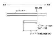
図2に、リングバッファ領域8の状態とTV受信部4から出力されるAVデータを示す。TV受信部4からは、AVデータ14が出力され、現在、現時点15の部分が出力されている。このときリングバッファ領域8には、リングバッファ内のAVデータ16が記録されている。リングバッファ内のAVデータ16は、現時点から30秒分過去に遡った部分までが記録されている。すなわち、30秒過去から現時点15までのAVデータをプレイバック再生することが出来る。この30秒分のAVデータは、図2ではプレイバック再生可能部分17として示されている。
【0078】
視聴者は、このようにしてモニタ3に表示される番組を視聴している。
【0079】
視聴者が視聴している番組が英会話の番組であるとする。そして、英会話を暗記するために英会話の一部分を繰り返して視聴したい思ったとする。このような場合、視聴者は、プレイバック再生を行う。
【0080】
次に、プレイバック再生を行う際の動作を説明する。
【0081】
英会話の一部を繰り返し視聴するために、視聴者は、図3に示すリモコン18のプレイバック19のキーを押す。
【0082】
そうすると、システム制御部11は、リモコン18からの操作命令を受信する。次に、システム制御部11は、TV受信部4から送られてくるAVデータを再生部12に中継する側からリングバッファ領域8のAVデータを再生部12に中継するように切替スイッチ10を切り替える。同時に録画制御部5にプレイバック再生を開始することを通知する。
【0083】
録画制御部5は、これを受けて、プレイバック再生中はリングバッファ領域8にAVデータを書き込むことを中止し、30秒経過したAVデータを消去することも中止する。このように録画制御部5は、プレイバック再生中はリングバッファ領域8を凍結する。
【0084】
再生部12は、リングバッファ領域8のAVデータを読み込み、デコードしてアナログ信号に変換する。
【0085】
モニタ3は、アナログ信号の映像と音声を表示する。
【0086】
視聴者は、このようにしてプレイバック再生された繰り返し視聴したい英会話の部分を再度視聴することができる。
【0087】
さらに、プレイバック再生中に視聴者は、リモコン18の全部保存20のキーを押したとする。
【0088】
そうすると、システム制御部11は、リモコン18からの操作命令を受信する。次に、システム制御部11は、録画制御部5にリングバッファ領域8に記録されているAVデータを保存領域9にコピーするように命じる。
【0089】
これを受けて、録画制御部5は、リングバッファ領域8に記録されているAVデータを保存領域9にコピーする。プレイバック再生中、録画制御部5は、リングバッファ領域8へ新たにAVデータを記録せず、またAVデータを消去しないので、録画制御部5は、視聴者が繰り返し視聴したい英会話の部分を30秒分保存領域9に書き込むことが出来る。
【0090】
このように保存領域9に記録されたAVデータは恒久的に保存されるので、何度も繰り返して再生することが出来る。
【0091】
プレイバック再生を開始してから30秒経過すると、録画制御部5はプレイバック再生が終了したことをシステム制御部11に通知する。さらに、リングバッファ領域8への書き込みと30秒以上経過したAVデータの消去を再開する。
【0092】
システム制御部11は、録画制御部5からの通知を受けて、切替スイッチ10をTV受信部4から出力されたAVデータを再生部12に中継するように指示する。切替スイッチ10は、この指示に従ってTV受信部4から送られてくるAVデータを再生部12に中継する。
【0093】
再生部12は、再びTV受信部4から送られてくるAVデータをデコードしてアナログデータに変換する。
【0094】
そして、モニタ3は、現在放送中の番組を表示する。
【0095】
前述したように保存領域9に保存されたAVデータは、恒久的に保存されるので、視聴者の都合のいい時間に何回でも繰り返し再生して視聴することが出来るが、もちろん、保存領域9に保存されているAVデータのうち不要になったAVデータについては、視聴者がテレビジョン受像装置1の操作パネルまたはリモコン18を操作することによって消去することが出来る。
【0096】
なお、本実施の形態では、英会話の番組を視聴している場合について説明したが、料理番組、映画、ドラマ、野球、相撲、音楽などどのような番組であっても構わない。
【0097】
さらに、本実施の形態では、放送局から送られてくるAVデータがMPEG2トランスポートストリームとして送られてくるとして説明したが、これに限らない。MPEG1準拠のAVデータ、MPEG4準拠のAVデータ、MPEG2プログラムストリーム、あるいはMPEG以外のデータ形式など、要するにディジタルデータとしてAVデータが放送局から送られてきさえすればよい。
【0098】
さらに、本実施の形態では、プレイバック再生の時間は30秒であるとして説明したが、これに限らず、20秒、10秒など、要するにプレイバック再生に適した所定の時間でありさえすればよい。
【0099】
さらに、本実施の形態では、録画制御部5はリングバッファ領域8にAVデータを記録しながら、記録してから所定の時間が経過したAVデータを逐次消去するとして説明したがこれに限らない。録画制御部5はリングバッファ領域8にすでに記録されているAVデータに逐次上書きしていっても構わない。ただし、I、B、Pフレームの違いや映像の複雑さによって1フレームあたりのデータの容量が変化するので、プレイバック再生の再生可能時間にばらつきが生じるが本実施の形態と同等の効果を得ることが出来る。
【0100】
さらに、本実施の形態では、プレイバック再生用のAVデータを記録する領域として、HDD7にリングバッファ領域8を設けたが、これに限らず、半導体メモリ、光磁気ディスクなど、要するに現時点から所定の時間分のAVデータを常に記録しており、現時点から所定時間分のAVデータを出力出来るバッファでありさえすればよい。
【0101】
さらに、本実施の形態では、プレイバック再生中にAVデータをHDD7の保存領域9に恒久的の保存するとして説明したが、これに限らず、TV受信部4からのAVデータを再生している最中にリングバッファ領域8に記録されているAVデータを保存領域9に保存しても構わない。そのためには、放送中のAVデータをモニタに表示している際に、プレイバック19のキーを押さずに、直接リモコン18の全部保存20のキーを押す操作を行えばよい。
【0102】
(第2の実施の形態)
次に、本発明に関連する発明の第2の実施の形態について説明する。
【0103】
図1に本実施の形態のテレビジョン受像装置1を示す。本実施の形態のテレビジョン受像装置1は第1の実施の形態と同一である。
【0104】
また、図3に本実施の形態のリモコン18を示す。本実施の形態のリモコン18も第1の実施の形態と同一である。
【0106】
次に、このような本実施の形態の動作を第1の実施の形態との相違点を中心に説明する。
【0107】
なお、本実施の形態でもAVデータは放送局からMPEG2トランスポートストリームとして送られてくる。
【0108】
本実施の形態でも、英会話の番組を視聴している場合を例にして説明する。現在放送されている英会話の番組を視聴している際の動作は第1の実施の形態と同一である。
【0109】
英会話の単語の発音を練習するために単語の発音練習のシーンを繰り返して視聴したいと思ったとする。このような場合、視聴者は、プレイバック再生を行う。
【0110】
単語の発音練習のシーンを繰り返し視聴するために、視聴者は、図3に示すリモコン18のプレイバック19のキーを押す。
【0111】
そうすると、システム制御部11は、リモコン18からの操作命令を受信する。次に、システム制御部11は、TV受信部4から送られてくるAVデータを再生部12に中継する側からリングバッファ領域8のAVデータを再生部12に中継するように切替スイッチ10を制御する。同時に録画制御部5にプレイバック再生を開始することを通知する。
【0112】
第1の実施の形態とは異なり、録画制御部5は、プレイバック再生中もリングバッファ領域8にAVデータを記録し続けながら記録してから30秒経過したAVデータを消去し続ける。すなわち、リングバッファ領域8を凍結せず、継続してAVデータのバッファリングを行う。
【0113】
再生部12は、リングバッファ領域8のAVデータを読み込み、デコードしてアナログ信号に変換する。
【0114】
モニタ3は、アナログ信号の映像と音声を表示する。
【0115】
視聴者は、このようにして単語の発音練習のシーンを再度視聴することができる。ただし、単語の発音練習のシーンは15秒間のシーンであったとする。
【0116】
このような場合、プレイバック再生していて、単語の発音練習のシーンが始まると、視聴者は、リモコン18の一部保存21のキーを押す。
【0117】
そうすると、システム制御部11は、リモコン18からの操作命令を受信する。次に、システム制御部11は、録画制御部5にリングバッファ領域8に記録されているAVデータのうち現在プレイバック再生されている部分から保存領域9にコピーするように命じる。
【0118】
これを受けて、録画制御部5は、リングバッファ領域8に記録されているAVデータのうち現在再生中の部分を保存領域9にコピーする。
【0119】
単語の発音練習のシーンが終了すると、視聴者は、リモコン18の一部保存21のキーをもう一度押す。
【0120】
そうすると、システム制御部11は、リモコン18からの操作命令を受信する。次に、システム制御部11は、録画制御部5にリングバッファ領域8に記録されているAVデータのうち現在プレイバック再生されている部分を保存領域9にコピーすることを終了するように命じる。
【0121】
これを受けて、録画制御部5は、AVデータのうち現在プレイバック再生されている部分を保存領域9にコピーすることを中止する。
【0122】
保存領域9には、単語の発音練習のシーンのみを保存されている。このように一部保存21のキーで保存開始指示がなされた時にプレイバック再生中の記録エリアの位置から、一部保存21のキーをもう一度押すことにより保存終了指示がなされた時のプレイバック再生中の記録エリアの位置までのAVデータを保存領域9に保存することによって、保存領域9にAVデータのうち必要な部分のみ記録することが出来る。記録されたAVデータは恒久的に保存されるので、何度も繰り返して再生することが出来る。
【0123】
プレイバック再生を開始してから30秒経過すると、録画制御部5はプレイバック再生が終了したことをシステム制御部11に通知する。
【0124】
システム制御部11は、録画制御部5からの通知を受けて、切替スイッチ10をTV受信部4から出力されたAVデータを再生部12に中継するように指示する。切替スイッチ10は、この指示に従ってTV受信部4から送られてくるAVデータを再生部12に中継する。
【0125】
再生部12は、再びTV受信部4から送られてくるAVデータをデコードしてアナログデータに変換する。
【0126】
そして、モニタ3は、現在放送中のAVデータを表示する。
【0127】
保存領域9に保存されたAVデータは、恒久的に保存されるので、視聴者の都合のいい時間に何回でも繰り返し再生して視聴することが出来る。もちろん、保存領域9に保存されているAVデータのうち不要になったAVデータについては、視聴者がテレビジョン受像装置1の操作パネルまたはリモコン18を操作することによって消去することが出来る。
【0128】
なお、本実施の形態では、プレイバック再生中に録画制御部5はリングバッファ領域8の凍結を行わないとして説明したが、これに限らず、プレイバック再生中に録画制御部5はリングバッファ領域8の凍結を行っても構わない。
【0129】
さらに、本実施の形態では、リモコン18の一部保存21のキーを押して、AVデータのうち保存する部分を決定したが、これに限らず、全部保存20のキーを押しても構わない。この場合、録画制御部5は、リングバッファ領域8のうち、まだプレイバック再生が行われていないAVデータの部分を保存領域9に保存する。
【0130】
さらに、本実施の形態では、英会話の番組を視聴している場合について説明したが、料理番組、映画、ドラマ、野球、相撲、音楽などどのような番組であっても構わない。
【0131】
さらに、本実施の形態では、放送局から送られてくるAVデータがMPEG2トランスポートストリームとして送られてくるとして説明したが、これに限らない。MPEG1準拠のAVデータ、MPEG4準拠のAVデータ、MPEG2プログラムストリーム、あるいはMPEG以外のデータ形式など、要するにディジタルデータとしてAVデータが放送局から送られてきさえすればよい。
【0132】
さらに、本実施の形態では、プレイバック再生の時間は30秒であるとして説明したが、これに限らず、20秒、10秒など、要するにプレイバック再生に適した所定の時間でありさえすればよい。
【0133】
さらに、本実施の形態では、録画制御部5はリングバッファ領域8にAVデータを記録しながら、記録してから所定の時間が経過したAVデータを逐次消去するとして説明したがこれに限らない。録画制御部5はリングバッファ領域8にすでに記録されているAVデータに逐次上書きしていっても構わない。ただし、I、B、Pフレームの違いや映像の複雑さによって1フレームあたりのデータの容量が変化するので、プレイバック再生の再生可能時間にばらつきが生じるが本実施の形態と同等の効果を得ることが出来る。
【0134】
さらに、本実施の形態では、プレイバック再生用のAVデータを記録する領域として、HDD7にリングバッファ領域8を設けたが、これに限らず、半導体メモリ、光磁気ディスクなど、要するに現時点から所定の時間分のAVデータを常に記録しており、現時点から所定時間分のAVデータを出力出来るバッファでありさえすればよい。
【0135】
さらに、本実施の形態では、プレイバック再生中にAVデータをHDD7の保存領域9に恒久的に保存するとして説明したが、これに限らず、半導体メモリ、光磁気ディスクなど、要するにAVデータを保存出来る記録媒体に保存しさえすればよい。
【0136】
(第3の実施の形態)
次に、本発明に関連する発明の第3の実施の形態について説明する。
【0137】
図1に本実施の形態のテレビジョン受像装置1を示す。本実施の形態のテレビジョン受像装置1は第1の実施の形態と同一である。
【0138】
また、図3に本実施の形態のリモコン18を示す。本実施の形態のリモコン18も第1の実施の形態と同一である。
【0140】
次に、このような本実施の形態の動作を第1の実施の形態との相違点を中心に説明する。
【0141】
なお、本実施の形態でもAVデータは放送局からMPEG2トランスポートストリームとして送られてくる。
【0142】
本実施の形態では、通信販売の番組を視聴しており、掃除機を購入する場合を例にして説明する。
【0143】
現在放送されている番組を視聴している際の動作は第1の実施の形態と同一である。
【0144】
視聴者が視聴している番組が通信販売の番組であるとする。視聴者は、通信販売の番組で掃除機を紹介するコーナーを視聴し、その掃除機を購入したいと思ったとする。そして、そのコーナーの最後に購入するための電話番号と注文のための製品番号と掃除機の静止画からなる注文の仕方を紹介するシーンが表示されたとする。このような場合、視聴者は、注文するシーンをもう一度視聴するためにプレイバック再生を行う。
【0145】
次に、プレイバック再生を行う際の動作を説明する。
【0146】
購入するための電話番号と製品番号と掃除機の静止画からなる注文の仕方を紹介するシーンを再度視聴するために、視聴者は、図3に示すリモコン18のプレイバック19のキーを押す。また、このシーンは静止画であったする。
【0147】
そうすると、システム制御部11は、リモコン18からの操作命令を受信する。次に、システム制御部11は、TV受信部4から送られてくるAVデータを再生部12に中継する側からリングバッファ領域8のAVデータを再生部12に中継するように切替スイッチ10を切り替える。同時に録画制御部5にプレイバック再生を開始することを通知する。
【0148】
録画制御部5は、これを受けて、プレイバック再生中はリングバッファ領域8にAVデータを書き込むことを中止し、30秒経過したAVデータを消去することも中止する。このように録画制御部5は、プレイバック再生中はリングバッファ領域8を凍結する。
【0149】
再生部12は、リングバッファ領域8のAVデータを読み込み、デコードしてアナログ信号に変換する。
【0150】
モニタ3は、アナログ信号の映像と音声を表示する。
【0151】
視聴者は、このようにしてプレイバック再生された注文の仕方を紹介するシーンを再度視聴することができる。
【0152】
さらに、プレイバック再生中に視聴者は、リモコン18の静止画保存22のキーを押したとする。
【0153】
そうすると、システム制御部11は、リモコン18からの操作命令を受信する。次に、システム制御部11は、録画制御部5にリングバッファ領域8に記録されているAVデータのうちIフレームのみを保存領域9にコピーするように命じる。
【0154】
これを受けて、録画制御部5は、リングバッファ領域8に記録されているAVデータのうちIフレームのみを保存領域9にコピーする。プレイバック再生中、録画制御部5は、リングバッファ領域8へ新たにAVデータを記録せず、またAVデータを消去しないので、録画制御部5は、購入方法を紹介するシーンを保存領域9に書き込むことが出来る。このシーンは静止画であるので、B、Pフレームまで保存する必要がない。
【0155】
このように保存領域9に記録されたAVデータは恒久的に保存されるので、何度も繰り返して再生することが出来る。
【0156】
プレイバック再生を開始してから30秒経過すると、録画制御部5はプレイバック再生が終了したことをシステム制御部11に通知する。さらに、リングバッファ領域8への書き込みと30秒以上経過したAVデータの消去を再開する。
【0157】
システム制御部11は、録画制御部5からの通知を受けて、切替スイッチ10をTV受信部4から出力されたAVデータを再生部12に中継するように指示する。切替スイッチ10は、この指示に従ってTV受信部4から送られてくるAVデータを再生部12に中継する。
【0158】
再生部12は、再びTV受信部4から送られてくるAVデータをデコードしてアナログデータに変換する。
【0159】
そして、モニタ3は、現在放送中の番組を表示する。
【0160】
保存領域9に保存されたAVデータは、恒久的に保存されるので、視聴者の都合のいい時間に何回でも繰り返し再生して視聴することが出来る。もちろん、保存領域9に保存されているAVデータのうち不要になったAVデータについては、視聴者がテレビジョン受像装置1の操作パネルまたはリモコン18を操作することによって消去することが出来る。
【0161】
保存領域9に保存された電話番号と製品番号と掃除機の静止画からなる掃除機を注文するシーンを再生することによって、視聴者は、掃除機のデザインをじっくり確認することが出来、購入するかどうかの判断の材料に使うことが出来る。また、注文するための製品番号や、注文先の電話番号などのメモもとる必要がない。
【0162】
本実施の形態では、静止画のシーンについては、Iフレームのみを保存領域9に保存することによって保存領域9を節約することも出来る。
【0163】
なお、本実施の形態では、通信販売の番組を視聴している場合について説明したが、料理番組、映画、ドラマ、野球、相撲、音楽などどのような番組であっても構わない。
【0164】
さらに、本実施の形態では、放送局から送られてくるAVデータがMPEG2トランスポートストリームとして送られてくるとして説明したが、これに限らない。MPEG1準拠のAVデータ、MPEG4準拠のAVデータ、MPEG2プログラムストリーム、あるいはMPEG以外のデータ形式など、要するにディジタルデータとしてAVデータが放送局から送られてきさえすればよい。
【0165】
さらに、本実施の形態では、プレイバック再生の時間は30秒であるとして説明したが、これに限らず、20秒、10秒など、要するにプレイバック再生に適した所定の時間でありさえすればよい。
【0166】
さらに、本実施の形態では、録画制御部5はリングバッファ領域8にAVデータを記録しながら、記録してから所定の時間が経過したAVデータを逐次消去するとして説明したがこれに限らない。録画制御部5はリングバッファ領域8にすでに記録されているAVデータに逐次上書きしていっても構わない。ただし、I、B、Pフレームの違いや映像の複雑さによって1フレームあたりのデータの容量が変化するので、プレイバック再生の再生可能時間にばらつきが生じるが本実施の形態と同等の効果を得ることが出来る。
【0167】
さらに、本実施の形態では、プレイバック再生用のAVデータを記録する領域として、HDD7にリングバッファ領域8を設けたが、これに限らず、半導体メモリ、光磁気ディスクなど、要するに現時点から所定の時間分のAVデータを常に記録しており、現時点から所定時間分のAVデータを出力出来るバッファでありさえすればよい。
【0168】
さらに、本実施の形態では、プレイバック再生中にAVデータをHDD7の保存領域9に恒久的に保存するとして説明したが、これに限らず、半導体メモリ、光磁気ディスクなど、要するにAVデータを保存出来る記録媒体に保存しさえすればよい。
【0169】
さらに、本実施の形態では、プレイバック再生中にAVデータをHDD7の保存領域9に恒久的に保存するとして説明したが、これに限らず、TV受信部4からのAVデータを再生している最中にリングバッファ領域8に記録されているAVデータを保存領域9に保存しても構わない。そのためには、放送中のAVデータをモニタに表示している際に、リモコン18の静止画保存22のキーを押す操作を行えばよい。
【0170】
(第4の実施の形態)
次に、本発明の第4の実施の形態について説明する。
【0171】
本実施の形態では、プレイバック再生用のAVデータを記録するリングバッファ領域が二つある場合について説明する。
【0172】
図4に本実施の形態のテレビジョン受像装置23を示す。本実施の形態のテレビジョン受像装置23は、リングバッファ領域8a、リングバッファ領域8bを二つ持つ。また、録画制御部24、切替スイッチ25が第1の実施の形態とは異なっている。
【0173】
また、図6に本実施の形態のリモコン18を示す。本実施の形態のリモコン18は第1の実施の形態のリモコン18のキーに加えて、長く34、短く35のキーを備えている。
【0174】
録画制御部24は、第1の実施の形態と同じくAVデータをHDD7に記録する手段であり、録画制御部5との相違点は、リングバッファ領域8aとリングバッファ領域8bとに同時にAVデータを記録する並列型の記録と、リングバッファ領域8aとリングバッファ領域8bとをあたかも一つのリングバッファ領域であるようにAVデータを記録する直列型の記録とを行うことが出来る。
【0175】
また、切替スイッチ25は、TV受信部4、リングバッファ領域8a、リングバッファ領域8b、保存領域9のAVデータのいずれから再生部12がAVデータを読み込むかを切り替えるスイッチである。
【0176】
なお、本実施の形態のTV受信部4は本発明の受信手段の例であり、本実施の形態の切り替えスイッチ25、再生部12は本発明の再生手段の例であり、本実施の形態の録画制御部24とリングバッファ領域8a、リングバッファ領域8bは本発明のバッファ手段の例であり、本実施の形態の録画制御部24と保存領域9は本発明の保存手段の例である。
【0177】
次に、このような本実施の形態の動作を第1の実施の形態との相違点を中心に説明する。
【0178】
なお、本実施の形態でもAVデータは放送局からMPEG2トランスポートストリームとして送られてくる。
【0179】
まず、リングバッファ領域8aとリングバッファ領域8bに並列してAVデータを記録する場合の動作について説明する。
【0180】
この場合、録画制御部24は、TV受信部4からMPEG2トランスポートストリームとして送られてくるAVデータを、リングバッファ領域8aとリングバッファ領域8bとに同時に記録する。
【0181】
録画制御部24がリングバッファ領域8aにAVデータを記録する動作と録画制御部24がリングバッファ領域8bにAVデータを記録する動作はそれぞれ第1の実施の形態で録画制御部5がリングバッファ領域8にAVデータを記録する動作と同一である。このように、録画制御部24とリングバッファ領域8aとリングバッファ領域8bは、並列に接続された二つのバッファとして機能する。
【0182】
視聴者が、図6の短く35のキーを押せば、テレビジョン受像装置23は、上記の動作を行う。
【0183】
図5の(a)にリングバッファ領域8aとリングバッファ領域8bの状態であるリングバッファ内のAVデータとTV受信部4から出力されるAVデータを示す。TV受信部4からは、AVデータ14が出力され、現在、現時点15の部分が出力されている。このときリングバッファ領域8aとリングバッファ領域8bには、リングバッファ内のAVデータ16が記録されている。リングバッファ内のAVデータ16は、現時点から30秒分過去に遡った部分までが記録されている。すなわち、30秒過去から現時点15までのAVデータをプレイバック再生することが出来る。この30秒分のAVデータは、図5ではプレイバック再生可能部分17として示されている。すなわち、リングバッファ領域8aとリングバッファ領域8bには同じAVデータが記録されている。
【0184】
モニタ13には、TV受信部4から送られてくる現在放送中のAVデータが表示されている。
【0185】
ここで、視聴者が、リモコン30のプレイバック19のキーを押したとする。
【0186】
そうすると、システム制御部11は、リモコン30からの操作命令を受信する。次に、システム制御部11は、TV受信部4から送られてくるAVデータを再生部12に中継する側からリングバッファ領域8aのAVデータを再生部12に中継するように切替スイッチ25を切り替えるよう制御する。同時に録画制御部24にプレイバック再生を開始することを通知する。
【0187】
録画制御部24は、これを受けて、プレイバック再生中はリングバッファ領域8aにAVデータを書き込むことを中止し、30秒経過したAVデータを消去することも中止する。このように録画制御部24は、プレイバック再生中はリングバッファ領域8aを凍結する。
【0188】
一方、録画制御部24は、リングバッファ領域8bには、AVデータを逐次記録しながら、同時に記録されてから30秒経過したAVデータを消去するバッファリングを継続して行っている。
【0189】
再生部12は、リングバッファ領域8aのAVデータを読み込み、デコードしてアナログ信号に変換する。
【0190】
モニタ13は、アナログ信号の映像と音声を表示する。
【0191】
このようにプレイバック再生している際に、視聴者がさらに、リモコン30のプレイバック19のキーを押したとする。
【0192】
そうすると、システム制御部11は、リモコン30からの操作命令を受信する。
【0193】
システム制御部11は、リングバッファ領域8aに記録されているAVデータを再生部12に中継する側からリングバッファ領域8bのAVデータを再生部12に中継する側に切替スイッチ25を切り替える。同時に録画制御部24にプレイバック再生を開始することを通知する。
【0194】
録画制御部24は、これを受けて、プレイバック再生中はリングバッファ領域8bにAVデータを書き込むことを中止し、30秒経過したAVデータを消去することも中止する。このように録画制御部24は、プレイバック再生中はリングバッファ領域8bを凍結する。
【0195】
一方、録画制御部24は、リングバッファ領域8aには、AVデータを逐次記録しながら、同時に記録されてから30秒経過したAVデータを消去するバッファリングを再開する。
【0196】
このように、プレイバック再生中に放送されたAVデータは、プレイバック再生されていない方のリングバッファ領域8bに記録されているので、リングバッファ領域8aまたは8bを切り替えることによって、プレイバック再生中に放送されたAVデータも視聴することが出来る。
【0197】
また、第1〜第3の実施の形態で説明したように、現在プレイバック再生に用いられているリングバッファ領域8aまたはリングバッファ領域8bに記録されているAVデータを保存領域9に、全部保存したり、指定された部分を保存したり、Iフレームのみ保存したりすることが出来る。
【0198】
次に、リングバッファ領域8aとリングバッファ領域8bを直列型にしてAVデータを記録する場合の動作について説明する。
【0199】
この場合、録画制御部24は、TV受信部4からMPEG2トランスポートストリームとして送られてくるAVデータを、リングバッファ領域8aとリングバッファ領域8bとに順次記録する。
【0200】
その記録の仕方は、リングバッファ領域8aとリングバッファ領域8bがあたかも一つのリングバッファ領域8であるかのように記録する。
【0201】
すなわち、録画制御部24がリングバッファ領域8aとリングバッファ領域8bにAVデータを記録する動作は、第1の実施の形態で録画制御部5がリングバッファ領域8にAVデータを記録する動作と同一である。このように、録画制御部24とリングバッファ領域8aとリングバッファ領域8bは、直列に接続された二つのバッファとして機能する。ただし、リングバッファ領域が並列型に比較して倍の長さになっている。
【0202】
図5の(b)にリングバッファ領域8aとリングバッファ領域8bがあたかも一つのリングバッファ領域であるかのように機能する場合のリングバッファ内のAVデータとTV受信部4から出力されるAVデータを示す。TV受信部4からは、AVデータ14が出力され、現在、現時点15の部分が出力されている。このときリングバッファ領域8aとリングバッファ領域8bには、リングバッファ内のAVデータ32が記録されている。リングバッファ内のAVデータ32は、現時点から60秒分過去に遡った部分までが記録されている。すなわち、60秒過去から現時点15までのAVデータをプレイバック再生することが出来る。この60秒分のAVデータは、図5の(b)ではプレイバック再生可能部分33として示されている。すなわち上述したように、図5の(a)の場合に比較して図5の(b)ではプレイバック再生の時間が倍になる。
【0203】
視聴者が、図6の長く34のキーを押せば、テレビジョン受像装置23は、上記の動作を行う。
【0204】
モニタ13には、TV受信部4から送られてくる現在放送中のAVデータが表示されている。
【0205】
ここで、視聴者が、リモコン30のプレイバック19のキーを押したとする。
【0206】
そうすると、システム制御部11は、リモコン30からの操作命令を受信する。次に、システム制御部11は、TV受信部4から送られてくるAVデータを再生部12に中継する側からリングバッファ領域8aのAVデータを再生部12に中継するように切替スイッチ25を切り替える。同時に録画制御部24にプレイバック再生を開始することを通知する。
【0207】
録画制御部24は、これを受けて、プレイバック再生中はリングバッファ領域8aとリングバッファ領域8bにAVデータを書き込むことを中止する。60秒経過したAVデータを消去することも中止する。このように録画制御部24は、プレイバック再生中はリングバッファ領域8aとリングバッファ領域8bを凍結する。
【0208】
再生部12は、リングバッファ領域8aのAVデータを読み込み、デコードしてアナログ信号に変換する。
【0209】
また、リングバッファ領域8aに記録されているAVデータを再生し終わると、システム制御部11は、切替スイッチ25をリングバッファ領域8bの方に切り替えるように制御する。これを受けて切替スイッチ25は、リングバッファ領域8bから再生部12にAVデータを中継するように切り替える。
【0210】
再生部12は引き続きリングバッファ領域8bに記録されているAVデータを読み込み、デコードしてアナログ信号に変換する。
【0211】
モニタ13は、アナログ信号の映像と音声を表示する。
【0212】
この場合、プレイバック再生中に、視聴者がさらに、リモコン30のプレイバック19のキーを押した場合、再生部12は、もう一度60秒前からプレイバック再生を繰り返す。
【0213】
また、第1〜第3の実施の形態で説明したように、現在プレイバック再生に用いられているリングバッファ領域8aとリングバッファ領域8bに記録されているAVデータを保存領域9に、全部保存したり、指定された部分を保存したり、Iフレームのみ保存したりすることが出来る。
【0214】
このように、テレビジョン受像装置23は、リングバッファ領域8aとリングバッファ領域8bへAVデータを記録する仕方を変更することによって、プレイバック再生中に放送されたため視聴出来なかった部分のAVデータを視聴可能としたり、プレイバック再生の時間を長くするなど、多様なプレイバック再生を行うことが出来る。
【0215】
なお本実施の形態ではリングバッファ領域が二つあるとして説明したが、これに限らず、3個、4個など、要するに複数のリングバッファ領域を備えていさえすればよい。
【0216】
(第5の実施の形態)
次に、本発明に関連する発明の第5の実施の形態について説明する。
【0217】
本実施の形態では、第1〜3の各実施の形態とは異なり放送局から送られてくるAVデータがアナログデータとして送られてくる場合を説明する。
【0218】
図7に本実施の形態のテレビジョン受像装置36の構成を示す。
【0219】
本実施の形態のテレビジョン受像装置36はエンコーダ37を備えている。
【0220】
TV受信部4は、放送局からアナログデータとして送られてくるAVデータを受信し、復調する手段である。
【0221】
エンコーダ37は、TV受信部4で復調されたAVデータをMPEG2トランスポートストリームにエンコードする手段である。
【0222】
次に、このような本実施の形態の動作を説明する。
【0223】
放送局からは、アナログデータとして放送波にのせてAVデータが送られてくる。
【0224】
TV受信部4は、放送波を受信し、復調する。
【0225】
エンコーダ37は、復調されたアナログデータをMPEG2トランスポートストリームにエンコードする。
【0226】
これ以降は、第1〜3の各実施の形態と同一の動作をするので、説明を省略する。
【0227】
このように本実施の形態によれば、第1〜3の各実施の形態で行っていた処理をエンコーダ37を備えることにより、アナログデータに対しても行うことが出来る。
【0228】
(第6の実施の形態)
次に、本発明の第6の実施の形態について説明する。
【0229】
本実施の形態では、第4の実施の形態とは異なり放送局から送られてくるAVデータがアナログデータとして送られてくる場合を説明する。
【0230】
図8に本実施の形態のテレビジョン受像装置38の構成を示す。
【0231】
本実施の形態のテレビジョン受像装置38はエンコーダ37を備えている。
【0232】
TV受信部4は、放送局からアナログデータとして送られてくるAVデータを受信し、復調する手段である。
【0233】
エンコーダ37は、TV受信部4で復調されたAVデータをMPEG2トランスポートストリームにエンコードする手段である。
【0234】
次に、このような本実施の形態の動作を説明する。
【0235】
放送局からは、アナログデータとして放送波にのせてAVデータが送られてくる。
【0236】
TV受信部4は、放送波を受信し、復調する。
【0237】
エンコーダ37は、復調されたアナログデータをMPEG2トランスポートストリームにエンコードする。
【0238】
これ以降は、第4の実施の形態と同一の動作をするので、説明を省略する。
【0239】
このように本実施の形態によれば、第4の実施の形態で行っていた処理をエンコーダ37を備えることにより、アナログデータに対しても行うことが出来る。
【0240】
なお、本発明のテレビジョン受像装置の全部または一部の手段の機能をコンピュータのプログラムによってソフトウェア的に実現しても構わないし、ハードウェアによって実現しても構わない。
【0241】
さらに、本発明のテレビジョン受像装置の全部または一部の手段の機能をコンピュータにより実行させるためのプログラムを記録したプログラム記録媒体であって、コンピュータにより読み取り可能であり、読み取られた前記プログラムが前記コンピュータと協動して前記機能を実行することを特徴とするプログラム記録媒体も本発明に属する。
【0242】
【発明の効果】
以上説明したところから明らかなように、本発明は、プレイバック再生したAVデータを何度も視聴することが出来るテレビジョン受像装置及びプログラム記録媒体を提供することが出来る。
【0243】
また、本発明は、プレイバック中に放送されたAVデータの部分も視聴することが出来るテレビジョン受像装置及びプログラム記録媒体を提供することが出来る。
【0244】
また、本発明は、プレイバック再生を行う時間を長くすることが出来るテレビジョン受像装置及びプログラム記録媒体を提供することが出来る。
【図面の簡単な説明】
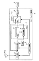
【図1】本発明に関連する発明の第1〜3の実施の形態におけるテレビジョン受像装置の構成を示すブロック図
【図2】本発明に関連する発明の第1〜3の実施の形態におけるAVデータのうちプレイバック再生可能部分を説明する図
【図3】本発明に関連する発明の第1〜3の実施の形態におけるテレビジョン受像装置を操作するリモコンの操作キーを示す図
【図4】本発明の第4の実施の形態におけるテレビジョン受像装置の構成を示すブロック図
【図5】(a)本発明の第4の実施の形態におけるAVデータのうち並列型でリングバッファ領域を使用する場合のプレイバック再生可能部分を説明する図
(b)本発明の第4の実施の形態におけるAVデータのうち直列型でリングバッファ領域を使用する場合のプレイバック再生可能部分を説明する図
【図6】本発明の第4の実施の形態におけるテレビジョン受像装置を操作するリモコンの操作キーを示す図
【図7】本発明に関連する発明の第5の実施の形態におけるテレビジョン受像装置の構成を示すブロック図
【図8】本発明の第6の実施の形態におけるテレビジョン受像装置の構成を示すブロック図
【図9】従来のテレビジョン受像装置の構成を示すブロック図
【符号の説明】
1 テレビジョン受像装置
2 アンテナ
3 モニタ
4 TV受信部
5 録画制御部
6 時計
7 HDD
8 リングバッファ領域
9 保存領域
10 切替スイッチ
11 システム制御部
12 再生部
14 AVデータ
15 現時点
16 リングバッファ内のAVデータ
17 プレイバック再生可能部分
18 リモコン
19 プレイバック
20 全部保存
21 一部保存
22 静止画保存
23 テレビジョン受像装置
24 録画制御部
25 切替スイッチ
26 テレビジョン受像装置
27 録画制御部
28 リングバッファ領域
29 切替スイッチ[0001]
BACKGROUND OF THE INVENTION
The present invention relates to a television receiver and a program recording medium capable of performing playback reproduction for viewing again a video that has been viewed while viewing a real-time video such as a television broadcast.
[0002]
[Prior art]
When viewing a real-time video such as a television broadcast, if there is a desire to view a part that has been viewed again, there is a television receiver having a playback function called playback that simply and quickly reproduces the part that has been viewed.
[0003]
Hereinafter, such a
[0004]
The
[0005]
In addition, an antenna 2 and a
[0006]
The antenna 2 is means for converting a broadcast wave transmitted from a broadcast station into an electric signal.
[0007]
The TV receiving
[0008]
The
[0009]
The
[0010]
The
[0011]
The
[0012]
The changeover switch 29 inputs AV data sent from the
[0013]
The
[0014]
The
[0015]
The
[0016]
Next, the operation of such a
[0017]
The antenna 2 converts a broadcast wave transmitted from a broadcast station into an electric signal.
[0018]
The
[0019]
The changeover switch 29 is switched to input AV data sent from the
[0020]
The
[0021]
On the other hand, the
[0022]
Since the change-over switch 29 is switched so that AV data is sent from the
[0023]
The viewer views the video and audio displayed on the
[0024]
An operation command from the remote controller is notified to the
[0025]
That is, the changeover switch 29 is changed over so that the
[0026]
The
[0027]
The viewer can view the cooking recipe again by such playback reproduction.
[0028]
When the reproduction of the AV data for 30 seconds is completed, the
[0029]
The
[0030]
As described above, by simply pressing the operation button on the remote controller, video and audio can be played back 30 seconds in the past.
[0031]
[Problems to be solved by the invention]
However, in the
[0032]
Also, the program is continuously broadcast during playback, but when playback is completed, it is played back from the AV data broadcast when playback is completed, so it was broadcast during playback. The AV data part cannot be viewed. That is, the conventional television apparatus has a problem that the AV data broadcast during playback cannot be viewed.
[0033]
Further, since the playback time is determined by the size of the buffer for recording AV data for playback, the playback time cannot be lengthened. That is, the conventional television receiver has a problem that it is not possible to lengthen the playback time.
[0034]
The present invention takes into consideration the problem that the playback-reproduced AV data cannot be further viewed in the conventional television receiver, and the television image can be viewed many times. An object is to provide an apparatus and a program recording medium.
[0035]
In addition, the present invention takes into consideration the problem that a conventional television apparatus cannot view a portion of AV data broadcasted during playback, and a portion of AV data broadcast during playback is also viewed. An object of the present invention is to provide a television receiver and a program recording medium that can be used.
[0036]
Further, the present invention takes into consideration the problem that in the conventional television receiver, the time for performing playback reproduction cannot be increased, and the television receiver capable of extending the time for performing playback reproduction, and It is an object to provide a program recording medium.
[0037]
[Means for solving the problems]]
[0048]
In order to solve the problems described above, the firstThe present invention isReceiving means for receiving transmitted AV data;
A plurality of buffer means for sequentially buffering the received AV data and performing buffering for sequentially erasing the AV data after a predetermined time has elapsed since recording simultaneously;
A reproduction means for performing normal reproduction for reproducing the received AV data or playback reproduction for reproducing the AV data for the predetermined time recorded in the buffer means;
When receiving the instruction, the playback means switches between performing the normal playback or the playback playback,
Upon receiving the instruction, the plurality of buffer means can be switched between being connected in series with the receiving means or being connected in parallel,
When the plurality of buffer means are connected in parallel with the receiving means, the playback means is performing the playback playback using any one of the plurality of buffer means. The other buffer means performs the buffering on the AV data,
When the plurality of buffer means are connected in series with the receiving means, the plurality of buffer means function as one buffer means, and the playback playback time is connected in parallel. It is characterized by being longer thanTeRevision receiver.
[0049]
Also,SecondThe present invention comprises storage means for storing the AV data recorded in the plurality of buffer means,
When receiving the instruction, the storage means stores the AV data recorded in the buffer means.1'sIt is a television receiver of the present invention.
Also,ThirdIn the present invention, the AV data is sent as analog data,
Encoder means for converting the received AV data into digital data;
The buffer means performs the buffering on the AV data converted into the digital data.Or secondThis is a television receiver of the present invention.
[0050]
Also,4thThe present invention relates to a receiving means for receiving AV data sent from the television receiver of the first present invention,
A plurality of buffer means for sequentially buffering the received AV data, and performing buffering for sequentially erasing the AV data after a predetermined time has elapsed since the simultaneous recording;
A program recording a program for causing a computer to function as playback means for performing normal playback for playing back the received AV data, or playback playback for playing back the AV data for the predetermined time recorded in the buffer means A recording medium is a program recording medium that can be processed by a computer.
[0051]
DETAILED DESCRIPTION OF THE INVENTION
In the following, the present inventionAnd inventions related to the present inventionThe embodiment will be described with reference to the drawings.
[0052]
(First embodiment)
First,Of the invention related to the present inventionA first embodiment will be described.
[0053]
FIG. 1 is a block diagram showing a configuration of the television receiver 1 according to the present embodiment.
[0054]
The television receiver 1 includes a
[0055]
Further, an antenna 2 and a
[0056]
The antenna 2 is means for converting a broadcast wave transmitted from a broadcast station into an electric signal.
[0057]
FIG. 3 shows the remote controller 18 of the present embodiment. The remote controller 18 includes keys for playback 19, save all 20, save
[0058]
The
[0059]
The
[0060]
The
[0061]
The
[0062]
The
[0063]
The
[0064]
The changeover switch 10 sends AV data sent from the
[0065]
The
[0066]
The
[0067]
The
[0069]
Next, the operation of this embodiment will be described.
[0070]
First, the operation when viewing a program broadcast on a broadcasting station will be described.
[0071]
From the broadcasting station, AV data is sent as an MPEG2 transport stream on a broadcast wave.
[0072]
The antenna 2 converts this broadcast wave into an electric signal.
[0073]
The
[0074]
It is assumed that the changeover switch 10 is set to relay AV data transmitted from the
[0075]
The
[0076]
On the other hand, the
[0077]
FIG. 2 shows the state of the
[0078]
The viewer views the program displayed on the
[0079]
It is assumed that the program that the viewer is watching is an English conversation program. Suppose you want to watch a part of an English conversation repeatedly to memorize it. In such a case, the viewer performs playback playback.
[0080]
Next, an operation when performing playback reproduction will be described.
[0081]
In order to repeatedly view a part of the English conversation, the viewer presses the key of the playback 19 of the remote controller 18 shown in FIG.
[0082]
Then, the
[0083]
In response to this, the
[0084]
Playback unit 12Reads the AV data in the
[0085]
The
[0086]
The viewer can view again the portion of the English conversation that he / she wants to view repeatedly, thus reproduced.
[0087]
Furthermore, it is assumed that the viewer presses the save all 20 key on the remote control 18 during playback.
[0088]
Then, the
[0089]
In response to this, the
[0090]
Since the AV data recorded in the
[0091]
When 30 seconds have elapsed after starting playback, the
[0092]
In response to the notification from the
[0093]
The reproducing
[0094]
The
[0095]
As described above, since the AV data stored in the
[0096]
In this embodiment, the case where an English conversation program is viewed has been described. However, any program such as a cooking program, a movie, a drama, baseball, a sumo, or music may be used.
[0097]
Furthermore, in the present embodiment, it has been described that AV data transmitted from a broadcasting station is transmitted as an MPEG2 transport stream, but the present invention is not limited to this. It is only necessary that the AV data is sent from the broadcasting station as digital data such as MPEG1 compliant AV data, MPEG4 compliant AV data, MPEG2 program stream, or a data format other than MPEG.
[0098]
Furthermore, in the present embodiment, the playback playback time has been described as being 30 seconds. However, the playback playback time is not limited to this, and as long as the playback playback time is a predetermined time suitable for playback playback, such as 20 seconds or 10 seconds. Good.
[0099]
Furthermore, in the present embodiment, the
[0100]
Further, in the present embodiment, the
[0101]
Furthermore, in the present embodiment, it has been described that AV data is permanently stored in the
[0102]
(Second Embodiment)
next,Of the invention related to the present inventionA second embodiment will be described.
[0103]
FIG. 1 shows a television receiver 1 according to the present embodiment. The television receiver 1 of the present embodiment is the same as that of the first embodiment.
[0104]
FIG. 3 shows the remote controller 18 of the present embodiment. The remote controller 18 of the present embodiment is the same as that of the first embodiment.
[0106]
Next, the operation of the present embodiment will be described focusing on the differences from the first embodiment.
[0107]
In this embodiment as well, AV data is sent from the broadcast station as an MPEG2 transport stream.
[0108]
Also in this embodiment, a case where an English conversation program is viewed will be described as an example. The operation when viewing an English conversation program currently being broadcast is the same as in the first embodiment.
[0109]
Watched repeated practice of pronunciation of words to practice pronunciation of English conversation wordsItoSuppose you thought. In such a case, the viewer performs playback playback.
[0110]
In order to repeatedly view the word pronunciation practice scene, the viewer presses the key of the playback 19 of the remote controller 18 shown in FIG.
[0111]
Then, the
[0112]
Unlike the first embodiment, the
[0113]
Playback unit 12Reads the AV data in the
[0114]
The
[0115]
In this way, the viewer can view the word pronunciation practice scene again. However, it is assumed that the word pronunciation practice scene is a 15-second scene.
[0116]
In such a case, when playback is being played back and a scene of word pronunciation practice begins, the viewer presses the key of the partial save 21 of the remote controller 18.
[0117]
Then, the
[0118]
In response to this, the
[0119]
When the word pronunciation practice scene is completed, the viewer presses the partial save 21 key of the remote controller 18 again.
[0120]
Then, the
[0121]
In response to this, the recording control unit5Stops copying the portion of the AV data currently being played back to the
[0122]
In the
[0123]
When 30 seconds have elapsed after starting playback, the
[0124]
In response to the notification from the
[0125]
The reproducing
[0126]
The
[0127]
Since the AV data stored in the
[0128]
In this embodiment, the pre-IAlthough it has been described that the
[0129]
Further, in the present embodiment, the part of the AV data to be saved is determined by pressing the partial save 21 key of the remote controller 18. In this case, the
[0130]
Furthermore, although the case where an English conversation program is viewed has been described in the present embodiment, any program such as a cooking program, a movie, a drama, baseball, sumo, or music may be used.
[0131]
Furthermore, in the present embodiment, it has been described that AV data transmitted from a broadcasting station is transmitted as an MPEG2 transport stream, but the present invention is not limited to this. It is only necessary that the AV data is sent from the broadcasting station as digital data such as MPEG1 compliant AV data, MPEG4 compliant AV data, MPEG2 program stream, or a data format other than MPEG.
[0132]
Furthermore, in the present embodiment, the playback playback time has been described as being 30 seconds. However, the playback playback time is not limited to this, and as long as the playback playback time is a predetermined time suitable for playback playback, such as 20 seconds or 10 seconds. Good.
[0133]
Furthermore, in the present embodiment, the
[0134]
Further, in the present embodiment, the
[0135]
Furthermore, in the present embodiment, it has been described that AV data is permanently stored in the
[0136]
(Third embodiment)
next,Of the invention related to the present inventionA third embodiment will be described.
[0137]
FIG. 1 shows a television receiver 1 according to the present embodiment. The television receiver 1 of the present embodiment is the same as that of the first embodiment.
[0138]
FIG. 3 shows the remote controller 18 of the present embodiment. The remote controller 18 of the present embodiment is the same as that of the first embodiment.
[0140]
Next, the operation of the present embodiment will be described focusing on the differences from the first embodiment.
[0141]
In this embodiment as well, AV data is sent from the broadcast station as an MPEG2 transport stream.
[0142]
In this embodiment, a case where a mail order program is viewed and a cleaner is purchased will be described as an example.
[0143]
The operation when viewing a currently broadcast program is the same as in the first embodiment.
[0144]
It is assumed that the program being viewed by the viewer is a mail order program. A viewer views a corner introducing a vacuum cleaner on a mail-order program and wants to purchase the vacuum cleaner. Then, at the end of the corner, it is assumed that a scene is displayed that introduces an ordering method including a telephone number for purchase, a product number for ordering, and a still image of a vacuum cleaner. In such a case, the viewer performs playback playback in order to view the scene to be ordered again.
[0145]
Next, an operation when performing playback reproduction will be described.
[0146]
In order to view again the scene introducing the ordering method including the telephone number, the product number, and the still image of the vacuum cleaner for purchase, the viewer presses the key of the playback 19 of the remote controller 18 shown in FIG. Also, this scene is a still image.
[0147]
Then, the
[0148]
In response to this, the
[0149]
Playback unit 12Reads the AV data in the
[0150]
The
[0151]
The viewer can view again the scene that introduces the method of ordering played back in this way.
[0152]
Furthermore, it is assumed that the viewer presses the
[0153]
Then, the
[0154]
In response to this, the
[0155]
Since the AV data recorded in the
[0156]
When 30 seconds have elapsed after starting playback, the
[0157]
In response to the notification from the
[0158]
The reproducing
[0159]
The
[0160]
Since the AV data stored in the
[0161]
By playing a scene to order a vacuum cleaner consisting of the phone number, product number, and the still image of the vacuum cleaner stored in the
[0162]
In the present embodiment, for a still image scene, the
[0163]
In the present embodiment, the case where a mail-order program is viewed has been described, but any program such as a cooking program, a movie, a drama, baseball, a sumo, or music may be used.
[0164]
Furthermore, in the present embodiment, it has been described that AV data transmitted from a broadcasting station is transmitted as an MPEG2 transport stream, but the present invention is not limited to this. It is only necessary that the AV data is sent from the broadcasting station as digital data such as MPEG1 compliant AV data, MPEG4 compliant AV data, MPEG2 program stream, or a data format other than MPEG.
[0165]
Furthermore, in the present embodiment, the playback playback time has been described as being 30 seconds. However, the playback playback time is not limited to this, and as long as the playback playback time is a predetermined time suitable for playback playback, such as 20 seconds or 10 seconds. Good.
[0166]
Furthermore, in the present embodiment, the
[0167]
Further, in the present embodiment, the
[0168]
Furthermore, in the present embodiment, it has been described that AV data is permanently stored in the
[0169]
Furthermore, in this embodiment, AV data is permanently stored in the
[0170]
(Fourth embodiment)
next,Of the present inventionA fourth embodiment will be described.
[0171]
In the present embodiment, a case will be described in which there are two ring buffer areas for recording AV data for playback reproduction.
[0172]
FIG. 4 shows a
[0173]
FIG. 6 shows the remote controller 18 of the present embodiment. The remote controller 18 of the present embodiment is provided with 34 long and 35 short keys in addition to the keys of the remote controller 18 of the first embodiment.
[0174]
The
[0175]
Further, the changeover switch 25 is a switch for switching from among the AV data in the
[0176]
The
[0177]
Next, the operation of the present embodiment will be described focusing on the differences from the first embodiment.
[0178]
In this embodiment as well, AV data is sent from the broadcast station as an MPEG2 transport stream.
[0179]
First, an operation when AV data is recorded in parallel in the
[0180]
In this case, the
[0181]
The
[0182]
If the viewer presses the short key 35 in FIG. 6, the
[0183]
FIG. 5A shows the AV data in the ring buffer in the state of the
[0184]
On the
[0185]
Here, it is assumed that the viewer presses the playback 19 key of the remote controller 30.
[0186]
Then, the
[0187]
In response to this, the
[0188]
On the other hand, the
[0189]
The reproducing
[0190]
monitor13Displays analog video and audio.
[0191]
Assume that the viewer further presses the key of the playback 19 of the remote controller 30 during playback playback in this way.
[0192]
Then, the
[0193]
The
[0194]
In response to this, the
[0195]
On the other hand, the
[0196]
In this way, AV data broadcast during playback is not replayed on the side that is not being played back.NgSince it is recorded in the
[0197]
Further, as described in the first to third embodiments, all AV data recorded in the
[0198]
Next, the operation in the case of recording AV data with the
[0199]
In this case, the
[0200]
The recording is performed as if the
[0201]
That is, the operation in which the
[0202]
AV data in the ring buffer and AV data output from the
[0203]
The viewer is long in FIG.34When the key is pressed, the
[0204]
On the
[0205]
Here, it is assumed that the viewer presses the playback 19 key of the remote controller 30.
[0206]
Then, the
[0207]
In response to this, the
[0208]
Playback unit 12Reads the AV data in the
[0209]
When the AV data recorded in the
[0210]
The reproducing
[0211]
monitor13Displays analog video and audio.
[0212]
In this case, when the viewer further presses the key of the playback 19 of the remote controller 30 during playback, the
[0213]
Further, as described in the first to third embodiments, all the AV data recorded in the
[0214]
In this way, the
[0215]
Although the present embodiment has been described on the assumption that there are two ring buffer areas, the present invention is not limited to this, and it is sufficient to provide a plurality of ring buffer areas such as three or four.
[0216]
(Fifth embodiment)
next,Of the invention related to the present inventionA fifth embodiment will be described.
[0217]
In this embodiment, unlike the first to third embodiments, a case will be described in which AV data sent from a broadcasting station is sent as analog data.
[0218]
FIG. 7 shows the configuration of the
[0219]
The
[0220]
The
[0221]
The
[0222]
Next, the operation of this embodiment will be described.
[0223]
From the broadcasting station, AV data is transmitted as analog data on a broadcast wave.
[0224]
The
[0225]
The
[0226]
Thereafter, the same operations as those in the first to third embodiments are performed, and thus the description thereof is omitted.
[0227]
As described above, according to the present embodiment, the processing performed in the first to third embodiments can be performed on analog data by providing the
[0228]
(Sixth embodiment)
next,Of the present inventionA sixth embodiment will be described.
[0229]
In the present embodiment, unlike the fourth embodiment, a case will be described in which AV data sent from a broadcasting station is sent as analog data.
[0230]
FIG. 8 shows a configuration of the
[0231]
The
[0232]
The
[0233]
The
[0234]
Next, the operation of this embodiment will be described.
[0235]
From the broadcasting station, AV data is transmitted as analog data on a broadcast wave.
[0236]
The
[0237]
The
[0238]
Subsequent operations are the same as those in the fourth embodiment, and a description thereof will be omitted.
[0239]
Thus, according to the present embodiment, the processing performed in the fourth embodiment can be performed on analog data by providing the
[0240]
It should be noted that all or part of the television receiver of the present invention is used.SteppedThe function may be realized by software by a computer program or may be realized by hardware.
[0241]
Further, all or some of the hands of the television receiver of the present invention.SteppedProgram to execute functions by computerTheA recorded program recording medium, readable by a computer, and read by the programIsA program recording medium characterized by executing the function in cooperation with the computer also belongs to the present invention.
[0242]
【The invention's effect】
As is apparent from the above description, the present invention can provide a television receiver and a program recording medium that can view AV data that has been played back repeatedly.
[0243]
In addition, the present invention can provide a television receiver and a program recording medium capable of viewing a portion of AV data broadcast during playback.
[0244]
Further, the present invention can provide a television receiver and a program recording medium that can lengthen the time for performing playback.
[Brief description of the drawings]
FIG. 1 shows the present invention.Inventions related toThe block diagram which shows the structure of the television receiver in the 1st-3rd embodiment of this invention
FIG. 2 shows the present invention.Inventions related toThe figure explaining the playback reproducible part among the AV data in the first to third embodiments
FIG. 3 shows the present invention.Inventions related toThe figure which shows the operation key of the remote control which operates the television receiver in the 1st-3rd embodiment
FIG. 4 is a block diagram showing a configuration of a television receiver according to a fourth embodiment of the present invention.
FIG. 5A is a diagram for explaining a playback-playable part when a ring buffer area is used in parallel type among AV data in the fourth embodiment of the present invention;
(B) A diagram for explaining a playback playable portion in the case of using a ring buffer area in a serial type in the AV data in the fourth embodiment of the present invention
FIG. 6 is a diagram showing operation keys of a remote controller for operating a television receiver according to a fourth embodiment of the present invention.
FIG. 7 shows the present invention.Inventions related toThe block diagram which shows the structure of the television receiver in 5th Embodiment of this
FIG. 8 is a sixth embodiment of the present invention.InBlock diagram showing the configuration of a television receiver
FIG. 9 is a block diagram illustrating a configuration of a conventional television receiver.
[Explanation of symbols]
1 Television receiver
2 Antenna
3 Monitor
4 TV receiver
5 Recording controller
6 Clock
7 HDD
8 Ring buffer area
9 Storage area
10 changeover switch
11 System controller
12 Playback unit
14 AV data
15 Current time
16 AV data in the ring buffer
17 Playback playback possible part
18 Remote control
19 Playback
20 Save all
21 Partial storage
22 Still image storage
23 Television receiver
24 Recording controller
25 selector switch
26 Television receiver
27 Recording controller
28 Ring bufferregion
29 changeover switch
Claims (4)
受信した前記AVデータを逐次記録しながら、同時に記録してから所定の時間が経過した前記AVデータを逐次消去するバッファリングを行う複数個のバッファ手段と、
受信した前記AVデータを再生する通常再生、または前記バッファ手段に記録されている前記所定時間分の前記AVデータを再生するプレイバック再生を行う再生手段とを備え、
指示を受けると、前記再生手段は、前記通常再生を行うかまたは前記プレイバック再生を行うかを切り替え、
指示を受けると、前記複数個のバッファ手段は、前記受信手段と直列に接続するか、または並列に接続するかを切り替えることが出来、
前記複数個のバッファ手段が前記受信手段と並列に接続している場合は、前記再生手段が前記複数個のバッファ手段のうちいずれかの前記バッファ手段を用いて前記プレイバック再生を行っている際、それ以外の前記バッファ手段は前記AVデータに対して前記バッファリングを行っており、
前記複数個のバッファ手段が前記受信手段と直列に接続している場合は、前記複数個のバッファ手段が一つのバッファ手段のように機能し、前記プレイバック再生の時間が、並列に接続している場合に比較して長くなることを特徴とするテレビジョン受像装置。 Receiving means for receiving transmitted AV data;
A plurality of buffer means for sequentially buffering the received AV data and performing buffering for sequentially erasing the AV data after a predetermined time has elapsed since recording simultaneously;
A reproduction means for performing normal reproduction for reproducing the received AV data or playback reproduction for reproducing the AV data for the predetermined time recorded in the buffer means;
When receiving the instruction, the playback means switches between performing the normal playback or the playback playback,
Upon receiving the instruction, the plurality of buffer means can be switched between being connected in series with the receiving means or being connected in parallel,
When the plurality of buffer means are connected in parallel with the receiving means, the playback means is performing the playback playback using any one of the plurality of buffer means. The other buffer means performs the buffering on the AV data,
When the plurality of buffer means are connected in series with the receiving means, the plurality of buffer means function as one buffer means, and the playback playback time is connected in parallel. features and to ruthenate revisions receiving apparatus to become longer than when you are.
指示を受けると前記保存手段は、前記バッファ手段に記録されている前記AVデータを保存することを特徴とする請求項1に記載のテレビジョン受像装置。Storage means for storing the AV data recorded in the plurality of buffer means;
2. The television receiver according to claim 1, wherein the storage unit stores the AV data recorded in the buffer unit when receiving an instruction.
受信した前記AVデータをディジタルデータに変換するエンコーダ手段を備え、
前記バッファ手段は、前記ディジタルデータに変換された前記AVデータに対して前記バッファリングを行うことを特徴とする請求項1または2に記載のテレビジョン受像装置。The AV data has been sent as analog data,
Encoder means for converting the received AV data into digital data;
The television receiver according to claim 1 or 2 , wherein the buffer means performs the buffering on the AV data converted into the digital data.
受信した前記AVデータを逐次記録しながら、同時に記録してから所定の時間が経過した前記AVデータを逐次消去するバッファリングを行う複数個のバッファ手段、
受信した前記AVデータを再生する通常再生、または前記バッファ手段に記録されている前記所定時間分の前記AVデータを再生するプレイバック再生を行う再生手段としてコンピュータを機能させるためのプログラムを記録したプログラム記録媒体であって、コンピュータにより処理可能なプログラム記録媒体。Receiving means for receiving transmitted AV data of the television receiver according to claim 1,
A plurality of buffer means for sequentially buffering the received AV data, and performing buffering for sequentially erasing the AV data after a predetermined time has elapsed since the simultaneous recording;
A program recording a program for causing a computer to function as playback means for performing normal playback for playing back the received AV data, or playback playback for playing back the AV data for the predetermined time recorded in the buffer means A recording medium that can be processed by a computer.
Priority Applications (1)
| Application Number | Priority Date | Filing Date | Title |
|---|---|---|---|
| JP35452399A JP4322378B2 (en) | 1999-12-14 | 1999-12-14 | Television receiver and program recording medium |
Applications Claiming Priority (1)
| Application Number | Priority Date | Filing Date | Title |
|---|---|---|---|
| JP35452399A JP4322378B2 (en) | 1999-12-14 | 1999-12-14 | Television receiver and program recording medium |
Publications (3)
| Publication Number | Publication Date |
|---|---|
| JP2001169216A JP2001169216A (en) | 2001-06-22 |
| JP2001169216A5 JP2001169216A5 (en) | 2006-10-05 |
| JP4322378B2 true JP4322378B2 (en) | 2009-08-26 |
Family
ID=18438137
Family Applications (1)
| Application Number | Title | Priority Date | Filing Date |
|---|---|---|---|
| JP35452399A Expired - Fee Related JP4322378B2 (en) | 1999-12-14 | 1999-12-14 | Television receiver and program recording medium |
Country Status (1)
| Country | Link |
|---|---|
| JP (1) | JP4322378B2 (en) |
Families Citing this family (8)
| Publication number | Priority date | Publication date | Assignee | Title |
|---|---|---|---|---|
| CN101883233B (en) | 2001-02-21 | 2012-10-03 | 联合视频制品公司 | Systems and methods for interactive program guides with personal video recording features |
| JP4561007B2 (en) * | 2001-07-02 | 2010-10-13 | 三菱電機株式会社 | Signal recording apparatus and signal recording method |
| GB0127234D0 (en) | 2001-11-13 | 2002-01-02 | British Sky Broadcasting Ltd | Improvements in receivers for television signals |
| WO2004057865A2 (en) * | 2002-12-20 | 2004-07-08 | Koninklijke Philips Electronics N.V. | More user friendly time-shift buffer |
| JP4420616B2 (en) | 2003-04-14 | 2010-02-24 | ソニー株式会社 | Video display apparatus and method |
| JP2007060543A (en) * | 2005-08-26 | 2007-03-08 | Toshiba Corp | Recording and reproducing apparatus, and recording and reproducing control method |
| JP4516545B2 (en) * | 2006-06-01 | 2010-08-04 | シャープ株式会社 | Telephone equipment |
| KR101998303B1 (en) * | 2015-12-08 | 2019-10-01 | 네이버 주식회사 | Method and system for managing sliding window for time machine function |
-
1999
- 1999-12-14 JP JP35452399A patent/JP4322378B2/en not_active Expired - Fee Related
Also Published As
| Publication number | Publication date |
|---|---|
| JP2001169216A (en) | 2001-06-22 |
Similar Documents
| Publication | Publication Date | Title |
|---|---|---|
| KR100776530B1 (en) | Television receiver having recording/reproducing functions and recording/reproducing method | |
| US20070154174A1 (en) | Video signal recording and reproducing apparatus | |
| CN100474909C (en) | Live picture presentation while digital video recording | |
| JP3791024B2 (en) | Video signal recording and playback device | |
| JP3843534B2 (en) | Recording apparatus and method | |
| JP4322378B2 (en) | Television receiver and program recording medium | |
| JPH08237592A (en) | Real time video recording/reproducing device and method therefor and video library system | |
| JP4447669B2 (en) | Video display apparatus and method | |
| JPH10304300A (en) | Video audio signal recording and reproducing device and its method | |
| JP4016149B2 (en) | Image information display apparatus and method | |
| KR100564673B1 (en) | Television receiver and recording method of recording and playback | |
| JP3922305B2 (en) | Video signal recording and playback device | |
| JP4082441B2 (en) | Video signal recording and playback device | |
| JP2000032399A (en) | Recording and reproducing device | |
| US20070160341A1 (en) | Video signal playback unit and video signal playback method | |
| KR20070099818A (en) | Method and apparatus for contolling replay of (an) image display device | |
| JP3911763B2 (en) | Video recording apparatus and reproducing apparatus, and video recording method and reproducing method | |
| JP3624935B2 (en) | Digital video playback device and digital video recording / playback device | |
| JP3891221B2 (en) | Video signal recording and playback device | |
| JP3891222B2 (en) | Video signal recording and playback device | |
| JP3835482B2 (en) | Video signal recording and playback device | |
| JP3960352B2 (en) | Video signal recording and playback device | |
| JP2003153160A (en) | Device and method for displaying broadcasting | |
| JP4602201B2 (en) | Television broadcast receiving apparatus and television broadcast receiving method | |
| JP4611332B2 (en) | Video display apparatus and method |
Legal Events
| Date | Code | Title | Description |
|---|---|---|---|
| A521 | Written amendment |
Free format text: JAPANESE INTERMEDIATE CODE: A523 Effective date: 20060822 |
|
| A621 | Written request for application examination |
Free format text: JAPANESE INTERMEDIATE CODE: A621 Effective date: 20060822 |
|
| A977 | Report on retrieval |
Free format text: JAPANESE INTERMEDIATE CODE: A971007 Effective date: 20080428 |
|
| A131 | Notification of reasons for refusal |
Free format text: JAPANESE INTERMEDIATE CODE: A131 Effective date: 20080507 |
|
| A521 | Written amendment |
Free format text: JAPANESE INTERMEDIATE CODE: A523 Effective date: 20080626 |
|
| A131 | Notification of reasons for refusal |
Free format text: JAPANESE INTERMEDIATE CODE: A131 Effective date: 20081216 |
|
| A521 | Written amendment |
Free format text: JAPANESE INTERMEDIATE CODE: A523 Effective date: 20090107 |
|
| RD02 | Notification of acceptance of power of attorney |
Free format text: JAPANESE INTERMEDIATE CODE: A7422 Effective date: 20090107 |
|
| TRDD | Decision of grant or rejection written | ||
| A01 | Written decision to grant a patent or to grant a registration (utility model) |
Free format text: JAPANESE INTERMEDIATE CODE: A01 Effective date: 20090512 |
|
| A01 | Written decision to grant a patent or to grant a registration (utility model) |
Free format text: JAPANESE INTERMEDIATE CODE: A01 |
|
| A61 | First payment of annual fees (during grant procedure) |
Free format text: JAPANESE INTERMEDIATE CODE: A61 Effective date: 20090603 |
|
| R150 | Certificate of patent or registration of utility model |
Free format text: JAPANESE INTERMEDIATE CODE: R150 |
|
| FPAY | Renewal fee payment (event date is renewal date of database) |
Free format text: PAYMENT UNTIL: 20120612 Year of fee payment: 3 |
|
| FPAY | Renewal fee payment (event date is renewal date of database) |
Free format text: PAYMENT UNTIL: 20130612 Year of fee payment: 4 |
|
| LAPS | Cancellation because of no payment of annual fees |