JP4318922B2 - Passive video multiplexing method and apparatus - Google Patents
Passive video multiplexing method and apparatus Download PDFInfo
- Publication number
- JP4318922B2 JP4318922B2 JP2002578172A JP2002578172A JP4318922B2 JP 4318922 B2 JP4318922 B2 JP 4318922B2 JP 2002578172 A JP2002578172 A JP 2002578172A JP 2002578172 A JP2002578172 A JP 2002578172A JP 4318922 B2 JP4318922 B2 JP 4318922B2
- Authority
- JP
- Japan
- Prior art keywords
- video
- differential
- common mode
- signals
- signal
- Prior art date
- Legal status (The legal status is an assumption and is not a legal conclusion. Google has not performed a legal analysis and makes no representation as to the accuracy of the status listed.)
- Expired - Fee Related
Links
Images


Classifications
-
- H—ELECTRICITY
- H04—ELECTRIC COMMUNICATION TECHNIQUE
- H04L—TRANSMISSION OF DIGITAL INFORMATION, e.g. TELEGRAPHIC COMMUNICATION
- H04L49/00—Packet switching elements
- H04L49/35—Switches specially adapted for specific applications
-
- H—ELECTRICITY
- H04—ELECTRIC COMMUNICATION TECHNIQUE
- H04L—TRANSMISSION OF DIGITAL INFORMATION, e.g. TELEGRAPHIC COMMUNICATION
- H04L67/00—Network arrangements or protocols for supporting network services or applications
- H04L67/01—Protocols
- H04L67/12—Protocols specially adapted for proprietary or special-purpose networking environments, e.g. medical networks, sensor networks, networks in vehicles or remote metering networks
- H04L67/125—Protocols specially adapted for proprietary or special-purpose networking environments, e.g. medical networks, sensor networks, networks in vehicles or remote metering networks involving control of end-device applications over a network
-
- H—ELECTRICITY
- H04—ELECTRIC COMMUNICATION TECHNIQUE
- H04L—TRANSMISSION OF DIGITAL INFORMATION, e.g. TELEGRAPHIC COMMUNICATION
- H04L49/00—Packet switching elements
- H04L49/20—Support for services
- H04L49/205—Quality of Service based
- H04L49/206—Real Time traffic
Landscapes
- Engineering & Computer Science (AREA)
- Computer Networks & Wireless Communication (AREA)
- Signal Processing (AREA)
- Health & Medical Sciences (AREA)
- Computing Systems (AREA)
- General Health & Medical Sciences (AREA)
- Medical Informatics (AREA)
- Small-Scale Networks (AREA)
- Controls And Circuits For Display Device (AREA)
- Input From Keyboards Or The Like (AREA)
- Coupling Device And Connection With Printed Circuit (AREA)
- Color Television Systems (AREA)
Abstract
Description
(先行仮出願への優先権)
優先権は、2001年3月29日に出願された、係属中の、シリアルナンバー第60/279,461号の仮出願に対して主張される。
(Priority to prior provisional application)
Priority is claimed for the pending provisional application serial number 60 / 279,461, filed March 29, 2001.
本発明は、リモートコンピュータシステムにおけるユーザ機能と管理機能とを接続し、実行する方法に関する。より具体的には、本発明は、受動ビデオ多重化拡張システムと、それらのリモートコンピュータへのユーザおよびアドミニストレータによるアクセスに基づくネットワークのための手法とに関する。 The present invention relates to a method for connecting and executing a user function and a management function in a remote computer system. More specifically, the present invention relates to passive video multiplexing enhancement systems and techniques for networks based on user and administrator access to their remote computers.
典型的なコンピュータネットワークには、多くのクライアントコンピュータが存在し、いくつかのネットワークサーバリソースへのコミュニケーションリンクを介して接続されている。これらのリソースは、例えば、ファイルサーバ、プリントサーバ、モデムサーバ、および、CD ROMサーバを含む。各サーバは、通常、独自のキーボード、ビデオ、および、マウスモニター(KVM)を有するスタンドアローンコンピュータである。各クライアントコンピュータは、それぞれのコミュニケーションリンクを介して、サーバコンピュータによって提供される機能を利用する。 In a typical computer network, there are many client computers connected via communication links to several network server resources. These resources include, for example, file servers, print servers, modem servers, and CD ROM servers. Each server is typically a standalone computer with its own keyboard, video, and mouse monitor (KVM). Each client computer utilizes functions provided by the server computer via its respective communication link.
いくつかのコンピュータアプリケーションでは、一人以上のユーザを、1つ以上のコンピュータに接続することが望ましい。ユーザとコンピュータが異なる位置にあるときにも、時には、一人以上のユーザを、1つ以上のコンピュータに接続することが望ましい。例えば、ユーザは、KVMスイッチのような周辺スイッチを介して、離れた場所に位置するいくつかのコンピュータから、情報にアクセスすることをますます望むようになった。そうした場合、ユーザは、ある1つの位置にいたままにして、周辺スイッチを用いて、いくつかのコンピュータの1つと、選択的に接続することができる。また、周辺スイッチを利用して、幾人かのユーザを、複数のリモートコンピュータと選択的に接続することも可能である。 In some computer applications, it may be desirable to connect one or more users to one or more computers. It is sometimes desirable to connect one or more users to one or more computers, even when the users and computers are in different locations. For example, users have increasingly desired access to information from several remotely located computers via peripheral switches such as KVM switches. In such a case, the user can remain in one position and selectively connect to one of several computers using a peripheral switch. It is also possible to selectively connect several users to a plurality of remote computers using a peripheral switch.
リモートコンピュータによって生成されるビデオ信号は、定期的に、KVM(キーボード、マウス、ビデオ)拡張装置を介して、リモートユーザへ送信される。1つのアプローチでは、リモートコンピュータ/サーバとリモートユーザ位置との間に伸びるワイヤの数を最小化するために、水平同期信号および垂直同期信号とモード信号とは、アナログビデオ信号に符号化される。 The video signal generated by the remote computer is periodically transmitted to the remote user via a KVM (keyboard, mouse, video) expansion device. In one approach, the horizontal and vertical sync signals and the mode signal are encoded into an analog video signal to minimize the number of wires extending between the remote computer / server and the remote user location.
他のアプローチでは、専用コミュニケーションチャネルが、周辺スイッチに接続するための手段として機能するように、リモートサイトから提供される。専用コミュニケーションチャネルは、制御および状態機能のために、ローカル周辺機器として、同じプロプライアティ(propriety)プロトコル言語を利用し得る。セキュリティ特性もまた、リモートサイトから制御されてもよい。さらに別のアプローチでは、リモート周辺接続を提供する方法は、ローカルエリアネットワーク(LAN)を利用する。 In another approach, a dedicated communication channel is provided from a remote site to serve as a means for connecting to a peripheral switch. Dedicated communication channels may utilize the same proprietary protocol language as local peripherals for control and status functions. Security characteristics may also be controlled from a remote site. In yet another approach, a method for providing a remote peripheral connection utilizes a local area network (LAN).
KVMスイッチおよび拡張機器は、公知のデバイスであり、産業上利用可能である。これらKVMスイッチの例は、Alabama州HuntsvilleのAvocent Corporationによって、Autoview系製品およびXP系製品として市販されている。Avocent Corporationはまた、OutlookおよびViewPointの名の下に、KVMスイッチも販売している。KVMスイッチ12は、図1の実施形態において、多くの機能を提供する。まず、サーバ13がブートアップされると、KVMスイッチ12は、キーボード、ビデオ、および、マウス開始コマンドをエミュレートし、その結果、各サーバ13は、単一のキーボード、ビデオ、および、マウスワークステーションが実際に接続されていると信じる。KVMスイッチは、例えば、キーボード/マウスに対してSunおよびPS2など、ビデオに対してVGA、SVGAなどのような様々なKVM規格の任意のナンバーのいずれかに合わせて、キーボード、ビデオ、および、マウス開始コマンドをエミュレートするようにプログラムされている。さらに、KVMスイッチ12は、ワークステーションの要求(例えば、マウスのタイプ、モニタのタイプ、キーボードのタイプ)をポーリングし、サーバ13と通信するために、その他の不整合なキーボード、ビデオ、およびマウスデバイスに対して必要となるデータのやり取りを提供する。
The KVM switch and the extension device are known devices and can be used industrially. Examples of these KVM switches are commercially available as Autoview products and XP products by Avocent Corporation of Huntsville, Alabama. Avocent Corporation also sells KVM switches under the names Outlook and ViewPoint. The
膨大な数のコンピュータの導入に伴い、ネットワークオペレータが何千ものコンピュータにアクセスするための必要性は、緊急のものとなった。もちろん、少数のワークステーションに結合されるべきコンピュータの数の増加に適応するために、KVMスイッチは、スイッチの数の増加によって、規模拡張し得る。しかし、規模拡張されたKVMスイッチの数は、大きなサーバエリアにおいてでさえも、空間の問題を考慮することになる。 With the introduction of a huge number of computers, the need for network operators to access thousands of computers has become urgent. Of course, to accommodate the increasing number of computers to be coupled to a small number of workstations, KVM switches can be scaled by increasing the number of switches. However, the number of scaled KVM switches will take into account space issues even in large server areas.
さらに図1を参照して、例示的なKVMスイッチシステムは図1に示され、一般に、10に示される。複数のサーバ13は、12に示されるKVMスイッチに接続される。11のユーザは、KVMスイッチ12を介して、各サーバ13を制御することができる。スイッチングシステム10によって使用されるサーバおよび通信プロトコルの操作は、周知であり、従って、明確にするためにここで繰り返さない。多くの異なるプロトコルが、サーバ13がスイッチングシステム10と通信するために利用され得、多くのプロトコルが、将来的に、ネットワーク上のデータトラベルの効率と、サーバ13による網羅性との効率を増加させるために開発されることが理解される。本発明は、任意の特定のプロトコルに限定されない。
Still referring to FIG. 1, an exemplary KVM switch system is shown in FIG. The plurality of
図2〜5は、かさばったケーブル配線を排除するための様々な従来のアプローチを示す。具体的には、図2は、KVMスイッチ環境におけるラックレベルのサーバアクセスを示す。図3は、ラックタイプ環境においてかさばった面倒なケーブル配線を排除する、30に示されるようなアプローチを示す。ここで、KVMスイッチデイジーチェーンのアプローチを示す。このアプローチは、例えば、数字33によって識別されるような、内部PCIスイッチングカードが挿入される複数のラックを含む。各PCIスイッチングカードは、それぞれのラック33の内部に位置する。各PCIカードは、さらに、リモートユーザ31へ、CAT5ケーブルによるデイジーチェーン方式で、相互接続される。各ラック33は、サーバを含む。図3に示される構成は、最長110メートルまで可能であると判断される。また、システム30は、ラック33に配置される各サーバに対する単一のPCIスロットを占有するので、ラック内の1つのサーバに関する障害が、システム上のいくらか、もしくは、全てのサーバへのアクセスを無効にする。さらに、システム30は、一人のオペレータが一度に全てのサーバに到達できるようにし、企業の広範なソリューションに対する拡張のさらなる制限となる。
Figures 2-5 illustrate various conventional approaches for eliminating bulky cabling. Specifically, FIG. 2 illustrates rack level server access in a KVM switch environment. FIG. 3 shows an approach as shown at 30 that eliminates bulky and cumbersome cabling in a rack type environment. Here, the KVM switch daisy chain approach is shown. This approach includes, for example, multiple racks into which internal PCI switching cards are inserted, as identified by
図5(図4の一部分を引き伸ばしたものである)に関連して、ケーブルのかたまりを排除する別の方法が示される。しかし、図4および5に示されるシステムは、特定のマシンとともに作動する。図に示されるプロプライアティ(propriety)ケーブルは、特定の長さになる。従って、ケーブルは、ラック内の任意のコンピュータにサービスを提供するように構成されなくてはならない。従来のアプローチによると、任意の信号障害は、いくらか、または、全てのネットワークサービスへのアクセスを無効にする。さらに、このアプローチは、一度に1人のオペレータのみが、ネットワークサービスへ到達するように、助長される。 With reference to FIG. 5 (which is a stretch of a portion of FIG. 4), another method of eliminating cable clumps is shown. However, the system shown in FIGS. 4 and 5 works with certain machines. The proprietary cable shown in the figure is of a certain length. Therefore, the cable must be configured to service any computer in the rack. According to conventional approaches, any signal failure will invalidate access to some or all network services. Furthermore, this approach is facilitated so that only one operator at a time can reach the network service.
従来のシステムにおいて利用される受動拡張スキームは、キーボード(K)およびマウス(M)情報との関連で、約20ftの距離を越えると、作用し得ない。この距離を越えると、KおよびM信号のためのワイヤ拡張は、ケーブル容量によって引き起こされる不十分な信号上昇時間のために、問題となる。さらに、各ワイヤ接続が必要とされる接続毎に提供される場合、受動ケーブル配線システムは、かさばる。 The passive extension scheme utilized in conventional systems cannot work beyond a distance of about 20 ft in the context of keyboard (K) and mouse (M) information. Beyond this distance, wire expansion for K and M signals becomes problematic due to insufficient signal rise time caused by cable capacity. In addition, passive cabling systems are bulky if each wire connection is provided for each required connection.
システムアドミニストレータが中央位置からネットワークを操作するために、専用コミュニケーションリンクを各サーバコンピュータに取り付けることも可能であるが、非常に単純なネットワーク以外の任意のネットワークに対しては、膨大な数のケーブルが必要となり得る。 A dedicated communication link can be attached to each server computer for the system administrator to operate the network from a central location, but for any network other than a very simple network, an enormous number of cables are required. May be necessary.
従って、従来のシステムによって衝突する問題を乗り越えるために、KVM拡張システム内のビデオ同期信号の符号化のための受動ビデオ多重化方法および装置が、提案される。 Therefore, in order to overcome the problem of conflicting with conventional systems, a passive video multiplexing method and apparatus for encoding video sync signals in a KVM extension system is proposed.
本発明において、サーバコンピュータからのビデオ信号を受信し、それらの信号をローカルエリアネットワーク(LAN)、好ましくは、イーサネット(R)LANを介してリモートユーザに提供するために、ラックインターフェイスポッド(RIP)が提供される。RIPから受信するアナログ信号は、アボセント(Avocent)ラックインターコネクト(ARI)ポートを介して、ビデオプロセッシングロジック、監視プロセッサ、KVMスイッチシステム、および、イーサネット(R)インターフェイス回路を含むラックコネクションマネージャ(RCM)に伝送される。複数のARIシステムは、RCMに接続され、複数のネットワークサーバは、リモートユーザによって制御されることが意図されており、それぞれのワイヤリングストリップ、または、ポッドエクステンションモジュール(PEM)によって各ARIに接続される。イーサネット(R)LANに接続されたリモートユーザは、PEMを介して、複数のネットワークサーバの間から、特定のネットワークサーバを選択する能力を有する。リモートユーザはまた、RCMのARIポートに直接接続される特定のネットワークサーバを選択することもできる。RCM(以下に「RCMプロセッサ」または「デジタル化サブシステム」)内に位置する回路は、選択されたネットワークサーバからのKVM信号をデジタル化し、そのデジタル信号を、イーサネット(R)LANを介して、リモートユーザに伝送する。同様に、リモートユーザのKおよびMストロークは、イーサネット(R)LANを介して、RCMプロセッサへ送られる。RCMプロセッサは、ネットワークサーバがPEMに接続されている場合には、続いて、ARIおよびPEMを介して、選択されたネットワークサーバへその信号を送る。リモートユーザのKおよびMストロークは、ARIポートを介して、ARIポートに直接接続されたネットワークサーバへ、送られる。 In the present invention, a rack interface pod (RIP) is used to receive video signals from a server computer and provide them to a remote user via a local area network (LAN), preferably an Ethernet (R) LAN. Is provided. The analog signal received from the RIP is passed through the Avocent Rack Interconnect (ARI) port to the Rack Connection Manager (RCM) which includes the video processing logic, surveillance processor, KVM switch system, and Ethernet (R) interface circuitry. Is transmitted. Multiple ARI systems are connected to the RCM, and multiple network servers are intended to be controlled by remote users and are connected to each ARI by a respective wiring strip or pod extension module (PEM). . A remote user connected to the Ethernet (R) LAN has the ability to select a specific network server from among a plurality of network servers via the PEM. The remote user can also select a particular network server that is directly connected to the RCM ARI port. A circuit located within the RCM (hereinafter “RCM processor” or “digitizing subsystem”) digitizes the KVM signal from the selected network server and passes the digital signal over the Ethernet (R) LAN. Transmit to remote user. Similarly, the remote user's K and M strokes are sent over the Ethernet LAN to the RCM processor. If the network server is connected to the PEM, the RCM processor then sends the signal to the selected network server via the ARI and PEM. The remote user's K and M strokes are sent via the ARI port to a network server directly connected to the ARI port.
各ラックインターフェイスポッド(RIP)は、それぞれのネットワークサーバに対して、KおよびM信号をエミュレートするプロセッサを含む。各RIPは、さらに、ネットワークサーバのビデオ信号が、PEMを介して、RCMへ送られるスイッチングのためのメカニズムを提供する。このビデオ信号をスイッチングする方法は、コモンモード(CM)電圧の前後で、それぞれのネットワークサーバからの差動的なR、G、Bビデオ信号を符号化することによって、実行される。具体的には、コモンモード電圧は、ネットワークサーバからアクティブなビデオ信号経路を選択するために、上がるか下がるかする。個々(PEM)は、さらに、本質的に二極多投ダイオードスイッチングシステムを形成する、共通のスイッチされたディファレンシャルビデオチャネルへの各接続のために、ディファレンシャルビデオチャネルあたりにスイッチングダイオードのペアを含む。受信するバスの終端において、コモンモードおよびディファレンシャルモード伝送の両方を提供することによって、各ビデオ信号チャネルは、各ネットワークサービスに関連するコモンモード電圧を変化させることにより、スイッチがオン/オフされてもよい。それによって、それらのチャネルに関連するスイッチングダイオードを、前方に偏向させるか、逆に偏向させるかのどちらかである。ネットワークサーバが選択されない場合、その特定のサーバのビデオソースは、PEMに対して、RIPにおいてスイッチをオフにし、(PEM)およびRCMにおいて逆に偏向されたダイオードによって、任意の静電結合を排除する。 Each rack interface pod (RIP) includes a processor that emulates K and M signals for a respective network server. Each RIP also provides a mechanism for switching where the network server's video signal is sent via the PEM to the RCM. This method of switching video signals is performed by encoding differential R, G, B video signals from respective network servers before and after a common mode (CM) voltage. Specifically, the common mode voltage goes up or down to select an active video signal path from the network server. The individual (PEM) further includes a pair of switching diodes per differential video channel for each connection to a common switched differential video channel, essentially forming a double pole multiple throw diode switching system. By providing both common mode and differential mode transmission at the end of the receiving bus, each video signal channel can be switched on / off by changing the common mode voltage associated with each network service. Good. Thereby, the switching diodes associated with those channels are either deflected forward or vice versa. If a network server is not selected, the video source for that particular server will switch off at the RIP for the PEM and eliminate any capacitive coupling by the reverse-biased diode at the (PEM) and RCM. .
本発明において、アナログロングインターコネクトポートは、ワークステーションに基づくネットワークか、アナログインターネットプロトコルビデオ(IVP)モジュールを介した直接周辺結合によるネットワークのどちらかを介して、リモートユーザによるアクセスを提供する。 In the present invention, an analog long interconnect port provides access by a remote user, either via a workstation-based network or a network with direct peripheral coupling via an analog internet protocol video (IVP) module.
本発明の好ましい実施形態において、任意の数のユーザが、イーサネット(R)LAN上で通信し得、任意の数のサーバが、任意のユーザによってアクセスされ得る。好ましい実施形態は、各ユーザが、任意の関連するサーバへのコンソールアクセスを達成できるようにする一方で、無制限のスケーラビリティを提供する。 In a preferred embodiment of the present invention, any number of users can communicate on an Ethernet LAN and any number of servers can be accessed by any user. The preferred embodiment provides unlimited scalability while allowing each user to achieve console access to any associated server.
1つの局面では、本発明は、キーボード、ビデオ、マウス(KVM)サーバ管理システムを提案する。本発明のサーバ管理システムは、KVM信号を複数のリモートユーザワークステーションに伝達するネットワークポートを有する、複数のネットワークインターフェイスを含む。リモートユーザワークステーションは、ネットワークに逆に接続され、キーボードおよびマウス(K,M)信号を、それらに対応するネットワークポートを介して、複数のサーバと接続させる。KVMサーバ管理システムは、リモートユーザワークステーションと、複数のネットワークサーバの間からの選択ネットワークサーバとの間で、KVM信号を通信させるためのスイッチを、さらに含む。 In one aspect, the present invention proposes a keyboard, video, mouse (KVM) server management system. The server management system of the present invention includes a plurality of network interfaces having network ports for transmitting KVM signals to a plurality of remote user workstations. The remote user workstation is connected back to the network and allows keyboard and mouse (K, M) signals to connect to multiple servers via their corresponding network ports. The KVM server management system further includes a switch for communicating KVM signals between the remote user workstation and a network server selected from among a plurality of network servers.
別の局面では、本発明は、キーボード、ビデオ、マウス(KVM)サーバ管理システムにおいてビデオ信号をスイッチングする方法を提供する。前記方法は、複数のコモンモード電圧の前後で、複数のネットワークサーバからの複数のビデオ信号チャネルを、差動的に符号化するステップと、各ビデオ信号チャネルにおけるダイオードのペアを組み合わせるステップであって、各ダイオードのペアは、共通のディファレンシャルチャネルに接続され、複数のビデオ信号チャネルの間でのスイッチするために制御される、ステップと、複数のネットワークサーバの間から、選択ネットワークサーバからのビデオ信号を選択するステップとを含む。 In another aspect, the present invention provides a method for switching video signals in a keyboard, video, mouse (KVM) server management system. The method includes differentially encoding a plurality of video signal channels from a plurality of network servers before and after a plurality of common mode voltages, and combining a pair of diodes in each video signal channel. , Each diode pair is connected to a common differential channel and controlled to switch between multiple video signal channels, from among a plurality of network servers, a video signal from a selected network server Selecting.
別の局面では、本発明は、キーボード、ビデオ、マウス(KVM)拡張システム内のビデオ同期信号Hsync、Vsyncを符号化する方法を提供する。前記方法は、R、G、Bビデオ信号をそれぞれのコモンモード電圧信号の前後で、差動的に符号化するステップであって、該コモンモード信号が、ビデオ同期信号の組み合わせの符号化された関数を表わす、ステップと、R、G、Bビデオ信号を差動的に駆動するするステップであって、それらのそれぞれのコモンモード信号を除去できるようにし、その結果、(i)各ディファレンシャルビデオ信号によって生成される交流は、正味ゼロであり、(ii)符号化された同期信号によって生成される交流は、正味ゼロである、ステップとを含む。 In another aspect, the present invention provides a method for encoding video synchronization signals Hsync , Vsync in a keyboard, video, mouse (KVM) expansion system. The method differentially encodes an R, G, B video signal before and after each common mode voltage signal, wherein the common mode signal is encoded in a combination of video synchronization signals. Representing a function and differentially driving the R, G, B video signals so that their respective common mode signals can be removed, so that (i) each differential video signal The alternating current generated by is zero, and (ii) the alternating current generated by the encoded synchronization signal is zero.
さらなる別の局面では、本発明は、キーボード、ビデオ、マウス(KVM)サーバ管理システム内のビデオ同期信号を符号化する方法を提供する。前記方法は、複数のサーバからKVM信号を受信するための複数のインターフェイスポートを提供するステップであって、各インターフェイスポートは、ディファレンシャルビデオチャネルを含む、ステップと、各ディファレンシャルビデオチャネルに対するスイッチングダイオードのペアを提供するステップと、異なるビデオチャネルを、共通のディファレンシャルモードに多重化するステップと、各ディファレンシャルチャネルに対するそれらのそれぞれのコモンモード信号の前後で、R、G、Bビデオ信号を符号化するステップと、R、G、Bビデオ信号およびそれらのそれぞれのコモンモード信号を差動的に駆動するステップであって、コモンモード信号が、ビデオ同期信号Hsync、Vsyncそれぞれの関数を表わす、ステップと、それぞれ各ディファレンシャルチャネルのコモンモード電圧を変化させ、かつ、それぞれのディファレンシャルチャネルを有効にするか、もしくは、無効にするために、前方または逆にスイッチングダイオードを偏向させることによって、各ディファレンシャルビデオチャネルをスイッチングするステップと、コモンモード信号を、ビデオ信号から除去し、かつ、オリジナルビデオ同期信号を抽出するように、R、G、Bビデオ信号を受信する終端で、コモンモードおよびディファレンシャルモードの終端処理の両方を提供するステップとを含む。 In yet another aspect, the present invention provides a method for encoding video synchronization signals in a keyboard, video, mouse (KVM) server management system. The method includes providing a plurality of interface ports for receiving KVM signals from a plurality of servers, each interface port including a differential video channel, and a pair of switching diodes for each differential video channel. , Multiplexing different video channels into a common differential mode, encoding R, G, B video signals before and after their respective common mode signals for each differential channel; , R, a G, B video signals and the step of driving their respective common mode signals differentially, the common mode signal represents a video synchronization signal H sync, V sync each function, stearyl Each differential video by varying the common mode voltage of each differential channel and deflecting the switching diodes forward or backward to enable or disable each differential channel. Common mode and differential mode terminations at the channel switching steps and at the terminations receiving the R, G, B video signals so as to remove the common mode signals from the video signals and extract the original video synchronization signals. Providing both of the processing.
別の実施形態では、本発明は、ネットワークインターフェイスユニットと、サーバからのネイティブKVM信号を、対応するラインを介して伝送するための中間フォーマットに変換する少なくとも1つのスイッチと、対応するラインを介してスイッチに接続された複数のサーバの間の選択サーバの間を、KおよびM信号を通信させるための少なくとも1つのインターフェイスポートとを有するKVMサーバ管理システムに関する。各ラインは、複数のワイヤを含み、各ワイヤは、1つのダイオードを含む。ここで、R、G、B信号は、複数のサーバの間からあるサーバを選択するために、カラーコンポーネントの1つに基づくシンクオングリーン符号化を利用して、それらのそれぞれのコモンモード電圧信号の前後で符号化される。 In another embodiment, the present invention provides a network interface unit, at least one switch that converts a native KVM signal from a server to an intermediate format for transmission over a corresponding line, and a corresponding line. The present invention relates to a KVM server management system having at least one interface port for communicating K and M signals between selected servers among a plurality of servers connected to a switch. Each line includes a plurality of wires, and each wire includes one diode. Here, the R, G, and B signals use sync-on-green coding based on one of the color components to select a server among a plurality of servers, and their respective common mode voltage signals. It is encoded before and after.
最後に、本発明は、アナログロングインターコネクト(ALI)によって提供されるKVM信号とインターフェイスするステップであって、すなわち、各コモンモード信号で符号化されたビデオ同期を有する差動的に駆動されたR、G、Bビデオと、拡張された距離バージョンのKVMチャネルとがインターフェイスするステップと、拡張されたケーブル配線におけるR、G、Bチャネル信号上の伝送損失のための訂正周波数補正を提供するステップとの方法を、従来技術で述べられるように、提供する。さらに、本発明は、複数のケーブル配線拡張の間を多重化するステップと、ネットワークインターフェイスを介して、リモートユーザにインターフェイスするステップとを含む。
(発明の詳細な説明)
ここで図12を参照すると、本発明の受動ビデオ多重化および拡張システムの概略の表現が示される。システム100は、リモートユーザ112が通信するように接続された企業LAN110を含む。好ましい実施形態では、企業LANは、広域エリアネットワーク(WAN)、すなわち、例えば、インターネット、もしくは、任意のほかのネットワークタイプのようなパケット交換ネットワークであり得る。本発明は、リモートユーザ112がLAN110を介してサーバ122と通信し得るような2つの経路を提供する。1つの経路は、LAN110を介して、RCM116およびさらにサーバ122へつながるインターネットプロトコルビデオ(IPV)モジュール114である。1つの実施形態では、ネットワークサーバ122は、RCM116へ直接接続されてもよい。別の実施形態では、ネットワークサーバ122は、PEM120を介して接続される。2番目の経路は、直接、LAN110から、RCM116とさらにサーバ122への経路である。
Finally, the present invention is the step of interfacing with the KVM signal provided by an analog long interconnect (ALI), i.e. differentially driven R with video synchronization encoded with each common mode signal. Interfacing the GVM video with the extended distance version of the KVM channel and providing corrected frequency correction for transmission loss on the R, G, B channel signals in the extended cabling Are provided as described in the prior art. In addition, the present invention includes multiplexing between a plurality of cabling extensions and interfacing to a remote user via a network interface.
(Detailed description of the invention)
Referring now to FIG. 12, a schematic representation of the passive video multiplexing and enhancement system of the present invention is shown. System 100 includes a
インターネットプロトコルビデオ(IPV)モジュール114を介して通信する場合、リモートユーザ112によって生成されたキーボードおよびマウス(KM)信号は、IPVモジュール114で受信される。簡単のために、単一のIPVモジュールおよび単一のリモートユーザが示されるが、本発明の範囲では、それらの数はもっと多くてもよい。IPVモジュール114は、さらに、複数の入力ポート113と、KVMローカルアクセスポート111とを含む。IPVモジュール114の各入力ポートは、ラックコネクションマネージャ(RCM)116、または、アボセントロングラインインターコネクト(ALI)送信器(示されない)に接続されてもよい。RCM116は、図16に示されるようなビデオ受信回路を含む。図12の例示的な実施形態では、2つのRCM116、116aのみが、IPV114に接続されるように示されている。実際は、各IPVは、最大総数8つのRCMまでの接続を提供することができる。
When communicating via the Internet Protocol Video (IPV)
各RCM116は、KVMローカルアクセスポート115、アボセントロングインターコネクト(ALI)ポート118、LANポート119、および、複数の入力ポート117を含む。各入力ポート117は、PEM120、または、サーバ122へ接続することができる。複数のネットワークサーバ122は、PEMワイヤリングストリップ120のそれぞれのポートへ接続され得る。ワイヤリングストリップ120の各ポートは、図15に示されるようなディファレンシャルダイオード151、152の複数のペアを有するスイッチング回路150を含む。図12の例示的な実施形態では、各ワイヤリングストリップ120は、9つのポート(1201〜1209)を含むように示される。ポート1201〜1208からの信号は、ポート1209において結集し、RCM116内に組み込まれた受信回路(図16)へ転送される。
Each
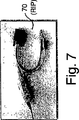
図13を参照すると、各ネットワークサーバ122は、ラックインターコネクトカード(RIC)インターフェイスカード90を含み、本明細書においては、図8において示されるようなRIC/ドーターカードを参照として援用する。各ネットワークサーバ122はまた、ネットワークサーバ122からのビデオ信号を受信し、そのビデオ信号を、ローカルエリアネットワーク(LAN)(好ましくは、イーサネット(R)LAN)を介して、リモートユーザに伝達するために、RIP70(図7)を含んでもよい。RIP内の回路の詳細は、本明細書中で、図14に関連して説明される。RIC90は、KVMビデオ信号をリモートユーザ112に送信するための送信回路(図18)を含む。例えば、巨視的に観ると、リモートユーザ112からネットワークサーバ122へ情報を伝達するためのシステムは、リモートユーザからの信号を受信するために、LAN110に接続するIPVモジュール114を含む。RCM116は、IPV114に接続し、ワイヤリングストリップ120は、RCM116と、それぞれのワイヤリングストリップ120に接続する複数のネットワークサーバとに接続する。IPV114、RCM116、および、ワイヤリングストリップ120は、リモートユーザ112およびネットワークサーバ122の中間の媒体として作用する。
Referring to FIG. 13, each
動作では、IPV114は、LAN110を介して、リモートユーザ112から、KM信号を受信し、アボセントロングラインインターコネクト(ALI)113を介して、RCM116から、KVM信号を受信する。IPV114によって受信されたALI、KVM信号は、RCMに設置されたプロセッサ(以下では「RCMプロセッサ」)(92)によって、RCMにおいて処理されたものである。リモートユーザ112は、複数のRCM入力ポート117に接続された複数のワイヤリングストリップ120を介して、複数のネットワークサーバ122の間で、特定のネットワークサーバを選択することができる。RCMプロセッサ92は、選択的に、ネットワークサーバ122から送信されるビデオ信号を処理し、ALIポート118、IPV114、および、LAN110を介してリモートユーザに信号を送信する。同様に、リモートユーザのKおよびMストロークは、LAN110を介してIPV114へ、次に、ALI118を介してRCM116プロセッサへ、送られる。RCMプロセッサ116は、続いて、ワイヤリングストリップ120へプラグ接続されたそれぞれのネットワークサーバへ信号を転送するために、信号を処理する。各ネットワークサーバ122に設置されたRIC90は、それぞれのネットワークサーバに対して、KおよびM信号をエミュレートする。RIC90は、さらに、コモンモード電圧の前後で、それぞれのネットワークサーバ122からのR、G、B信号を符号化することによって、ビデオ信号をスイッチする能力を有する。コモンモード電圧は、ネットワークサーバ122からのビデオ信号を選択するために、上がるか下がるかする。
In operation, the
別の実施形態では、ユーザ112とサーバ122との間の通信は、AVI114をバイパスし、LAN110およびRCM116を介して、実行される。しかし、本発明の動作は、AVI114を有する実施形態の動作に類似する。
In another embodiment, communication between
本発明の実施形態は、サーバ122へRICを組み込むか、または、上述のように、サーバ122のKVMコネクタに、外部的にRIPを接続することによって、等しく実施可能である。
Embodiments of the present invention are equally feasible by incorporating a RIC into the
ビデオオン、および、ビデオオフ信号を作動させるためのコモンモード信号方法は、HおよびV同期コーディング方法論の拡張である。図12に示されるシステムがどのように動作するかを示すために、以下に様々な回路図が説明される。RCMは、ワイヤリングストリップ120を介して選択された様々なサーバ(各々が図7〜9に示されるようなRIC/RIPを有する。)からの(KVM信号)を検知し、デジタル化するプロセッサ92を含む。RCM116に存在するスイッチは、AI入力117に接続された複数のRIC/RIPおよびPEM信号の間からのどのビデオ信号をデジタル化し、イーサネット(R)LAN110を介してリモートユーザ112に送るべきかを、選択する。同様に、リモートユーザのK、Mストロークは、イーサネット(R)LAN110を介して、RCMプロセッサ92へ送られる。RCMプロセッサ92は、ワイヤリングストリップ120にプラグ接続されたサーバ122へ、その信号を送信する。RCMプロセッサ92はまた、K、Mストロークを、ワイヤリングストリップ120を通過することなしに、直接サーバ122へ伝達させてもよい。RIC/RIP90、70は、それらがインターフェイスするそれぞれのサーバに対して、それぞれ、KおよびM信号をエミュレートする。RIC/RIP90、70は、さらに、どのサーバのビデオが、ワイヤリングストリップを介して、RCMへ送られるかをスイッチングするためのメカニズムを提供する。これは、ビデオにおけるコモンモード(CM)電圧を、上げるか下げるかすることによって達成される。ある特定のサーバが選択されない場合、その特定のサーバは、RCMへ順方向に結合すること(forward coupling)によって、そのビデオソースのビデオ情報部分を、オフにする。その結果、ワイヤリングストリップ(PEM)120に存在する寄生性の静電結合(parasitic capacitive coupling)が原因となって、干渉は誘発されず、それによって、ビデオノイズを排除される。
The common mode signaling method for activating the video on and video off signals is an extension of the H and V synchronous coding methodologies. Various circuit diagrams are described below to illustrate how the system shown in FIG. 12 operates. The RCM includes a
上述のように、ネットワークサーバRIPは、RCMシステムAI入力に、直接接続されてもよい。サーバ自体をRCM入力に接続する目的は、例えば、それぞれのサーバの重要性、接続されたサーバへのアクセスをブロックするかブロックしないかの必要性、および、ユーザによって決定されるような特定のサーバに対する所望のアクセサビリティの程度に基づく。 As described above, the network server RIP may be directly connected to the RCM system AI input. The purpose of connecting the server itself to the RCM input is, for example, the importance of each server, the need to block or not to access the connected server, and the specific server as determined by the user Based on the degree of accessibility desired.
ワイヤリングストリップは、短距離イントラ/インターラックシングル(short haul intra/inter rack single)カテゴリー5(CAT5)ケーブルKVM接続インターフェイスを定義する。このインターフェイスは、以下のように、4つのカテゴリー5(CAT5)ワイヤペアにおいて実装される。
Red Out +
Red Out −
Green Out +
Green Out −
Blue Out +
Blue Out −
Command +
Return
コマンドワイヤは、RCMとRIC/RIPとの間の半二重、マルチドロップ、非同期性のデータ接続である。この接続は、所与のRCM AIポートにおいて、アクティブなRIPまたはRICを制御し、RCMとアクティブなRIPとの間を、キーボード(K)およびマウス(M)情報を送って、利用される。さらに、この経路は、RIPソフトウェアのアップグレードをも支持する。
The wiring strip defines a short haul intra / inter rack single category 5 (CAT5) cable KVM connection interface. This interface is implemented in four Category 5 (CAT5) wire pairs as follows.
Red Out +
Red Out −
Green Out +
Green Out-
Blue Out +
Blue Out-
Command +
Return
The command wire is a half-duplex, multi-drop, asynchronous data connection between the RCM and RIC / RIP. This connection is utilized at a given RCM AI port, controlling the active RIP or RIC and sending keyboard (K) and mouse (M) information between the RCM and the active RIP. In addition, this path also supports RIP software upgrades.
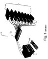
ここで、図6を参照すると、本発明の実施形態に応じた、ラックインターコネクトシステム/ワイヤリングストリップ120が示される。このシステム120は、仮想的に無制限な数の単一のラック内のコンピュータとの接続を提供するために、拡張されてもよい。このシステムは、さらに、アナログKVMに対して、単一のCAT5相互接続を提供する。ワイヤリングストリップ120は、8つのラックインターコネクション入力1201〜1208と、出力1209を含む。ワイヤリングストリップ120は、KVMスイッチ、サーバ、および、別のワイヤリングストリップとインターフェイスすることができる。
Referring now to FIG. 6, a rack interconnect system /
ここで、図10を参照すると、複数のインターコネクト入力117、ローカルアクセスのためのKVMポート115、ALIポート118、および、100base−Tイーサネット(R)LANポート119を有する、図12に示されるような、例示的なラックコネクションマネージャ(RCM)116が示される。ポート119は、サーバ122へのサーバコンソールアクセスか、もしくは、RCMへの管理およびメンテナンス情報の通信のためか、または、RCMおよびRIC/RIPソフトウェアをアップデートするために、リモートユーザ112によって利用され得る。上述したように、RCM116は、RCMプロセッサと、マトリクススイッチ/スイッチングサブシステム94とを含む。RCM116は、干渉なく、LAN110を介して、多重式同時式ユーザへのアクセスを提供する。ワイヤリングストリップ120(図6)およびネットワークサーバ122は、RICおよびRIP(図13)を介して、任意の組み合わせで、RCM116のARI入力117に接続され得る。ARI入力117の詳細は、図16に関連して説明される。図10Aは、図10で識別される、RCMの分解図を示す。
Referring now to FIG. 10, as shown in FIG. 12, having a plurality of
図11に関連して、例示的なアナログIPビデオ(IPV)モジュール114が示される。IPVモジュールは、ユーザ間の干渉なしに、多重式ユーザへのアクセスを提供する。IPVモジュールは、VGA、PS−2キーボード、および、マウス接続を含む1つのローカルKVM入力ポート111を含む。IPVモジュールは、ポート113を介して、多重式同時式デジタルKVMオーバーIP接続をも支持する。IPVモジュール114は、さらに、IPVモジュールへの全ての入力に対して、単一のLAN IP接続を提供し、例えば、ネットワークサーバ122の選択、サーバ122コンソール操作、および、IPV構成および管理機能のようなアクションを支持する。IPVモジュール114は、さらに、最長300メーターまでのUTPランに対するALI入力信号への歪み補正を提供する。
With reference to FIG. 11, an exemplary analog IP video (IPV)
ここで図13を参照すると、本発明の実施形態に従った、サーバ122の例示的な概略的なブロック図が示される。図12に示される各サーバ122は、マザーボードおよびRIC90を含む。他のコンポーネントは、簡単のために示されないが、サーバ122内に存在してもよい。サーバ122は、ラックインターコネクトPCIカードを有する標準のPCであり得る。ラックインターコネクトPCIカードは、サーバ122が、RCMおよびネットワーク110を介して、リモートユーザ112と通信するのを可能にする。ネットワーク110は、LANまたは他のネットワークであり得、イーサネット(R)、IP/TCPIP、または、他のデータプロトコルに、任意のプロトコルの制限なく準拠し得る。サーバ122は、RICにおいて実行され、マザーボード124においてキーボードおよびマウスポートに接続される、キーボードおよびマウスのエミュレーションから、キーボードおよびマウス命令を受信する。さらに、マザーボード124からのビデオ、キーボード、および、マウス信号は、RIC90を介して、RCM116へ送られる。
Referring now to FIG. 13, an exemplary schematic block diagram of the
図7〜9は、サーバコンソールインターフェイスへのアクセスを達成するための様々な代替の実施形態を示す。図7は、サーバへの外部接続を提供するためのラックインターフェイスポッド(RIP)を示す。図8は、サーバのマザーボードに直接備え付けられるように設計されたドーターカードを示す。ドーターカードは、サーバシステム内で利用可能なマザーボードメンテナンス信号の完全組み込みを提供する。図9は、サーバパワー制御へのアクセスおよび他のメンテナンス特性を提供することも可能なラックインターコネクトPCIカード実施形態を示す。 7-9 illustrate various alternative embodiments for achieving access to the server console interface. FIG. 7 shows a rack interface pod (RIP) for providing an external connection to a server. FIG. 8 shows a daughter card designed to be installed directly on the server motherboard. The daughter card provides full integration of motherboard maintenance signals available in the server system. FIG. 9 illustrates a rack interconnect PCI card embodiment that can also provide access to server power control and other maintenance characteristics.
図14は、RIP70内部に存在する、様々なサブシステムの概略図140を示す。概略図140は、全てRIP70内に設置された、それぞれのネットワークサーバ122からのビデオ(V)、キーボード(K)、および、マウス(M)信号を受信するための複数のインターフェイスポート、マイクロプロセッサ144、データリンクトランシーバサブシステム131、および、送信回路130を含む。プロセッサ144は、Vbias、Hsync、および、Vsync信号204、205、206を結合して、それぞれ、図20に示されるようなコモンモード信号を生成するために、スイッチング機能を制御する。
FIG. 14 shows a schematic diagram 140 of the various subsystems residing within the
図15を参照して、例示的なスイッチング回路150が示される。スイッチング回路150は、共通のディファレンシャルペアのスイッチされたワイヤバスへの各接続のために、ディファレンシャルペアあたり、複数のダイオード151、152を有する。スイッチング回路150は、ワイヤリングストリップ120の各ポート内に設置され、ワイヤリングストリップ120の詳細は、図12に関連して上述されたとおりである。受信するバスの終端で、コモンモードおよびディファレンシャルモードの終端処理の両方を提供することによって、個々のダイオード接続は、ネットワークサーバ122に関連したコモンモード電圧を変化させることにより、オン/オフされる。この形式では、ネットワークサーバ122からのビデオは、アクティブなスイッチングエレメントなしで、スイッチされる。むしろ、コモン電圧は、ネットワークサーバ122からのビデオ信号を選択するために、上がるか下がるかする。
Referring to FIG. 15, an
別の実施形態では、シングルエンドペアに対して、コンポジットシンクオングリーン符号化技術は、同期処理のために利用される。ここで、HおよびV信号は、コンポジットシンク信号へ結合される。コンポジットシンク信号は、さらに、グリーンビデオチャネルに結合される。この符号化技術は、複数のネットワークサーバの間で、あるネットワークサーバ122を選択するために利用される。簡単のために、シンクオングリーン符号化技術の詳細は、本明細書中で説明しない。
In another embodiment, for single-ended pairs, composite sync on green coding techniques are utilized for synchronization processing. Here, the H and V signals are combined into a composite sync signal. The composite sync signal is further coupled to the green video channel. This encoding technique is used to select a
ここで図16を参照して、RCM116(図12)内に設置される例示的な受信回路160が示される。受信回路は、明確にするために、単一のカラーコンポーネントチャネルを含むように示される。各R、G、Bチャネルが、各RCM116内のそのような各受信回路を含むことが理解される。図17は、HsyncおよびVsync信号用のデコーダを実装する回路の詳細を開示する。HsyncおよびVsync信号は、コモンモード信号に結合され、その結果、図18に示されるようなダイオードの多重化という目的のために、符号化されたコモンモード同期信号を有するディファレンシャル出力を生成する。差動的な受信器171、172は、R、G、Bビデオコンポーネントと、図15に示されるディファレンシャルスイッチングダイオードを制御するために利用されるDCコモンモード電流との両方を拒絶するHsyncおよびVsync信号を復号化するために利用される。
Referring now to FIG. 16, an
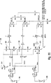
図18は、例示的なラックインターコネクト回路チャネルビデオ送信回路130の詳細を示す。概略図は、符号化されたコモンモード同期信号を有するディファレンシャル出力を示し、コモンモードは、ダイオードの多重化のための信号を有効にする。上述のように、ビデオ送信回路130は、各RIP70内に設置される。送信回路130は、イネーブルスイッチ132と、それぞれR、G、Bチャネルに対するディファレンシャルビデオドライバユニット133、134、135とを含む。各ビデオドライバユニットは、ディファレンシャルビデオドライビング回路を含む。各ディファレンシャルビデオドライバユニットは、例えば、スイッチされたR、G、B信号のようなシングルエンドビデオを受信し、その受信した信号を、各ビデオドライバユニット133、134、135の「+」および「−」出力で駆動されるように、ディファレンシャルビデオ信号へ変換する。R、G、Bペアは、R、G、Bビデオ信号と、HsyncおよびVsync信号に含まれるビデオ同期信号とのための差動的な経路を提供する。各R、G、B信号は、コモンモード電圧の前後に集中される。コモンモード電圧は、イネーブルスイッチ132から出る各R、G、Bチャネルと、拡張されたHsyncおよびVsync値とに対するイネーブル電圧の累積として、定義される。ビデオドライバ出力から提供される電圧は、以下のようになる。
有効
Green Out+=(Green+Vbias−Vssig)ボルト
Green Out−=(−Green+Vbias−Vssig)ボルト
Red Out+=(Red+Vbias+Vssig/2−Hssig)ボルト
Red Out−=(−Red+Vbias+Vssig/2−Hssig)ボルト
Red Out+=(Red+Vbias+Vssig/2+Hssig)ボルト
Red Out−=(−Red+Vbias+Vssig/2+Hssig)ボルト
ここで、Vssig=拡張された垂直同期信号の表示
Hssig=拡張された水平同期信号を表示
Vbias=一定のオフセット
無効
Green Out+=0ボルト
Green Out−=0ボルト
Red Out+=0ボルト
Red Out−=0ボルト
Red Out+=0ボルト
Red Out−=0ボルト
従って、例えば、スイッチされたR信号が、「x」ボルト増加した場合、ビデオドライバ133の「+」出力が、「x」ボルトに比例して増加し、「−」出力が、「x」ボルトに比例して減少する。このプロセスは、スイッチされたG、および、スイッチされたB入力に対して、同様に適用される。
FIG. 18 shows details of an exemplary rack interconnect circuit channel
Effectiveness
Green Out + = (Green + Vbias−Vssig) Volt Green Out − = (− Green + Vbias−Vssig) Volt Red Out + = (Red + Vbias + Vssig / 2−Hssig)
Where Vssig = display extended vertical sync signal Hssig = display extended horizontal sync signal Vbias = constant offset
Invalid
Green Out + = 0 volts Green Out− = 0 volts
Red Out + = 0 volts Red Out− = 0 volts
Red Out + = 0 volts Red Out− = 0 volts Thus, for example, if the switched R signal increases by “x” volts, the “+” output of the
従って、3つのR、G、Bディファレンシャル出力のいずれか1つのコモンモード電圧における任意の変化に対して、その他の出力の1つは、等しく、かつ、逆に変化する。これらの変化が発生する結果、カテゴリー5(CAT5)ケーブルにおけるドライバユニット133、134、135によって生成される交流の累積は、符号化された同期信号のために、ゼロになる。こうした要求は、信号ノイズおよび放射を防ぐ一方、信号のバランスを保つために、必要となる。さらに図18を参照すると、R、G、B信号は、ネットワークサーバ(図12)から、イネーブルスイッチ132において受信され、ビデオイネーブル信号は、プロセッサと、またRIP70内に含まれるスイッチング回路132とからも、受信される。R、G、B信号は、それぞれのビデオドライバ133、134、135のHsyncおよびVsync信号に、それぞれ結合される。最初の方で述べたように、R、G、B信号をHsyncおよびVsync信号と結合する回路は、RIP70内に含まれる各ビデオドライバユニットに存在する。
Thus, for any change in the common mode voltage of any one of the three R, G, B differential outputs, one of the other outputs will be equal and vice versa. As a result of these changes, the ac accumulation generated by the
ここで図19を参照すると、ダイオードでスイッチされたビデオ電流経路に対する例示的な回路図が示される。回路図は、2つの送信器を図示し、各送信器はRIP70(図7)からのチャネルを表わす。図19は、具体的に、別のRIP70に設置された2つの異なる送信器からのレッドチャネルの例示的なモデルを示す。ライティングストリップは、ディファレンシャルビデオ信号のためのダイオードスイッチングを提供し、接続されたRIC/RIPの間のコマンド接続に対する、スプリッタ/コンバイナ動作を実行する。この例示的な図では、VIDEO_INは、簡単のために、単一の入力として示される。しかし、R、G、および、B信号が、各送信器130に関連して表示される各VIDEO_INに対応することが、理解される。図20において示されるように生成されるコモンモード信号は、例示的なバッファおよび加算ノードを介して、VIDEO_IN信号に結合される。結合されたコモンモードおよびVIDEO_IN信号は、ソースエンドターミネーション195を通過し、ワイヤリングストリップのダイオード「d」を通過し、ワイヤリングストリップ120(図12)のポート1209で、一緒に加算される。ビデオ信号は、RCM116に設置された受信器(図16)において、受信される。
Referring now to FIG. 19, an exemplary circuit diagram for a diode switched video current path is shown. The circuit diagram illustrates two transmitters, each transmitter representing a channel from RIP 70 (FIG. 7). FIG. 19 specifically shows an exemplary model of a red channel from two different transmitters installed in another
動作においては、例えば、誰かが、送信器1におけるコモンモード(CM)電圧をON状態にし、同期(sync)信号をCM電圧信号上に置き、送信器2におけるCM電圧を「ゼロ」にし、そのビデオをOFFにした場合、送信器2は、OFFになり、送信器2に関連するワイヤリングストリップ120のダイオード「d」は、ワイヤリングストリップ120のバスから逆に偏向され、除去される。従って、ワイヤリングストリップ120を介したアクティブなビデオ信号のスイッチングは、インアクティブなチャネルに関連するダイオード「d」を逆に偏向する一方で、アクティブなチャネルに関連したダイオード「d」を介して電流を流すことによって、達成される。インアクティブなRIP70のアクティブなビデオドライブをオフにスイッチすることを伴うこのスイッチングメカニズムは、効果的に、ダイオードの容量が原因で、不要なビデオが「流れ出る」ことを妨げ、それによって、インアクティブなRIPケーブル配線からの伝送回線スタブ効果を排除する。
In operation, for example, someone turns on the common mode (CM) voltage at
図23は、ブレードサーバアーキテクチャで利用されるダイオードでスイッチされるビデオ電流経路の別の例示的な実施形態を示す。熟練者には、多重化サーバ(もしくは、「ブレード」)が共通のバックプレーンに接続された、公知のブレードサーバアーキテクチャおよびそれらの動作が、理解される。本発明は、例えば、図23に示されるようなブレードアーキテクチャにおいて、適用される。 FIG. 23 illustrates another exemplary embodiment of a diode switched video current path utilized in a blade server architecture. Those skilled in the art understand the known blade server architectures and their operation in which multiplexed servers (or “blades”) are connected to a common backplane. The present invention is applied, for example, in a blade architecture as shown in FIG.
図19および図23の比較から、ブレードアーキテクチャシステム(図23)の構造および動作は、ワイヤリングストリップの実施形態(図19)と一致することが、理解できる。実際、図19のシステムの動作についての上述の記述は、図23のシステムに関連して、等しく適用され、ここで再び援用される。ブレードアーキテクチャでは、送信器(図19)は、ワイヤリングストリップではなく、バックプレーン(図23)にプラグ接続されるカードと置き換えられる。そうでない場合は、動作は一致する。2枚のカードのみが、図23に示されるが、バックプレーンが物理的に適合する(封着を含む)のと同数のものが、描かれる。同様に、図23のアーキテクチャは、1つだけしか示されていないが、バックプレーン上の受信器の数について、制限はなされない。 From a comparison of FIGS. 19 and 23, it can be seen that the structure and operation of the blade architecture system (FIG. 23) is consistent with the wiring strip embodiment (FIG. 19). Indeed, the above description of the operation of the system of FIG. 19 applies equally to the system of FIG. 23, and is hereby incorporated again. In the blade architecture, the transmitter (FIG. 19) is replaced with a card that plugs into the backplane (FIG. 23) rather than a wiring strip. Otherwise, the behavior is consistent. Only two cards are shown in FIG. 23, but as many as the backplane is physically compatible (including sealing) are drawn. Similarly, although only one architecture is shown in FIG. 23, there is no limit on the number of receivers on the backplane.
図23に示されるように、ダイオードスイッチは、バックプレーン自体に設置される。RIPは、好ましくは、ブレード内に設置される。 As shown in FIG. 23, the diode switch is installed on the backplane itself. The RIP is preferably installed in the blade.
図23における参照番号190A〜195A、130A、120A、および、160Aは全て、それぞれ全体として機能と動作と残りのアーキテクチャの関係において、図19において、それらが対応する番号190〜195、130、120、および、160に対応する。
ここで図20を参照すると、HsyncおよびVsync信号をコモンモード信号と結合するための例示的な回路図が示される。回路200は、抵抗加算ノード201、202、203、および、Vbias(イネーブル電圧)を含む。HsyncおよびVsync信号は、それぞれのコモンモード電圧を生成するために、各R、G、B信号のためのイネーブル電圧と結合する。
Referring now to FIG. 20, an exemplary circuit diagram for coupling the H sync and V sync signals with the common mode signal is shown. The circuit 200 includes
一旦、ビデオ信号が、RCM116によって受信されると、それらのビデオ信号は、デジタル化され、そのビデオの変更は、ビデオのスクリーンとスクリーンとの変更をモニタリングし、リモートユーザ112によって、イーサネット(R)LAN110を介して、その変更をトラッキングすることによって、観測される。
Once the video signals are received by the
図21には、HsyncおよびVsync信号の関数として、コモンモードR、G、B信号の関連を示す例示的なプロットが描かれる。描かれた例示的なプロットからわかるように、CMグリーンのACコンポーネントは、Vsyncを反転したように示される。ACコンポーネントCMブルーは、1/2Vsync−Hsyncのように示される。ACコンポーネントCMレッドは、1/2Vsync+Hsyncのように示される。 FIG. 21 depicts an exemplary plot showing the association of common mode R, G, B signals as a function of the H sync and V sync signals. As can be seen from the illustrated example plot, the CM Green AC component is shown as having inverted V sync . AC component CM blue is shown as 1 / 2V sync -H sync . The AC component CM red is shown as 1 / 2V sync + H sync .
図22は、R、G、B、コモンモード(CM)信号を介して、送信器から受信器への交流の累積が、ゼロに等しいことを示す例示的なプロットを描く。プロットで示されたオーバーレイされたコモンモード同期信号は、図21に示されるようなコモンモード同期信号を表わす。コモンモードリターン電流は、R、G、および、Bドライバから受信器へ流れる全てのCM電流の累積である。従って、リターン信号以下のコモンモード同期電流およびイネーブル電流の累積は、ゼロに等しい。 FIG. 22 depicts an exemplary plot showing that the ac accumulation from the transmitter to the receiver is equal to zero via R, G, B, common mode (CM) signals. The overlaid common mode synchronization signal shown in the plot represents the common mode synchronization signal as shown in FIG. The common mode return current is the accumulation of all CM currents flowing from the R, G, and B drivers to the receiver. Therefore, the accumulation of common mode synchronization current and enable current below the return signal is equal to zero.
本発明のビデオをスイッチングする方法は、安価であり、さらに、サーバ管理を扱う際に、柔軟性を提供する。例えば、8x1多重化、または、N倍8x1多重化は、スイッチングエレメントを必要とするパワーソースなしで、可能となる。本発明のシステムは、低電力消費であり、サーバラックシステムに効果的に配置される。さらに、いくらかのライティングストリップは、ラック内に備え付けられ、続いて、ライティングストリップ出力は、管理上の目的のために、別のラックのRCMへルーティングされ得る。 The video switching method of the present invention is inexpensive and provides flexibility when dealing with server management. For example, 8 × 1 multiplexing or N × 8 × 1 multiplexing is possible without a power source that requires a switching element. The system of the present invention has low power consumption and is effectively placed in a server rack system. In addition, some lighting strips can be installed in the rack, and then the lighting strip output can be routed to another rack's RCM for administrative purposes.
現在のところ最も実用的であり、かつ、好ましい実施形態と考えられるものと関連して本発明が説明されたが、本発明は、開示された実施形態に限定されず、逆に、添付の特許請求の範囲の意図と範囲との中に含まれる様々な改良、および、同等の改変をもカバーすることが意図されていることが、理解されるべきである。 Although the present invention has been described in connection with what are presently considered to be the most practical and preferred embodiments, the present invention is not limited to the disclosed embodiments and, conversely, the appended patents. It should be understood that various modifications and equivalent modifications included within the spirit and scope of the claims are also intended to be covered.
Claims (10)
複数のコモンモード信号を該キーボード、ビデオ、マウス(KVM)信号管理システムに入力することであって、各コモンモード信号は、コモンモード電圧を有し、各コモンモード電圧は、該複数のビデオ信号のうちの1つに対応する、ことと、
該複数のビデオ信号を差動的に符号化することであって、該複数のビデオ信号は、それぞれのコモンモード電圧を中心とする電圧を有する、ことと、
該差動的に符号化された複数のビデオ信号を複数の対応するディファレンシャルビデオチャネルに入力することであって、各ディファレンシャルビデオチャネルは、対応するディファレンシャルワイヤペアを有する、ことと、
該複数のディファレンシャルビデオチャネルのそれぞれにダイオードのペアを組み込むことであって、該ダイオードのペアの一方のダイオードは、該対応するディファレンシャルワイヤペアの一方のワイヤに直列に接続されており、該ダイオードのペアの他方のダイオードは、該対応するディファレンシャルワイヤペアの他方のワイヤに直列に接続されており、該ダイオードのペアのそれぞれは、該複数のディファレンシャルビデオチャネルの間でスイッチングすることを目的として、該コモンモード電圧を増加または減少させることによって、順方向にバイアスされ、または、逆方向にバイアスされることにより、該複数のディファレンシャルビデオチャネルのそれぞれを有効または無効にする、ことと、
該複数のディファレンシャルビデオチャネルの中の選択ディファレンシャルビデオチャネルからビデオ信号を選択することと
を包含する、方法。A method of switching a plurality of video signals in a keyboard, video, mouse (KVM) signal management system, the method comprising:
Inputting a plurality of common mode signals to the keyboard, video, mouse (KVM) signal management system, wherein each common mode signal has a common mode voltage, and each common mode voltage is the plurality of video signals. Corresponding to one of the
The method comprising: differentially encoding the plurality of video signals, a video signal of said plurality of comprises a voltage centered on each of the common mode voltage, and that,
Inputting the differentially encoded video signals into a plurality of corresponding differential video channels , each differential video channel having a corresponding differential wire pair;
Incorporating a pair of diodes into each of the plurality of differential video channels, wherein one diode of the pair of diodes is connected in series with one wire of the corresponding differential wire pair; The other diode of the pair is connected in series to the other wire of the corresponding differential wire pair, and each of the pair of diodes is intended to switch between the plurality of differential video channels. Enabling or disabling each of the plurality of differential video channels by being forward biased or reverse biased by increasing or decreasing a common mode voltage;
Selecting a video signal from a selected differential video channel among the plurality of differential video channels.
(i)該差動的に符号化された複数のビデオ信号のそれぞれによって生成される交流は、実質的に正味ゼロであり、
(ii)該差動的に符号化された複数のビデオ信号に関連付けられた符号化された同期信号によって生成される交流は、実質的に正味ゼロである、ことと
をさらに包含する、請求項1に記載の方法。By driving the differentially encoded video signals differentially, each common mode voltage can be removed, and as a result,
(I) the alternating current produced by each of the plurality of differentially encoded video signals is substantially net zero;
(Ii) the alternating current generated by the encoded synchronization signal associated with the plurality of differentially encoded video signals is substantially net zero. The method according to 1.
各々のディファレンシャルビデオチャネルに対して前記スイッチングダイオードのペアを提供することであって、該ペアの一方のダイオードは、該ディファレンシャルビデオチャネルの半分に直列に接続されており、該ペアの他方のダイオードは、該ディファレンシャルビデオチャネルの残りの半分に直列に接続されている、ことと、
異なるビデオチャネルを共通のディファレンシャルチャネルに多重化することと、
各々のディファレンシャルチャネルに対するそれぞれのコモンモード信号の前後で、R、G、Bビデオ信号を符号化することと、
R、G、Bビデオ信号とそれぞれのコモンモード信号とを差動的に駆動することであって、該コモンモード信号は、ビデオ同期信号Hsync、Vsyncの関数をそれぞれ表す、ことと、
それぞれの個々のディファレンシャルチャネルのコモンモード電圧を変化させ、かつ、該スイッチングダイオードを順方向にバイアスするか、または、逆方向にバイアスすることにより、それぞれのディファレンシャルチャネルを有効、または、無効にすることによって、個々のディファレンシャルビデオチャネルをスイッチングすることと、
該ビデオ信号からコモンモード信号を除去し、元のビデオ同期信号を抽出するように、該R、G、Bビデオ信号を受信する終端において、コモンモードおよびディファレンシャルモードの終端処理の両方を提供することと
をさらに包含する、請求項1に記載の方法。Providing a plurality of interface ports for receiving RGB video signals from a plurality of servers, each of the plurality of interface ports including a differential video channel;
Providing a pair of switching diodes for each differential video channel, wherein one diode of the pair is connected in series with half of the differential video channel, and the other diode of the pair is Connected in series to the other half of the differential video channel;
Multiplexing different video channels onto a common differential channel;
Encoding R, G, B video signals before and after each common mode signal for each differential channel;
Differentially driving the R, G, B video signals and the respective common mode signals, the common mode signals representing functions of the video synchronization signals H sync , V sync , respectively;
Enabling or disabling each differential channel by changing the common mode voltage of each individual differential channel and biasing the switching diode forward or reverse To switch individual differential video channels,
Providing both common mode and differential mode termination at the termination receiving the R, G, B video signal so as to remove the common mode signal from the video signal and extract the original video synchronization signal further comprising the method of claim 1 and.
該拡張されたケーブル配線における該R、G、Bビデオ信号により被る伝送損失に対して訂正周波数補正を提供することと、
をさらに包含する、請求項1に記載の方法。Driving the R, G, B video signals in extended cabling;
Providing correction frequency correction for transmission losses incurred by the R, G, B video signals in the extended cabling;
The method of claim 1, further comprising:
該複数のサーバインターフェイスポートのそれぞれにおいて、前記複数のディファレンシャルビデオチャネルのそれぞれにスイッチングダイオードのペアを提供することと、
複数のディファレンシャルビデオチャネルを共通のディファレンシャルチャネルに多重化することと、
該複数のディファレンシャルチャネルのそれぞれに対するそれぞれのコモンモード信号の前後で、R、G、Bビデオ信号を符号化することと、
R、G、Bビデオ信号とそれぞれのコモンモード信号とを差動的に駆動することであって、該コモンモード信号は、ビデオ同期信号Hsync、Vsyncの関数をそれぞれ表す、ことと、
それぞれのチャネルのコモンモード電圧を変化させることによって、ディファレンシャルチャネルをスイッチングすることと、
受信する終端において、コモンモードおよびディファレンシャルモードの終端処理の両方を受信することと
をさらに包含する、請求項1に記載の方法。Providing a plurality of interface ports for receiving R, G, B video signals from a plurality of servers;
Providing a pair of switching diodes for each of the plurality of differential video channels at each of the plurality of server interface ports;
Multiplexing multiple differential video channels into a common differential channel;
Encoding R, G, B video signals before and after each common mode signal for each of the plurality of differential channels;
Differentially driving the R, G, B video signals and the respective common mode signals, the common mode signals representing functions of the video synchronization signals H sync , V sync , respectively;
Switching the differential channel by changing the common mode voltage of each channel;
The method of claim 1, further comprising: receiving both common mode and differential mode termination at a receiving end.
前記スイッチングダイオードを順方向にバイアスするか、または、逆方向にバイアスすることにより、それぞれ個々のディファレンシャルビデオチャネルを有効、または、無効にすることをさらに包含する、請求項6に記載の方法。The switching step includes:
7. The method of claim 6, further comprising enabling or disabling each individual differential video channel by biasing the switching diode in a forward direction or in a reverse direction .
元のビデオ同期信号を抽出することと
をさらに包含する、請求項7に記載の方法。Providing R, G, B video signals to remove common mode signals from the video signals;
The method of claim 7, further comprising extracting an original video synchronization signal.
該複数のサーバブレードバックプレーンスロットにおける該複数のサーバブレードが、共通に接続し、通信するバックプレーンであって、該複数のサーバブレードのそれぞれに対するダイオードのペアを含み、各々のダイオードのペアは、ディファレンシャルワイヤペアに直列に接続されており、該ダイオードのペアの一方のダイオードは、該ディファレンシャルワイヤペアの一方のワイヤに直列に接続されており、該ダイオードのペアの他方のダイオードは、該ディファレンシャルワイヤペアの他方のワイヤに直列に接続されており、該ダイオードのペアのそれぞれは、該差動的に符号化された複数のビデオ信号に対応する該複数のディファレンシャルワイヤペアの間でスイッチングを制御することを目的として、該コモンモード電圧を増加または減少させることによって、順方向バイアスされ、または、逆方向にバイアスされることにより、該複数のディファレンシャルワイヤペアのそれぞれを有効または無効にする、バックプレーンと、
該バックプレーンと通信する少なくとも1つの受信器であって、該ダイオードによってスイッチングされた該差動的に符号化された複数のビデオ信号を受信する少なくとも1つの受信器と
を備えた、ビデオ信号スイッチ。 A plurality of server blades backplane slots for receiving a plurality of server blades to output a plurality of common mode signal, each of the common mode signal of said plurality of common mode corresponding to one of a plurality of video signals A plurality of server blade backplane slots for outputting a plurality of differentially encoded video signals having a voltage centered on a respective common mode voltage. A plain slot,
The plurality of server blades in the plurality of server blade backplane slots are backplanes that are commonly connected and communicated, each including a pair of diodes for each of the plurality of server blades, each diode pair comprising: Connected in series to a differential wire pair, one diode of the pair of diodes is connected in series to one wire of the differential wire pair, and the other diode of the pair of diodes is connected to the differential wire Connected in series to the other wire of the pair, each of the pair of diodes controls switching between the plurality of differential wire pairs corresponding to the plurality of differentially encoded video signals. For this purpose, increase the common mode voltage. Or by decreasing, it is forward biased, or by being biased in the reverse direction, to enable or disable each of the plurality of differential wire pairs, and the backplane,
At least one receiver in communication with the backplane, the video signal switch comprising: at least one receiver for receiving the plurality of differentially encoded video signals switched by the diode .
Applications Claiming Priority (3)
| Application Number | Priority Date | Filing Date | Title |
|---|---|---|---|
| US27946101P | 2001-03-29 | 2001-03-29 | |
| US09/951,774 US7424551B2 (en) | 2001-03-29 | 2001-09-14 | Passive video multiplexing method and apparatus priority to prior provisional application |
| PCT/US2002/009595 WO2002080017A1 (en) | 2001-03-29 | 2002-03-29 | Passive video multiplexing method and apparatus |
Publications (3)
| Publication Number | Publication Date |
|---|---|
| JP2004536377A JP2004536377A (en) | 2004-12-02 |
| JP2004536377A5 JP2004536377A5 (en) | 2005-12-22 |
| JP4318922B2 true JP4318922B2 (en) | 2009-08-26 |
Family
ID=26959677
Family Applications (1)
| Application Number | Title | Priority Date | Filing Date |
|---|---|---|---|
| JP2002578172A Expired - Fee Related JP4318922B2 (en) | 2001-03-29 | 2002-03-29 | Passive video multiplexing method and apparatus |
Country Status (6)
| Country | Link |
|---|---|
| US (2) | US7424551B2 (en) |
| EP (1) | EP1388077A4 (en) |
| JP (1) | JP4318922B2 (en) |
| CA (2) | CA2768687A1 (en) |
| IL (2) | IL157619A0 (en) |
| WO (1) | WO2002080017A1 (en) |
Families Citing this family (54)
| Publication number | Priority date | Publication date | Assignee | Title |
|---|---|---|---|---|
| US6378014B1 (en) | 1999-08-25 | 2002-04-23 | Apex Inc. | Terminal emulator for interfacing between a communications port and a KVM switch |
| US20020054029A1 (en) * | 2000-11-28 | 2002-05-09 | Glancy John Thomas | Interactive display system |
| US7424551B2 (en) | 2001-03-29 | 2008-09-09 | Avocent Corporation | Passive video multiplexing method and apparatus priority to prior provisional application |
| US7398293B2 (en) * | 2002-04-17 | 2008-07-08 | Dell Products L.P. | System and method for using a shared bus for video communications |
| US7325033B2 (en) * | 2002-07-18 | 2008-01-29 | Clearcube Technology, Inc. | Video conferencing system using video manager to provide picture-in-picture image to display devices located remotely from co-located computing systems |
| US7684483B2 (en) * | 2002-08-29 | 2010-03-23 | Raritan Americas, Inc. | Method and apparatus for digitizing and compressing remote video signals |
| US7818480B2 (en) * | 2002-08-29 | 2010-10-19 | Raritan Americas, Inc. | Wireless management of remote devices |
| US8558795B2 (en) * | 2004-03-12 | 2013-10-15 | Riip, Inc. | Switchless KVM network with wireless technology |
| US7212961B2 (en) | 2002-08-30 | 2007-05-01 | Lsi Logic Corporation | Interface for rapid prototyping system |
| US7299427B2 (en) * | 2002-08-30 | 2007-11-20 | Lsi Corporation | Radio prototyping system |
| JP4601895B2 (en) * | 2002-09-26 | 2010-12-22 | 富士通コンポーネント株式会社 | Switching device and computer system |
| US7035955B2 (en) * | 2003-04-03 | 2006-04-25 | Dell Products L.P. | Blade server adapter card |
| EP1492010A1 (en) * | 2003-06-25 | 2004-12-29 | Agilent Technologies Inc | Remote management of a data processing unit allows power control from remote |
| US20050015430A1 (en) * | 2003-06-25 | 2005-01-20 | Rothman Michael A. | OS agnostic resource sharing across multiple computing platforms |
| US20050044266A1 (en) * | 2003-07-11 | 2005-02-24 | Digitalnet Government Solutions, Llc | High isolation KVM switch |
| US7454495B2 (en) * | 2003-09-18 | 2008-11-18 | Raritan America, Inc. | Intelligent modular server management system for selectively operating and locating a plurality of computers |
| JP4490077B2 (en) * | 2003-11-14 | 2010-06-23 | 富士通コンポーネント株式会社 | Server system, signal processing apparatus thereof, server thereof, and casing thereof |
| US8176155B2 (en) * | 2003-11-26 | 2012-05-08 | Riip, Inc. | Remote network management system |
| US7853663B2 (en) * | 2004-03-12 | 2010-12-14 | Riip, Inc. | Wireless management system for control of remote devices |
| TWI269992B (en) * | 2004-03-22 | 2007-01-01 | Aten Int Co Ltd | The keyboard video mouse switch for multiply chaining and the switching method of signals thereof |
| US20050216620A1 (en) * | 2004-03-26 | 2005-09-29 | Francisc Sandulescu | KVM and USB peripheral switch |
| US7415552B2 (en) * | 2004-04-15 | 2008-08-19 | Aten International Co., Ltd | Keyboard video mouse switch for multiple chaining and the method thereof |
| US7613854B2 (en) | 2004-04-15 | 2009-11-03 | Aten International Co., Ltd | Keyboard video mouse (KVM) switch wherein peripherals having source communication protocol are routed via KVM switch and converted to destination communication protocol |
| US20050273312A1 (en) * | 2004-06-03 | 2005-12-08 | Francisc Sandulescu | Distriubte USB KVM switch |
| US8069239B2 (en) * | 2004-07-20 | 2011-11-29 | Beckman Coulter, Inc. | Centralized monitor and control system for laboratory instruments |
| JP4693538B2 (en) * | 2004-08-25 | 2011-06-01 | 富士通コンポーネント株式会社 | Computer system |
| US8281031B2 (en) | 2005-01-28 | 2012-10-02 | Standard Microsystems Corporation | High speed ethernet MAC and PHY apparatus with a filter based ethernet packet router with priority queuing and single or multiple transport stream interfaces |
| TW200634545A (en) * | 2005-03-22 | 2006-10-01 | Wellsyn Technology Inc | Method of initializing a peripheral device for operating a computer system |
| US7586935B2 (en) * | 2005-03-25 | 2009-09-08 | Aten International Co., Ltd. | KVM switch with an integrated network hub |
| US7640382B2 (en) * | 2005-04-29 | 2009-12-29 | Avocent Corporation | Virtual media systems, methods and devices |
| US7202836B2 (en) * | 2005-05-06 | 2007-04-10 | Motorola, Inc. | Antenna apparatus and method of forming same |
| US8478884B2 (en) * | 2005-09-30 | 2013-07-02 | Riip, Inc. | Wireless remote device management utilizing mesh topology |
| US7752339B2 (en) * | 2005-10-11 | 2010-07-06 | Aten International Co., Ltd. | Matrix architecture for KVM extenders |
| US7689677B2 (en) * | 2006-02-17 | 2010-03-30 | Avocent Huntsville Corporation | Dynamic power cycling |
| US7852873B2 (en) * | 2006-03-01 | 2010-12-14 | Lantronix, Inc. | Universal computer management interface |
| TWM296418U (en) * | 2006-03-17 | 2006-08-21 | Alcor Micro Corp | Shared electronic peripheral equipment system |
| US8427489B2 (en) * | 2006-08-10 | 2013-04-23 | Avocent Huntsville Corporation | Rack interface pod with intelligent platform control |
| WO2008020897A2 (en) * | 2006-08-10 | 2008-02-21 | Avocent Huntsville Corporation | Rack interface pod with intelligent platform control |
| US8009173B2 (en) * | 2006-08-10 | 2011-08-30 | Avocent Huntsville Corporation | Rack interface pod with intelligent platform control |
| US20080040527A1 (en) | 2006-08-14 | 2008-02-14 | Filipov Metodi N | Management module |
| US8612548B2 (en) * | 2007-06-28 | 2013-12-17 | International Business Machines Corporation | Computer server system and computer server for a computer server system |
| JP5127366B2 (en) * | 2007-08-29 | 2013-01-23 | 富士通コンポーネント株式会社 | Information processing apparatus, KVM switch, server, and control program |
| CN101382846B (en) * | 2007-09-06 | 2011-08-31 | 宏正自动科技股份有限公司 | Mouse and control method thereof |
| US20090177901A1 (en) * | 2008-01-08 | 2009-07-09 | Aten International Co., Ltd. | Kvm management system capable of controlling computer power |
| JP4634499B2 (en) * | 2008-12-01 | 2011-02-16 | 富士通コンポーネント株式会社 | Image display method and image display program |
| US20110113166A1 (en) * | 2009-11-06 | 2011-05-12 | Cpo Technologies Corporation | Method and Apparatus of USB 3.0 Based Computer, Console and Peripheral Sharing |
| US20110113231A1 (en) * | 2009-11-12 | 2011-05-12 | Daniel Kaminsky | System and method for providing secure reception and viewing of transmitted data over a network |
| US8799633B2 (en) | 2011-02-11 | 2014-08-05 | Standard Microsystems Corporation | MAC filtering on ethernet PHY for wake-on-LAN |
| CN103139000A (en) * | 2011-11-28 | 2013-06-05 | 英业达科技有限公司 | Monitor method of multiple rack systems |
| KR102263369B1 (en) | 2015-01-13 | 2021-06-11 | 한국전자통신연구원 | System and method for multi-computer control |
| IL265789A (en) | 2019-04-01 | 2020-10-28 | Fibernet Ltd | Device for secure video streaming |
| IL266118B2 (en) | 2019-04-17 | 2023-08-01 | Fibernet Ltd | Device for secure unidirectional audio transmission |
| CN110121059B (en) * | 2019-05-08 | 2021-06-18 | 视联动力信息技术股份有限公司 | Monitoring video processing method, device and storage medium |
| CN114996186B (en) * | 2022-04-29 | 2024-02-06 | 深圳市倍思科技有限公司 | Docking station video output method, device, terminal and computer readable storage medium |
Family Cites Families (69)
| Publication number | Priority date | Publication date | Assignee | Title |
|---|---|---|---|---|
| US2667553A (en) | 1951-09-25 | 1954-01-26 | Metals & Controls Corp | Hermetically sealed thermostat |
| US2870287A (en) | 1956-02-13 | 1959-01-20 | Aerojet General Co | Electrical device |
| US4103252A (en) | 1976-11-26 | 1978-07-25 | Xerox Corporation | Capacitive touch-activated transducer system including a plurality of oscillators |
| US4395610A (en) | 1981-07-20 | 1983-07-26 | Technology Management, Inc. | Pivotable multipole switch |
| US5353409A (en) | 1987-09-11 | 1994-10-04 | Cybex Corporation | Computer-monitor extended range communications link |
| US4927787A (en) | 1989-02-09 | 1990-05-22 | Molex Incorporated | Unitarily molded electrical connector housing with separable key |
| US4919117A (en) | 1989-02-21 | 1990-04-24 | Thomas P. Muchisky | Facial and body massage apparatus and method |
| US4927987A (en) | 1989-02-24 | 1990-05-22 | Kirchgessner Steven J | Directional control device |
| US5033813A (en) | 1990-03-07 | 1991-07-23 | James L. Downey | Low loss fiber optic switch |
| US5272525A (en) | 1991-03-07 | 1993-12-21 | Recoton Corporation | System for local wireless transmission of signals at frequencies above 900 MHz |
| US5260532A (en) | 1991-11-01 | 1993-11-09 | United Technologies Automotive, Inc. | Sealed housing for a remote switching device |
| US5188542A (en) | 1991-12-05 | 1993-02-23 | Gray Ballman | Electrical connector with integral strain relief and mount, and overtemperature indicator |
| US5192226A (en) | 1992-05-06 | 1993-03-09 | Wang Tsan Chi | Double-output port cable assembly for notebook computers |
| US6150997A (en) | 1992-07-13 | 2000-11-21 | Cybex Computer Products Corporation | Video transmission system |
| US5926509A (en) | 1992-07-13 | 1999-07-20 | Cybex Computer Products Corporation | Twisted pair communicatons line system |
| US5573425A (en) | 1993-10-18 | 1996-11-12 | Asahi Kogaku Kogyo Kabushiki Kaisha | Communication cable used in a computer system |
| US5637013A (en) | 1994-12-16 | 1997-06-10 | Belden Wire & Cable Company | Power supply cord with a molded pre-assembled electrical contact carrier and the carrier |
| US5792986A (en) | 1995-01-05 | 1998-08-11 | Monster Cable International, Ltd. | Composite audio/video cable assembly |
| US5535036A (en) | 1995-01-18 | 1996-07-09 | Lighthouse Digital Systems, Inc. | Input/output module providing mixed optical and electrical signal connectivity in data communications equipment |
| EP0737908A1 (en) | 1995-04-12 | 1996-10-16 | Hewlett-Packard Company | Computer system having remotely operated interactive display |
| GB2302489A (en) | 1995-06-15 | 1997-01-15 | Ibm | Computer monitor with user-selectable communication protocol |
| US5721842A (en) | 1995-08-25 | 1998-02-24 | Apex Pc Solutions, Inc. | Interconnection system for viewing and controlling remotely connected computers with on-screen video overlay for controlling of the interconnection switch |
| JP3290063B2 (en) | 1996-01-30 | 2002-06-10 | 富士写真光機株式会社 | camera |
| US5742718A (en) | 1996-08-13 | 1998-04-21 | Eclipse Surgical Technologies, Inc. | Proprietary fiber connector and electronic security system |
| JPH1091300A (en) | 1996-09-12 | 1998-04-10 | Kokusai Electric Co Ltd | Connection controller for mouse |
| US5775939A (en) | 1996-10-08 | 1998-07-07 | Lucent Technologies Inc. | Interface assembly for peripheral accessories |
| US5913701A (en) | 1997-02-28 | 1999-06-22 | Adc Telecommunications, Inc. | DSX module with removable switching jack |
| US5744754A (en) | 1997-03-05 | 1998-04-28 | Hubbell Incorporated | Electrical receptacle incorporating integral electrical wire strain relief arrangement |
| US6557170B1 (en) * | 1997-05-05 | 2003-04-29 | Cybex Computer Products Corp. | Keyboard, mouse, video and power switching apparatus and method |
| JPH11168488A (en) | 1997-12-05 | 1999-06-22 | Sumitomo Wiring Syst Ltd | Hub switching device, wiring system using the same and method for using the same |
| US6304895B1 (en) | 1997-08-22 | 2001-10-16 | Apex Inc. | Method and system for intelligently controlling a remotely located computer |
| WO1999010801A1 (en) * | 1997-08-22 | 1999-03-04 | Apex Inc. | Remote computer control system |
| US5929386A (en) | 1997-09-11 | 1999-07-27 | Ryobi North America, Inc. | Power cord set for an electric tool |
| US20010044843A1 (en) | 1997-10-28 | 2001-11-22 | Philip Bates | Multi-user computer system |
| US6185643B1 (en) | 1997-11-15 | 2001-02-06 | Cybex Computer Products Corporation | Method and apparatus for extending the range between a computer and computer peripherals |
| US6038616A (en) * | 1997-12-15 | 2000-03-14 | Int Labs, Inc. | Computer system with remotely located interface where signals are encoded at the computer system, transferred through a 4-wire cable, and decoded at the interface |
| US6886055B2 (en) * | 1997-12-15 | 2005-04-26 | Clearcube Technology, Inc. | Computer on a card with a remote human interface |
| US6329616B1 (en) | 1998-02-10 | 2001-12-11 | Jae Ha Lee | Power control apparatus |
| US6119146A (en) * | 1998-05-04 | 2000-09-12 | Int Labs, Inc. | Computer network having multiple remotely located human interfaces sharing a common computing system |
| US6633934B1 (en) * | 1998-07-08 | 2003-10-14 | Clearcube Technology, Inc. | Computer system having reduced cabling requirements |
| US6192433B1 (en) | 1998-07-14 | 2001-02-20 | Tandem Computers Incorporated | Automatic SCSI termination readjustment |
| US6250936B1 (en) | 1998-08-05 | 2001-06-26 | Cisco Technology, Inc. | Single-port connection and circuitry accepting both balanced and unbalanced data signals |
| AU774003B2 (en) | 1998-09-22 | 2004-06-10 | Avocent Huntsville Corporation | System for accessing personal computers remotely |
| JP3669471B2 (en) | 1998-09-30 | 2005-07-06 | フジノン株式会社 | Video signal transmission device |
| US6137455A (en) * | 1998-10-26 | 2000-10-24 | Raritan Computer Taiwan, Inc. | Computer keyboard, mouse and VGA monitor signal transmission arrangement |
| US6618774B1 (en) * | 1999-03-17 | 2003-09-09 | Adder Technology Ltd. | Computer signal transmission system |
| US6671756B1 (en) * | 1999-05-06 | 2003-12-30 | Avocent Corporation | KVM switch having a uniprocessor that accomodate multiple users and multiple computers |
| US6256014B1 (en) | 1999-05-06 | 2001-07-03 | Avocent Corporation | Mouse ranking system for multiple users |
| IES990431A2 (en) * | 1999-05-26 | 2000-11-26 | Cybex Comp Products Internat L | High end KVM switching system |
| US6748005B1 (en) | 1999-08-02 | 2004-06-08 | Lucent Technologies Inc. | Methods and apparatus for providing a direct frequency hopping wireless interface with a personal computer |
| US6449866B1 (en) | 1999-08-04 | 2002-09-17 | The Stanley Works | Rule assembly with improved blade hook |
| US6378014B1 (en) | 1999-08-25 | 2002-04-23 | Apex Inc. | Terminal emulator for interfacing between a communications port and a KVM switch |
| US6601124B1 (en) | 2000-02-14 | 2003-07-29 | International Business Machines Corporation | Universal interface for selectively coupling to a computer port type and method therefor |
| JP2001283677A (en) | 2000-03-29 | 2001-10-12 | Tokai Rika Co Ltd | Switching device and its assembling method |
| US6609034B1 (en) | 2000-03-29 | 2003-08-19 | Epicenter, Incorporated | System and method for remotely controlling and monitoring a plurality of computer systems |
| US6350150B2 (en) | 2000-04-21 | 2002-02-26 | Deladurantaye, Iii Robert | Personal computer to home audio adapter |
| US6681250B1 (en) | 2000-05-03 | 2004-01-20 | Avocent Corporation | Network based KVM switching system |
| IT251799Y1 (en) | 2000-10-18 | 2004-01-20 | Meta System Spa | CONTINUITY GROUP WITH ORDER FOR ELECTRIC CABLES. |
| US6983340B1 (en) | 2001-02-09 | 2006-01-03 | Crystal Group Inc. | Method and system for extending a distance between a personal computer and a keyboard, video display, a mouse, and serial port |
| US7424551B2 (en) | 2001-03-29 | 2008-09-09 | Avocent Corporation | Passive video multiplexing method and apparatus priority to prior provisional application |
| US6498890B1 (en) | 2001-07-02 | 2002-12-24 | Lsi Logic Corporation | Connector cable for connecting between an optical cable and multiple devices |
| US6482042B1 (en) | 2001-08-29 | 2002-11-19 | Emc Corporation | Techniques for accessing a circuit board utilizing an improved adaptor |
| US20030123677A1 (en) | 2002-01-03 | 2003-07-03 | Tran Dong Hai | Stereonet device |
| US6623295B2 (en) | 2002-01-18 | 2003-09-23 | Deladurantaye, Iii Robert J. | Personal computer to home audio direct connecting adapter |
| GB0204035D0 (en) | 2002-02-21 | 2002-04-03 | Adder Tech Ltd | Interfacing devices |
| US7035112B2 (en) | 2002-07-08 | 2006-04-25 | Aten International Co., Ltd. | Automatic switch |
| US20040044822A1 (en) | 2002-09-03 | 2004-03-04 | Heng-Chien Chen | Computer I/O switching means based on network links |
| US7180908B2 (en) | 2002-09-19 | 2007-02-20 | Microsoft Corporation | Switch with tandem ports and outlet assembly |
| US6672896B1 (en) | 2003-01-15 | 2004-01-06 | Power Communication Tech. Co., Ltd. | Built-in KVM switch |
-
2001
- 2001-09-14 US US09/951,774 patent/US7424551B2/en not_active Expired - Fee Related
-
2002
- 2002-03-29 CA CA2768687A patent/CA2768687A1/en not_active Abandoned
- 2002-03-29 JP JP2002578172A patent/JP4318922B2/en not_active Expired - Fee Related
- 2002-03-29 CA CA2440246A patent/CA2440246C/en not_active Expired - Fee Related
- 2002-03-29 EP EP02757837A patent/EP1388077A4/en not_active Withdrawn
- 2002-03-29 IL IL15761902A patent/IL157619A0/en unknown
- 2002-03-29 WO PCT/US2002/009595 patent/WO2002080017A1/en active Application Filing
-
2003
- 2003-08-28 IL IL157619A patent/IL157619A/en unknown
-
2005
- 2005-05-06 US US11/123,075 patent/US7590763B2/en not_active Expired - Lifetime
Also Published As
| Publication number | Publication date |
|---|---|
| CA2440246A1 (en) | 2002-10-10 |
| WO2002080017A1 (en) | 2002-10-10 |
| CA2440246C (en) | 2012-05-01 |
| US7590763B2 (en) | 2009-09-15 |
| EP1388077A1 (en) | 2004-02-11 |
| US20050204082A1 (en) | 2005-09-15 |
| US7424551B2 (en) | 2008-09-09 |
| EP1388077A4 (en) | 2011-01-05 |
| IL157619A0 (en) | 2004-03-28 |
| JP2004536377A (en) | 2004-12-02 |
| CA2768687A1 (en) | 2002-10-10 |
| IL157619A (en) | 2010-11-30 |
| US20020143996A1 (en) | 2002-10-03 |
Similar Documents
| Publication | Publication Date | Title |
|---|---|---|
| JP4318922B2 (en) | Passive video multiplexing method and apparatus | |
| US6345323B1 (en) | Computer interconnection system | |
| CA2657977C (en) | High-end kvm switching system | |
| US6681250B1 (en) | Network based KVM switching system | |
| JP2004536377A5 (en) | ||
| US20050044186A1 (en) | Remote interface optical network | |
| US6678268B1 (en) | Multi-interface point-to-point switching system (MIPPSS) with rapid fault recovery capability | |
| US6426952B1 (en) | Multi-interface point-to-point switching system (MIPPSS) having an internal universal signal format | |
| US7249167B1 (en) | Intelligent modular server management system for selectively operating a plurality of computers | |
| US6580720B1 (en) | Latency verification system within a multi-interface point-to-point switching system (MIPPSS) | |
| US6628648B1 (en) | Multi-interface point-to-point switching system (MIPPSS) with hot swappable boards | |
| WO2002061594A1 (en) | High-end keyboard-video-mouse switching system | |
| AU702823C (en) | Computer interconnection system | |
| AU3392499A (en) | Computer interconnection system |
Legal Events
| Date | Code | Title | Description |
|---|---|---|---|
| A521 | Request for written amendment filed |
Free format text: JAPANESE INTERMEDIATE CODE: A523 Effective date: 20050329 |
|
| A621 | Written request for application examination |
Free format text: JAPANESE INTERMEDIATE CODE: A621 Effective date: 20050329 |
|
| A131 | Notification of reasons for refusal |
Free format text: JAPANESE INTERMEDIATE CODE: A131 Effective date: 20070425 |
|
| A601 | Written request for extension of time |
Free format text: JAPANESE INTERMEDIATE CODE: A601 Effective date: 20070718 |
|
| A602 | Written permission of extension of time |
Free format text: JAPANESE INTERMEDIATE CODE: A602 Effective date: 20070726 |
|
| A521 | Request for written amendment filed |
Free format text: JAPANESE INTERMEDIATE CODE: A523 Effective date: 20070827 |
|
| A131 | Notification of reasons for refusal |
Free format text: JAPANESE INTERMEDIATE CODE: A131 Effective date: 20080716 |
|
| A521 | Request for written amendment filed |
Free format text: JAPANESE INTERMEDIATE CODE: A523 Effective date: 20081016 |
|
| A131 | Notification of reasons for refusal |
Free format text: JAPANESE INTERMEDIATE CODE: A131 Effective date: 20090123 |
|
| A521 | Request for written amendment filed |
Free format text: JAPANESE INTERMEDIATE CODE: A523 Effective date: 20090422 |
|
| TRDD | Decision of grant or rejection written | ||
| A01 | Written decision to grant a patent or to grant a registration (utility model) |
Free format text: JAPANESE INTERMEDIATE CODE: A01 Effective date: 20090519 |
|
| A01 | Written decision to grant a patent or to grant a registration (utility model) |
Free format text: JAPANESE INTERMEDIATE CODE: A01 |
|
| A61 | First payment of annual fees (during grant procedure) |
Free format text: JAPANESE INTERMEDIATE CODE: A61 Effective date: 20090527 |
|
| FPAY | Renewal fee payment (event date is renewal date of database) |
Free format text: PAYMENT UNTIL: 20120605 Year of fee payment: 3 |
|
| R150 | Certificate of patent or registration of utility model |
Free format text: JAPANESE INTERMEDIATE CODE: R150 |
|
| LAPS | Cancellation because of no payment of annual fees |