JP4314101B2 - Filament winding device yarn feeding unit, filament winding device and structure manufacturing method - Google Patents
Filament winding device yarn feeding unit, filament winding device and structure manufacturing method Download PDFInfo
- Publication number
- JP4314101B2 JP4314101B2 JP2003391011A JP2003391011A JP4314101B2 JP 4314101 B2 JP4314101 B2 JP 4314101B2 JP 2003391011 A JP2003391011 A JP 2003391011A JP 2003391011 A JP2003391011 A JP 2003391011A JP 4314101 B2 JP4314101 B2 JP 4314101B2
- Authority
- JP
- Japan
- Prior art keywords
- fiber bundle
- winding
- guide
- resin
- filament winding
- Prior art date
- Legal status (The legal status is an assumption and is not a legal conclusion. Google has not performed a legal analysis and makes no representation as to the accuracy of the status listed.)
- Expired - Fee Related
Links
Images

Landscapes
- Forwarding And Storing Of Filamentary Material (AREA)
- Guides For Winding Or Rewinding, Or Guides For Filamentary Materials (AREA)
- Moulding By Coating Moulds (AREA)
- Yarns And Mechanical Finishing Of Yarns Or Ropes (AREA)
Description
本発明は、フィラメントワインディング装置の給糸ユニット及びフィラメントワインディング装置並びに構造体の製造方法関する。 The present invention relates to a yarn feeding unit of a filament winding apparatus, a filament winding apparatus, and a structure manufacturing method.
FRP(繊維強化プラスチック)製のパイプや容器(タンク)等の構造体を効率よく形成する方法としてフィラメントワインディング法がある。フィラメントワインディング法では一般に、マンドレルをその両端に突設された軸部で把持して所定の速度で回転させ、該マンドレルに対して樹脂を含浸させた繊維束を、マンドレルの軸方向に沿って往復移動する繊維束ガイド部材を介して巻き付ける。そして、フィラメントワインディング装置として、繊維束の巻付けに際して、マンドレルの回転角とガイド部材の移動量とをエンコーダで検出し、両者の動きをフィードバック制御することにより、軌跡及び巻付け量を精度良く制御できるようにした装置が知られている(例えば、特許文献1参照。)。 As a method for efficiently forming a structure such as a pipe or container (tank) made of FRP (fiber reinforced plastic), there is a filament winding method. Generally, in the filament winding method, a mandrel is gripped by shafts protruding at both ends thereof, rotated at a predetermined speed, and a fiber bundle impregnated with resin is reciprocated along the axial direction of the mandrel. It winds through the moving fiber bundle guide member. As a filament winding device, when winding a fiber bundle, the rotation angle of the mandrel and the amount of movement of the guide member are detected by an encoder, and the movement and movement of both are feedback-controlled to accurately control the trajectory and winding amount. An apparatus which can be used is known (for example, see Patent Document 1).
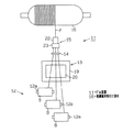
フィラメントワインディング装置において、円筒の両端に半球状のドーム部を備えた形状のタンクを生産する場合は、タンクと同様な形状のライナの表面に繊維束が巻き付けられる。繊維束の巻付けパターンとして、ヘリカル巻、パラレル巻及びレーベル巻がある。ヘリカル巻は、図6(a)に示すように繊維束Fがライナ50の軸線に対して斜めに巻き付けられ、パラレル巻は図6(b)に示すように繊維束Fがライナ50の軸線に対してほぼ90°に巻き付けられる。また、レーベル巻は図6(c)に示すように繊維束Fがライナ50の中心軸50aとほぼ平行に近くなるように、ライナ50にたすき掛けに巻き付けられる。
In a filament winding apparatus, when producing a tank having a hemispherical dome at both ends of a cylinder, a fiber bundle is wound around the surface of a liner having the same shape as the tank. As a winding pattern of the fiber bundle, there are a helical winding, a parallel winding, and a label winding. In the helical winding, the fiber bundle F is wound obliquely with respect to the axis of the
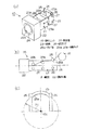
フィラメントワインディング装置に装備された繊維束ガイド部材は、一般に図7に示すように、ガイドパイプ51にベアリング52を介して回転可能に被回転伝達部53が支持されている。被回転伝達部53には、先端に繊維束案内部としてのフィードアイ54aを有するアーム54が、その基端において被回転伝達部53の端面に固定されている。アーム54の途中には繊維束Fを扁平にする作用を為すローラ55a,55bが設けられている。そして、図示しない繊維束供給部から供給される繊維束Fがガイドパイプ51を経て引き出され、フィードアイ54aを通って被繊維束巻付け部材へと扁平化された状態で送り出される。アーム54は、繊維束Fが被回転伝達部53の回転中心と一致する状態でフィードアイ54aと係合しつつ送り出される位置にフィードアイ54aを位置させるように、先端側が屈曲されている。
As shown in FIG. 7, the fiber bundle guide member provided in the filament winding apparatus generally has a rotation transmission portion 53 supported by a
そして、前記形状のライナに対する繊維束の巻き付けを円滑に行うには、フィードアイ54aは、ライナの胴部、即ち両端部より大径で径が一定な部分(円筒部)と対向する状態では基準位置に保持され、端部と対向する状態では基準位置から回動された位置に配置される必要がある。そのため、被回転伝達部53がモータ(図示せず)により回転されるようになっている。
In order to smoothly wind the fiber bundle around the liner having the above-mentioned shape, the
また、フィラメントワインディング装置の繊維束ガイド部材として、成形素材(樹脂含浸繊維束)の幅分を考慮した直径の異なるコロを糸出し本数に対応して配置したデリバリーアイが提案されている(特許文献2参照。)。そして、このデリバリーアイはフープ巻を行う場合と、ヘリカル巻を行う場合とで、コロの回転軸が90度異なるように回転させた位置に保持される。
従来の繊維束ガイド部材は、被繊維束巻付け部材に繊維束を巻き付ける際に、巻き付け角度によってフィードアイやデリバリーアイの向きを変更するために駆動源(モータ等)を必要とし、装置が大型化する。また、生産性向上のため複数本の繊維束を被繊維束巻付け部材に同時に巻き付ける場合には、繊維束ガイド部材を繊維束の本数に対応して設ける必要がある。しかし、フィードアイやデリバリーアイの向きを変更するために駆動源(モータ等)を必要とする構成では、可動部の重量増や制御の煩雑化を招き、高速化に不利となる。 The conventional fiber bundle guide member requires a drive source (motor, etc.) to change the direction of the feed eye and delivery eye depending on the winding angle when winding the fiber bundle around the fiber bundle winding member, and the apparatus is large. Turn into. Further, when simultaneously winding a plurality of fiber bundles around the fiber bundle winding member for improving productivity, it is necessary to provide fiber bundle guide members corresponding to the number of fiber bundles. However, in a configuration that requires a drive source (motor or the like) to change the direction of the feed eye or delivery eye, the weight of the movable part is increased and the control becomes complicated, which is disadvantageous for speeding up.
本発明は、前記従来の問題に鑑みてなされたものであって、その第1の目的は、出口ガイドを回転させる駆動源なしで、拡幅された繊維束を安定して被繊維束巻付け部材に巻き付けることができるフィラメントワインディング装置の給糸ユニットを提供することにある。また、第2の目的は、前記給糸ユニットを備えたフィラメントワインディング装置を提供することにある。また、第3の目的は、前記フィラメントワインディング装置を使用した繊維強化樹脂(FRP)製の構造体の製造方法を提供することにある。 The present invention has been made in view of the above-described conventional problems, and a first object thereof is to stably wind a widened fiber bundle without using a driving source for rotating an outlet guide. An object of the present invention is to provide a yarn feeding unit of a filament winding apparatus that can be wound around a wire. A second object is to provide a filament winding apparatus including the yarn feeding unit. A third object is to provide a method of manufacturing a structure made of fiber reinforced resin (FRP) using the filament winding apparatus.
前記第1の目的を達成するため、請求項1に記載の発明は、被繊維束巻付け部材を支持して回転させながら、繊維束を前記被繊維束巻付け部材の表面に巻き付けるフィラメントワインディング装置の給糸ユニットである。そして、前記被繊維束巻付け部材の回転に伴って引き出される繊維束に接触して繊維束をガイドする出口ガイドを支持する支持部が、フィラメントワインディング装置への取付け部に対して回転可能に支持されている。また、出口ガイドは支持部の回転中心軸側に凹となるように湾曲した形状のガイド面を有し、ガイド面の中央と対応する箇所が回転中心軸からの距離が最も遠い箇所となるように形成されるとともに、ガイド面の回転中心軸と直交する平面との交点の各点における曲率半径が、ガイド面の中央と対応する箇所における曲率半径以下に形成されている。
In order to achieve the first object, the invention according to
この発明では、出口ガイドを支持する支持部がフィラメントワインディング装置への取付け部に対して回転可能に支持され、出口ガイドは支持部の回転中心軸に対して偏心した箇所にガイド面が存在する。従って、被繊維束巻付け部材の回転に伴って引き出される繊維束から出口ガイドに対して前記回転中心軸を含む平面と交差する方向への力が作用するとその力によって支持部が回転され、モータ等の駆動手段を設ける必要がない。そして、ガイド面が支持部の回転中心軸側に凹となるように湾曲した形状のため、支持部が回転しても繊維束は回転中心軸からの距離が最も遠い箇所において安定した状態で引き出される。 In this invention, the support part which supports an exit guide is rotatably supported with respect to the attachment part to a filament winding apparatus, and a guide surface exists in the location where the exit guide is eccentric with respect to the rotation center axis | shaft of a support part. Accordingly, when a force in a direction intersecting the plane including the rotation center axis is applied to the exit guide from the fiber bundle drawn out as the fiber bundle winding member rotates, the support portion is rotated by the force, and the motor It is not necessary to provide a driving means such as. And since the guide surface is curved so as to be concave toward the rotation center axis side of the support part, the fiber bundle is pulled out in a stable state at the farthest distance from the rotation center axis even if the support part rotates. It is.
また、繊維束が支持部に回転力を付与する方向に引き出される際、繊維束は前記回転中心軸からの距離が最も遠い中央と対応する箇所に円滑に移動し、その箇所において安定して引き出される。 Further , when the fiber bundle is pulled out in the direction in which the rotational force is applied to the support portion, the fiber bundle smoothly moves to a position corresponding to the center farthest from the rotation center axis, and is stably pulled out at that position. It is.
請求項2に記載の発明は、請求項1に記載の発明において、前記出口ガイドは回転体形状に形成され、前記回転体の中心軸を回転中心として回転可能に設けられている。この発明では、出口ガイドが回転可能なため、出口ガイドが固定状態の場合に比較して繊維束が引き出される際に繊維束に加わる抵抗が小さくなる。 According to a second aspect of the present invention, in the first aspect of the present invention, the outlet guide is formed in a rotating body shape, and is provided rotatably about a central axis of the rotating body. In this invention, since the exit guide is rotatable, the resistance applied to the fiber bundle when the fiber bundle is pulled out is smaller than in the case where the exit guide is fixed.
請求項3に記載の発明は、請求項1又は請求項2に記載の発明において、前記出口ガイドは、前記ガイド面の前記回転中心軸と直交する平面との交線の曲率が一定に形成されている。従って、この発明では、出口ガイドは円弧状あるいは円環状に形成すればよく、出口ガイドを曲率が変化する放物線状や楕円状に形成する場合に比較して製作が容易になる。 According to a third aspect of the present invention, in the first or second aspect of the present invention, the exit guide has a constant curvature of intersection with the plane perpendicular to the rotation center axis of the guide surface. ing. Therefore, in the present invention, the exit guide may be formed in an arc shape or an annular shape, and the manufacture becomes easier as compared with the case where the exit guide is formed in a parabolic shape or an elliptical shape whose curvature changes.
請求項4に記載の発明は、請求項1〜請求項3のいずれか一項に記載の発明において、前記支持部には前記出口ガイドの繊維束引き出し方向上流側に、繊維束を拡げる作用を有する拡幅ガイドが設けられている。この発明では、拡幅ガイドで拡げられた繊維束が出口ガイドで案内されて幅が安定した状態で被繊維束巻付け部材に巻き付けられる。
The invention according to claim 4 is the invention according to any one of
請求項5に記載の発明は、請求項1〜請求項4のいずれか一項に記載の発明において、前記支持部及び該支持部に支持されている部材の全体の重心が前記支持部の回転中心に一致している。従って、この発明では、繊維束から支持部に回転力が付与される状態になると支持部が確実に回転され、繊維束に無理な力が加わらず出口ガイドにより繊維束が円滑に案内される。 According to a fifth aspect of the present invention, in the invention according to any one of the first to fourth aspects, the center of gravity of the support portion and a member supported by the support portion is the rotation of the support portion. It matches the center. Therefore, in this invention, when a rotational force is applied from the fiber bundle to the support portion, the support portion is reliably rotated, and the fiber bundle is smoothly guided by the exit guide without applying an excessive force to the fiber bundle.
請求項6に記載の発明は、請求項1〜請求項5のいずれか一項に記載の発明において、前記繊維束は、樹脂が含浸された繊維束である。この発明では、樹脂が含浸されていない状態の繊維束を被繊維束巻付け部材の表面に巻き付けた後、樹脂の含浸、硬化を行う場合に比較して、繊維束に必要量の樹脂を均一に含浸させるのが容易になる。
The invention according to claim 6 is the invention according to any one of
前記第2の目的を達成するため、請求項7に記載の発明のフィラメントワインディング装置は、請求項1〜請求項6のいずれか一項に記載の給糸ユニットを備えている。この発明では、請求項1〜請求項6のいずれか一項に記載の給糸ユニットを使用した場合と同様な作用効果を奏する。 In order to achieve the second object, a filament winding apparatus according to a seventh aspect of the present invention includes the yarn feeding unit according to any one of the first to sixth aspects. In this invention, there exists an effect similar to the case where the yarn feeding unit as described in any one of Claims 1-6 is used.
請求項8に記載の発明は、請求項7に記載の発明において、前記給糸ユニットは複数備えられている。この発明では、給糸ユニットが複数設けられているため、生産性が向上する。また、モータ等の駆動手段を設けることなく繊維束が引き出される力で支持部が回転されるため、給糸ユニットが複数設けられていてもフィラメントワインディング装置として給糸ユニットの配置スペースの確保が容易となる。
The invention according to claim 8 is the invention according to
第3の目的を達成するため、請求項9に記載の発明は、全体又は外郭が繊維強化樹脂により回転体形状に形成された構造体の製造方法である。そして、請求項7又は請求項8に記載のフィラメントワインディング装置を使用して被繊維束巻付け部材に樹脂が含浸された繊維束をヘリカル巻層及びレーベル巻層の少なくとも一方の巻層を含むように巻き付ける工程と、巻き付けられた繊維束に含浸された樹脂を硬化させる工程とを備えている。ここで、「被繊維束巻付け部材」とは、筒状の構造体を製造する際に使用するマンドレルや容器(タンク)を製造する際のライナ等、フィラメントワインディング装置のチャックに支持されて回転されてその外周に繊維束が巻き付けられるものを意味する。
In order to achieve the third object, the invention according to claim 9 is a method of manufacturing a structure in which the whole or the outer shell is formed into a rotating body shape with a fiber reinforced resin. The fiber bundle in which the fiber bundle winding member is impregnated with the resin using the filament winding apparatus according to
従って、この発明では、FRP製のパイプや容器(タンク)を製造する際、請求項7又は請求項8に記載のフィラメントワインディング装置を使用するため、繊維束の巻付けが円滑に行われ、品質が安定する。
Therefore, in the present invention, when the FRP pipe or container (tank) is manufactured, since the filament winding apparatus according to
請求項10に記載の発明は、全体又は外郭が繊維強化樹脂により回転体形状に形成された構造体の製造方法である。そして、請求項1〜請求項5に記載の給糸ユニットを少なくとも一個以上備えたフィラメントワインディング装置を使用して被繊維束巻付け部材に樹脂が含浸されていない繊維束をヘリカル巻層及びレーベル巻層の少なくとも一方の巻層を含むように巻き付ける工程と、巻き付けられた繊維束に樹脂を含浸させる工程と、巻き付けられた繊維束に含浸された樹脂を硬化させる工程とを備えている。この発明では、繊維束が巻き付けられた後、樹脂が繊維束に含浸される点が請求項9に記載の発明と異なるが、繊維束を巻き付ける際の作用、効果は同様である。
The invention according to claim 10 is a method of manufacturing a structure in which the whole or the outer shell is formed into a rotating body shape with a fiber reinforced resin. The fiber bundle in which the fiber bundle winding member is not impregnated with the resin using the filament winding apparatus provided with at least one yarn feeding unit according to
本発明によれば、給糸ユニットを回動させる駆動源なしで、拡幅された繊維束を安定して被繊維束巻付け部材に巻き付けることができる。 According to the present invention, the widened fiber bundle can be stably wound around the fiber bundle winding member without a drive source that rotates the yarn supplying unit.
(第1の実施形態)
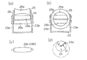
以下、本発明を具体化した第1の実施形態を図1〜図3に従って説明する。図1(a)は給糸ユニットの概略斜視図、(b)は給糸ユニットと被繊維束巻付け部材との位置関係を示す模式図、(c)は出口ガイドの作用を説明する模式図である。図2はフィラメントワインディング装置(以下、FW装置と称す。)の模式平面図、図3はFW装置の模式側面図である。
(First embodiment)
Hereinafter, a first embodiment of the present invention will be described with reference to FIGS. FIG. 1A is a schematic perspective view of a yarn supplying unit, FIG. 1B is a schematic diagram showing a positional relationship between the yarn supplying unit and the fiber bundle winding member, and FIG. 1C is a schematic diagram explaining the action of the outlet guide. It is. 2 is a schematic plan view of a filament winding apparatus (hereinafter referred to as FW apparatus), and FIG. 3 is a schematic side view of the FW apparatus.
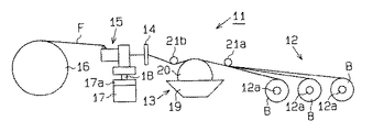
図2及び図3に示すように、FW装置11は、繊維束供給部12、樹脂含浸装置13、繊維束ガイド14及び給糸ユニット15を備えている。給糸ユニット15は、図示しないチャックに支持された被繊維束巻付け部材16の長手方向(図2における左右方向)に沿って往復移動可能に構成されている。給糸ユニット15を往復移動させる第1のアクチュエータ17には、ボールネジを使用するとともに、ナットと一体移動可能な移動体17aを1軸方向に移動させる構成の公知のものが使用されている。移動体17a上には、給糸ユニット15を昇降させる第2のアクチュエータ18が固定され、給糸ユニット15は第2のアクチュエータ18に取り付けられている。
As shown in FIGS. 2 and 3, the
繊維束供給部12は、繊維束Fが巻かれた複数(この実施形態では3つ)のボビンBが、張力調整装置(図示せず)に連結された支軸12aに支持される構成になっている。張力調整装置には例えばパウダーブレーキや、渦電流により支軸12aに負荷を加える構成の所謂パーマトルクが使用されている。繊維束Fは、例えば、炭素繊維の無撚りのマルチフィラメントからなり、マルチフィラメントはフィラメント数が3000〜96000本程度である。
The fiber
樹脂含浸装置13は、樹脂槽19及び塗布ローラ20を備え、樹脂槽19の上方にはボビンBから引き出された繊維束Fを樹脂槽19の所定位置に案内するローラ21aと、樹脂槽19で樹脂が含浸された後の繊維束Fを案内するローラ21bとが設けられている。なお、図2では、ローラ21a,21bの図示を省略している。また、繊維束供給部12とローラ21aとの間には、図示しないテンションローラが各繊維束Fに対応して設けられている。
The
繊維束ガイド14は複数のボビンBから引き出された繊維束Fがそれぞれ分離された状態で樹脂含浸作用を受けるように案内するため、櫛歯状のガイド部(図示せず)を備えている。
The
前記チャックは被繊維束巻付け部材16をその軸心を中心に回転可能に支持し、可変速モータにより回転駆動される。そして、制御装置(図示せず)により可変速モータが制御されて、チャックが給糸ユニット15の移動速度と同期した状態で回転駆動されることにより、繊維束Fの被繊維束巻付け部材16に対する巻付け角度を任意の角度に設定して巻き付けることができるようになっている。被繊維束巻付け部材16は、例えばマンドレルあるいはタンクを製造する場合のライナ等である。
The chuck supports the fiber
次に図1(a)〜(c)を参照しつつ、給糸ユニット15の構成について詳しく説明する。
給糸ユニット15は、FW装置11への取付け部22に対して支持部23が回転可能に支持されている。取付け部22は、直方体状のブロックの中心に断面円形の孔22aが形成され、孔22aに嵌合されるベアリング24を介して支持部23が回転可能に支持されている。支持部23は一対の支持壁23aを有し、支持壁23aには被繊維束巻付け部材16の回転に伴って引き出される繊維束Fに接触して繊維束Fをガイドする出口ガイド25が、取付け片26を介して支持されている。取付け片26にはねじ孔(図示せず)が形成され、取付け片26は支持壁23aに形成された長孔(図示せず)を貫通して前記ねじ孔に螺合されるねじ27により、支持壁23aに対して回転中心軸O1と直交する面内で位置調整可能に、即ち図1(a)における上下方向の位置調整可能に固定されている。
Next, the configuration of the
In the
出口ガイド25は支持部23の回転中心軸O1(図1(b),(c)に図示)側に凹となるように湾曲した形状のガイド面25aを有し、ガイド面25aの繊維束Fが通過可能な範囲内に、回転中心軸O1からの距離が最も遠い箇所が存在する。この実施形態では図1(c)に示すように、出口ガイド25は、ガイド面25aの前記回転中心軸O1と直交する平面との交線の各点における曲率半径が、ガイド面25aの前記回転中心軸O1からの距離が最も遠い箇所における曲率半径R1以下に形成されている。この実施形態では、出口ガイド25は断面円形のパイプ又はバーを円弧状に湾曲して形成され、ガイド面25aの前記回転中心軸O1と直交する平面との交線の各点における曲率が一定に形成されている。
The
支持部23には出口ガイド25の繊維束Fの引き出し方向上流側に、繊維束Fを拡げる(扁平にする)作用を有する拡幅ガイド28a,28bが設けられている。拡幅ガイド28a,28bの端面にはねじ孔(図示せず)が形成され、拡幅ガイド28a,28bも支持壁23aに形成された長孔(図示せず)を貫通して前記ねじ孔に螺合されるねじ27により、支持壁23aに対して図1(a)における上下方向の位置調整可能に固定されている。拡幅ガイド28a,28bは断面円形で直線状に形成されている。
The
支持部23には、支持部23及び支持部23に支持されている部材の全体の重心が支持部23の回転中心に一致させるためのバランスウエイト29(図1(b)にのみ図示)が固定されている。バランスウエイト29の端面にはねじ孔(図示せず)が形成され、バランスウエイト29も支持壁23aに形成された長孔(図示せず)を貫通して前記ねじ孔に螺合されるねじ27により、支持壁23aに対して図1(a)における上下方向の位置調整可能に固定されている。
A balance weight 29 (shown only in FIG. 1B) is fixed to the
次に前記のように構成された給糸ユニット15を備えたFW装置11の作用を説明する。
給糸ユニット15は取付け部22において第2のアクチュエータ18に固定されて、FW装置11に取り付けられる。そして、例えば、タンクを製造する場合は、先ず被繊維束巻付け部材16としてのライナをFW装置11のチャックに支持させる。次に第1のアクチュエータ17及び第2のアクチュエータ18を作動させて、給糸ユニット15を原位置(巻付け開始位置)に配置する。原位置は例えば、ライナの胴部の一端部と対応する位置に出口ガイド25が配置される位置である。
Next, the operation of the
The
次に繊維束供給部12から繰り出された繊維束Fを、樹脂含浸装置13及び繊維束ガイド14を経て給糸ユニット15に導き、図1(b)に示すように、拡幅ガイド28b,28a及び出口ガイド25と係合する状態で、繊維束Fの端部を被繊維束巻付け部材16の所定位置に固定する。繊維束Fの端部の固定作業は作業者が手作業で行い、例えば粘着テープを使用して行われる。また、被繊維束巻付け部材16の長さ、径、被繊維束巻付け部材16の回転速度、繊維束Fの被繊維束巻付け部材16への巻付け時の幅等の巻付け条件を制御手段に入力する。
Next, the fiber bundle F fed out from the fiber
次にFW装置11による繊維束Fの巻付け運転が開始される。FW装置11の運転が開始されると、被繊維束巻付け部材16が一定方向に回転されるとともに、第1のアクチュエータ17の駆動により、給糸ユニット15が移動体17aと共に巻付け開始位置から被繊維束巻付け部材16の軸方向と平行に移動される。そして、繊維束供給部12から繊維束Fが順次引き出されて被繊維束巻付け部材16上に巻き付けられる。
Next, the winding operation of the fiber bundle F by the
繊維束Fが被繊維束巻付け部材16に巻き付けられる際、出口ガイド25には繊維束Fから力が作用する。繊維束Fから作用する力の方向は、被繊維束巻付け部材16に対する繊維束Fの巻き付け角度に対応する。フープ巻の場合は、繊維束Fはほぼ回転中心軸O1を含む垂直面内において引き出されるため、繊維束Fからは支持部23を回転させる力が付与されず、繊維束Fは出口ガイド25のガイド面25aの中央部分でガイドされながら引き出される。
When the fiber bundle F is wound around the fiber
一方、ヘリカル巻やレーベル巻の場合は、繊維束Fは回転中心軸O1を含む垂直面と交差する方向に引き出される状態となる。この状態では繊維束Fからは支持部23に対して、出口ガイド25を介して支持部23を回転させる力が付与され、その力によって支持部23が回転される。繊維束Fはガイド面25aのうち、回転中心軸O1からの距離が最も遠い箇所において安定した状態で引き出される。
On the other hand, in the case of helical winding or label winding, the fiber bundle F is pulled out in a direction intersecting the vertical plane including the rotation center axis O1. In this state, a force for rotating the
出口ガイド25が直線状に形成されている場合、あるいは回転中心軸O1側に凸となる形状に形成されている場合は、回転中心軸O1からの距離が最も遠い箇所は、出口ガイド25の端部となり、繊維束Fが出口ガイド25の端部まで移動してその位置で引き出される。従って、拡幅ガイド28a,28bの作用によって扁平に拡げられた繊維束Fが再び収束された状態で引き出されるようになり、繊維束Fを扁平な状態で被繊維束巻付け部材16に安定して巻き付けるのが難しくなる。
When the
しかし、この実施形態では、ガイド面25aは出口ガイド25の中央が回転中心軸O1からの距離が最も遠い箇所のため、繊維束Fはガイド面25aの中央と対応する箇所において安定した状態で引き出される。従って、拡幅ガイド28a,28bの作用によって扁平に拡げられた繊維束は、扁平な状態で被繊維束巻付け部材16に安定して巻き付けられる。
However, in this embodiment, since the
移動体17aの移動速度及び被繊維束巻付け部材16の回転速度の調整により、ヘリカル巻層、フープ巻層及びレーベル巻層の巻付けが行われ、ヘリカル巻層、フープ巻層及びレーベル巻層が所定層数巻き付けられた時点で繊維束Fの巻付けが完了する。そして、被繊維束巻付け部材16に巻き付けられた繊維束Fの端部が被繊維束巻付け部材16に固定され、固定部から出口ガイド25に連なる繊維束Fが切断される。次に被繊維束巻付け部材16がチャックから取り外されて加熱炉に入れられ、所定温度で樹脂が硬化されて、外郭が繊維強化樹脂により回転体形状に形成された構造体としての回転対称形状のタンクが形成される。
The helical winding layer, the hoop winding layer, and the label winding layer are wound by adjusting the moving speed of the moving
この実施の形態では以下の効果を有する。
(1) 給糸ユニット15は、被繊維束巻付け部材16の回転に伴って引き出される繊維束Fに接触して繊維束Fをガイドする出口ガイド25を支持する支持部23が、FW装置11への取付け部22に対して回転可能に支持されている。従って、被繊維束巻付け部材16の回転に伴って引き出される繊維束Fから出口ガイド25に対して回転中心軸O1を含む平面と交差する方向への力が作用するとその力によって支持部23が回転され、モータ等の駆動手段を設けずに、支持部23が繊維束Fの引き出しが円滑に行われる方向に回転される。また、出口ガイド25は支持部23の回転中心軸O1側に凹となるように湾曲した形状のガイド面25aを有し、ガイド面25aの繊維束Fが通過可能な範囲内に回転中心軸O1からの距離が最も遠い箇所が存在する。従って、支持部23が回転しても繊維束Fは回転中心軸からの距離が最も遠い箇所において安定した状態で引き出される。その結果、出口ガイド25を回転させる駆動源なしで、拡幅された繊維束Fを安定して被繊維束巻付け部材16に巻き付けることができる。また、駆動源がないため、部品点数が少なくなり、構造が簡単で軽量化を図ることができる。
This embodiment has the following effects.
(1) In the
(2) ガイド面25aの回転中心軸O1と直交する平面との交線の各点における曲率半径が、ガイド面25aの回転中心軸O1からの距離が最も遠い箇所における曲率半径以下に形成されている。従って、繊維束Fが支持部23に回転力を付与する方向に引き出される際、繊維束Fは回転中心軸O1からの距離が最も遠い箇所に円滑に移動し、その箇所において安定して引き出される。
(2) The radius of curvature at each point of the line of intersection with the plane orthogonal to the rotation center axis O1 of the
(3) 出口ガイド25は、ガイド面25aの回転中心軸O1と直交する平面との交線の各点における曲率が一定(この実施形態では円弧状)に形成されている。従って、出口ガイド25を曲率が変化する放物線状や楕円状に形成する場合に比較して、出口ガイド25の製作が容易になる。
(3) The
(4) 支持部23には出口ガイド25の繊維束引き出し方向上流側に、繊維束Fを拡げる作用を有する拡幅ガイド28a,28bが設けられている。従って、拡幅ガイドが給糸ユニット15より上流側に配置され、拡幅ガイドから出口ガイド25までの距離が長い場合に比較して、繊維束Fが出口ガイド25で案内されて幅が安定した状態で被繊維束巻付け部材16に巻き付けることができる。また、わざわざ拡幅ガイドを支持する支持部材を別に設ける必要がなく、拡幅ガイドの配設が容易になる。
(4) The
(5) 支持部23及び支持部23に支持されている部材、即ち出口ガイド25、拡幅ガイド28a,28b及びバランスウエイト29等の全体の重心が、支持部23の回転中心に一致している。従って、繊維束Fから支持部23に回転力が付与される状態になると支持部23が確実に回転され、繊維束Fに無理な力が加わらず出口ガイド25により繊維束Fが円滑に案内される状態に、自動的に回転される。
(5) The entire center of gravity of the
(6) FW装置11は樹脂含浸装置13を備え、樹脂含浸装置13において樹脂が含浸された繊維束Fが給糸ユニット15に供給される。従って、給糸ユニット15に装備された出口ガイド25及び拡幅ガイド28a,28bとして、回転可能なローラを使用しなくても、繊維束Fが出口ガイド25及び拡幅ガイド28a,28bと接触しながら移動する際の抵抗が小さくなる。その結果、出口ガイド25及び拡幅ガイド28a,28bをローラ構成とする場合に比較して、構成が簡単になる。
(6) The
(7) 出口ガイド25及び拡幅ガイド28a,28bが支持部23に対して、回転中心軸O1と直交する面内で位置調整可能に固定されている。従って、位置調整不能に固定される構成に比較して、フィラメントワインディングの条件(例えば、被繊維束巻付け部材16の径、繊維束Fの太さ、繊維束Fの材質等)が変更された場合に、より適正な位置に調整することが可能となる。
(7) The
(8) バランスウエイト29が支持部23に対して、回転中心軸O1と直交する面内で位置調整可能に固定されている。従って、出口ガイド25及び拡幅ガイド28a,28bの位置調整を行った際に、支持部23及び支持部23に支持された部材全体の重心を23の回転中心に一致させることができる。
(8) The
(9) FW装置11は、複数本の繊維束Fを繊維束供給部12から同時に引き出し、出口ガイド25から被繊維束巻付け部材16に供給する際に、各繊維束Fを幅方向の端部で重ね合わせた状態で送り出す構成となっている。従って、複数本の繊維束Fの合計本数と同じ本数のフィラメントを有する太い繊維束Fを1本使用して巻付けを行う場合に比較して、繊維束Fの拡幅処理や樹脂含浸処理が容易になる。また、ガイド面25aが支持部23の回転中心軸O1側に凹となるように湾曲した形状のため、複数本の繊維束Fを同時に供給し、それぞれ拡幅された状態で出口ガイド25に導かれた繊維束Fをその幅方向の端部が重なった状態で被繊維束巻付け部材16へ安定して案内することができる。
(9) When the
(第2の実施形態)
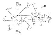
次に第2の実施形態を図4に従って説明する。この実施形態ではFW装置11が、給糸ユニット15を複数備え、被繊維束巻付け部材16に扁平な状態の繊維束Fが複数本同時に巻き付けられるように構成されている点が前記第1の実施形態と大きく異なっている。前記第1の実施形態と同一部分は同一符号を付して詳しい説明を省略する。
(Second Embodiment)
Next, a second embodiment will be described with reference to FIG. In this embodiment, the
FW装置11は、給糸ユニット15を8個備え、各給糸ユニット15が被繊維束巻付け部材16を中心としてその周囲にほぼ等間隔で配設されている。各給糸ユニット15に対応して繊維束供給部12及び繊維束ガイド14がそれぞれ同数設けられている。樹脂含浸装置13は繊維束供給部12の数より少なく設けられ、例えば、1台の樹脂含浸装置13が2個の繊維束供給部12で共用されるようになっている。そして、樹脂含浸装置13で樹脂が含浸されたガイド30を介して給糸ユニット15へ案内される。なお、図4においては、繊維束供給部12、樹脂含浸装置13、繊維束ガイド14、第1のアクチュエータ17、第2のアクチュエータ18の大部分の図示を省略している。
The
この実施形態のFW装置11では、フィラメントワインディングの準備作業において、各繊維束供給部12から前記第1の実施形態と同様に繊維束Fが引き出され、樹脂含浸装置13及び繊維束ガイド14等を経て給糸ユニット15に導かれ、被繊維束巻付け部材16に各繊維束Fの端部が周方向に等間隔をおいて固定される。そして、フープ巻を行う場合は、各出口ガイド25から引き出される繊維束Fが重ならないように被繊維束巻付け部材16の軸方向にずれた位置関係となるように給糸ユニット15の位置が調整された状態で、繊維束Fの巻付けが行われる。また、フープ巻及びレーベル巻を行う場合は、各出口ガイド25から引き出される繊維束Fの位置が軸方向において一致する位置関係となるように給糸ユニット15の位置が調整された状態で、繊維束Fの巻付けが行われる。
In the
この実施形態では、第1の実施形態の(1)〜(9)と同様な効果を有する他に、次の効果を有する。
(10) 給糸ユニット15が複数設けられているため、給糸ユニット15が1個の場合に比較して、生産性を複数倍に上げることが可能になる。
This embodiment has the following effects in addition to the same effects as (1) to (9) of the first embodiment.
(10) Since a plurality of
(11) 給糸ユニット15を被繊維束巻付け部材16に沿って移動させる第1のアクチュエータ17として、ボールネジを使用するとともに、ナットと一体移動可能な移動体17aを1軸方向に移動させる構成のものが使用されている。従って、複数の給糸ユニット15の軸方向の位置調整を簡単に、かつ精度良く行うことができる。
(11) A configuration in which a ball screw is used as the
なお、実施形態は前記に限定されるものではなく、例えば、次のように具体化してもよい。
○ 出口ガイド25は支持部23の回転中心軸側に凹となるように湾曲した形状のガイド面25aを有し、ガイド面25aの繊維束Fが通過可能な範囲内に回転中心軸O1からの距離が最も遠い箇所が存在する構成は、前記実施形態のように、円弧状に形成されるとともに、中央が回転中心軸O1からの距離が最も遠い箇所となる構成に限らない。例えば、回転中心軸O1からの距離が最も遠い箇所が中央ではなく、中央からいずれか一方にずれた箇所としてもよい。従って、出口ガイド25が円弧状であれば、図1(a)における支持壁23aの下端から出口ガイド25の両端までの高さが異なる状態に配置され、支持壁23aの下端から出口ガイド25の両端までの高さが同じ場合は、出口ガイド25は円弧ではない湾曲形状となる。
In addition, embodiment is not limited to the above, For example, you may actualize as follows.
The
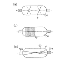
○ 出口ガイド25は支持部23に対して回転不能な構成に限らず、ガイド面25aが繊維束Fの引き出しに対応して回転可能な構成としてもよい。例えば、出口ガイド25が回転体形状に形成され、回転体の中心軸を回転中心として回転可能に設けられていてもよい。図5(a)は、鼓形状に形成され、取付け片26に回転可能に支持された出口ガイド25を示す。出口ガイド25が回転可能に構成された場合、繊維束Fが引き出される際の抵抗が小さくなる。従って、フィラメントワインディングに使用される繊維束Fとして、予め必要量の樹脂が付着(含浸)された半硬化状態の繊維束(所謂トウプリプレグ)を使用する場合でも、繊維束Fに無理な力がかかることが防止され、繊維束Fが円滑に引き出される。
The
○ ガイド面25aを円弧状とした出口ガイド25として、例えば図5(b)に示すように、円環状の出口ガイド25を使用してもよい。この構成では、出口ガイド25の一部のみ(図5(b)における出口ガイド25の上側部分)がガイド面25aとして使用され、他の部分はガイド面25aとして使用されない。この場合、出口ガイド25を支持部23に取り付けるのに取付け片26が不要となり、部品点数が少なくなる。
As the
○ 出口ガイド25の中央が回転中心軸O1からの距離が最も遠い箇所となる構成として、出口ガイド25の形状は円弧状に限らず、例えば楕円弧状や放物線状で対称な形状としてもよい。即ち、出口ガイド25は、ガイド面25aの回転中心軸O1と直交する平面との交線の曲率が一定に形成されている必要はない。しかし、出口ガイド25を円弧状あるいは円環状に形成する方が、出口ガイド25を前記曲率が変化する放物線状や楕円状に形成する場合に比較して製作が容易になる。
As a configuration in which the center of the
○ 拡幅ガイド28a,28bは径が一定に限らず、例えば、図5(c)に示すように中央部の径が最大で両端部の径が最小となる回転体形状としてもよい。この場合、径が一定の場合に比較して、拡幅作用が向上する。 ○ The widening guides 28a and 28b are not limited to a constant diameter, and may be, for example, a rotating body having a maximum diameter at the center and a minimum diameter at both ends as shown in FIG. In this case, the widening effect is improved as compared with the case where the diameter is constant.
○ 拡幅ガイドの数は2個に限らず、1個あるいは3個以上でもよい。また、拡幅ガイドを給糸ユニット15に設けず、給糸ユニット15より繊維束Fの引き出し方向上流側に設けたり、拡幅ガイドを省略したりしてもよい。拡幅ガイドを省略しても繊維束Fが出口ガイド25を通過する際に繊維束Fが扱かれて多少扁平化される。
○ The number of widening guides is not limited to two, but may be one or three or more. Further, the widening guide may not be provided in the
○ 拡幅ガイドは断面円形に限らず、繊維束Fとの接触部が湾曲面で構成されていればよく、例えば、断面円弧状の板材を凸部側が繊維束Fと対向するように配設してもよい。
○ 出口ガイド25は支持部23の回転中心軸側に凹となるように湾曲した形状のガイド面25aを有し、ガイド面25aの繊維束Fが通過可能な範囲内に前記回転中心軸からの距離が最も遠い箇所が存在する構成にかぎらず、出口ガイドは支持部23の回転中心軸O1に対して偏心した位置にガイド面が存在する構成であればよい。例えば、図5(d)に示すように、先端にガイド面を構成するリング状のガイド部31aを有する出口ガイド31の基端を、支持部23の回転中心軸O1に対して偏心した位置に支持軸32を介して回動可能に設けてもよい。この構成では、ヘリカル巻やレーベル巻の場合、繊維束Fが回転中心軸O1を含む垂直面と交差する方向に引き出される状態になると、先ず出口ガイド31が支持軸32を中心に回動されて例えば図5(d)に示す状態となる。この状態では支持軸32から支持部23に対して、支持部23を回転させる力が付与され、その力によって支持部23が、ガイド部31a、支持軸32及び回転中心軸O1が一直線上に位置する状態となるまで回転される。そして、繊維束Fはガイド面が回転中心軸O1からの距離が最も遠い箇所において安定した状態で引き出される。
○ The widening guide is not limited to a circular cross section, and the contact portion with the fiber bundle F may be formed of a curved surface. For example, a plate having an arc cross section is disposed so that the convex side faces the fiber bundle F. May be.
The
○ 支持部23及び支持部23に支持されている部材の全体の重心が支持部23の回転中心に一致している構成として、支持部23と別体のバランスウエイト29を設ける代わりに、支持部23の厚さを部分的に変えて前記全体の重心が支持部23の回転中心に一致するように構成してもよい。
○ Instead of providing a
○ 支持部23及び支持部23に支持されている部材の全体の重心が支持部23の回転中心に一致していなくてもよい。前記全体の重心が支持部23の回転中心に一致していなくても、繊維束Fの張力により出口ガイド25が繊維束Fの巻付けに適した状態となるように支持部23が回転される。しかし、繊維束Fに掛かる負荷を少なくするためには、前記全体の重心が支持部23の回転中心に一致している方が良い。
(Circle) the center of gravity of the
○ FW装置11は、繊維束供給部12として、ボビンBに予め必要量の樹脂が付着(含浸)された未硬化状態の繊維束(所謂トウプリプレグ)が巻かれたものを使用してもよい。この場合、樹脂含浸装置13が不要になり、給糸ユニット15を複数設けたFW装置11において特に装置の小型化に寄与する。さらに、各ガイドローラが回転すると抵抗が小さくなる。
The
○ FW装置11に給糸ユニット15を複数設ける場合、給糸ユニット15の数は8個に限らず2個以上であればよい。給糸ユニット15をN個(Nは2以上の自然数)設ける場合、移動体17aのフープ巻時における移動速度は、給糸ユニット15が1個設けられた場合のN倍に設定され、生産性がN倍となる。しかし、数が増えると、フープ巻層を形成する際に各繊維束Fの巻付け状態が、被繊維束巻付け部材16の軸線と直交する面との成す角度が0°から大きくずれるようになるため、実用上は8個以下が好ましい。給糸ユニット15の数は目的とする生産性によって設定される。
When providing a plurality of
○ フープ巻を形成する際、各給糸ユニット15から繰り出される繊維束Fを、被繊維束巻付け部材16上に重ならない状態で互いに接するように巻き付ける代わりに、一部が重なるように巻き付けてもよい。繊維束Fは多数の細い繊維が束ねられたものであり、扁平にした場合、長手方向に沿った両側の厚みが薄くなり易いため、一部が重なった方が厚みが均一になる。
○ When forming the hoop winding, instead of winding the fiber bundles F fed from each
○ 繊維束に含浸される樹脂として、製品(例えば圧力タンク)に要求される性能に合わせて、エポキシ樹脂に限らず、ビニルエステル樹脂やフェノール樹脂等の他の熱硬化性樹脂を使用してもよい。この場合樹脂の価格がエポキシ樹脂より安いのでコスト低減を図れる。 ○ As the resin impregnated in the fiber bundle, not only epoxy resin but also other thermosetting resins such as vinyl ester resin and phenol resin can be used according to the performance required for products (for example, pressure tank). Good. In this case, since the price of the resin is lower than that of the epoxy resin, the cost can be reduced.
○ 繊維束の材質は炭素繊維に限らず、製品(例えば圧力タンク)に要求される性能に合わせて、ガラス繊維等の他の無機繊維やアラミド繊維、超高分子量ポリエチレン繊維等の高強度・高弾性率の有機繊維を使用してもよい。また、高強度・高弾性率でない有機繊維を使用してもよい。 ○ The material of the fiber bundle is not limited to carbon fiber, but other high strength and high strength such as glass fiber, other inorganic fiber, aramid fiber, ultra high molecular weight polyethylene fiber, etc. according to the performance required for the product (eg pressure tank) An elastic organic fiber may be used. Moreover, you may use the organic fiber which is not high intensity | strength and high elasticity modulus.
○ 全体が繊維強化樹脂により回転体形状に形成された構造体、例えばFRP製のパイプを製造する場合は、被繊維束巻付け部材16としてマンドレルを使用し、マンドレル上に樹脂が含浸された繊維束Fを巻き付けた後、マンドレルをFW装置11から取り外し、樹脂硬化後、脱型することにより構造体が製造される。
○ When manufacturing a structure formed entirely in the form of a rotating body with fiber reinforced resin, for example, a pipe made of FRP, a mandrel is used as the fiber
○ 樹脂が含浸されていない繊維束を被繊維束巻付け部材の表面に巻き付けた後、巻き付けられた繊維束に樹脂を含浸させ、その後、樹脂を硬化させるようにしてもよい。
前記実施の形態から把握される発明(技術的思想)について以下に記載する。
O After a fiber bundle not impregnated with resin is wound around the surface of the fiber bundle winding member, the wound fiber bundle may be impregnated with resin, and then the resin may be cured.
The invention (technical idea) grasped from the embodiment will be described below.
(1) 前記出口ガイドは前記支持部に対して前記回転中心軸と直交する面内で位置調整可能に固定されている。
(2) 前記支持部には、バランスウエイトが、前記支持部に対して前記回転中心軸と直交する面内で位置調整可能に固定されている。
(1) Before Symbol exit guide is positioned adjustably secured in a plane perpendicular to the rotational axis relative to the support portion.
(2) The front Symbol support portion, the balance weights are positioned adjustably secured in a plane perpendicular to the rotational axis relative to the support portion.
F…繊維束、O1…回転中心軸、11…FW装置(フィラメントワインディング装置)、15…給糸ユニット、16…被繊維束巻付け部材、22…取付け部、23…支持部、25,31…出口ガイド、25a…ガイド面、28a,28b…拡幅ガイド、31a…ガイド面を構成するガイド部。 F ... Fiber bundle, O1 ... Rotation center axis, 11 ... FW device (filament winding device), 15 ... Yarn feeding unit, 16 ... Fiber bundle winding member, 22 ... Attachment portion, 23 ... Support portion, 25, 31 ... Exit guide, 25a ... guide surface, 28a, 28b ... widening guide, 31a ... guide portion constituting the guide surface.
Claims (10)
前記被繊維束巻付け部材の回転に伴って引き出される繊維束に接触して繊維束をガイドする出口ガイドを支持する支持部が、フィラメントワインディング装置への取付け部に対して回転可能に支持され、前記出口ガイドは前記支持部の回転中心軸側に凹となるように湾曲した形状のガイド面を有し、前記ガイド面の中央と対応する箇所が前記回転中心軸からの距離が最も遠い箇所となるように形成されるとともに、前記ガイド面の前記回転中心軸と直交する平面との交点の各点における曲率半径が、前記ガイド面の中央と対応する箇所における曲率半径以下に形成されているフィラメントワインディング装置の給糸ユニット。 A yarn feeding unit of a filament winding apparatus for winding a fiber bundle around the surface of the fiber bundle winding member while supporting and rotating the fiber bundle winding member,
A support portion that supports an exit guide that guides the fiber bundle in contact with the fiber bundle drawn with the rotation of the fiber bundle winding member is supported rotatably with respect to the attachment portion to the filament winding apparatus, The exit guide has a guide surface that is curved so as to be concave on the rotation center axis side of the support portion, and a location corresponding to the center of the guide surface is a location farthest from the rotation center axis. And a radius of curvature at each point of intersection of the guide surface with the plane orthogonal to the rotation center axis is equal to or less than the radius of curvature at a location corresponding to the center of the guide surface. Winding unit yarn supply unit.
請求項7又は請求項8に記載のフィラメントワインディング装置を使用して被繊維束巻付け部材に樹脂が含浸された繊維束をヘリカル巻層及びレーベル巻層の少なくとも一方の巻層を含むように巻き付ける工程と、巻き付けられた繊維束に含浸された樹脂を硬化させる工程とを備えた構造体の製造方法。 The whole or outer shell is a manufacturing method of a structure formed into a rotating body shape with a fiber reinforced resin,
Using the filament winding apparatus according to claim 7 or 8, the fiber bundle in which the fiber bundle winding member is impregnated with the resin is wound so as to include at least one of the helical winding layer and the label winding layer. The manufacturing method of the structure provided with the process and the process of hardening the resin impregnated in the wound fiber bundle .
請求項1〜請求項5に記載の給糸ユニットを少なくとも一個以上備えたフィラメントワインディング装置を使用して被繊維束巻付け部材に樹脂が含浸されていない繊維束をヘリカル巻層及びレーベル巻層の少なくとも一方の巻層を含むように巻き付ける工程と、巻き付けられた繊維束に樹脂を含浸させる工程と、巻き付けられた繊維束に含浸された樹脂を硬化させる工程とを備えた構造体の製造方法。 A fiber bundle in which a fiber bundle winding member is not impregnated with resin using a filament winding apparatus provided with at least one yarn feeding unit according to claim 1, and a helical winding layer and a label winding layer. A method for manufacturing a structure, comprising: a step of winding so as to include at least one winding layer; a step of impregnating a wound fiber bundle with a resin; and a step of curing the resin impregnated in the wound fiber bundle.
Priority Applications (1)
| Application Number | Priority Date | Filing Date | Title |
|---|---|---|---|
| JP2003391011A JP4314101B2 (en) | 2003-11-20 | 2003-11-20 | Filament winding device yarn feeding unit, filament winding device and structure manufacturing method |
Applications Claiming Priority (1)
| Application Number | Priority Date | Filing Date | Title |
|---|---|---|---|
| JP2003391011A JP4314101B2 (en) | 2003-11-20 | 2003-11-20 | Filament winding device yarn feeding unit, filament winding device and structure manufacturing method |
Publications (2)
| Publication Number | Publication Date |
|---|---|
| JP2005154908A JP2005154908A (en) | 2005-06-16 |
| JP4314101B2 true JP4314101B2 (en) | 2009-08-12 |
Family
ID=34718209
Family Applications (1)
| Application Number | Title | Priority Date | Filing Date |
|---|---|---|---|
| JP2003391011A Expired - Fee Related JP4314101B2 (en) | 2003-11-20 | 2003-11-20 | Filament winding device yarn feeding unit, filament winding device and structure manufacturing method |
Country Status (1)
| Country | Link |
|---|---|
| JP (1) | JP4314101B2 (en) |
Families Citing this family (12)
| Publication number | Priority date | Publication date | Assignee | Title |
|---|---|---|---|---|
| JP4403521B2 (en) | 2007-11-15 | 2010-01-27 | 村田機械株式会社 | Filament winding equipment |
| JP5278662B2 (en) * | 2008-06-25 | 2013-09-04 | 村田機械株式会社 | Filament winding equipment |
| JP5256919B2 (en) * | 2008-08-05 | 2013-08-07 | 村田機械株式会社 | Filament winding equipment |
| JP5687985B2 (en) * | 2011-09-16 | 2015-03-25 | 村田機械株式会社 | Filament winding equipment |
| JP2015000553A (en) * | 2013-06-18 | 2015-01-05 | トヨタ自動車株式会社 | Filament winding device |
| JP6199770B2 (en) * | 2014-02-25 | 2017-09-20 | 株式会社Soken | Manufacturing method of pressure tank |
| JP6361551B2 (en) * | 2015-03-30 | 2018-07-25 | トヨタ自動車株式会社 | Filament winding equipment |
| KR102269787B1 (en) | 2017-09-15 | 2021-06-28 | 무라다기카이가부시끼가이샤 | Filament winding device and bobbin replacement method |
| CN111032324B (en) * | 2017-09-27 | 2022-04-08 | 村田机械株式会社 | Filament winding device |
| JP6927139B2 (en) | 2018-05-10 | 2021-08-25 | トヨタ自動車株式会社 | Filament winding equipment, filament winding design method and tank manufacturing method |
| CN115447176B (en) * | 2022-09-26 | 2025-10-24 | 苏州蒂泰克斯新材料科技有限公司 | A permanent magnet synchronous motor rotor protective cover and its preparation method |
| CN117799192B (en) * | 2024-02-26 | 2024-04-26 | 太原理工大学 | Transition method and device between spiral-circumferential winding layers of multiple bundles of fibers |
-
2003
- 2003-11-20 JP JP2003391011A patent/JP4314101B2/en not_active Expired - Fee Related
Also Published As
| Publication number | Publication date |
|---|---|
| JP2005154908A (en) | 2005-06-16 |
Similar Documents
| Publication | Publication Date | Title |
|---|---|---|
| JP4314101B2 (en) | Filament winding device yarn feeding unit, filament winding device and structure manufacturing method | |
| JP4420250B2 (en) | Filament winding equipment | |
| EP3271132B1 (en) | A fiber-reinforced composite sports article and its method of manufacture | |
| US6350204B1 (en) | Fiber-reinforced plastic pipe | |
| JP4235142B2 (en) | Filament winding equipment | |
| JP6813194B2 (en) | Filament winding method and filament winding equipment for using it | |
| JP2012012224A (en) | Winding machine for continuous fiber bundle equipped with the guide apparatus, method for making bobbin by the winding machine, and carbon fiber bobbin made by the method | |
| CN109878104B (en) | Filament winding device | |
| CN112157926A (en) | Fiber reinforced composite material winding forming equipment and winding forming process thereof | |
| JP2019107772A (en) | Filament winding apparatus | |
| MXPA06004525A (en) | Method and apparatus for maintaining filaments in position in a filament winding process. | |
| JP5937546B2 (en) | Filament winding equipment | |
| JP3994853B2 (en) | Filament winding equipment | |
| JP2021109357A (en) | Method for manufacturing high-pressure tank and apparatus for manufacturing the same | |
| JP2016166617A (en) | High-pressure tank and manufacturing method of high-pressure tank | |
| US10173378B2 (en) | Lay-up head | |
| JP3475808B2 (en) | Method of manufacturing fiber reinforced plastic pipe | |
| JP4085780B2 (en) | Pressure vessel manufacturing method and fiber bundle array device | |
| JP5737047B2 (en) | High pressure gas tank manufacturing method and manufacturing apparatus | |
| JP2007276193A (en) | Filament winding equipment | |
| US20170225383A1 (en) | Method of manufacturing shaft-shape composite member | |
| JP2004188869A (en) | Fiber bundle pull-out device in filament winding device | |
| JPH08290487A (en) | Manufacture of frp cylinder | |
| JP2016055564A (en) | Apparatus for arranging fiber-reinforced resin material and method for producing shaft-shaped composite member | |
| JPH11286056A (en) | Filament winding device and filament winding method |
Legal Events
| Date | Code | Title | Description |
|---|---|---|---|
| A621 | Written request for application examination |
Free format text: JAPANESE INTERMEDIATE CODE: A621 Effective date: 20060119 |
|
| A977 | Report on retrieval |
Free format text: JAPANESE INTERMEDIATE CODE: A971007 Effective date: 20080307 |
|
| A131 | Notification of reasons for refusal |
Free format text: JAPANESE INTERMEDIATE CODE: A131 Effective date: 20080311 |
|
| A521 | Written amendment |
Free format text: JAPANESE INTERMEDIATE CODE: A523 Effective date: 20080512 |
|
| A131 | Notification of reasons for refusal |
Free format text: JAPANESE INTERMEDIATE CODE: A131 Effective date: 20090224 |
|
| A521 | Written amendment |
Free format text: JAPANESE INTERMEDIATE CODE: A523 Effective date: 20090318 |
|
| TRDD | Decision of grant or rejection written | ||
| A01 | Written decision to grant a patent or to grant a registration (utility model) |
Free format text: JAPANESE INTERMEDIATE CODE: A01 Effective date: 20090512 |
|
| A01 | Written decision to grant a patent or to grant a registration (utility model) |
Free format text: JAPANESE INTERMEDIATE CODE: A01 |
|
| A61 | First payment of annual fees (during grant procedure) |
Free format text: JAPANESE INTERMEDIATE CODE: A61 Effective date: 20090518 |
|
| FPAY | Renewal fee payment (event date is renewal date of database) |
Free format text: PAYMENT UNTIL: 20120522 Year of fee payment: 3 |
|
| R150 | Certificate of patent or registration of utility model |
Free format text: JAPANESE INTERMEDIATE CODE: R150 |
|
| LAPS | Cancellation because of no payment of annual fees |