JP4310032B2 - Color processing method, color processing apparatus and recording medium therefor - Google Patents
Color processing method, color processing apparatus and recording medium therefor Download PDFInfo
- Publication number
- JP4310032B2 JP4310032B2 JP2000214191A JP2000214191A JP4310032B2 JP 4310032 B2 JP4310032 B2 JP 4310032B2 JP 2000214191 A JP2000214191 A JP 2000214191A JP 2000214191 A JP2000214191 A JP 2000214191A JP 4310032 B2 JP4310032 B2 JP 4310032B2
- Authority
- JP
- Japan
- Prior art keywords
- color
- recording material
- amount
- chromatic
- black
- Prior art date
- Legal status (The legal status is an assumption and is not a legal conclusion. Google has not performed a legal analysis and makes no representation as to the accuracy of the status listed.)
- Expired - Fee Related
Links
Images


Landscapes
- Color Image Communication Systems (AREA)
- Color, Gradation (AREA)
- Image Processing (AREA)
- Fax Reproducing Arrangements (AREA)
- Facsimile Image Signal Circuits (AREA)
Description
【0001】
【発明の属する技術分野】
黒記録材および同一系統の色再現に用いる濃度の異なる複数の記録材を用いてカラー画像を形成するカラー画像形成装置用の色変換ルックアップテーブルを作成するもに関する。
【0002】
【従来の技術】
カラー印刷装置は、PCにおけるアプリケーションからのRGB信号値を入力し、CMYK信号値を出力する色変換ルックアップテーブル(LUT)を有している。
【0003】
近年、入力信号RGBに等色なプリンタ出力を得るために、入力信号RGB値をデバイス依存RGB(カラー印刷装置に依存したRGB)に変換するLUTと、該デバイス依存RGB値をCMYK出力値に変換する色変換LUTとを用いて、入力RGB信号値をCMYK出力値に変換するものが提案されている。
【0004】
【発明が解決しようとする課題】
従来、デバイス依存RGB値をCMYK出力値に変換する色変換LUTの格子点におけるKインク量および下色除去量は、関数に基づく計算により求められる。
【0005】
そして、関数として各CMYの最小値もしくはKインク量をパラメータとする関数を用いるために、Kインク量の制御が難しい。そのため、明度の高い出力において、Kインクのドットが出力画像に対して粒状感を生じさせ、出力画像の画像品質を劣化させる原因となる場合があった。
【0006】
また、下色除去関数の他に、マスキング計算方法によって作成された色変換LUTや3次元のプリンタモデル色再現空間から、L*a*b*を用いて四面体補間等の3次元補間を行い、所望のCMYKインク量をサーチするような方法も提案されている。しかしながら、これらの方法は、莫大な計算時間が必要な上、出力結果の階調性にばらつきが生じるなどの問題があり、カラー印刷装置における出力色空間を必ずしも最大に再現しているとは言えず、入力信号であるRGB信号色空間に対して十分な色再現性をもつとはいえない場合があった。
【0007】
また、Kインク自体の最大濃度が薄い場合、プロセスブラックにKインクのみの最大出力値をおいた場合には、プロセスブラックよりも、周りの有彩色色インクとKインクおよび有彩色色インクにたいして補色インクとなる3つのインク系の組み合わせによる出力濃度のほうが高くなり、カラー印刷装置に対してその出力色空間に、ひずみを生じさせ、出力画像に擬似輪郭を生じさせるなどの問題があった。
【0008】
本発明は、粒状感がなく高品質な出力画像を得ることができるようにすることを目的とする。
【0009】
【課題を解決するための手段】
上記目的を達成するために、本発明は、同一色について濃い記録材と淡い記録材とを含む複数の記録材を用いてカラー画像を形成するカラー画像形成装置用の色変換ルックアップテーブルを作成する色処理方法であって、入力信号を、黒の成分を含む複数の色の成分に変換する前記色変換ルックアップテーブルを作成する際に、前記カラー画像形成装置の再現可能な色空間の有彩色を示す頂点と黒を示す頂点との頂点間における前記濃い記録材の量を定義する開始点を決定する色処理方法であって、出力画像における前記有彩色の補色成分に対応する前記濃い記録材の粒状感が目立たない、前記補色成分に対応する前記淡い記録材の量を示す最大淡記録材量を入力し、総記録材載り量制限条件を入力し、前記総記録材載り量制限条件に基づき、前記頂点間において前記有彩色に対応する記録材を最大とする量から、前記有彩色に対応する記録材の量を減少させ、かつ、前記頂点間において前記淡い記録材を最小とする量から前記淡い記録材の量を増加させ、減少後の前記有彩色に対応する記録材および増加後の前記淡い記録材それぞれの量を定義し、前記淡い記録材の量が前記最大淡記録材量になるまで前記定義を繰り返し、前記定義を繰り返して得られた記録材それぞれの量を用いて形成された複数のパッチ画像を測色して得られる複数の測色値を入力し、前記定義を繰り返して得られた記録材それぞれの量と前記入力した複数の測色値の前記色空間におけるそれぞれの距離とに基づき、前記開始点を決定することを特徴とする。また、同一色について濃い記録材と淡い記録材とを含む複数の記録材を用いてカラー画像を形成するカラー画像形成装置用の色変換ルックアップテーブルを作成する色処理装置であって、入力信号を、黒の成分を含む複数の色の成分に変換する前記色変換ルックアップテーブルを作成する際に、前記カラー画像形成装置の再現可能な色空間の有彩色を示す頂点と黒を示す頂点との頂点間における前記濃い記録材の量を定義する開始点を決定する色処理装置であって、出力画像における前記有彩色の補色成分に対応する前期濃い記録材の粒状感が目立たない、前記補色成分に対応する前記淡い記録材の量を示す最大淡記録材量を入力する最大淡記録材量入力手段と、総記録材載り量制限条件を入力する条件入力手段と、前記総記録材載り量制限条件に基づき、前記頂点間において前記有彩色に対応する記録材を最大とする量から、前記有彩色に対応する記録材の量を減少させ、かつ、前記頂点間において前記淡い記録材を最小とする量から前記淡い記録材の量を増加させ、減少後の前記有彩色に対応する記録材および増加後の前記淡い記録材それぞれの量を定義する定義手段と、前記淡い記録材の量が前記最大淡記録材量になるまで前記定義を繰り返す繰り返し手段と、前記定義を繰り返して得られた記録材それぞれの量を用いて形成された複数のパッチ画像を測色して得られる複数の測色値を入力する測色値入力手段と、前記定義を繰り返して得られた記録材それぞれの量と前記入力した複数の測色値の前記色空間におけるそれぞれの距離とに基づき、前記開始点を決定する決定手段とを有することを特徴とする。
【0010】
【発明の実施の形態】
(第1の実施形態)
出力インクとしてCMYK濃インクおよび少なくとも1色について希釈された淡インクを用いる多色カラー印刷装置における、デバイスRGBを出力インク対応色信号に変換する色変換LUT(ルックアップテーブル)作成方法について説明する。
【0011】
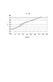
本実施形態では、図1に示されるようなカラー印刷装置の出力色空間を想定し、色変換LUTは、各軸について格子点数17、格子点間隔16、そして各色8ビット(0〜255)データで構成されるとする。
【0012】
色変換LUTの作成は以下の手順で行う。
【0013】
まず、カラー印刷装置の再現可能な色空間の頂点におけるLUT格子点、W(紙白)、RGBCMY、およびプロセスブラックBkを出力する任意の格子点を決定し、各格子点における出力構成インク色を決定する。
【0014】
次に、W(紙白)― RGBCMY、およびRGBCMY―Bkラインにおける各LUT格子点の構成インク色を決定する。
【0015】
以上の2つの手順により、カラー印刷装置の再現可能な出力色空間の最外郭を決定する。
【0016】
W(紙白)−Bkラインにおける各LUT格子点列における構成インク色を決定する。
【0017】
そして、最外郭における任意のLUT格子点列の構成インク色およびW(紙白)−Bkラインにおける格子点列の構成インク色を用いて、補間処理を行い、任意のLUT内部格子点の出力を決定する。
【0018】
本実施形態では、Kインク量および下色除去量を制御して、以下の効果を得られるようにするものである。
【0019】
(1)明度の高い領域において粒状感が生じないようにする
(2)カラー印刷装置の色再現範囲をできるだけ利用する
(3)色の連続性を保つ
【0020】
以下に、Kインク量および下色除去量を制御して色変換LUTの格子点データを作成する方法、すなわち、RGBCMY―Bkラインにおける各LUT格子点の構成インク色を決定する方法を説明する。上記効果を得るためには、特に、R、G、B、C、M、YとKを結んだライン上の格子点における構成インクの決定が重要である。
【0021】
代表例として、R(レッド)からプロセスブラックまでの出力LUT格子点列における構成インクの決定について、以下、図2、図3、図4に示されるフローチャートを用いて説明する。なお、GBCMY各色からプロセスブラックまでの構成インク量の決定も同様の手順によって決定することができる。
【0022】
図1に示されるR(レッド)からBk(プロセスブラック)を結ぶ有彩色―無彩色ライン上の格子点群を、処理対象の格子点列として定義する。
【0023】
R―Bkを結ぶ各LUT格子点列を、CMYK各濃淡インク構成の構成に基づき、有彩色インクと補色淡インク量で定義される領域(図8、領域0)、有彩色インクと補色濃淡インク量で定義される領域(領域1)、有彩色インクと補色濃インク量で定義される領域(領域2)、有彩色インクと補色濃インク量およびKインクで定義される領域(領域3)、有彩色インクとKインク(補色濃インク量=0)で定義される領域(領域4)に分割する。
【0024】
(第1の処理)
有彩色インクと補色淡インク量で定義される領域におけるCMYKインク量決定方法について図2において示されるフローチャートを用いて説明する。
【0025】
Kインクのドットが要因である粒状性に注目し、この粒状性が視覚的に判別不可能となる最大補色濃インク量と、カラー印刷装置における総インク載り量制限条件Vlim、および総インク載り量制限条件を満たす有彩色インク量があらかじめ定義されているものとする。
【0026】
さらに、CMYRGB各有彩色インクについて、それぞれ補色となるインク色の濃インク入力開始における、補色濃インクのドットが要因となる粒状性に注目し、この粒状性が視覚的に判別不可能となる最大補色淡インク量と、カラー印刷装置における総インク載り量制限条件を満たす、有彩色インク量があらかじめ定義されているものとする。
【0027】
任意のY濃インク量とM濃インク量によって構成される有彩色Rインクに対して、補色淡インク量である淡シアンインク量Clを定義する。
【0028】
上記ラインにおいて補色インク量は、有彩色インク量より少なくなる。よって、補色インク量がグレイ成分を示すこととなる。よって、本実施形態では補色インク量をグレイ成分インク量とも呼称する。
【0029】
また、有彩色Rインク量の最大値Rmは、LUTにおける頂点色であるRを実現する。
【0030】
ステップ201において、淡シアンインク量Cl=0に定義する。
【0031】
ステップ202において、有彩色Rインク量Rgを有彩色Rインク量の最大値Rmに定義する。
【0032】
ステップ203において、淡シアンインク量Clと、有彩色Rインク量Rgにおけるインク載り量Vを求める。
【0033】
ステップ204において、ステップ203におけるインク載り量Vをカラー印刷装置における総インク載り量制限条件Vlimと比較する。
【0034】
条件を満足する場合は、ステップ206において淡シアンインク量Clにおける有彩色Rインク量Rgのインク組み合わせを保存する。
【0035】
ステップ207において淡シアンインク量Clをインクリメントする。
【0036】
ステップ208において、淡シアンインク量Clが前記定義されている最大補色淡インク量Clmになると判断されるまで、ステップ202以下の処理を繰り返す。
【0037】
ステップ204において条件を満足しなかった場合は、ステップ205において有彩色Rインク量Rgを、条件を満たすまで減少させる。
【0038】
図2に示されるフローチャート処理における結果例は、図6に示されるグラフの領域Area0のようになる。
【0039】
(第2の処理)
有彩色インクと補色濃淡インク量で定義される領域(図8、領域1、領域2)におけるCMYKインク量決定方法について図3において示されるフローチャートを用いて説明する。
【0040】
任意のY濃インク量とM濃インク量によって構成される有彩色Rインクに対して、補色濃インク量であるシアンインク量Cr、補色淡インク量であるシアンインク量Clを定義する。
【0041】
ステップ301において、補色淡シアンインク量Cl=Clmを定義する。
【0042】
ステップ302において、補色濃インク量Cr=0を定義する。
【0043】
ステップ303において、有彩色Rインク量Rgを有彩色Rインク量の最大値Rmを定義する。
【0044】
以降、補色濃インク量は、補色濃インク量最大値Crmまで線形に増加される。
【0045】
補色淡シアンインク量Clにおいて、補色シアンインク量の最大値Cllim、および、γlパラメータによって、定義されるが、補色濃インク量の値に対して、補色インクにおける0値(終点)が任意パラメータlimitLによって定義される。よって、次のような式によって補色淡シアンインク量Clが定義される。
【0046】
Cl = Cllim・(1−Fli(Cr、γl、limitL))… (3.1)
【0047】
ステップ304において、前記式(3.1)によって淡シアンインク量Clを定義する。
【0048】
ステップ305において、淡シアンインク量Cl、濃シアンインク量Cr、有彩色Rインク量Rgにおけるインク載り量Vを求める。
【0049】
ステップ306において、ステップ305におけるインク載り量Vをカラー印刷装置における総インク載り量制限条件Vlimと比較する。
【0050】
条件を満足する場合は、ステップ308において、淡シアンインク量Cl、濃シアンインク量Cr、有彩色Rインク量Rgのインク組み合わせを保存する。
【0051】
ステップ309において濃シアンインク量Crをインクリメントする。
【0052】
ステップ310において、濃シアンインク量Crが最大濃シアンインク量Crmになると判断されるまで、ステップ303以下の処理を繰り返す。
【0053】
ステップ306において、条件を満足しなかった場合は、ステップ307において有彩色Rインク量Rgを、条件を満たすまで減少させる。
【0054】
図3に示されるフローチャート処理における結果例は、図6に示されるグラフの領域1,領域2のようになる。
【0055】
(第3の処理)
有彩色インクと補色濃インク量、およびKインクで定義される領域、有彩色インクとKインク(補色濃インク量=0)で定義される領域におけるCMYK濃淡インク量決定方法について図4のフローチャートを用いて説明する。
【0056】
ステップ401において、補色濃シアンインク量Cr=Crmを定義する。
【0057】
ステップ402において、有彩色Rインク量Rkを有彩色Rインク量の最大値Rmを定義する。
【0058】
ステップ403において、Kインク量K=0を定義する。
【0059】
以降、Kインクは、Kインク量最大値まで線形に増加される。
【0060】
一方、有彩色Rインク量Rkは、有彩色Rインク量の最大値Rm、Kインク量Kおよび、γrパラメータを持つ次の式によって定義される。
【0061】
Rk =Rm・(1−(K/255)γr)… (4.1)
【0062】
補色濃シアンインク量Crは、補色シアンインク量の最大値Crm、および、γcパラメータ、および補色インクの0値(終点)を示すパラメータlimitRを持つ次の式によって定義される。
【0063】
Cr = Crm・(1−Fr(K、γc、limitR))… (4.2)
【0064】
ステップ404において、Kインク量K、および前記式(4.2)によって濃シアンインク量Crを定義する。
【0065】
ステップ405において、前記式(4.1)によって有彩色Rインク量Rkを定義する。
【0066】
ステップ406において、Kインク量K、濃シアンインク量Cr、有彩色Rインク量Rkにおけるインク載り量Vを求める。
【0067】
ステップ407において、ステップ404におけるインク載り量Vをカラー印刷装置におけるCMYK総インク載り量制限条件Vlimと比較する。
【0068】
条件を満足する場合は、ステップ409において、Kインク量K、シアンインク量Crにおける有彩色Rインク量Rkのインク組み合わせを保存する。
【0069】
ステップ410においてKインク量Kをインクリメントする。
【0070】
ステップ411において、Kインク量Kが最大Kインク量になると判断されるまで、ステップ404以下の処理を繰り返す。
【0071】
ステップ407において、条件を満足しなかった場合は、ステップ408において有彩色Rインク量Rkを、条件を満たすまで減少させる。
【0072】
図4に示されるフローチャート処理における結果例は、図6に示されるグラフの領域3、領域4のようになる。
【0073】
図2〜図4のフローチャート処理によって求められた、CMYK各濃淡インク量を定義したインク量組み合わせから、任意点数のインク組み合わせを選択し、カラー印刷装置によって前記選択されたインク組み合わせにおけるパッチを出力、測色を行う。
【0074】
その結果例を、図8、図9に示す。
【0075】
図8、図9においては、前記式(3.1)および前記式(4.2)によって定義される淡シアンインク量Clと濃シアンインク量Crと、前記式(3.1)によって定義される有彩色Rインク量Rkについて、前記式(3.1)前記式(4.1)前記式(4.2)における各パラメータを3種類変更した結果を示している。
【0076】
よって、図8、図9をみても明らかなように、有彩色インクと補色淡インク量で定義される領域と、有彩色インクと補色濃淡インク量で定義される領域と、有彩色インクと補色濃インク量で定義される領域と、有彩色インクと補色濃インク量およびKインクで定義される領域、有彩色インクとKインク(補色インク量=0)で定義される領域に関しては、再現色空間が最大であり、かつ、各領域を滑らかに結ぶための前記式(3.1)前記式(4.1)前記式(4.2)における各パラメータは一意に決定することが可能である。
【0077】
よって、再現色空間が最大であり、かつ、階調性が高く、各領域を滑らかに結ぶための前記式(3.1)前記式(4.1)前記式(4.2)における各パラメータを決定することができる。
【0078】
(第4の処理)
決定された各パラメータにおけるCMYK各濃淡インク量において、選択された任意点数のインク組み合わせについて、パッチを形成し測色することにより、色再現空間内における各3次元座標値を求める。
【0079】
上記手順によって決定された各パラメータにおけるCMYK各濃淡インク量に基づきLUT格子点にCMYK各濃淡インク量を定義するための処理を、図5に示されるフローチャートを用いて説明する。
【0080】
ステップ501において、色変換LUTにおけるR−Bk上における任意数N点について、CMYK各インク量と色再現空間内における3次元座標値を定義する。この時、図6に示される領域0、領域1、領域2 、領域3、領域4の境界における各CMYK各濃淡インク量はN点に含まれる。
【0081】
ステップ502において、Bk点を原点0とし、3次元間距離L(0)=0と定義する。
【0082】
ステップ503において、前記任意数点nについて隣合う点(n-1)における3次元間距離L(n)をそれぞれ求める。
【0083】
3次元空間がLab空間であった場合、次に示される式によって求められる。
【0084】
【外1】

ステップ504において、Bk点を原点とし、Rまでの距離L(R)を、ステップにおいて求められた各点間の3次元間距離の総和として求める。
【0086】
L(R)=ΣL(n) (n=0…N)
【0087】
ステップ505において、色再現空間内における各3次元座標値より、領域0の距離L(Gl)を求め、距離L(R)に対する比率を求める。
【0088】
ステップ506において、領域1の距離L(Glr)を求め、距離L(R)に対する比率を求める。
【0089】
ステップ507において、領域2の距離L(Gr)を求め、距離L(R)に対する比率を求める。
【0090】
ステップ508において、領域3の距離L(GK) を求め、距離L(R)に対する比率を求める。
【0091】
ステップ509において、領域4の距離L(BK) を求め、距離L(R)に対する比率を求める。
【0092】
ステップ510において、各領域の距離と距離L(R)の比例に応じて、各領域間を再現するLUT格子点数を配分する。
【0093】
ステップ511において、各領域の境界となるLUT格子点に対して、各領域の境界となるCMYK濃淡インク量を定義する。
【0094】
ステップ512において、各領域間の距離として定義された距離L(Gl)、 L(Glr)、 L(Gr)、L(GK)、 L(BK)を配分された格子点数で等分し、各領域間のLUT格子点間の距離を求める。
【0095】
ステップ513において、R−Bk格子点列において、Bkを原点として、注目LUT格子点をBkLUT格子点から1格子点R側にシフトした格子点に定義する。
【0096】
ステップ514において、注目LUT格子点における原点Bkからの格子点間距離を、ステップ512において求められた各領域におけるLUT格子点間距離より求める。
【0097】
ステップ515において、定義された注目LUT格子点における原点Bkからの格子点間距離を間にはさむステップ501において定義されたCMYK各濃淡インク量の組み合わせおよびその原点Bkからの各距離から、注目LUT格子点におけるCMYK各濃淡インク量を、距離に基づく線形補間処理により求める。
【0098】
ステップ516において、注目格子点をひとつR側にシフトする。
【0099】
ステップ517において、R―Bk格子点列におけるすべての格子点において、CMYK各濃淡インク量を定義するまでステップ514からステップ517の処理を繰り返す。
【0100】
以上、図2から図5までに示されたフローチャートによる処理を行うことにより、定義されたLUT格子点列に関して、カラー印刷装置の出力再現色空間が可能な限り最大であり、および階調再現性のよい画像出力を実現する色変換ルックアップテーブルを作成することを実現する。
【0101】
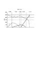
図2から図5までに示されたフローチャートによる処理の結果例を図7にて示す。
【0102】
本実施形態によれば、第1の処理により、明度の高い領域において粒状感が生じないようにすることができる。さらに、第1〜第3の処理によりカラー印刷装置の色再現範囲を最大限利用することができる。また、第1〜第4の処理により、色の連続性を保つことができる。
【0103】
(実施形態2)
カラー印刷装置内にて用いられる色変換ルックアップテーブルの作成についてのみならず、カラー印刷装置に接続されたホストコンピュータ内において、色変換処理を行った画像出力結果をカラー印刷装置に送るようなシステムにおいて、ホストコンピュータ内において色変換に用いられるルックアップテーブルの作成においても本発明を適用できることは明らかである。
【0104】
また前述した実施形態の機能を実現する様に各種のデバイスを動作させる様に該各種デバイスと接続された装置あるいはシステム内のコンピュータに、前記実施形態機能を実現するためのソフトウエアのプログラムコードを供給し、そのシステムあるいは装置のコンピュータ(CPUあるいはMPU)を格納されたプログラムに従って前記各種デバイスを動作させることによって実施したものも本発明の範疇に含まれる。
【0105】
またこの場合、前記ソフトウエアのプログラムコード自体が前述した実施形態の機能を実現することになり、そのプログラムコード自体、及びそのプログラムコードをコンピュータに供給するための手段、例えばかかるプログラムコードを格納した記憶媒体は本発明を構成する。
【0106】
かかるプログラムコードを格納する記憶媒体としては例えばフロッピーディスク、ハードディスク、光ディスク、光磁気ディスク、CD-ROM,、磁気テープ、不揮発性のメモリカード、ROM等を用いることが出来る。
【0107】
またコンピュータが供給されたプログラムコードを実行することにより、前述の実施形態の機能が実現されるだけではなく、そのプログラムコードがコンピュータにおいて稼働しているOS(オペレーティングシステム)、あるいは他のアプリケーションソフト等と共同して前述の実施形態の機能が実現される場合にもかかるプログラムコードは本発明の実施形態に含まれることは言うまでもない。
【0108】
更に供給されたプログラムコードが、コンピュータの機能拡張ボードやコンピュータに接続された機能拡張ユニットに備わるメモリに格納された後そのプログラムコードの指示に基づいてその機能拡張ボードや機能格納ユニットに備わるCPU等が実際の処理の一部または全部を行い、その処理によって前述した実施形態の機能が実現される場合も本発明に含まれることは言うまでもない。
【0109】
【発明の効果】
本発明によれば、粒状感がなく高品質な出力画像を得ることができるようにすることができる。
【図面の簡単な説明】
【図1】カラー印刷装置の出力色空間と色空間を再現するためのルックアップテーブル格子点の関係を示した図である。
【図2】第1の処理の流れを示したフローチャートである。
【図3】第2の処理の流れを示したフローチャートである。
【図4】第3の処理の流れを示したフローチャートである。
【図5】第4の処理の流れを示したフローチャートである。
【図6】第1および第2の処理結果例を示した図である。
【図7】第3の処理結果例を示した図である。
【図8】本実施形態において補色インクと有彩色インクを求める式のパラメータを変えた時の縦軸L*、横軸クロマ(彩度)によって示されるカラー印刷装置における再現色空間について比較結果を示した図である。
【図9】本実施形態において補色インクと有彩色インクを求める式のパラメータを変えた時の縦軸b*、横軸a*によって示されるカラー印刷装置における再現色空間について比較結果を示した図である。[0001]
BACKGROUND OF THE INVENTION
The present invention also relates to creating a color conversion lookup table for a color image forming apparatus that forms a color image using a black recording material and a plurality of recording materials having different densities used for color reproduction of the same system.
[0002]
[Prior art]
The color printing apparatus has a color conversion lookup table (LUT) that inputs RGB signal values from an application in a PC and outputs CMYK signal values.
[0003]
In recent years, in order to obtain a printer output that is the same color as the input signal RGB, an LUT that converts the input signal RGB value to device-dependent RGB (RGB that depends on the color printing apparatus), and the device-dependent RGB value is converted to a CMYK output value. A color conversion LUT that converts input RGB signal values into CMYK output values has been proposed.
[0004]
[Problems to be solved by the invention]
Conventionally, the K ink amount and the under color removal amount at the grid point of the color conversion LUT that converts the device-dependent RGB values into CMYK output values are obtained by calculation based on a function.
[0005]
Since the function using the minimum value of each CMY or the K ink amount as a parameter is used as a function, it is difficult to control the K ink amount. For this reason, in high-lightness output, the K ink dots may cause graininess to the output image, which may cause the image quality of the output image to deteriorate.
[0006]
In addition to the undercolor removal function, 3D interpolation such as tetrahedral interpolation is performed using L * a * b * from the color conversion LUT created by the masking calculation method and the 3D printer model color reproduction space. A method for searching for a desired CMYK ink amount has also been proposed. However, these methods require enormous calculation time and have problems such as variations in the gradation of output results, and it can be said that the output color space in a color printing apparatus is not necessarily reproduced to the maximum. In other words, it may not be said that the color reproducibility is sufficient for the RGB signal color space as the input signal.
[0007]
Also, if the maximum density of the K ink itself is light, or if the maximum output value of only K ink is set in process black, the chromatic color ink, K ink, and chromatic color ink are complementary to those of process black. The output density due to the combination of the three ink systems used as inks is higher, causing problems in the color printing apparatus, such as causing distortion in the output color space and generating pseudo contours in the output image.
[0008]
An object of the present invention is to make it possible to obtain a high-quality output image without graininess.
[0009]
[Means for Solving the Problems]
In order to achieve the above object, the present invention creates a color conversion lookup table for a color image forming apparatus that forms a color image using a plurality of recording materials including a dark recording material and a light recording material for the same color. A color processing method for generating a color conversion lookup table that converts an input signal into a plurality of color components including a black component; A color processing method for determining a start point that defines an amount of the dark recording material between vertices representing chromatic colors and vertices representing black, wherein the dark recording corresponding to a complementary color component of the chromatic color in an output image Enter the maximum amount of light recording material indicating the amount of the light recording material corresponding to the complementary color component, in which the graininess of the material is inconspicuous, input the total recording material loading amount restriction condition, and the total recording material loading amount restriction condition Based on From the amount that maximizes the recording material corresponding to the chromatic color between the vertices, the amount of recording material corresponding to the chromatic color is decreased, and from the amount that minimizes the light recording material between the vertices The amount of the light recording material is increased, the amount of the recording material corresponding to the chromatic color after the decrease and the amount of the light recording material after the increase are defined, and the amount of the light recording material becomes the maximum light recording material amount The above definition is repeated until a plurality of colorimetric values obtained by measuring a plurality of patch images formed using the respective amounts of the recording materials obtained by repeating the definition are input, and the definition is repeated. The start point is determined on the basis of the obtained amounts of the recording materials and the distances of the inputted plurality of colorimetric values in the color space. A color processing apparatus for creating a color conversion lookup table for a color image forming apparatus that forms a color image using a plurality of recording materials including a dark recording material and a light recording material for the same color, the input signal When creating the color conversion look-up table for converting a plurality of color components including a black component, a vertex indicating a chromatic color and a vertex indicating black in the reproducible color space of the color image forming apparatus. A color processing apparatus for determining a starting point that defines an amount of the dark recording material between the vertices of the complementary color, wherein the graininess of the dark recording material corresponding to the complementary color component of the chromatic color in the output image is inconspicuous A maximum light recording material amount input means for inputting the maximum light recording material amount indicating the amount of the light recording material corresponding to the component, a condition input means for inputting a total recording material loading amount restriction condition, and the total recording material loading amount Restriction The amount of the recording material corresponding to the chromatic color is reduced from the amount that maximizes the recording material corresponding to the chromatic color between the vertices, and the light recording material is minimized between the vertices. The amount of the light recording material is increased from the amount to be defined, the definition means for defining the amount of the recording material corresponding to the chromatic color after the decrease and the amount of the light recording material after the increase, and the amount of the light recording material is the amount of the light recording material Repeating means for repeating the definition until reaching the maximum light recording material amount, and a plurality of colorimetry obtained by measuring a plurality of patch images formed using the respective amounts of the recording materials obtained by repeating the definition The start point is determined based on the colorimetric value input means for inputting a value, the amount of each recording material obtained by repeating the definition, and the distances of the input colorimetric values in the color space. Decisive factor to Characterized in that it has and.
[0010]
DETAILED DESCRIPTION OF THE INVENTION
(First embodiment)
A method for creating a color conversion LUT (look-up table) for converting device RGB into output ink corresponding color signals in a multicolor printing apparatus using CMYK dark ink and light ink diluted for at least one color as output ink will be described.
[0011]
In this embodiment, assuming an output color space of a color printing apparatus as shown in FIG. 1, the color conversion LUT has 17 grid points for each axis, 16 grid point intervals, and 8 bits (0 to 255) data for each color. It is assumed that
[0012]
The color conversion LUT is created according to the following procedure.
[0013]
First, the LUT grid point at the apex of the reproducible color space of the color printer, W (paper white), RGBCMY, and arbitrary grid points that output process black Bk are determined, and the output constituent ink color at each grid point is determined. decide.
[0014]
Next, the constituent ink color of each LUT lattice point in the W (paper white) -RGBCMY and RGBCMY-Bk lines is determined.
[0015]
The outermost contour of the reproducible output color space of the color printing apparatus is determined by the above two procedures.
[0016]
The constituent ink color in each LUT lattice point sequence in the W (paper white) -Bk line is determined.
[0017]
Then, interpolation processing is performed using the constituent ink color of an arbitrary LUT lattice point sequence in the outermost contour and the constituent ink color of the lattice point sequence in the W (paper white) -Bk line, and an output of an arbitrary internal LUT lattice point is output. decide.
[0018]
In the present embodiment, the following effects are obtained by controlling the K ink amount and the under color removal amount.
[0019]
(1) Prevent graininess in areas with high brightness (2) Use the color reproduction range of the color printing device as much as possible (3) Maintain color continuity
In the following, a method of controlling the K ink amount and the under color removal amount to create grid point data of the color conversion LUT, that is, a method of determining the constituent ink color of each LUT lattice point in the RGBCMY-Bk line will be described. In order to obtain the above effect, it is particularly important to determine the constituent inks at the lattice points on the line connecting R, G, B, C, M, Y and K.
[0021]
As a representative example, determination of constituent inks in an output LUT lattice point sequence from R (red) to process black will be described below with reference to flowcharts shown in FIGS. It should be noted that the amount of constituent ink from each GBCMY color to process black can also be determined by the same procedure.
[0022]
A grid point group on the chromatic-achromatic line connecting R (red) and Bk (process black) shown in FIG. 1 is defined as a grid point sequence to be processed.
[0023]
Based on the configuration of each CMYK dark and light ink configuration, each LUT grid point connecting R-Bk is defined by an area defined by the amount of chromatic color ink and complementary color light ink (FIG. 8, area 0), chromatic color ink and complementary color light and dark ink. A region defined by the amount (region 1), a region defined by the chromatic ink and the complementary dark ink amount (region 2), a region defined by the chromatic ink and the complementary dark ink amount, and the K ink (region 3), The area is divided into areas (area 4) defined by chromatic ink and K ink (complementary dark ink amount = 0).
[0024]
(First process)
A CMYK ink amount determination method in an area defined by the chromatic color ink and the complementary color light ink amount will be described with reference to the flowchart shown in FIG.
[0025]
Paying attention to the graininess caused by the K ink dots, the maximum complementary dark ink amount that makes this graininess visually indistinguishable, the total ink applied amount limiting condition Vlim in the color printing apparatus, and the total ink applied amount It is assumed that the amount of chromatic color ink that satisfies the limit is defined in advance.
[0026]
In addition, for each chromatic color ink of CMYRGB, pay attention to the graininess caused by the dots of complementary dark ink at the start of dark ink input of complementary ink colors, and this graininess cannot be visually discriminated at the maximum. It is assumed that the complementary color light ink amount and the chromatic color ink amount that satisfy the total ink applied amount restriction condition in the color printing apparatus are defined in advance.
[0027]
For a chromatic color R ink composed of an arbitrary Y dark ink amount and M dark ink amount, a light cyan ink amount Cl which is a complementary light ink amount is defined.
[0028]
In the above line, the complementary color ink amount is smaller than the chromatic color ink amount. Therefore, the complementary color ink amount indicates the gray component. Therefore, in this embodiment, the complementary color ink amount is also referred to as a gray component ink amount.
[0029]
Further, the maximum value Rm of the chromatic color R ink amount realizes R which is a vertex color in the LUT.
[0030]
In
[0031]
In
[0032]
In
[0033]
In
[0034]
If the condition is satisfied, in
[0035]
In
[0036]
In
[0037]
If the condition is not satisfied in
[0038]
An example of the result of the flowchart processing shown in FIG. 2 is a graph area Area0 shown in FIG.
[0039]
(Second process)
A CMYK ink amount determination method in the region defined by the chromatic color ink and the complementary color density ink amount (FIG. 8,
[0040]
For a chromatic color R ink composed of an arbitrary Y dark ink amount and M dark ink amount, a cyan ink amount Cr as a complementary dark ink amount and a cyan ink amount Cl as a complementary light ink amount are defined.
[0041]
In
[0042]
In
[0043]
In
[0044]
Thereafter, the complementary dark ink amount is increased linearly up to the complementary color dark ink amount maximum value Crm.
[0045]
The complementary color light cyan ink amount Cl is defined by the maximum value of the complementary color cyan ink amount Cllim and the γl parameter, but the 0 value (end point) in the complementary color ink is an optional parameter limitL with respect to the value of the complementary dark ink amount. Defined by Therefore, the complementary color light cyan ink amount Cl is defined by the following equation.
[0046]
Cl = Cllim · (1-Fli (Cr, γl, limitL)) (3.1)
[0047]
In
[0048]
In
[0049]
In
[0050]
If the condition is satisfied, in
[0051]
In
[0052]
In
[0053]
If the condition is not satisfied in
[0054]
An example of the result in the flowchart processing shown in FIG. 3 is as shown in
[0055]
(Third process)
FIG. 4 is a flowchart of a CMYK dark and light ink amount determination method in an area defined by chromatic color ink and complementary dark ink amount and K ink, and an area defined by chromatic color ink and K ink (complementary dark ink amount = 0). It explains using.
[0056]
In
[0057]
In
[0058]
In
[0059]
Thereafter, the K ink is linearly increased to the K ink amount maximum value.
[0060]
On the other hand, the chromatic color R ink amount Rk is defined by the following equation having the maximum value Rm of the chromatic color R ink amount, the K ink amount K, and the γr parameter.
[0061]
Rk = Rm. (1- (K / 255) γr) (4.1)
[0062]
The complementary dark cyan ink amount Cr is defined by the following equation having the maximum value Crm of the complementary cyan ink amount, the γc parameter, and the parameter limitR indicating the 0 value (end point) of the complementary color ink.
[0063]
Cr = Crm · (1-Fr (K, γc, limitR)) (4.2)
[0064]
In
[0065]
In step 405, the chromatic color R ink amount Rk is defined by the equation (4.1).
[0066]
In
[0067]
In
[0068]
If the condition is satisfied, in
[0069]
In
[0070]
In
[0071]
If the condition is not satisfied in
[0072]
An example of the result in the flowchart processing shown in FIG. 4 is as shown in region 3 and region 4 of the graph shown in FIG.
[0073]
2 to 4, an arbitrary number of ink combinations are selected from the ink amount combinations that define the respective CMYK dark and light ink amounts obtained by the flowchart processing of FIGS. 2 to 4, and a patch in the selected ink combination is output by the color printing apparatus, Perform colorimetry.
[0074]
Examples of the results are shown in FIGS.
[0075]
In FIGS. 8 and 9, the light cyan ink amount Cl and the dark cyan ink amount Cr defined by the equations (3.1) and (4.2), and the chromatic color R defined by the equation (3.1). With respect to the ink amount Rk, the results obtained by changing three types of parameters in the equation (3.1), the equation (4.1), and the equation (4.2) are shown.
[0076]
Accordingly, as is apparent from FIGS. 8 and 9, the region defined by the chromatic color ink and the complementary color light ink amount, the region defined by the chromatic color ink and the complementary color dark ink amount, the chromatic color ink and the complementary color. For areas defined by dark ink amount, areas defined by chromatic ink and complementary dark ink amount and K ink, and areas defined by chromatic color ink and K ink (complementary ink amount = 0), reproduction color Each parameter in the equation (3.1), the equation (4.1), and the equation (4.2) for smoothly connecting the respective areas can be uniquely determined.
[0077]
Therefore, each parameter in the equation (3.1), the equation (4.1), and the equation (4.2) for smoothly connecting each region can be determined with the maximum reproduction color space and high gradation. .
[0078]
(Fourth process)
The three-dimensional coordinate values in the color reproduction space are determined by forming a patch and measuring the color of the selected combination of inks at any number of dark and light CMYK ink amounts for each parameter.
[0079]
A process for defining the CMYK density ink amounts at the LUT lattice points based on the CMYK density ink amounts in the parameters determined by the above procedure will be described with reference to the flowchart shown in FIG.
[0080]
In
[0081]
In
[0082]
In step 503, the three-dimensional distance L (n) at the adjacent point (n-1) with respect to the arbitrary number n is obtained.
[0083]
When the three-dimensional space is Lab space, it is obtained by the following equation.
[0084]
[Outside 1]
In
[0086]
L (R) = ΣL (n) (n = 0… N)
[0087]
In
[0088]
In
[0089]
In
[0090]
In step 508, the distance L (GK) of the region 3 is obtained, and the ratio to the distance L (R) is obtained.
[0091]
In
[0092]
In step 510, the number of LUT lattice points to be reproduced between the regions is distributed according to the proportion of the distance between the regions and the distance L (R).
[0093]
In step 511, CMYK dark and light ink amounts that define the boundaries of the regions are defined for the LUT lattice points that serve as the boundaries of the regions.
[0094]
In
[0095]
In step 513, in the R-Bk lattice point sequence, the target LUT lattice point is defined as a lattice point shifted from the BkLUT lattice point to the one lattice point R side with Bk as the origin.
[0096]
In
[0097]
In
[0098]
In
[0099]
In
[0100]
As described above, by performing the processing according to the flowcharts shown in FIGS. 2 to 5, the output reproduction color space of the color printing apparatus is as large as possible with respect to the defined LUT lattice point sequence, and the gradation reproducibility. It is possible to create a color conversion lookup table that realizes a good image output.
[0101]
FIG. 7 shows an example of the result of the processing according to the flowcharts shown in FIGS.
[0102]
According to the present embodiment, it is possible to prevent graininess from occurring in a region with high brightness by the first processing. Furthermore, the color reproduction range of the color printing apparatus can be utilized to the maximum by the first to third processes. In addition, color continuity can be maintained by the first to fourth processes.
[0103]
(Embodiment 2)
A system that not only creates a color conversion lookup table used in a color printing apparatus but also sends an image output result of color conversion processing to the color printing apparatus in a host computer connected to the color printing apparatus. However, it is obvious that the present invention can be applied to the creation of a lookup table used for color conversion in the host computer.
[0104]
In addition, a program code of software for realizing the functions of the embodiment is provided to an apparatus or a computer in the system connected to the various devices so as to operate the various devices so as to realize the functions of the above-described embodiments. What is implemented by operating the various devices according to a program stored in the computer (CPU or MPU) of the system or apparatus supplied is also included in the scope of the present invention.
[0105]
In this case, the software program code itself realizes the functions of the above-described embodiments, and the program code itself and means for supplying the program code to the computer, for example, the program code are stored. The storage medium constitutes the present invention.
[0106]
As a storage medium for storing the program code, for example, a floppy disk, a hard disk, an optical disk, a magneto-optical disk, a CD-ROM, a magnetic tape, a nonvolatile memory card, a ROM, or the like can be used.
[0107]
Further, by executing the program code supplied by the computer, not only the functions of the above-described embodiments are realized, but also the OS (operating system) in which the program code is running on the computer, or other application software It goes without saying that the program code is also included in the embodiment of the present invention even when the functions of the above-described embodiment are realized in cooperation with the embodiment.
[0108]
Further, after the supplied program code is stored in the memory provided in the function expansion board of the computer or the function expansion unit connected to the computer, the CPU provided in the function expansion board or function storage unit based on the instruction of the program code However, it is needless to say that the present invention also includes a case where the function of the above-described embodiment is realized by performing part or all of the actual processing.
[0109]
【The invention's effect】
According to the present invention, it is possible to obtain a high-quality output image without graininess.
[Brief description of the drawings]
FIG. 1 is a diagram illustrating a relationship between an output color space of a color printing apparatus and look-up table grid points for reproducing a color space.
FIG. 2 is a flowchart showing a flow of first processing.
FIG. 3 is a flowchart showing a flow of second processing.
FIG. 4 is a flowchart showing a flow of third processing.
FIG. 5 is a flowchart showing a flow of a fourth process.
FIG. 6 is a diagram showing an example of first and second processing results.
FIG. 7 is a diagram illustrating an example of a third processing result.
FIG. 8 shows a comparison result of the reproduction color space in the color printing apparatus indicated by the vertical axis L * and the horizontal axis chroma (saturation) when the parameters of the equations for obtaining complementary color ink and chromatic color ink are changed in the present embodiment. FIG.
FIG. 9 is a diagram showing a comparison result of a reproduction color space in the color printing apparatus indicated by the vertical axis b * and the horizontal axis a * when the parameters of the equations for obtaining complementary color ink and chromatic color ink are changed in the present embodiment. It is.
Claims (7)
入力信号を、黒の成分を含む複数の色の成分に変換する前記色変換ルックアップテーブルを作成する際に、前記カラー画像形成装置の再現可能な色空間の有彩色を示す頂点と黒を示す頂点との頂点間における前記濃い記録材の量を定義する開始点を決定する色処理方法であって、
出力画像における前記有彩色の補色成分に対応する前記濃い記録材の粒状感が目立たない、前記補色成分に対応する前記淡い記録材の量を示す最大淡記録材量を入力し、
総記録材載り量制限条件を入力し、
前記総記録材載り量制限条件に基づき、前記頂点間において前記有彩色に対応する記録材を最大とする量から前記有彩色に対応する記録材の量を減少させ、かつ、前記頂点間において前記淡い記録材を最小とする量から前記淡い記録材の量を増加させ、減少後の前記有彩色に対応する記録材および増加後の前記淡い記録材それぞれの量を定義し、
前記淡い記録材の量が前記最大淡記録材量になるまで前記定義を繰り返し、
前記定義を繰り返して得られた記録材それぞれの量を用いて形成された複数のパッチ画像を測色して得られる複数の測色値を入力し、
前記定義を繰り返して得られた記録材それぞれの量と前記入力した複数の測色値の前記色空間におけるそれぞれの距離とに基づき、前記開始点を決定することを特徴とする色処理方法。A color processing method for creating a color conversion lookup table for a color image forming apparatus that forms a color image using a plurality of recording materials including a dark recording material and a light recording material for the same color,
An input signal, when creating the color conversion lookup table for converting the components of a plurality of colors including a black component shows a vertex and black indicating the chromatic reproducible color space of the color image forming apparatus a color processing method for determining the starting point for defining the amount of the dark recording material between the vertex of the vertex,
Graininess of the dark recording material is inconspicuous corresponding to complementary color component of definitive the chromatic color output image, and inputs the maximum light quantity of recording material that shows the amount of the light recording material corresponding to the complementary color components,
Enter the total recording material loading limit condition,
Based on the total recording material loading amount restriction condition, the amount of the recording material corresponding to the chromatic color is reduced from the amount that maximizes the recording material corresponding to the chromatic color between the vertices, and Increase the amount of the light recording material from the amount that minimizes the light recording material, define the amount of the recording material corresponding to the chromatic color after the decrease and the amount of the light recording material after the increase,
The above definition is repeated until the amount of the light recording material reaches the maximum light recording material amount,
Input a plurality of colorimetric values obtained by measuring a plurality of patch images formed using the amounts of the respective recording materials obtained by repeating the definition,
A color processing method , wherein the start point is determined based on the amount of each recording material obtained by repeating the definition and the distances of the inputted plurality of colorimetric values in the color space .
入力信号を、黒の成分を含む複数の色の成分に変換する前記色変換ルックアップテーブルを作成する際に、前記カラー画像形成装置の再現可能な色空間の有彩色を示す頂点と黒を示す頂点との頂点間における前記濃い記録材の量を定義する開始点を決定する色処理装置であって、
出力画像における前記有彩色の補色成分に対応する前期濃い記録材の粒状感が目立たない、前記補色成分に対応する前記淡い記録材の量を示す最大淡記録材量を入力する最大淡記録材量入力手段と、
総記録材載り量制限条件を入力する条件入力手段と、
前記総記録材載り量制限条件に基づき、前記頂点間において前記有彩色に対応する記録材を最大とする量から、前記有彩色に対応する記録材の量を減少させ、かつ、前記頂点間において前記淡い記録材を最小とする量から前記淡い記録材の量を増加させ、減少後の前記有彩色に対応する記録材および増加後の前記淡い記録材それぞれの量を定義する定義手段と、
前記淡い記録材の量が前記最大淡記録材量になるまで前記定義を繰り返す繰り返し手段と、
前記定義を繰り返して得られた記録材それぞれの量を用いて形成された複数のパッチ画像を測色して得られる複数の測色値を入力する測色値入力手段と、
前記定義を繰り返して得られた記録材それぞれの量と前記入力した複数の測色値の前記色空間におけるそれぞれの距離とに基づき、前記開始点を決定する決定手段と
を有することを特徴とする色処理装置。A color processing apparatus for creating a color conversion lookup table for a color image forming apparatus that forms a color image using a plurality of recording materials including a dark recording material and a light recording material for the same color,
An input signal, when creating the color conversion lookup table for converting the components of a plurality of colors including a black component shows a vertex and black indicating the chromatic reproducible color space of the color image forming apparatus a color processing apparatus for determining a starting point for defining the amount of the dark recording material between the vertex of the vertex,
Graininess year dark recording material corresponding to your Keru complementary color component of the chromatic color in the output image is not conspicuous, the maximum light recording to enter the maximum light quantity of recording material that shows the amount of the light recording material corresponding to the complementary color components Material input means;
Condition input means for inputting the total recording material load limit condition,
Based on the total recording material loading amount limiting condition, the amount of the recording material corresponding to the chromatic color is reduced from the amount that maximizes the recording material corresponding to the chromatic color between the vertices, and between the vertices. Definition means for increasing the amount of the light recording material from the amount that minimizes the light recording material, and defining the amount of the recording material corresponding to the chromatic color after the decrease and the amount of the light recording material after the increase,
Repeating means for repeating the definition until the amount of the light recording material reaches the maximum light recording material amount;
A colorimetric value input means for inputting a plurality of colorimetric values obtained by measuring a plurality of patch images formed using the amounts of the respective recording materials obtained by repeating the definition;
And determining means for determining the start point based on the amounts of the recording materials obtained by repeating the definition and the distances of the input colorimetric values in the color space. Color processing device.
Priority Applications (2)
| Application Number | Priority Date | Filing Date | Title |
|---|---|---|---|
| JP2000214191A JP4310032B2 (en) | 2000-07-14 | 2000-07-14 | Color processing method, color processing apparatus and recording medium therefor |
| US09/901,612 US6995881B2 (en) | 2000-07-14 | 2001-07-11 | Image processing method and program capable of reducing graininess |
Applications Claiming Priority (1)
| Application Number | Priority Date | Filing Date | Title |
|---|---|---|---|
| JP2000214191A JP4310032B2 (en) | 2000-07-14 | 2000-07-14 | Color processing method, color processing apparatus and recording medium therefor |
Publications (3)
| Publication Number | Publication Date |
|---|---|
| JP2002033927A JP2002033927A (en) | 2002-01-31 |
| JP2002033927A5 JP2002033927A5 (en) | 2007-08-30 |
| JP4310032B2 true JP4310032B2 (en) | 2009-08-05 |
Family
ID=18709814
Family Applications (1)
| Application Number | Title | Priority Date | Filing Date |
|---|---|---|---|
| JP2000214191A Expired - Fee Related JP4310032B2 (en) | 2000-07-14 | 2000-07-14 | Color processing method, color processing apparatus and recording medium therefor |
Country Status (1)
| Country | Link |
|---|---|
| JP (1) | JP4310032B2 (en) |
Families Citing this family (1)
| Publication number | Priority date | Publication date | Assignee | Title |
|---|---|---|---|---|
| JP5615238B2 (en) * | 2011-07-12 | 2014-10-29 | 富士フイルム株式会社 | Separation condition determination apparatus, method and program |
-
2000
- 2000-07-14 JP JP2000214191A patent/JP4310032B2/en not_active Expired - Fee Related
Also Published As
| Publication number | Publication date |
|---|---|
| JP2002033927A (en) | 2002-01-31 |
Similar Documents
| Publication | Publication Date | Title |
|---|---|---|
| JP4623630B2 (en) | Image processing apparatus, image processing method, program, image forming apparatus, and image forming system | |
| US7706605B2 (en) | Color correction table forming method and apparatus, control program and storage medium | |
| US8218206B2 (en) | Color conversion using transformed gamuts | |
| US8638474B2 (en) | Image processing apparatus and color conversion table generating method | |
| JP2001216498A (en) | Method and device for processing image signal and medium with recorded image signal processing program | |
| JP2004180013A (en) | Color conversion device and color conversion method | |
| JP2005253072A (en) | System and method for gamut mapping control | |
| JP2005253072A5 (en) | ||
| JP4974853B2 (en) | Image processing apparatus, image processing method, and program | |
| JP4823051B2 (en) | Method for generating combined lookup table, image processing apparatus, and image forming apparatus | |
| US6922197B2 (en) | Method of generating color separation table | |
| JP4803122B2 (en) | Color processing apparatus and program | |
| US8773723B2 (en) | Generating color separation table for printer having color forming materials with high and low relative densities using a gamut boundary to limit use of dark color material | |
| US6995881B2 (en) | Image processing method and program capable of reducing graininess | |
| JP2007028148A (en) | Apparatus, method and program for color conversion, and recording medium | |
| JP2010074317A (en) | Image processor, image processing program, and image processing method | |
| JP2014135544A (en) | Image processing apparatus, image processing method, program, and storage medium | |
| JP2005176280A (en) | Color image processing method, color image processing apparatus, color image processing program, and storage medium | |
| JP4310032B2 (en) | Color processing method, color processing apparatus and recording medium therefor | |
| JP4215348B2 (en) | Method for converting non-printable color values into printable color values, an image reproduction system for reproducing a color image, and control means comprising color conversion means suitable for this image reproduction system | |
| JP2015035800A (en) | Image processing device, image processing method, and program | |
| JP3658286B2 (en) | Image processing method and recording medium | |
| JP4029997B2 (en) | Color conversion apparatus, color conversion method, program, and recording medium | |
| JP4524578B2 (en) | Image processing apparatus, image processing method, program, and recording medium | |
| JP4101741B2 (en) | Image processing apparatus, image forming apparatus, image processing method, image processing program, and recording medium |
Legal Events
| Date | Code | Title | Description |
|---|---|---|---|
| A521 | Written amendment |
Free format text: JAPANESE INTERMEDIATE CODE: A523 Effective date: 20070711 |
|
| A621 | Written request for application examination |
Free format text: JAPANESE INTERMEDIATE CODE: A621 Effective date: 20070711 |
|
| A977 | Report on retrieval |
Free format text: JAPANESE INTERMEDIATE CODE: A971007 Effective date: 20080822 |
|
| A131 | Notification of reasons for refusal |
Free format text: JAPANESE INTERMEDIATE CODE: A131 Effective date: 20080924 |
|
| A521 | Written amendment |
Free format text: JAPANESE INTERMEDIATE CODE: A523 Effective date: 20081125 |
|
| TRDD | Decision of grant or rejection written | ||
| A01 | Written decision to grant a patent or to grant a registration (utility model) |
Free format text: JAPANESE INTERMEDIATE CODE: A01 Effective date: 20090428 |
|
| A01 | Written decision to grant a patent or to grant a registration (utility model) |
Free format text: JAPANESE INTERMEDIATE CODE: A01 |
|
| A61 | First payment of annual fees (during grant procedure) |
Free format text: JAPANESE INTERMEDIATE CODE: A61 Effective date: 20090511 |
|
| R150 | Certificate of patent or registration of utility model |
Free format text: JAPANESE INTERMEDIATE CODE: R150 |
|
| FPAY | Renewal fee payment (event date is renewal date of database) |
Free format text: PAYMENT UNTIL: 20120515 Year of fee payment: 3 |
|
| FPAY | Renewal fee payment (event date is renewal date of database) |
Free format text: PAYMENT UNTIL: 20120515 Year of fee payment: 3 |
|
| FPAY | Renewal fee payment (event date is renewal date of database) |
Free format text: PAYMENT UNTIL: 20130515 Year of fee payment: 4 |
|
| FPAY | Renewal fee payment (event date is renewal date of database) |
Free format text: PAYMENT UNTIL: 20140515 Year of fee payment: 5 |
|
| LAPS | Cancellation because of no payment of annual fees |