JP4308651B2 - Cutting tool and donut-shaped cutting plate - Google Patents
Cutting tool and donut-shaped cutting plate Download PDFInfo
- Publication number
- JP4308651B2 JP4308651B2 JP2003518761A JP2003518761A JP4308651B2 JP 4308651 B2 JP4308651 B2 JP 4308651B2 JP 2003518761 A JP2003518761 A JP 2003518761A JP 2003518761 A JP2003518761 A JP 2003518761A JP 4308651 B2 JP4308651 B2 JP 4308651B2
- Authority
- JP
- Japan
- Prior art keywords
- tightening
- pressing member
- cutting
- recess
- claw
- Prior art date
- Legal status (The legal status is an assumption and is not a legal conclusion. Google has not performed a legal analysis and makes no representation as to the accuracy of the status listed.)
- Expired - Fee Related
Links
Images


Classifications
-
- B—PERFORMING OPERATIONS; TRANSPORTING
- B23—MACHINE TOOLS; METAL-WORKING NOT OTHERWISE PROVIDED FOR
- B23B—TURNING; BORING
- B23B27/00—Tools for turning or boring machines; Tools of a similar kind in general; Accessories therefor
- B23B27/14—Cutting tools of which the bits or tips or cutting inserts are of special material
- B23B27/16—Cutting tools of which the bits or tips or cutting inserts are of special material with exchangeable cutting bits or cutting inserts, e.g. able to be clamped
- B23B27/1625—Cutting tools of which the bits or tips or cutting inserts are of special material with exchangeable cutting bits or cutting inserts, e.g. able to be clamped with plate-like cutting inserts of special shape clamped by a clamping member acting almost perpendicularly on the chip-forming plane
- B23B27/1629—Cutting tools of which the bits or tips or cutting inserts are of special material with exchangeable cutting bits or cutting inserts, e.g. able to be clamped with plate-like cutting inserts of special shape clamped by a clamping member acting almost perpendicularly on the chip-forming plane in which the clamping member breaks the chips
-
- B—PERFORMING OPERATIONS; TRANSPORTING
- B23—MACHINE TOOLS; METAL-WORKING NOT OTHERWISE PROVIDED FOR
- B23B—TURNING; BORING
- B23B27/00—Tools for turning or boring machines; Tools of a similar kind in general; Accessories therefor
- B23B27/14—Cutting tools of which the bits or tips or cutting inserts are of special material
- B23B27/16—Cutting tools of which the bits or tips or cutting inserts are of special material with exchangeable cutting bits or cutting inserts, e.g. able to be clamped
- B23B27/1644—Cutting tools of which the bits or tips or cutting inserts are of special material with exchangeable cutting bits or cutting inserts, e.g. able to be clamped with plate-like cutting inserts of special shape clamped by a clamping member acting almost perpendicularly on the chip-forming plane and at the same time upon the wall of a hole in the cutting insert
-
- Y—GENERAL TAGGING OF NEW TECHNOLOGICAL DEVELOPMENTS; GENERAL TAGGING OF CROSS-SECTIONAL TECHNOLOGIES SPANNING OVER SEVERAL SECTIONS OF THE IPC; TECHNICAL SUBJECTS COVERED BY FORMER USPC CROSS-REFERENCE ART COLLECTIONS [XRACs] AND DIGESTS
- Y10—TECHNICAL SUBJECTS COVERED BY FORMER USPC
- Y10T—TECHNICAL SUBJECTS COVERED BY FORMER US CLASSIFICATION
- Y10T29/00—Metal working
- Y10T29/49—Method of mechanical manufacture
- Y10T29/49826—Assembling or joining
- Y10T29/49947—Assembling or joining by applying separate fastener
- Y10T29/49948—Multipart cooperating fastener [e.g., bolt and nut]
-
- Y—GENERAL TAGGING OF NEW TECHNOLOGICAL DEVELOPMENTS; GENERAL TAGGING OF CROSS-SECTIONAL TECHNOLOGIES SPANNING OVER SEVERAL SECTIONS OF THE IPC; TECHNICAL SUBJECTS COVERED BY FORMER USPC CROSS-REFERENCE ART COLLECTIONS [XRACs] AND DIGESTS
- Y10—TECHNICAL SUBJECTS COVERED BY FORMER USPC
- Y10T—TECHNICAL SUBJECTS COVERED BY FORMER US CLASSIFICATION
- Y10T407/00—Cutters, for shaping
- Y10T407/22—Cutters, for shaping including holder having seat for inserted tool
- Y10T407/2272—Cutters, for shaping including holder having seat for inserted tool with separate means to fasten tool to holder
- Y10T407/2282—Cutters, for shaping including holder having seat for inserted tool with separate means to fasten tool to holder including tool holding clamp and clamp actuator
- Y10T407/2286—Resiliently biased clamp jaw
-
- Y—GENERAL TAGGING OF NEW TECHNOLOGICAL DEVELOPMENTS; GENERAL TAGGING OF CROSS-SECTIONAL TECHNOLOGIES SPANNING OVER SEVERAL SECTIONS OF THE IPC; TECHNICAL SUBJECTS COVERED BY FORMER USPC CROSS-REFERENCE ART COLLECTIONS [XRACs] AND DIGESTS
- Y10—TECHNICAL SUBJECTS COVERED BY FORMER USPC
- Y10T—TECHNICAL SUBJECTS COVERED BY FORMER US CLASSIFICATION
- Y10T407/00—Cutters, for shaping
- Y10T407/23—Cutters, for shaping including tool having plural alternatively usable cutting edges
Landscapes
- Engineering & Computer Science (AREA)
- Mechanical Engineering (AREA)
- Cutting Tools, Boring Holders, And Turrets (AREA)
- Food-Manufacturing Devices (AREA)
- Jigs For Machine Tools (AREA)
- Scissors And Nippers (AREA)
- Table Equipment (AREA)
- Perforating, Stamping-Out Or Severing By Means Other Than Cutting (AREA)
- Drilling Tools (AREA)
- Gripping Jigs, Holding Jigs, And Positioning Jigs (AREA)
- Dowels (AREA)
- Knives (AREA)
- Polishing Bodies And Polishing Tools (AREA)
Abstract
Description
本発明は請求項1の上位概念部に記載の切削工具及び付属の切削板に関する。 The present invention relates to a cutting tool and an attached cutting plate according to the superordinate conceptual part of claim 1.
切削用インサート、この場合セラミックより成るスローアウェイチップのための従来技術は、平滑な表面又は種々異なる緊締窪みを備えた切削板であり、これらの切削板は金属の材料を切削するための支持工具内に緊締されて使用される。切削板表面が平滑な場合、この技術の欠点は、緊締力のために欠如している、支持工具に対する形状接続的な結合である。緊締窪みを備えた切削板では、確かに付加的に形状接続的な結合が存在するが、切削板は、この緊締窪み内で緊締されることによって、緊締エレメントからの力により比較的小さい面に極めて強く負荷される。このことは切削板における歪み又は破損にさえつながりかねない。さらに現在存在する緊締システムでは、考えられる肯定的要因全てが1つのシステムに統合されているわけではない。 Cutting insert, the prior art for indexable inserts made of ceramic in this case, a cutting plate provided with a recess smooth surface or different tightening, these cutting plates supported lifting for cutting metal materials Used tightly in the tool. If the cutting plate surface is smooth, the disadvantage of this technique is lacking for tightening force, a shape connecting binding for supporting lifting tool. In a cutting plate with a clamping recess, there is certainly an additional shape-connective connection, but the cutting plate is clamped in this clamping recess, so that the force from the clamping element causes a relatively small surface. Very strongly loaded. This can lead to distortion or even breakage in the cutting plate. Furthermore, in the tightening systems that currently exist, not all possible positive factors are integrated into one system.
欧州特許第0753366号明細書につき、主に支持工具から成る切削工具が公知である。前記支持工具は、切削板を収容するための切欠きを有しており、切削板は緊締窪みを備えており、この切削板は緊締爪によって支持工具内に保持されており、この緊締爪は緊締ねじを介して支持工具に固定されている。緊締爪には押圧部材が配置されており、この押圧部材の、切削板に向いた下側にはカムが設けられており、このカムは、緊締窪みと緊締接触している。さらに、緊締爪は押圧部材を緊締ねじの方向へ引き寄せる。 Per EP 0753366, it is known a cutting tool consisting mainly supported lifting tool. The supporting lifting tool has a notch for accommodating a cutting plate, the cutting plate is provided with a tightening recess, the cutting plate is held in a supporting lifting tool by tightening pawl, the clamping The claw is fixed to the support tool via a tightening screw. A pressing member is disposed on the tightening claw, and a cam is provided on the lower side of the pressing member facing the cutting plate, and the cam is in tight contact with the tightening recess. Further, the tightening claw pulls the pressing member toward the tightening screw.
そこで本発明の課題は、簡単な構成要素によって、できるだけ多くのポジティブな要因を1つのシステム内に統合し、これらの要因の相互作用によって、最適な緊締状態を得ることである。この場合、種々異なる構成部材の製造誤差が補償され、制御された緊締力限界との付加的な形状接続的な結合が生ぜしめられ、構成部材の、切削力に抗して作用する構成が基礎となっていることにより、使用の間に緊締力損失が阻止されることが望ましい。 It is therefore an object of the present invention to integrate as many positive factors as possible into a single system with simple components and to obtain an optimum tightening state by the interaction of these factors. In this case, the manufacturing error of the different components is compensated, an additional shape-connective coupling with the controlled clamping force limit is produced, and the configuration of the components acting against the cutting force is fundamental. Thus, it is desirable to prevent tightening force loss during use.
本発明によれば、この課題は請求項1に記載の特徴により解決される。 According to the invention, this problem is solved by the features of claim 1.
本発明によれば、緊締窪みは円形に形成されており、中央に球状若しくは円形の隆起部を有している。押圧部材に設けられたカムは、この緊締窪みに適合する円形のリングから成っており、この円形のリングは、隆起部を環状係合しながら、緊締窪み内に緊締するように係合する。これにより、支持工具における切削板の最適な座着が確保されている。 According to the present invention, the tightening recess is formed in a circular shape, and has a spherical or circular raised portion in the center. The cam provided on the pressing member is formed of a circular ring that fits into the tightening recess, and the circular ring engages the tightening portion in the tightening recess while annularly engaging the ridges. Thus, the optimum seating of the cutting plate in the supporting lifting tool is secured.
有利な構成では、緊締爪は、押圧部材の上方に位置する下側に球状の隆起部を有しており、この隆起部は、押圧部材に設けられた球状の凹部に係合する。 In an advantageous configuration, the clamping claw has a spherical bulge on the lower side above the pressing member, which bulge engages a spherical recess provided in the pressing member.
この場合、有利には緊締爪に設けられた球状の隆起部の半径は、押圧部材に設けられた球状の凹部の半径よりも大きく形成されており、これにより、力伝達は外側縁部を介して得ることができる。 In this case, the radius of the spherical bulge provided on the clamping claw is preferably greater than the radius of the spherical recess provided on the pressing member, so that force transmission is via the outer edge. Can be obtained.
押圧部材は、有利には遊びを有するねじを介して緊締爪に固定されている。 The pressing member is preferably fixed to the clamping claw via a screw having play.
緊締つめを発生する切削屑から保護するために、この押圧部材は前側の突起を有していると有意義である。 In order to protect against cutting scraps that generate tight claws, it is meaningful that the pressing member has a front protrusion.
有利には、押圧部材は耐摩耗性の材料、例えば硬質合金、HSS又はセラミックより成っている。 Advantageously, the pressing member is made of a wear-resistant material such as a hard alloy, HSS or ceramic.
有利な構成では、押圧部材に設けられたリングを同心的に露出部が環状係合しており、この露出部を同心的に載置面が環状係合しており、この載置面の角度は、リングの中央に向かって上昇している。 In an advantageous embodiment, the ring provided on the pressing member and the mental exposed portion engages annular engagement, and the heart to the mounting surface engages annular engagement with the exposed portion, the mounting surface The angle of rises towards the center of the ring.
有利には、緊締爪は緊締力限界を備えた斜面を介して支持工具に沿って案内されている。 Advantageously, the clamping claw is guided along the supporting lifting tool through the slopes having a tightening force limit.
選択的な構成形式では、緊締爪は2つの斜面を介して支持工具に沿って案内されており、この場合、両方の斜面は平行に延びており、スリットによって互いに分離されている。 In an optional configuration form, tightening pawl is guided along the supporting lifting tool through the two slopes, in this case, both the slope extends parallel and are separated from one another by a slit.
有利には、両方の斜面は緊締爪の長手方向軸線に対して10°〜45°までの角度下に延びている。 Advantageously, both slopes extend under an angle of 10 ° to 45 ° with respect to the longitudinal axis of the claw.
有利には、両方の斜面は円筒状の表面を有しており、支持工具はこれに適合した円筒状の周面を有している。 Advantageously, both the slope has a cylindrical surface, the supporting lifting tool has a cylindrical circumferential surface adapted thereto.
本発明による切削板は緊締窪みを備えており、この緊締窪みは円形に形成されており、かつ中央には球状又は円形の隆起部を有しており、前記切断工具に組み込み可能に形成されている。 The cutting plate according to the present invention has a tightening recess, the tightening recess is formed in a circular shape, and has a spherical or circular bulge in the center, and is formed so as to be incorporated in the cutting tool. Yes.
スローアウェイチップとしての形成が適切である。 Formation as a throw-away tip is appropriate.
次に本発明の別の特徴を図面につき説明する。 Next, another feature of the present invention will be described with reference to the drawings.
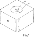
図1は、金属加工部品の切削加工のために用いられるスローアウェイチップの形の切削インサート若しくは切削板10を示している。この切削板10は、中央に円形の緊締窪み11を有しており、さらにこの緊締窪み11の中央には、球状若しくは円形の隆起部12が配置されている。前記緊締窪み11と隆起部12とは、適宜な支持工具に設けられた、この場合、板座と呼ばれる適当な収容部に切削板を固定するために役立つ。
FIG. 1 shows a cutting insert or
図2は、支持工具13に緊締された状態の前記切削板10の立体図を示している。この場合、押圧部材14に特に注目すべきである。この押圧部材14の下側は、切削板の上に述べた緊締窪み11に対する対応形状を有している(図3も参照のこと)。緊締ねじ17の締め付けにより生じる緊締力は、緊締爪16を介して切削板10に伝達される。特徴として、切削板の上部に位置する、この緊締爪の下側は球状の隆起部18を有しており、この隆起部18は、押圧部材14内に設けられた球状の凹部19内に突入し、遊びを有するねじ15によって固定されている。
Figure 2 shows a perspective view of the
図4は、板座の横断面図を示している。この横断面図では、複数の緊締エレメントの相互作用を説明したい。緊締ねじ17の締め付け時に、緊締爪16は下方へ運動し、斜面20によって、支持工具に設けられた類似の斜面に沿って同時に後方へ滑る。斜面とは反対の側で、緊締爪16の球状の隆起部18が、生ぜしめられた緊締力によって押圧部材14の球状の凹部19に形状接続的に結合され、かつ押圧部材14の隆起部21が、さらに形状接続的に切削板10の窪み11に係合しているので、横方向に板座角隅に向けられた運動は、個々の緊締エレメントによって切削板に伝達される(図10も参照のこと)。緊締力限界22への到達時には、緊締爪のてこ運動が増大する。押圧部材14は、さらにより大きい押圧力を切削板に行使し、この押圧部材14の載置面23によって切削板の表面をさらに付加的に押圧する。この相互作用の優れた特徴は、全てのエレメントの組合せによって、切削板が板座から外側へ外れてしまうことが、存在する形状と斜面とによりもはや不可能となることである。
FIG. 4 shows a cross-sectional view of the plate seat. In this cross-sectional view, the interaction of a plurality of tightening elements is to be explained. During tightening of the tightening
図5は、再び緊締爪−押圧部材−切削板の相互作用部の拡大図を示している。 FIG. 5 again shows an enlarged view of the interaction portion of the tightening claw-pressing member-cutting plate.
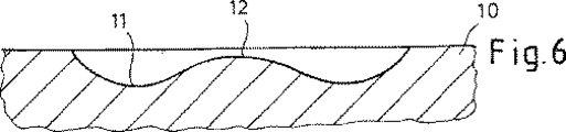
図6は、切削板の円形の窪み11の横断面図を示している。この窪み11の中央には、円形若しくは球状の隆起部12が設けられている。この場合、この隆起部12は、球の形状を有しており、窪み底部の上方かつ切削板表面の下方に位置していることを特徴とする。この窪み輪郭の横断面は円形であり、いわば球の垂直方向軸線を中心として延びており、これは、アメリカのドーナツの焼型を思い起こさせる。
FIG. 6 shows a cross-sectional view of the
図7は、押圧部材14の上側を示している。この押圧部材14の上側は、特徴として前記球欠19若しくは球状の窪み又は凹部を有している。
FIG. 7 shows the upper side of the
図8には、押圧部材14の下側が示されている。この押圧部材14の下側は、特徴としてドーナツ形の隆起部21を有しており、このドーナツ形の隆起部21は、切削板に設けられた緊締窪みの対応形状である。付加的な特徴は、ドーナツ中央へ向かって角度が上昇している接触面23と、切削板の溝縁部を面状接触ひいては損傷及び不十分な座着から保護する露出部25とである(図10も参照のこと)。
FIG. 8 shows the lower side of the
押圧部材14の別の特徴は、耐摩耗性の材料、例えば硬質合金、HSS又はセラミックによる性質と、切削加工時に形成される切削屑から緊締爪を保護するための外側輪郭の突出部24(図7参照)とである。球/球欠結合は、緊締エレメントと切削板との間の誤差補償及び位置補償のためにも役立つ。
Another feature of the
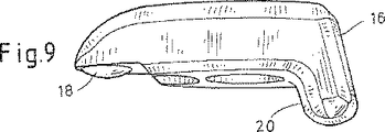
図9は、上に述べた球状の隆起部18を備えた緊締爪の下側を示している。この球の特徴は、とりわけこの球の直径が押圧部材14に設けられた球欠の直径よりも幾分大きく形成されており、これにより、力伝達が、球欠底部及び球先端における点状の負荷を介してではなく、球/球欠外側縁部26を介して可能となることである(図10参照)。別の特徴は緊締爪に設けられた斜面20である。この斜面20は、支持工具に設けられた斜面を介して案内される(図4及び図9参照)。これらの斜面は、緊締ねじの締め付け時に緊締エレメントの側部の運動が得られ、この運動が、切削板を板座の角隅に引き寄せるという効果をもたらす。この緊締爪は、比較的小さい寸法を備えた支持工具に用いるためのものである。
FIG. 9 shows the underside of the clamping claw with the
図11は、上に述べた球状の隆起部18を備えた緊締爪16の別の実施態様の下側を示している。この緊締爪16は、このより大きいエレメントの組み込みを可能にする寸法の所定の構成形式の支持工具に用いるためのものである。この緊締爪の特徴は、後方の範囲に図9とは異なる形に成形された斜面26である。この斜面26は図12に示したように、スリット27によって分離されて、10〜45°までの角度下に延びている。これら両方の斜面26の本発明による特徴は、これらの斜面26の円筒状の表面28である。これらの円筒状の表面28は、緊締ねじの締め付け時に緊締爪の側部の運動に対して付加的に、セルフセンタリングが、対応する支持工具13に専らこのセルフセンタリングのために形成された切欠き29内で得られるという効果を有する(図13を参照のこと)。
FIG. 11 shows the underside of another embodiment of a clamping
さらに図13に示した支持工具13に設けられた切欠き29の特徴は、平行に延びる2つの斜面30の円筒状の表面である。この円筒状の表面の半径は、緊締爪の円筒状の表面28よりも幾らか大きく設計されている。このことにより、これらの斜面の間のほぼ線状の接触と、互いに接触する円筒周面28及び30のセルフセンタリングによる斜面に沿った滑動とが可能となる。図14は、緊締爪と支持工具との間のこのような相互作用部を示す横断面図である。
Further, the feature of the
Claims (13)
Applications Claiming Priority (3)
| Application Number | Priority Date | Filing Date | Title |
|---|---|---|---|
| DE10136635 | 2001-07-26 | ||
| DE10208266A DE10208266A1 (en) | 2001-07-26 | 2002-02-26 | Stock-removing cutting tool has circular clamping trough with centre protrusion on cutting plate associated with matching circular ring on cam of pressure member which engages round protrusion |
| PCT/DE2002/002665 WO2003013770A1 (en) | 2001-07-26 | 2002-07-19 | Metal cutting tool and cutting plate provided in the shape of a donut |
Related Child Applications (1)
| Application Number | Title | Priority Date | Filing Date |
|---|---|---|---|
| JP2009032474A Division JP4873664B2 (en) | 2001-07-26 | 2009-02-16 | Cutting plate |
Publications (3)
| Publication Number | Publication Date |
|---|---|
| JP2004536719A JP2004536719A (en) | 2004-12-09 |
| JP2004536719A5 JP2004536719A5 (en) | 2008-10-16 |
| JP4308651B2 true JP4308651B2 (en) | 2009-08-05 |
Family
ID=26009790
Family Applications (1)
| Application Number | Title | Priority Date | Filing Date |
|---|---|---|---|
| JP2003518761A Expired - Fee Related JP4308651B2 (en) | 2001-07-26 | 2002-07-19 | Cutting tool and donut-shaped cutting plate |
Country Status (17)
| Country | Link |
|---|---|
| US (4) | US20040256608A1 (en) |
| EP (2) | EP1829635B1 (en) |
| JP (1) | JP4308651B2 (en) |
| KR (1) | KR100932814B1 (en) |
| CN (1) | CN100479956C (en) |
| AT (2) | ATE424953T1 (en) |
| BR (2) | BR0211463B1 (en) |
| CA (1) | CA2454964C (en) |
| DE (3) | DE10208266A1 (en) |
| DK (1) | DK1829635T3 (en) |
| ES (1) | ES2324558T3 (en) |
| IL (3) | IL160008A0 (en) |
| MX (1) | MXPA04000690A (en) |
| PL (1) | PL207195B1 (en) |
| PT (1) | PT1829635E (en) |
| RO (1) | RO123526B1 (en) |
| WO (1) | WO2003013770A1 (en) |
Families Citing this family (39)
| Publication number | Priority date | Publication date | Assignee | Title |
|---|---|---|---|---|
| DE10208266A1 (en) | 2001-07-26 | 2003-02-13 | Ceram Tec Ag Innovative Cerami | Stock-removing cutting tool has circular clamping trough with centre protrusion on cutting plate associated with matching circular ring on cam of pressure member which engages round protrusion |
| US7073986B2 (en) | 2001-11-08 | 2006-07-11 | Kennametal Inc. | Dimpled insert with retaining clamp |
| DE10239451A1 (en) * | 2002-08-28 | 2004-03-11 | Ceramtec Ag Innovative Ceramic Engineering | Cutting plate for mounting in a cutting tool for cutting cast material, especially cast iron, comprises a cutting plate upper side, a cutting edge |
| KR20060115855A (en) * | 2003-08-22 | 2006-11-10 | 세람텍 아게 이노바티베 세라믹 엔지니어링 | Die consisting of pcbn or a cbn composite material comprising a clamping depression |
| SE529312C2 (en) * | 2006-02-15 | 2007-07-03 | Seco Tools Ab | Cutting and cutting tools where the insert mounting holes have two contact points against a clamping device |
| US8454274B2 (en) * | 2007-01-18 | 2013-06-04 | Kennametal Inc. | Cutting inserts |
| US7883299B2 (en) * | 2007-01-18 | 2011-02-08 | Kennametal Inc. | Metal cutting system for effective coolant delivery |
| US9101985B2 (en) * | 2007-01-18 | 2015-08-11 | Kennametal Inc. | Cutting insert assembly and components thereof |
| US20100158621A1 (en) * | 2007-04-20 | 2010-06-24 | Wolfgang Zitzlaff | Cutting tool for recessing and grooving, comprising a replaceable abutment for the cutting element |
| DE102008001857A1 (en) | 2007-05-22 | 2008-11-27 | Ceramtec Ag | Plate seat with inserts |
| WO2008142096A1 (en) * | 2007-05-24 | 2008-11-27 | Ceramtec Ag | Cutting insert comprising a stabilising double-sided facet |
| WO2008155331A1 (en) | 2007-06-21 | 2008-12-24 | Ceramtec Ag | Negative insert having double-positive clearance surface |
| DE102008042493A1 (en) | 2007-10-02 | 2009-04-09 | Ceramtec Ag | Hard material insert and its mechanical clamping |
| DE102009027153A1 (en) | 2008-06-25 | 2009-12-31 | Ceramtec Ag | Supporting tool for hollow shaft taper tool in e.g. turning application during machining of metallic workpiece, has cutting body staying in direct contact with inner insert seat walls and bottom surface and indirectly contacting tool |
| WO2010104227A1 (en) * | 2009-03-13 | 2010-09-16 | Taegutec Ltd. | Tool holder clamp assembly for cutting inserts and its pressing plate |
| KR101018362B1 (en) | 2009-03-13 | 2011-03-04 | 대구텍 유한회사 | Tool holder clamp assembly for cutting inserts and its pressing plate |
| AT11469U1 (en) | 2009-04-10 | 2010-11-15 | Ceratizit Austria Gmbh | CUTTING TOOL |
| BRPI1016157A2 (en) * | 2009-04-21 | 2016-04-19 | Ceramtec Gmbh | screw joints in chip removal tools |
| CN102740999A (en) * | 2009-08-21 | 2012-10-17 | 陶瓷技术有限责任公司 | Precision pressing and sintering of cutting inserts, particularly indexable cutting inserts |
| DE102009042238A1 (en) * | 2009-09-18 | 2011-04-07 | Robert Bosch Gmbh | Clamping component with a cutting edge for producing an electrically conductive connection |
| KR101075292B1 (en) | 2010-01-14 | 2011-10-20 | 대구텍 유한회사 | Cutting tool |
| CN101774033B (en) * | 2010-01-19 | 2012-10-24 | 株洲钻石切削刀具股份有限公司 | Fastening structure for blade assembly |
| CN101879613B (en) * | 2010-06-09 | 2015-12-16 | 孙生强 | A kind of complex function indexable tool |
| JP5826271B2 (en) * | 2010-08-04 | 2015-12-02 | セラムテック ゲゼルシャフト ミット ベシュレンクテル ハフツングCeramTec GmbH | Cutting tool and cutting plate |
| US8827599B2 (en) | 2010-09-02 | 2014-09-09 | Kennametal Inc. | Cutting insert assembly and components thereof |
| EP2646186B1 (en) | 2010-12-01 | 2015-10-07 | CeramTec GmbH | Finish-pressed / final-sintered blanking die and method for producing same |
| IL211444A0 (en) * | 2011-02-27 | 2011-06-30 | Kennametal Inc | High feed cutting insert |
| ES2817782T3 (en) * | 2011-10-06 | 2021-04-08 | Ceram Gmbh | Miniature cutting insert |
| US8727674B2 (en) * | 2012-02-16 | 2014-05-20 | Kennametal Inc. | Tool holder with nubs for clamping a cutting insert with notches |
| US9120239B2 (en) * | 2013-02-21 | 2015-09-01 | Iscar, Ltd. | Cutting tool and cutting insert having insert key recesses for extracting and mounting therein |
| US9511421B2 (en) | 2013-06-14 | 2016-12-06 | Kennametal Inc. | Cutting tool assembly having clamp assembly comprising a clamp and a coolant plate |
| CN103465163A (en) * | 2013-09-16 | 2013-12-25 | 河南富耐克超硬材料股份有限公司 | Fixture for grinding tool |
| US20160016233A1 (en) * | 2014-07-17 | 2016-01-21 | Kennametal India Limited | Notched cutting inserts and applications thereof |
| CN104191047A (en) * | 2014-09-17 | 2014-12-10 | 江西志豪机械有限公司 | Split hobbing cutter |
| EP3227040A1 (en) | 2014-12-05 | 2017-10-11 | CeramTec GmbH | Cutting insert geometry |
| EP3242764B1 (en) * | 2015-01-09 | 2021-12-29 | CeramTec GmbH | Carrier tool |
| PT3512657T (en) * | 2017-03-22 | 2020-07-23 | Ceram Gmbh | Tool system |
| WO2018172462A1 (en) | 2017-03-24 | 2018-09-27 | Ceramtec Gmbh | Star-type indexable cutting insert and tool system |
| PT3575022T (en) * | 2018-05-29 | 2020-06-23 | Ceram Gmbh | Tool system |
Family Cites Families (38)
| Publication number | Priority date | Publication date | Assignee | Title |
|---|---|---|---|---|
| US2031334A (en) * | 1934-09-12 | 1936-02-18 | Apex Tool & Cutter Company Inc | Offset side supported tool holder |
| DE1602817A1 (en) * | 1967-09-20 | 1970-05-06 | Hans Heinlein | Insert arrangement |
| US3731356A (en) * | 1971-06-18 | 1973-05-08 | Gen Electric | Cutting tool |
| GB1567005A (en) | 1975-11-11 | 1980-05-08 | Girling Ltd | Disc brakes for vehicles |
| GB1567004A (en) * | 1976-10-20 | 1980-05-08 | Herbert Ltd A | Tool tip |
| US4277207A (en) * | 1977-10-05 | 1981-07-07 | J.P. Tool Ltd. | Helical broaching tool for curved surfaces |
| US4321846A (en) * | 1980-04-18 | 1982-03-30 | The Gillette Company | Tool holder |
| US4552491A (en) * | 1980-06-23 | 1985-11-12 | United Technologies Corporation | Cutting tool having cylindrical ceramic insert |
| US4395168A (en) * | 1980-12-19 | 1983-07-26 | Frank Vicari | Multiple cutter rotary tool |
| DE3136502A1 (en) * | 1981-09-15 | 1983-03-31 | Feldmühle AG, 4000 Düsseldorf | CUTTING TOOL |
| DE3136549A1 (en) * | 1981-09-15 | 1983-03-31 | Feldmühle AG, 4000 Düsseldorf | CUTTING TOOL |
| US4600341A (en) * | 1984-02-21 | 1986-07-15 | Board Harry B | Pocket reducing insert for toolholder and the like |
| US4697963A (en) * | 1985-02-08 | 1987-10-06 | Ingersoll Cutting Tool Company | Insert clamping device and insert therefor |
| US5053671A (en) * | 1987-11-16 | 1991-10-01 | Nissan Motor Company, Limited | Piezoelectric sensor for monitoring kinetic momentum |
| DE3823907A1 (en) * | 1988-07-14 | 1990-01-18 | Feldmuehle Ag | CLAMP HOLDER FOR CUTTING INSERTS |
| US4938639A (en) * | 1989-05-12 | 1990-07-03 | Kennametal Inc. | Combination tool holder |
| JP2701514B2 (en) | 1989-06-15 | 1998-01-21 | 三菱マテリアル株式会社 | Slow way tip clamping mechanism |
| NL8902275A (en) * | 1989-09-12 | 1991-04-02 | Duracarb Bv | CHISEL HOLDER AND CHISEL OF A CUTTING MACHINE. |
| JP2530762Y2 (en) * | 1991-03-15 | 1997-03-26 | 三菱マテリアル株式会社 | Indexable tip |
| US5207748A (en) * | 1991-11-12 | 1993-05-04 | Valenite Inc. | High productivity insert |
| US5477754A (en) * | 1993-08-30 | 1995-12-26 | Carboloy Inc. | Metal cutting inserts and method of making |
| US5733073A (en) * | 1994-03-31 | 1998-03-31 | Kennametal Inc. | Cutting tool assembly and cutting tool bit |
| DE4415425A1 (en) * | 1994-05-03 | 1995-11-09 | Krupp Widia Gmbh | Cutting tool |
| DE4430171C2 (en) * | 1994-08-25 | 1996-08-14 | Walter Ag | Form-locked insert |
| SE506679C2 (en) | 1995-06-21 | 1998-01-26 | Seco Tools Ab | Cutting tools, preferably for milling |
| DE19524945A1 (en) * | 1995-07-08 | 1997-01-09 | Cerasiv Gmbh | Cutting cutting tool |
| SE511759C2 (en) * | 1996-12-09 | 1999-11-22 | Sandvik Ab | Cutter holder for inserts |
| DE19720022A1 (en) * | 1997-05-13 | 1998-11-26 | Komet Stahlhalter Werkzeug | Cutting insert for machining |
| IL124496A (en) * | 1998-05-14 | 2003-05-29 | Iscar Ltd | Tool holder |
| SE513952C2 (en) * | 1998-05-29 | 2000-12-04 | Seco Tools Ab | Tools for cutting machining |
| US6217264B1 (en) * | 1998-05-30 | 2001-04-17 | Korloy, Inc. | Cutting insert having an improved chip breaker |
| JP2000117512A (en) | 1998-10-12 | 2000-04-25 | Dijet Ind Co Ltd | Throw-away tip |
| DE19854873A1 (en) | 1998-11-27 | 2000-05-31 | Widia Gmbh | Cutter for tool used for cutting ceramics has cutter held in place by hooked clamp |
| WO2000064615A1 (en) * | 1999-04-26 | 2000-11-02 | Sandvik Aktiebolag | A tool holder and a clamp plate for holding a cutting insert |
| DE10208266A1 (en) | 2001-07-26 | 2003-02-13 | Ceram Tec Ag Innovative Cerami | Stock-removing cutting tool has circular clamping trough with centre protrusion on cutting plate associated with matching circular ring on cam of pressure member which engages round protrusion |
| US7073986B2 (en) * | 2001-11-08 | 2006-07-11 | Kennametal Inc. | Dimpled insert with retaining clamp |
| JP5826271B2 (en) * | 2010-08-04 | 2015-12-02 | セラムテック ゲゼルシャフト ミット ベシュレンクテル ハフツングCeramTec GmbH | Cutting tool and cutting plate |
| CN102082669A (en) | 2010-12-23 | 2011-06-01 | 深圳市文鼎创数据科技有限公司 | Security certification method and device |
-
2002
- 2002-02-26 DE DE10208266A patent/DE10208266A1/en not_active Withdrawn
- 2002-07-19 IL IL16000802A patent/IL160008A0/en unknown
- 2002-07-19 EP EP07010335A patent/EP1829635B1/en not_active Expired - Lifetime
- 2002-07-19 BR BRPI0211463-1A patent/BR0211463B1/en not_active IP Right Cessation
- 2002-07-19 JP JP2003518761A patent/JP4308651B2/en not_active Expired - Fee Related
- 2002-07-19 DE DE50212156T patent/DE50212156D1/en not_active Expired - Lifetime
- 2002-07-19 DK DK07010335T patent/DK1829635T3/en active
- 2002-07-19 CN CNB028147596A patent/CN100479956C/en not_active Expired - Fee Related
- 2002-07-19 WO PCT/DE2002/002665 patent/WO2003013770A1/en active Application Filing
- 2002-07-19 KR KR1020047001120A patent/KR100932814B1/en not_active IP Right Cessation
- 2002-07-19 PL PL369428A patent/PL207195B1/en unknown
- 2002-07-19 ES ES07010335T patent/ES2324558T3/en not_active Expired - Lifetime
- 2002-07-19 EP EP02764523A patent/EP1414607B1/en not_active Expired - Lifetime
- 2002-07-19 DE DE10297850A patent/DE10297850A5/en not_active Withdrawn
- 2002-07-19 AT AT07010335T patent/ATE424953T1/en active
- 2002-07-19 CA CA2454964A patent/CA2454964C/en not_active Expired - Fee Related
- 2002-07-19 US US10/483,886 patent/US20040256608A1/en not_active Abandoned
- 2002-07-19 RO ROA200400053A patent/RO123526B1/en unknown
- 2002-07-19 AT AT02764523T patent/ATE392969T1/en active
- 2002-07-19 BR BRPI0216093-5A patent/BR0216093B1/en not_active IP Right Cessation
- 2002-07-19 PT PT07010335T patent/PT1829635E/en unknown
-
2004
- 2004-01-22 IL IL160008A patent/IL160008A/en not_active IP Right Cessation
- 2004-01-22 MX MXPA04000690A patent/MXPA04000690A/en active IP Right Grant
-
2006
- 2006-09-28 US US11/528,788 patent/US8388273B2/en not_active Expired - Lifetime
-
2009
- 2009-02-09 IL IL196978A patent/IL196978A/en not_active IP Right Cessation
-
2012
- 2012-03-22 US US13/427,325 patent/US9744598B2/en not_active Expired - Lifetime
-
2013
- 2013-12-04 US US14/096,649 patent/US9227248B2/en not_active Expired - Fee Related
Also Published As
Similar Documents
| Publication | Publication Date | Title |
|---|---|---|
| JP4308651B2 (en) | Cutting tool and donut-shaped cutting plate | |
| JP2004536719A5 (en) | ||
| JP4873664B2 (en) | Cutting plate | |
| JP2846020B2 (en) | Clamp holder for circular chip plate | |
| JP2008527251A (en) | Clamp for connecting the mounting member to the base | |
| US6135244A (en) | Plate device for supporting at least one brake pad for a vehicle disc brake | |
| JP2009039833A (en) | Clamp holder | |
| US20020121447A1 (en) | Device for holding disk-shaped storage elements | |
| JPH037403U (en) | ||
| JP2507853Y2 (en) | Cutting tool with circular slot insert | |
| SU1763096A1 (en) | Cutting tool | |
| JP2703511B2 (en) | Mirror holder | |
| CN215959085U (en) | Seat and combined seat board thereof | |
| JPH10244419A (en) | Throwaway type reamer | |
| JPS6128111Y2 (en) | ||
| SU1502210A1 (en) | Cutting tool | |
| JPH1061696A (en) | Disc brake for vehicle | |
| JP2009522127A (en) | Cutting tool fixed in shape connection on support plate | |
| SU1583220A1 (en) | Cutting tool | |
| JPH08240213A (en) | Synthetic resin moldings mounting structure | |
| JP2865415B2 (en) | Steering wheel | |
| FI83116B (en) | Connecting hook for building element made of stone | |
| SU1373480A1 (en) | Cutting tool | |
| JP2525959Y2 (en) | Cutting tools | |
| SU1135561A2 (en) | Cutting tool |
Legal Events
| Date | Code | Title | Description |
|---|---|---|---|
| A621 | Written request for application examination |
Free format text: JAPANESE INTERMEDIATE CODE: A621 Effective date: 20050719 |
|
| A131 | Notification of reasons for refusal |
Free format text: JAPANESE INTERMEDIATE CODE: A131 Effective date: 20080222 |
|
| A601 | Written request for extension of time |
Free format text: JAPANESE INTERMEDIATE CODE: A601 Effective date: 20080522 |
|
| A602 | Written permission of extension of time |
Free format text: JAPANESE INTERMEDIATE CODE: A602 Effective date: 20080529 |
|
| A601 | Written request for extension of time |
Free format text: JAPANESE INTERMEDIATE CODE: A601 Effective date: 20080623 |
|
| A602 | Written permission of extension of time |
Free format text: JAPANESE INTERMEDIATE CODE: A602 Effective date: 20080630 |
|
| A601 | Written request for extension of time |
Free format text: JAPANESE INTERMEDIATE CODE: A601 Effective date: 20080722 |
|
| A602 | Written permission of extension of time |
Free format text: JAPANESE INTERMEDIATE CODE: A602 Effective date: 20080731 |
|
| A524 | Written submission of copy of amendment under article 19 pct |
Free format text: JAPANESE INTERMEDIATE CODE: A524 Effective date: 20080821 |
|
| A131 | Notification of reasons for refusal |
Free format text: JAPANESE INTERMEDIATE CODE: A131 Effective date: 20081114 |
|
| A521 | Request for written amendment filed |
Free format text: JAPANESE INTERMEDIATE CODE: A523 Effective date: 20090216 |
|
| TRDD | Decision of grant or rejection written | ||
| A01 | Written decision to grant a patent or to grant a registration (utility model) |
Free format text: JAPANESE INTERMEDIATE CODE: A01 Effective date: 20090416 |
|
| A01 | Written decision to grant a patent or to grant a registration (utility model) |
Free format text: JAPANESE INTERMEDIATE CODE: A01 |
|
| A61 | First payment of annual fees (during grant procedure) |
Free format text: JAPANESE INTERMEDIATE CODE: A61 Effective date: 20090501 |
|
| R150 | Certificate of patent or registration of utility model |
Free format text: JAPANESE INTERMEDIATE CODE: R150 |
|
| FPAY | Renewal fee payment (event date is renewal date of database) |
Free format text: PAYMENT UNTIL: 20120515 Year of fee payment: 3 |
|
| FPAY | Renewal fee payment (event date is renewal date of database) |
Free format text: PAYMENT UNTIL: 20130515 Year of fee payment: 4 |
|
| R250 | Receipt of annual fees |
Free format text: JAPANESE INTERMEDIATE CODE: R250 |
|
| R250 | Receipt of annual fees |
Free format text: JAPANESE INTERMEDIATE CODE: R250 |
|
| R250 | Receipt of annual fees |
Free format text: JAPANESE INTERMEDIATE CODE: R250 |
|
| R250 | Receipt of annual fees |
Free format text: JAPANESE INTERMEDIATE CODE: R250 |
|
| LAPS | Cancellation because of no payment of annual fees |