JP4302829B2 - Liquid spraying device - Google Patents
Liquid spraying device Download PDFInfo
- Publication number
- JP4302829B2 JP4302829B2 JP21808699A JP21808699A JP4302829B2 JP 4302829 B2 JP4302829 B2 JP 4302829B2 JP 21808699 A JP21808699 A JP 21808699A JP 21808699 A JP21808699 A JP 21808699A JP 4302829 B2 JP4302829 B2 JP 4302829B2
- Authority
- JP
- Japan
- Prior art keywords
- rail
- traveling
- hose
- carriage
- hose support
- Prior art date
- Legal status (The legal status is an assumption and is not a legal conclusion. Google has not performed a legal analysis and makes no representation as to the accuracy of the status listed.)
- Expired - Fee Related
Links
Images


Classifications
-
- Y—GENERAL TAGGING OF NEW TECHNOLOGICAL DEVELOPMENTS; GENERAL TAGGING OF CROSS-SECTIONAL TECHNOLOGIES SPANNING OVER SEVERAL SECTIONS OF THE IPC; TECHNICAL SUBJECTS COVERED BY FORMER USPC CROSS-REFERENCE ART COLLECTIONS [XRACs] AND DIGESTS
- Y02—TECHNOLOGIES OR APPLICATIONS FOR MITIGATION OR ADAPTATION AGAINST CLIMATE CHANGE
- Y02A—TECHNOLOGIES FOR ADAPTATION TO CLIMATE CHANGE
- Y02A40/00—Adaptation technologies in agriculture, forestry, livestock or agroalimentary production
- Y02A40/10—Adaptation technologies in agriculture, forestry, livestock or agroalimentary production in agriculture
- Y02A40/25—Greenhouse technology, e.g. cooling systems therefor
Landscapes
- Greenhouses (AREA)
- Details Or Accessories Of Spraying Plant Or Apparatus (AREA)
- Spray Control Apparatus (AREA)
Description
【0001】
【発明の属する技術分野】
本発明は、栽培植物の上方、特に、温室内の上方に配設して、散水、防除、消毒等を行うための液体散布装置に関する。
【0002】
【従来の技術】
この種の液体散布装置としては、例えば、図5に示したような装置が知られている。すなわち、温室内に所定の高さで温室の長手方向に沿って走行レール101を設置し、この走行レール101に散布体支持用台車102を走行させ、該散布体支持用台車102に送液管103aと複数の散布ノズル103bを備えた散布体103を支持させた構成である。そして、この散布体支持用台車102が走行することにより、散布体103が走行レール101に沿って移動するため、温室内の所望の位置に水、液肥等の液体を散布することができる。
【0003】
上記した装置においては、散布体103を構成する送液管103aに水や液肥等の液体を供給する手段として、散布体支持用台車102に支持されている送液管103aの端部に、他端が図示しない給液源に接続され、散布体103が走行レール101に沿って給液源から最も離れた位置まで移動しても該散布体支持用台車102まで十分届くだけの長さを有する柔軟な給液ホース110を接続し、該給液ホース110を経由して送液する手段を採用している。また、給液ホース110が、このように温室の長手方向の長さ以上の長さを有しているため、散布体支持用台車102が給液源に接近するほど、給液ホース110の中途部分が余って下方に垂れ下がり、栽培植物に損傷を与えたり、作業の邪魔になったり、あるいは、中途で屈曲して液体の送液が円滑に行われなくなったりするため、該給液ホース110を螺旋状となるように巻き、それによって形成される各螺旋リング部の頂部付近のそれぞれをホース支持用台車111で支持している。
【0004】
より具体的には、このホース支持用台車111は、走行レール102上を走行する車輪111aと、下端部が走行レール102の下方に位置するように設けられる支持金具111bと、該支持金具111bの下端に取り付けられた吊り下げ部材(図示せず)とから構成されており、給液ホース110を螺旋状に巻きながら各吊り下げ部材に支持させている。従って、散布体支持用台車102が給液源から離間する方向へ移動する際には、給液ホース110が追随して引っ張られて伸びていくと共に、これに伴い、該ホース支持用台車111が走行レール101に沿って同方向に移動していく。散布体支持用台車102が逆方向へ移動する際には、ホース支持用台車111が散布体支持用台車102に押されて同方向へ移動し、これに伴い、給液ホース110が螺旋状に巻かれていき、走行レール101のうち、給液源側の端部付近に給液ホース110の螺旋状に巻かれた部分とホース支持用台車111が、隣接するもの同士接近して収容される。
【0005】
【発明が解決しようとする課題】
しかしながら、上記した装置では、散布体支持用台車102が、走行レール101の一方の端部方向に移動した場合には、給液ホース110が螺旋状に巻かれて縮んで行くが、当然に、隣接するホース支持用台車111が接触し合う段階までしか縮むことはできない。従って、隣接するホース支持用台車111が接触し合った状態における一方の端のホース支持用台車111から他方の端のホース支持用台車111までは、散布体103から給液することができないデッドスペースとなる。このデッドスペースは小さいほど望ましく、そのための手段としてホース支持用台車111をより小さな車体及び車輪から構成することが考えられる。しかしながら、この場合には、ホース支持用台車111の走行が不安定となり、走行レール101を走行中に、ガタついたり、傾いたりし易く、安定性に欠けるという問題がある。特に、上記のようにホース110が螺旋状に収容されるように巻いているため、該ホース110が伸張していっても完全な直線状になるのではなく、多少のゆがみや曲がりを有しており、ガタつきや傾きが生じ易い。
【0006】
本発明は、上記した点に鑑みなされたものであり、安定した走行が可能な大きさのホース支持用台車を採用しても、収納時においてホース支持用台車が接触して連なった際の長さを従来よりも短くでき、給液されないデッドスペースを小さくすることができる液体散布装置を提供することを課題とする。
【0007】
【課題を解決するための手段】
上記した課題を解決するため、請求項1記載の本発明の液体散布装置は、走行レールに沿って走行可能な散布体支持用台車と、該散布体支持用台車に支持された散布体と、該散布体に接続される給液ホースを支持するために、走行レールに沿って走行可能に複数配設されるホース支持用台車とを備えた液体散布装置であって、
前記走行レールに接続され、上下に複数段のレール部を有する収納用レールを備えると共に、一部の前記ホース支持用台車は、走行レール上を走行する走行車輪とは独立して回転し、前記収納用レールのレール部のみを走行する補助車輪を備えており、
補助車輪を有しないホース支持用台車と補助車輪を有するホース支持用台車とが前記走行レール上において隣同士となるように配置され、前記収納用レールにおいては、前記補助車輪を有しないホース支持用台車と補助車輪を有するホース支持用台車とが異なるレール部を走行して収納されるように設けられていることを特徴とする。
【0008】
請求項2記載の本発明の液体散布装置は、請求項1記載の液体散布装置であって、前記収納用レールのレール部が上下2段で設けられ、前記一部のホース支持用台車に設けられる補助車輪は、その走行車輪の上方に設けられ、前記収納用レールにおいて、補助車輪を有しないホース支持用台車の走行車輪が下段のレール部を走行し、補助車輪を有するホース支持用台車の該補助車輪が上段のレール部を走行して収納されるように設けられていることを特徴とする。
【0009】
請求項3記載の本発明の液体散布装置は、請求項1又は2記載の液体散布装置であって、前記各ホース支持用台車の走行車輪の走行方向前方部と後方部とに、バンパー部が設けられていることを特徴とする。
【0010】
【発明の実施の形態】
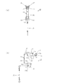
以下、図面に示した実施の形態に基づき本発明をさらに詳細に説明する。図1は、本発明の液体散布装置で用いられる第1のタイプのホース支持用台車10を示す図で、(a)は側面図、(b)は正面から見た分解図である。
【0011】
図1に示したように、第1のタイプのホース支持用台車10は、後述の第2のタイプのホース支持用台車20のように補助車輪を有しておらず、次のような構成を備えている。すなわち、筒状の走行車輪11と、周囲がこの走行車輪11の内周面11aに接するように、該走行車輪11の中空部内に配設され、該走行車輪11を円滑に回転させるためのベアリング12と、一端13aが該ベアリング12の中心孔12aに固定される固定軸13と、この固定軸13の他端13bに固定連結されるホース吊りフレーム14とを有して構成される。
【0012】
ホース吊りフレーム14は、所定の長さと幅を備えた金属板を折り曲げ成形したものであり、具体的には、図1(b)に示したように正面から見て、上下に2つの水平片14a,14bと、この水平片14a,14bの一端側において両者を接続している垂直片14cと、上側の水平片14aの他端側において下方に屈曲された軸固定用片14dと、下側の水平片14bの他端側から略180度屈曲された後、その端部がさらに下方に屈曲された吊り部材取り付け片14eとを有している。また、軸固定用片14dには固定軸13の他端13bが挿入固定される挿入孔14fが形成されている。軸固定用片14dは、走行車輪11の中空部内に挿入されるため、軸固定用片14dの幅及び上側の水平片14aからの屈曲長さは、該走行車輪11の中空部内に収まるような大きさで形成されている。また、吊り部材取り付け片14eには、厚み方向に貫通する係止孔14gが形成されており、この係止孔14gに給液ホース(図示せず)を吊り下げるためのチェーンや紐等の吊り部材15の上端部が係止される。
【0013】
本実施の形態のホース吊りフレーム14は、さらに、上側の水平片14aの幅方向両側縁であって、走行車輪11の中空部内に挿入されてない部位から、それぞれ走行車輪11の水平方向の幅よりも外側まで延びた後、上側に向かって屈曲され、さらに、該水平片14aの他端側に向かって該水平片14aと略平行となるように曲成された突出片16,17が設けられている。この突出片16,17が走行車輪11の走行方向前方部と後方部とに設けられるバンパー部となる。すなわち、図3に示したように、隣接するホース支持用台車10,20が接触した際には、互いに、走行車輪11,21同士は接触せずに、バンパー部となる突出片17と26、及び突出片16と27同士が接触することになる。従って、給液ホースが収納されていく際には、一方のホース支持用台車の突出片により、隣接する他方のホース支持用台車の突出片を押していくことになるため、走行車輪11,21の回転が損なわれず、安定した走行が可能となる。
【0014】
なお、このような安定した走行をより確実にするため、図1に示したように、下側の水平片14bにも、幅方向各側縁から一旦外側に突出した後、下方に屈曲させたバンパー部として機能する突出片18,19を設けておくことが好ましい。
【0015】
図2は、本発明の液体散布装置で用いられる第2のタイプのホース支持用台車20を示す図で、(a)は側面図、(b)は正面から見た分解図である。
【0016】
このホース支持用台車20は、筒状の走行車輪21と、周囲がこの走行車輪21の内周面21aに接するように、該走行車輪21の中空部内に配設され、該走行車輪21を円滑に回転させるためのベアリング22と、一端23aが該ベアリング22の中心孔22aに固定される固定軸23と、この固定軸23の他端23bに固定連結されるホース吊りフレーム24とを有している点は上記した第1のタイプのホース支持用台車10と同様である。また、ホース吊り用フレーム24の構成も同様で、図2(b)に示したように正面から見て、上下に2つの水平片24a,24b、垂直片24c、軸固定用片24d、吊り部材取り付け片24eを有し、軸固定用片24dには固定軸23の他端23bが挿入固定される挿入孔24fが形成され、吊り部材取り付け片24eには、厚み方向に貫通する係止孔24gが形成されており、この係止孔24gに給液ホース(図示せず)を吊り下げるためのチェーンや紐等の吊り部材25の上端部が係止されるようになっている。また、バンパー部として機能する突出片26,27,28,29も、上記の第1のタイプのホース支持用台車10と同様の位置に設けられている。
【0017】
但し、この第2のタイプのホース支持用台車20は、走行車輪11の上方に位置し、該走行車輪11とは独立して回転する補助車輪30を備えている点で第1のタイプのホース支持用台車10と異なる。
【0018】
補助車輪30は、ホース吊りフレーム24の垂直片24cに沿ってネジ31により固定される固定片32aと、該固定片32aの上端から略直角に折り曲げられた水平片32bと、この水平片32bの端部から略直角に立ち上げられた軸支持片32cとを備えた補助金具32を介して取り付けられる。より具体的には、この補助金具の軸支持片32cの中央部に回転軸33を挿通し、軸支持片32cを挟んだ回転軸33の両側に補助車輪30を構成する2つのローラ30a,30bが支持されている。なお、図2(a)に示したように、補助車輪30は、該補助車輪30が走行する後述の収納用レール50の構造が複雑にならないよう、その回転中心と走行車輪21の回転中心とが垂直方向に一直線上に位置するように設けられる。
【0019】
上記したホース支持用台車10,20は、図3に示した走行レール40において交互に配設される。すなわち、第1のタイプのホース支持用台車10を中心に見れば、その前後には第2のタイプのホース支持用台車20が走行し、逆に第2のタイプのホース支持用台車20を中心に見れば、その前後には第1のタイプのホース支持用台車10が走行するように配設される。そして、いずれも、該走行レール40の端部に接続された収納用レール50に収納されるものである。
【0020】
収納用レール50は、走行レール40との接続端51は、該走行レール40と断面の大きさがほぼ同じに形成されているが、接続端51から所定の長さまで、その底板52が下方に傾斜していく傾斜板部52aと、該傾斜板部52aの終端から水平になっている水平板部52bとを有している。この傾斜板部52aと水平板部52bとからなる底板52上が下段のレール部53となる。
【0021】
その一方、該収納用レール50の上部には、図4に示したように、該収納用レール50のフレーム54に対してネジ55によって、対向して取り付けられた2つのL字状部材56,57が配設されている。このL字状部材56,57は、走行レール40との接続端51から収納用レール50の全長に亘って設けられている。L字状部材56,57の底板部56a,57aは、ホース支持用台車10,20に設けられた走行車輪11,21及びバンパー部となる突出片16,17,26,27よりも上部に位置し、かつ第2のタイプのホース支持用台車20に設けられる補助車輪30が接触し得る高さで設けられており、このL字状部材56,57により上段のレール部58が構成されている。
【0022】
本実施の形態によれば、散布体支持用台車が走行レール40に沿って走行すると、給液ホースを介してホース支持用台車10,20は牽引され、あるいは散布体支持用台車によって押されることにより、走行レール40上を走行する(図5参照)。走行レール40上を走行している間は、ホース支持用台車10,20の動作は従来の装置と同様であるが、散布体支持用台車によって押されて、走行レール40の一方の端部に接続された収納用レール50に収納される際の動作が異なる。
【0023】
すなわち、本実施の形態では、図3に示したように、散布体支持用台車によって押されて収納される際には、まず、走行レール40の端部に近づいた段階で、該走行レール40上において隣接する第1のタイプのホース支持用台車10と第2のタイプのホース支持用台車20とが接近する。このとき、最接近したとしても、第1のタイプのホース支持用台車10の突出片16〜19と第2のタイプのホース支持用台車20の突出片26〜29とが接触するまでであるから、2つのホース支持用台車10,20の走行車輪11,21の中心間の間隔D1は、少なくとも該走行車輪11,21の直径分はある。
【0024】
しかしながら、走行レール40の端部を過ぎると、第2のタイプのホース支持用台車20は、その補助車輪30が上段のレール部58を構成するL字状部材57,58の底板部57a,58aに係合し、走行車輪21が浮いた状態で該底板部57a,58aに沿って収納用レール50内を走行するのに対し、第1のタイプのホース支持用台車10は、補助車輪を有しないため、走行車輪11がそのまま下段のレール部53を構成する傾斜板部52a及び水平板部52b上を走行する。従って、上段のレール部58には第2のタイプのホース支持用台車20のみが収容され、下段のレール部53には第1のタイプのホース支持用台車10のみが収容されることになる。
【0025】
このため、上段のレール部58では第2のタイプのホース支持用台車20同士が接触し合い、下段のレール部53では第1のタイプのホース支持用台車10同士が接触し合う。この結果、第2のタイプのホース支持用台車20の突出片26〜29と第1のタイプのホース支持用台車の突出片16〜19とは互い違いとなり、この状態における第2のタイプのホース支持用台車20の走行車輪21と第1のタイプのホース支持用台車10の走行車輪11との中心間の間隔D2は、走行車輪11,21の直径よりも小さくなる。これにより、収納用レール50の各レール部53,58における一方の端に配置されたホース支持用台車10又は20から他方の端に配置されたホース支持用台車10又は20までの収納状態の長さは、従来の半分以下になり、給液できないデッドスペースが大幅に減少する。
【0026】
なお、本発明はホース支持用台車10,20の収納に要する長さを小さくするために、収納用レール50に複数段のレール部を有し、ホース支持用台車10,20を各レール部に分配して収納できればよく、上記した実施の形態に限定されるものではないことはもちろんである。例えば、上記した説明では、上下2段のレール部53,58を設け、そのうち下段のレール部53に傾斜板部52aを設けているが、逆に上段のレール部58に上方に傾斜する傾斜板部を設ける構成としてもよい。また、両方のレール部53,58に傾斜板部を設ける構成とすることもできる。
【0027】
【発明の効果】
本発明の液体散布装置によれば、走行レールに接続され、上下に複数段のレール部を有する収納用レールを備えている。また、ホース支持用台車として、走行レール上を走行する走行車輪とは独立して回転し、前記収納用レールのレール部のみを走行する補助車輪を備えたものと、補助車輪を有しないホース支持用台車とを用いている。従って、補助車輪を有するホース支持用台車と補助車輪を有しないホース支持用台車とを、収納用レールにおいて異なるレール部に収納することができるため、収納状態におけるホース支持用台車の一方の端に配置されたものから他方の端に配置されたものまでの連なった際の長さが小さくなり、温室内のおいて給液できないデッドスペースが従来よりも小さくなる。また、このため、走行車輪として従来よりも直径の大きなものを使用しても、収納スペースが従来と比較して大きくならないため、ホース支持用台車のより安定した走行を実現することが可能となる。
【図面の簡単な説明】
【図1】図1は、本発明の一の実施の形態に係る液体散布装置に用いられる第1のタイプのホース支持用台車を示す図であり、(a)は側面図、(b)は正面から見た分解図である。
【図2】図2は、本発明の一の実施の形態に係る液体散布装置に用いられる第2のタイプのホース支持用台車を示す図であり、(a)は側面図、(b)は正面から見た分解図である。
【図3】図3は、本発明の一の実施の形態に係る液体散布装置に用いられる収納用レールの作用を説明するための側面図である。
【図4】図4(a)は、図3のA−A線に沿って見た第1のタイプのホース支持用台車を示す図であり、図4(b)は、図3のA−A線に沿って見た第2のタイプのホース支持用台車を示す図である。
【図5】従来の液体散布装置の一例を示す斜視図である。
【符号の説明】
10,20 ホース支持用台車
11,21 走行車輪
14,24 フレーム
16,17,18,19,26,27.28,29 突出片
30 補助車輪
40 走行レール
50 収納用レール
53 下段のレール部
58 上段のレール部[0001]
BACKGROUND OF THE INVENTION
The present invention relates to a liquid spraying device that is disposed above a cultivated plant, in particular, above a greenhouse to perform watering, control, disinfection, and the like.
[0002]
[Prior art]
As this type of liquid spraying device, for example, a device as shown in FIG. 5 is known. In other words, a traveling
[0003]
In the above-described apparatus, as means for supplying liquid such as water or liquid fertilizer to the
[0004]
More specifically, the
[0005]
[Problems to be solved by the invention]
However, in the above-described device, when the sprinkler support
[0006]
The present invention has been made in view of the above-described points, and even when a hose support cart having a size capable of stable running is employed, the length when the hose support carts come into contact with each other during storage is long. It is an object of the present invention to provide a liquid spraying device that can be made shorter than before and can reduce a dead space in which liquid is not supplied.
[0007]
[Means for Solving the Problems]
In order to solve the above-described problem, the liquid spraying device of the present invention according to
The storage rail is connected to the traveling rail, and includes a storage rail having a plurality of upper and lower rail portions, and some of the hose supporting carriages rotate independently of traveling wheels traveling on the traveling rail, It has auxiliary wheels that run only on the rail part of the storage rail,
A hose support carriage that does not have auxiliary wheels and a hose support carriage that has auxiliary wheels are arranged next to each other on the traveling rail, and the storage rail is for hose support that does not have the auxiliary wheels. The carriage and the hose supporting carriage having auxiliary wheels are provided so as to travel and be stored on different rail portions.
[0008]
A liquid spraying device according to a second aspect of the present invention is the liquid spraying device according to the first aspect, wherein the rail portion of the storage rail is provided in two upper and lower stages, and is provided on the part of the hose support cart. The auxiliary wheel is provided above the traveling wheel. In the storage rail, the traveling wheel of the hose supporting carriage that does not have the auxiliary wheel travels on the lower rail portion, and the hose supporting carriage having the auxiliary wheel is provided. The auxiliary wheels are provided so as to run and be accommodated on the upper rail portion.
[0009]
A liquid spraying device according to a third aspect of the present invention is the liquid spraying device according to the first or second aspect, wherein bumper portions are provided at a front portion and a rear portion in the traveling direction of the traveling wheel of each hose supporting carriage. It is provided.
[0010]
DETAILED DESCRIPTION OF THE INVENTION
Hereinafter, the present invention will be described in more detail based on the embodiments shown in the drawings. 1A and 1B are views showing a first type of
[0011]
As shown in FIG. 1, the first type hose support
[0012]
The
[0013]
The
[0014]
In order to make such a stable running more reliable, as shown in FIG. 1, the lower horizontal piece 14b is also protruded outward from each side edge in the width direction and then bent downward. It is preferable to provide protruding
[0015]
2A and 2B are views showing a second type of
[0016]
The
[0017]
However, the second type of
[0018]
The
[0019]
The above-described
[0020]
The
[0021]
On the other hand, on the upper portion of the
[0022]
According to the present embodiment, when the scatterer support carriage travels along the traveling
[0023]
That is, in the present embodiment, as shown in FIG. 3, when being pushed and stored by the scatterer supporting carriage, first, when the traveling
[0024]
However, when the end of the traveling
[0025]
Therefore, the second type
[0026]
In the present invention, in order to reduce the length required for storing the
[0027]
【The invention's effect】
According to the liquid spraying apparatus of the present invention, the storage rail is provided that is connected to the traveling rail and has a plurality of rail portions in the vertical direction. Further, as a hose support cart, a hose support that does not have an auxiliary wheel, and an auxiliary wheel that rotates independently of a traveling wheel that travels on a traveling rail and travels only on the rail portion of the storage rail. Used for trolleys. Accordingly, the hose support carriage having auxiliary wheels and the hose support carriage not having auxiliary wheels can be stored in different rail portions in the storage rail. The length from the arrangement to the arrangement at the other end is reduced, and the dead space that cannot be supplied in the greenhouse becomes smaller than before. For this reason, even if a wheel having a diameter larger than that of the conventional wheel is used as the traveling wheel, the storage space does not become larger than that of the conventional wheel, so that it is possible to realize more stable traveling of the hose support carriage. .
[Brief description of the drawings]
FIG. 1 is a view showing a first type of hose support carriage used in a liquid spraying apparatus according to an embodiment of the present invention, wherein (a) is a side view and (b) is a side view. It is the exploded view seen from the front.
FIGS. 2A and 2B are views showing a second type of hose support carriage used in the liquid spraying apparatus according to the embodiment of the present invention, wherein FIG. 2A is a side view, and FIG. It is the exploded view seen from the front.
FIG. 3 is a side view for explaining the operation of the storage rail used in the liquid spraying apparatus according to one embodiment of the present invention.
4 (a) is a view showing a first type of hose support carriage as seen along the line AA in FIG. 3, and FIG. 4 (b) is a view taken along line A-A in FIG. It is a figure which shows the 2nd type hose support trolley seen along the A line.
FIG. 5 is a perspective view showing an example of a conventional liquid spraying device.
[Explanation of symbols]
10, 20
Claims (3)
前記走行レールに接続され、上下に複数段のレール部を有する収納用レールを備えると共に、一部の前記ホース支持用台車は、走行レール上を走行する走行車輪とは独立して回転し、前記収納用レールのレール部のみを走行する補助車輪を備えており、
補助車輪を有しないホース支持用台車と補助車輪を有するホース支持用台車とが前記走行レール上において隣同士となるように配置され、前記収納用レールにおいては、前記補助車輪を有しないホース支持用台車と補助車輪を有するホース支持用台車とが異なるレール部を走行して収納されるように設けられていることを特徴とする液体散布装置。In order to support a scatterer supporting carriage that can travel along the traveling rail, a scatterer supported by the scatterer supporting carriage, and a liquid supply hose connected to the scatterer, along the traveling rail A liquid spraying device comprising a plurality of hose support carts arranged so as to be able to travel,
The storage rail is connected to the traveling rail, and includes a storage rail having a plurality of upper and lower rail portions, and some of the hose supporting carriages rotate independently of traveling wheels traveling on the traveling rail, It has auxiliary wheels that run only on the rail part of the storage rail,
A hose support carriage that does not have auxiliary wheels and a hose support carriage that has auxiliary wheels are arranged next to each other on the traveling rail, and the storage rail is for hose support that does not have the auxiliary wheels. A liquid spraying apparatus, wherein the carriage and the hose supporting carriage having auxiliary wheels are provided so as to travel and be stored on different rails.
Priority Applications (1)
| Application Number | Priority Date | Filing Date | Title |
|---|---|---|---|
| JP21808699A JP4302829B2 (en) | 1999-07-30 | 1999-07-30 | Liquid spraying device |
Applications Claiming Priority (1)
| Application Number | Priority Date | Filing Date | Title |
|---|---|---|---|
| JP21808699A JP4302829B2 (en) | 1999-07-30 | 1999-07-30 | Liquid spraying device |
Publications (2)
| Publication Number | Publication Date |
|---|---|
| JP2001038261A JP2001038261A (en) | 2001-02-13 |
| JP4302829B2 true JP4302829B2 (en) | 2009-07-29 |
Family
ID=16714429
Family Applications (1)
| Application Number | Title | Priority Date | Filing Date |
|---|---|---|---|
| JP21808699A Expired - Fee Related JP4302829B2 (en) | 1999-07-30 | 1999-07-30 | Liquid spraying device |
Country Status (1)
| Country | Link |
|---|---|
| JP (1) | JP4302829B2 (en) |
Families Citing this family (1)
| Publication number | Priority date | Publication date | Assignee | Title |
|---|---|---|---|---|
| CN102613035A (en) * | 2012-04-19 | 2012-08-01 | 苏州博田自动化技术有限公司 | Single-rail spraying machine |
-
1999
- 1999-07-30 JP JP21808699A patent/JP4302829B2/en not_active Expired - Fee Related
Also Published As
| Publication number | Publication date |
|---|---|
| JP2001038261A (en) | 2001-02-13 |
Similar Documents
| Publication | Publication Date | Title |
|---|---|---|
| US5462298A (en) | Water hose cart | |
| US5522677A (en) | Travelling concreting device | |
| US7216875B2 (en) | Shopping cart having caster lift | |
| KR101386924B1 (en) | Type Control Sprayers wagon | |
| JP4302829B2 (en) | Liquid spraying device | |
| DE1628638B2 (en) | MOBILE VACUUM CLEANER | |
| KR101254223B1 (en) | Watering vehicle for horse racing track | |
| CN105794602A (en) | Flower sprinkling equipment and operation method thereof | |
| US6216882B1 (en) | Retractable bicycle rack | |
| JPH1075703A (en) | Spray nozzle supporting structure for self-propelled sprayer | |
| JPH10108561A (en) | Self-traveling spraying device for greenhouse cultivation with improved housing and moving performance | |
| JP3929002B2 (en) | Hose support cart and liquid spraying apparatus using the hose support cart | |
| US7077458B2 (en) | Awning assembly and intermediate supports | |
| JPH1075701A (en) | Spray nozzle supporting structure for self-propelled sprayer | |
| US20080084035A1 (en) | Cart with caster lift | |
| JP5403265B2 (en) | Liquid spraying treatment equipment | |
| KR200223575Y1 (en) | Washing machine for vinyl house | |
| JPH0920175A (en) | Installing structure of getting on and off step | |
| JP3133038B1 (en) | Hose reel with moving mechanism | |
| CN223405171U (en) | Bed frame steel surface treatment device | |
| JP2681866B2 (en) | Bogie used for plumbing method | |
| JP3814024B2 (en) | Self-propelled sprayer nozzle hole support structure | |
| JPS6038310Y2 (en) | Structure of communication cabinet | |
| JPH0529989Y2 (en) | ||
| CN215992493U (en) | Gardens spraying equipment |
Legal Events
| Date | Code | Title | Description |
|---|---|---|---|
| A621 | Written request for application examination |
Free format text: JAPANESE INTERMEDIATE CODE: A621 Effective date: 20060616 |
|
| RD02 | Notification of acceptance of power of attorney |
Free format text: JAPANESE INTERMEDIATE CODE: A7422 Effective date: 20070306 |
|
| A977 | Report on retrieval |
Free format text: JAPANESE INTERMEDIATE CODE: A971007 Effective date: 20090401 |
|
| TRDD | Decision of grant or rejection written | ||
| A01 | Written decision to grant a patent or to grant a registration (utility model) |
Free format text: JAPANESE INTERMEDIATE CODE: A01 Effective date: 20090421 |
|
| A01 | Written decision to grant a patent or to grant a registration (utility model) |
Free format text: JAPANESE INTERMEDIATE CODE: A01 |
|
| A61 | First payment of annual fees (during grant procedure) |
Free format text: JAPANESE INTERMEDIATE CODE: A61 Effective date: 20090423 |
|
| FPAY | Renewal fee payment (event date is renewal date of database) |
Free format text: PAYMENT UNTIL: 20120501 Year of fee payment: 3 |
|
| R150 | Certificate of patent or registration of utility model |
Free format text: JAPANESE INTERMEDIATE CODE: R150 |
|
| FPAY | Renewal fee payment (event date is renewal date of database) |
Free format text: PAYMENT UNTIL: 20120501 Year of fee payment: 3 |
|
| FPAY | Renewal fee payment (event date is renewal date of database) |
Free format text: PAYMENT UNTIL: 20130501 Year of fee payment: 4 |
|
| FPAY | Renewal fee payment (event date is renewal date of database) |
Free format text: PAYMENT UNTIL: 20140501 Year of fee payment: 5 |
|
| LAPS | Cancellation because of no payment of annual fees |