JP4301890B2 - IMAGING DEVICE AND IMAGING DEVICE CONTROL METHOD - Google Patents
IMAGING DEVICE AND IMAGING DEVICE CONTROL METHOD Download PDFInfo
- Publication number
- JP4301890B2 JP4301890B2 JP2003279920A JP2003279920A JP4301890B2 JP 4301890 B2 JP4301890 B2 JP 4301890B2 JP 2003279920 A JP2003279920 A JP 2003279920A JP 2003279920 A JP2003279920 A JP 2003279920A JP 4301890 B2 JP4301890 B2 JP 4301890B2
- Authority
- JP
- Japan
- Prior art keywords
- output signal
- main
- sensitivity
- sub
- ratio
- Prior art date
- Legal status (The legal status is an assumption and is not a legal conclusion. Google has not performed a legal analysis and makes no representation as to the accuracy of the status listed.)
- Expired - Fee Related
Links
Images


Classifications
-
- H—ELECTRICITY
- H04—ELECTRIC COMMUNICATION TECHNIQUE
- H04N—PICTORIAL COMMUNICATION, e.g. TELEVISION
- H04N3/00—Scanning details of television systems; Combination thereof with generation of supply voltages
- H04N3/10—Scanning details of television systems; Combination thereof with generation of supply voltages by means not exclusively optical-mechanical
- H04N3/14—Scanning details of television systems; Combination thereof with generation of supply voltages by means not exclusively optical-mechanical by means of electrically scanned solid-state devices
- H04N3/15—Scanning details of television systems; Combination thereof with generation of supply voltages by means not exclusively optical-mechanical by means of electrically scanned solid-state devices for picture signal generation
- H04N3/155—Control of the image-sensor operation, e.g. image processing within the image-sensor
-
- H—ELECTRICITY
- H04—ELECTRIC COMMUNICATION TECHNIQUE
- H04N—PICTORIAL COMMUNICATION, e.g. TELEVISION
- H04N25/00—Circuitry of solid-state image sensors [SSIS]; Control thereof
- H04N25/50—Control of the SSIS exposure
- H04N25/57—Control of the dynamic range
- H04N25/58—Control of the dynamic range involving two or more exposures
- H04N25/581—Control of the dynamic range involving two or more exposures acquired simultaneously
- H04N25/585—Control of the dynamic range involving two or more exposures acquired simultaneously with pixels having different sensitivities within the sensor, e.g. fast or slow pixels or pixels having different sizes
Landscapes
- Engineering & Computer Science (AREA)
- Multimedia (AREA)
- Signal Processing (AREA)
- Computer Vision & Pattern Recognition (AREA)
- Studio Devices (AREA)
- Solid State Image Pick-Up Elements (AREA)
- Transforming Light Signals Into Electric Signals (AREA)
- Color Television Image Signal Generators (AREA)
Description
本発明は、撮像装置に関し、更に詳しくは、一つの画素に主感光部と副感光部とを有する固体撮像素子を用いた撮像装置及び撮像装置の制御方法に関するものである。 The present invention relates to an image pickup apparatus, and more particularly to an image pickup apparatus using a solid-state image pickup element having a main photosensitive portion and a sub-photosensitive portion in one pixel, and a control method for the image pickup device.
撮像光学系によって結像された被写体画像をCCD固体撮像素子等で撮像し、CCD固体撮像素子から出力されたアナログ信号からデジタルの画像データを生成してメモリに記録するデジタルスチルカメラが普及している。 A digital still camera has been widely used that captures a subject image formed by an imaging optical system with a CCD solid-state imaging device or the like, generates digital image data from an analog signal output from the CCD solid-state imaging device, and records it in a memory. Yes.
CCD固体撮像素子は、各画素(感光部)において被写体光を光電変換し、蓄積された信号電荷に応じたアナログ信号を出力する。しかし、各画素の電荷蓄積容量には限度があるため、画素の飽和レベル以上のアナログ信号は得ることができない。これが、CCD固体撮像素子のダイナミックレンジが狭いと言われている理由である。 The CCD solid-state imaging device photoelectrically converts subject light in each pixel (photosensitive portion), and outputs an analog signal corresponding to the accumulated signal charge. However, since there is a limit to the charge storage capacity of each pixel, an analog signal exceeding the saturation level of the pixel cannot be obtained. This is the reason why the dynamic range of the CCD solid-state imaging device is said to be narrow.
CCD固体撮像素子のダイナミックレンジを拡大するために、高感度な主感光部と、低感度でダイナミックレンジの広い副感光部とから一つの画素を構成し、主感光部の出力信号と副感光部の出力信号とを合成して画像データを生成するCCD固体撮像素子が発明されている(例えば、特許文献1参照)。このCCD固体撮像素子を用いたデジタルスチルカメラは、主感光部の出力信号と副感光部の出力信号とを一定の比率で合成することにより、各輝度域において十分な階調幅を有する合成画像を得るようにしている。
上述したCCD固体撮像素子を使用したデジタルスチルカメラでは、主感光部の出力信号と副感光部の出力信号との合成比率を変えることによって、感度を優先したり、階調表現を優先する等、合成画像の画質を変化させることができる。しかし、たんに合成比率を変更しただけでは、画質を大きく変化させることはできない。また、合成比率を直接変更する機能をデジタルスチルカメラに設けても、一般的なユーザーではその機能を使いこなすことは難しい。 In a digital still camera using the above-described CCD solid-state imaging device, priority is given to sensitivity, gradation priority, etc. by changing the synthesis ratio of the output signal of the main photosensitive portion and the output signal of the sub-photosensitive portion. The image quality of the composite image can be changed. However, the image quality cannot be changed greatly by simply changing the composition ratio. Even if a function for directly changing the composition ratio is provided in the digital still camera, it is difficult for a general user to use the function.
本発明の撮像装置は、上記問題点を解決するために、感度設定手段や露出補正手段等の画質調整手段の設定に応じて、主出力信号と副出力信号との合成比率を変更する合成比率変更手段を設けたものである。 In order to solve the above problems, the image pickup apparatus of the present invention changes the combination ratio of the main output signal and the sub output signal in accordance with the setting of the image quality adjustment unit such as the sensitivity setting unit and the exposure correction unit. A change means is provided.
また、本発明の撮像装置の制御方法は、感度設定手段が低感度側に設定された場合又は露出補正手段がプラス側に補正された場合に、副出力信号の合成比率を高くし、感度設定手段が高感度側に設定された場合又は露出補正手段がマイナス側に設定された場合には、主出力信号の合成比率を高くするようにしたものである。 In addition, the control method of the imaging apparatus of the present invention increases the composite ratio of the sub output signal when the sensitivity setting unit is set to the low sensitivity side or the exposure correction unit is corrected to the plus side, and sets the sensitivity. When the means is set to the high sensitivity side or the exposure correction means is set to the minus side, the composition ratio of the main output signal is increased.
本発明の撮像装置によれば、感度設定や露出補正等のポピュラーな画質調整機能に連動させて、主出力信号と副出力信号との合成比率を変更するようにしたので、画質調整を効果的に補助することができる。また、写真撮影に関する知識が乏しいユーザーでも、主出力信号と副出力信号との合成比率を変更する機能を使用することができる。 According to the image pickup apparatus of the present invention, since the composition ratio of the main output signal and the sub output signal is changed in conjunction with popular image quality adjustment functions such as sensitivity setting and exposure correction, image quality adjustment is effective. Can assist. Further, even a user who has little knowledge about photography can use the function of changing the composition ratio of the main output signal and the sub output signal.
また、本発明の撮像装置の制御方法によれば、感度設定や露出補正等の画質調整内容に合わせて、主出力信号と副出力信号との合成比率を最適な値に設定することができるので、画質の向上を図ることができる。 Further, according to the control method of the image pickup apparatus of the present invention, the composite ratio of the main output signal and the sub output signal can be set to an optimum value in accordance with the image quality adjustment contents such as sensitivity setting and exposure correction. The image quality can be improved.
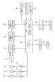
図1(A),(B)は、本発明を実施したデジタルスチルカメラ2の外観形状を示す斜視図であり、図2は、本発明を説明するうえで必要なデジタルスチルカメラ2の構成を示すブロック図である。デジタルスチルカメラ2の前面には、左右方向でスライド自在とされた略半円形状のレンズカバー3が取り付けられている。このレンズカバー3は、デジタルスチルカメラ2が不使用時、又は再生モードにあるときに図中右方の閉じ位置にスライドされ、デジタルスチルカメラ2の前面を保護している。また、デジタルスチルカメラ2で撮像を行なう時には、レンズカバー3が図中左方の開き位置にスライドされ、レンズ鏡筒4,ストロボ発光部5等が外部に露呈される。
1A and 1B are perspective views showing the external shape of a digital still camera 2 embodying the present invention. FIG. 2 shows the configuration of the digital still camera 2 necessary for explaining the present invention. FIG. A substantially
デジタルスチルカメラ2の上面には、左右方向にスライド操作される電源操作部材7と、上下方向で押圧操作されるシャッタボタン8とが設けられている。電源操作部材7の下には、その操作に応じてデジタルスチルカメラ2の電源をオン/オフする電源スイッチ9が組み込まれている。
On the upper surface of the digital still camera 2, a
シャッタボタン8の下には、2段階押圧式のシャッタスイッチ12が組み込まれている。シャッタボタン8が軽く押圧されてシャッタスイッチ12の1段目がオンすると、オートフォーカス機能と自動露出機能とが作動して、ピント合わせと露出設定とが行なわれる。次いで、シャッタボタン8を更に深く押し込むとシャッタスイッチ12の2段目がオンし、シャッタレリーズが実行される。
Below the
撮影モードにセットされた状態でデジタルスチルカメラ2の電源がオンされると、カメラ本体内に沈胴していたレンズ鏡筒4が前方に繰り出される。レンズ鏡筒4内には、例えばズームレンズ14及びフォーカスレンズ15等からなる撮影レンズ16と、絞り機構17とが組み込まれている。ズームレンズ14,フォーカスレンズ15,絞り機構17は、ドライバ回路を備えたモータ18,19,20によって駆動される。ズームモータ18は、レンズ鏡筒4の沈胴及び繰り出しの駆動源としても用いられる。
When the power of the digital still camera 2 is turned on in the shooting mode, the lens barrel 4 that has been retracted in the camera body is drawn forward. In the lens barrel 4, for example, a photographing
デジタルスチルカメラ2の背面には、表示モニタ22と、操作パネル23と、スピーカーからなる音声出力部24とが設けられている。表示モニタ22は、カラーLCDパネル26からなり、撮影済みの画像データを再生表示するとともに、撮影時にはビューファインダとしても使用される。
On the back surface of the digital still camera 2, a
操作パネル23は、モード操作部材28と、十字キー29と、キャンセルボタン30と、メニューボタン31と、表示ボタン32とからなる。モード操作部材28は、左右方向でスライド自在とされており、その奥にはモード操作部材28のスライド位置に応じて操作信号を出力するモードスイッチが組み込まれている。デジタルスチルカメラ2は、モード操作部材28のスライド操作によって、動画を撮影する動画撮影モード,撮影した静止画や動画を再生表示する再生モード,静止画の撮影を行なう静止画撮影モードの間で切り換えられる。
The
十字キー29は、上下方向に揺動操作される上下レバー34と、この上下レバー34の横に配置された左右ボタン35,36とからなる。上下レバー34と左右ボタン35,36とは、表示モニタ22上に表示されたカーソルや選択枠を上下左右方向に移動させる際に使用される。また、上下レバー34は撮影時及び再生時のズーム操作に、左右ボタン35,36は再生時のコマ送り等にも使用される。上下レバー34及び左右ボタン35,36の奥には、それぞれの操作部材によってオン/オフされるスイッチが組み込まれている。
The
メニューボタン31は、現在セットされているモードに応じた設定メニューを表示モニタ22上に呼び出す際に使用される。このメニューボタン31は、各種設定時に設定変更を実行するOKボタンとしても機能する。キャンセルボタン30は、各種設定時に設定変更を取りやめる際に使用される。表示ボタン32は、撮影モード時に表示モニタ22の表示のオン/オフを切り換えるとともに、表示モニタ22の表示設定を切り換える際に使用される。これらのキャンセルボタン30,メニューボタン31,表示ボタン32の奥には、各ボタンによってオン/オフされるスイッチが組み込まれている。
The
デジタルスチルカメラ2が静止画撮影モードにあるときに、メニューボタン31が押されると、表示モニタ22には数種類の設定メニューが表示される。これらの設定メニューの中から、例えば「画質設定」というメニューを選択すると、表示モニタ22には「感度」,「明るさ」,「カラー」,「白バランス」等のメニューが表示される。
When the
「感度」設定とは、写真カメラのフイルム選択のように撮影感度を設定する機能である。メニューの中から「感度」を選択すると、図3(A)に示すように、表示モニタ22には「200」,「400」,「800」という感度設定値が表示される。この感度設定値は、写真フイルムのISO感度値を流用したものであり、数字が大きくなるほど高感度であることを表す。なお、本実施形態のデジタルスチルカメラ2では、中間の「400」が標準設定となっている。
The “sensitivity” setting is a function for setting a photographing sensitivity like selecting a film of a photo camera. When “sensitivity” is selected from the menu, sensitivity setting values “200”, “400”, and “800” are displayed on the
「明るさ」設定とは、デジタルスチルカメラにおいて決定された露出値に対して、補正を加える機能である。メニューの中から「明るさ」を選択すると、図3(B)に示すように、表示モニタ22には、例えば「−1」,「AUTO」,「+1」という露出補正値(EV)が表示される。なお、本実施形態のデジタルスチルカメラ2では、補正を行なわないことを表す「AUTO」が標準設定となっている。また、本来の露出補正機能では、例えば0.3EVステップで露出補正値が選択できるようになっているが、本実施形態では説明を簡単にするために、−1EVと+1EVのみ選択可能としている。
The “brightness” setting is a function for correcting the exposure value determined in the digital still camera. When “Brightness” is selected from the menu, as shown in FIG. 3B, the
「カラー」設定とは、最終的に生成される画像データのコントラストや色合い等を設定する機能である。メニューの中から「カラー」を選択すると、図3(C)に示すように、表示モニタ22には「B&W」,「スタンダード」,「クローム」というカラー設定名が表示される。「B&W」は、モノクロの画像データが得られる設定である。「スタンダード」は、標準的なコントラストや色味の画像データが得られる設定であり、本デジタルスチルカメラ2の標準設定となっている。「クローム」は、コントラストや色味が強調されて鮮やかな色合いの画像データが得られる設定である。 The “color” setting is a function for setting the contrast, hue, and the like of image data that is finally generated. When “Color” is selected from the menu, color setting names “B & W”, “Standard”, and “Chrome” are displayed on the display monitor 22 as shown in FIG. “B & W” is a setting for obtaining monochrome image data. “Standard” is a setting for obtaining standard contrast and color image data, and is a standard setting of the digital still camera 2. “Chrome” is a setting in which image data with vivid colors can be obtained with enhanced contrast and color.
「白バランス」設定とは、撮影時の環境を選択することによって、ホワイトバランスを手動設定する機能である。メニューの中から「白バランス」を選択すると、図3(D)に示すように、表示モニタ22には、例えば「晴れ」,「AUTO」,「曇り」という設定値が表示される。「晴れ」や「曇り」は、屋外撮影時の天候を表す。また、「AUTO」では、デジタルスチルカメラ2が被写体輝度等から自動的に白バランスを設定する。 The “white balance” setting is a function for manually setting the white balance by selecting an environment at the time of shooting. When “white balance” is selected from the menu, as shown in FIG. 3D, the display monitor 22 displays setting values such as “clear”, “AUTO”, and “cloudy”, for example. “Sunny” and “cloudy” indicate the weather during outdoor shooting. In “AUTO”, the digital still camera 2 automatically sets the white balance based on subject brightness and the like.
デジタルスチルカメラ2の側面には、蓋部材41によって開閉されるメモリカードスロット38が設けられている。メモリカードスロット38には、周知のメモリカード39が挿入される。メモリカードスロット38の奥には、挿入されたメモリカード39に電気的に接続するコネクタが組み込まれており、このコネクタには、メモリカード39に対して画像データの読み書きを行なうメディアコントローラ40が接続されている。また、デジタルスチルカメラ2の底面には、電源となる電池がセットされる電池収納室が設けられている。この電池収納室は、開閉自在な電池蓋42によって塞がれている。
A
レンズ鏡筒4の背後には、CCD固体撮像素子45が配置されている。ズームレンズ14とフォーカスレンズ15とを通った被写体画像は、CCD固体撮像素子45の受光面上に結像されて撮像される。CCD固体撮像素子45は、撮像した被写体画像を光電変換して、2系統のアナログ信号を出力する。また、CCD固体撮像素子45は、シャッタスイッチ12の操作に応じてシャッタレリーズ動作を行なう電子シャッタ機能を備えている。
A CCD solid-
図4は、CCD固体撮像素子45の受光面の構成を概略的に示す説明図である。CCD固体撮像素子45の受光面47には、1つの画素を構成する受光部48が一定のピッチで複数配列されている。光電変換素子からなる受光部48はハニカム形状をしており、主感光部48aと、この主感光部48aよりも受光面積が小さい副感光部48bとからなる。CCD固体撮像素子45は、主感光部48aに蓄積された電荷からなる主出力信号Mと、副感光部48bに蓄積された電荷からなる副出力信号Sとを出力し、アナログ処理回路50に入力する。
FIG. 4 is an explanatory diagram schematically showing the configuration of the light receiving surface of the CCD solid-
アナログ処理回路50は、CCDドライバや、相関2重サンプリング回路(CDS),オートゲインコントローラ(AGC),ADコンバータ(ADC)等からなる、いわゆるアナログ・フロント・エンド回路である。CCD固体撮像素子45から入力されたアナログの主出力信号Mと副出力信号Sは、アナログ処理回路50によってRGBのデジタル信号に変換され、それぞれ高感度画像信号Hと低感度画像信号Lとして画像信号処理回路52に入力される。
The
図5は、CCD固体撮像素子45への露光量に対する高感度画像信号Hと低感度画像信号Lの出力レベル(階調レベル)を示すグラフである。8ビットの高感度画像信号Hが飽和する信号レベルHmax が、階調レベル255となる。主感光部48aは、少ない入射光量で飽和レベルまで達する。そのため、飽和レベル以上の光量を受光しても高感度画像信号Hの信号レベルは増加せず、ダイナミックレンジは狭いものとなる。これに対し副感光部48bは、主感光部48aよりも飽和レベルLmax は低いものの、入射光量に対する感度が鈍いため、低感度画像信号Lのダイナミックレンジは広くなる。
FIG. 5 is a graph showing output levels (gradation levels) of the high-sensitivity image signal H and the low-sensitivity image signal L with respect to the exposure amount to the CCD solid-
図6は、画像信号処理回路52の構成を示すブロック図である。画像信号処理回路52には、高感度画像信号Hと低感度画像信号Lとを処理するために、マトリクス補正部54a,54b、ホワイトバランス(WB)補正部55a,55b、ゲイン補正部56a,56b、ガンマ補正部57a,57b等からなる2種類の補正系統が設けられている。また、補正された高感度画像信号Hと低感度画像信号Lとを合成して合成画像信号Cを生成する画像合成処理部58と、RGB/YC変換部59とが設けられている。
FIG. 6 is a block diagram showing a configuration of the image
マトリクス補正部54a、54bは、リニアマトリクス変換式に基づいて、高感度画像信号Hと低感度画像信号Lとに色相補正を行なう。WB補正部55a,55bは、色相補正後の高感度画像信号Hと低感度画像信号Lとのホワイトバランスを調整する。ゲイン補正部56a,56bは、感度設定等に応じて高感度画像信号Hと低感度画像信号Lのゲインを調整する。ホワイトバランス補正やゲイン補正は、標準設定では自動的に実施されるが、「画質調整」メニューによってマニュアル設定することも可能である。ガンマ補正部57a、57bは、ホワイトバランス調整後の高感度画像信号Hと低感度画像信号Lに対してガンマ補正を行う。ガンマ補正後の高感度画像信号Hと低感度画像信号Lは、画像合成処理部58に送信される。
The
画像合成処理部58は、補正された高感度画像信号Hと低感度画像信号Lとを合成する。この合成処理は、高感度画像信号Hと低感度画像信号Lとを所定の比率で加算して、高感度画像信号Hの階調レベルと同じ階調レベルの合成画像信号Cを生成する。図5に示すように、これにより、合成画像信号Cは高感度画像信号Hと同じ階調幅を有しながら、低感度画像信号Lと同レベルの広いダイナミックレンジを得ることができる。
The image
また、画像合成処理部58には、システムコントローラ60から合成パラメータPが入力される。この合成パラメータPとは、高感度画像信号Hと低感度画像信号Lとの合成する際の比率を画像合成処理部58に指示するパラメータである。合成パラメータPは、上述した「画質設定」メニューにおいて感度や明るさが設定された時に、その設定内容に合わせて変更される。
Further, the composition parameter P is input from the
例えば、「感度」メニューで感度が標準設定値である「400」から「800」に変更された場合、画像合成処理部58に入力される合成パラメータPは、高感度画像信号Hの合成比率が高くされたものとなる。また、これとは逆に感度が「400」から「200」に変更されると、合成パラメータPは低感度画像信号Lの合成比率が高められたものとなる。
For example, when the sensitivity is changed from “400”, which is the standard setting value, to “800” in the “sensitivity” menu, the composition parameter P input to the image
図7のグラフは、合成パラメータPによって変化する合成画像信号Cを表している。合成画像信号Cは、感度が「400」の時の合成パラメータPによって生成されたものである。これに対し、合成画像信号C1及びC2は、感度が「800」及び「200」の時の合成パラメータPによって生成されたものである。このグラフから分かるように、感度が高感度側に設定されると合成画像信号C1は低輝度域の感度が高くなる。逆に低感度側に設定されると、合成画像信号C2は感度よりも階調表現を優先したものとなる。 The graph of FIG. 7 represents the composite image signal C that varies depending on the composite parameter P. The composite image signal C is generated by the composite parameter P when the sensitivity is “400”. On the other hand, the composite image signals C1 and C2 are generated by the composite parameter P when the sensitivity is “800” and “200”. As can be seen from this graph, when the sensitivity is set to the high sensitivity side, the composite image signal C1 has high sensitivity in the low luminance region. Conversely, when set to the low sensitivity side, the composite image signal C2 gives priority to gradation expression over sensitivity.
また、「画質設定」メニューの「明るさ」設定で露出補正が行なわれた場合にも、この露出補正値に応じた合成比率の合成パラメータPが画像合成処理部58に入力される。例えば、露出補正値「−1」が選択された場合には、高感度画像信号Hの合成比率のほうが高くされた合成パラメータPが画像合成処理部58に入力され、図7の合成画像信号C1に近似した合成画像信号が生成される。同様に、露出補正値「+1」が選択された場合には、低感度画像信号Lの合成比率が高められた合成パラメータPが画像合成処理部58に入力され、合成画像信号C2に近似した合成画像信号が生成される。
Also, when exposure correction is performed with the “brightness” setting in the “image quality setting” menu, a composite parameter P having a composite ratio corresponding to the exposure correction value is input to the image
なお、本実施形態では詳しく説明しないが、「画質調整」メニューの「カラー」設定や「白バランス」設定が変更された時にも、その設定内容に合わせた合成パラメータPが画像合成処理部58に入力される。また、「感度」,「明るさ」,「カラー」,「白バランス」のそれぞれが同時に設定変更された場合には、その複合的な設定の組み合わせに対応した合成パラメータPを用意しておくことで、適切な合成比率の合成処理を行なうことができる。また、複合的な設定変更に対応した合成パラメータPを用意せずに、各設定の合成パラメータから演算処理をして、適切な合成比率の合成パラメータを求めてもよい。
Although not described in detail in the present embodiment, even when the “color” setting or “white balance” setting of the “image quality adjustment” menu is changed, the synthesis parameter P according to the setting content is input to the image
RGB/YC変換部59は、RGBからなる合成画像信号Cを輝度データと色差データとからなるYC画像データに変換する。圧縮伸長処理回路62は、YC画像データを所定のファイル形式(例えばJPEG形式)に圧縮変換する。圧縮された画像データは、メディアコントローラ40によってメモリカード39に記録される。再生モードにおいて、メモリカード39内の画像データを表示モニタ22に再生表示する場合には、メモリカード39から読み出された画像データが圧縮伸長処理回路62によって伸長され、LCDドライバ64によってLCDパネル26に再生表示される。
The RGB /
システムコントローラ60は、デジタルスチルカメラ2の全体を制御する。システムコントローラ60は、例えばマイクロコンピュータからなり、CPUの他に、制御プログラムや各種設定データ等が記憶されたROM66aと、制御時に生じた種々のデータが一時的に記憶される作業用のRAM66b等を備えている。
The
ROM66aには、デジタルスチルカメラ2の「画質調整」メニューの設定内容に対応した合成パラメータPと、各設定が複合的に行なわれた場合の合成パラメータPとが記憶されている。そして、「画質調整」メニューで設定が変更された場合には、システムコントローラ60がROM66aから設定内容に対応する合成パラメータPを読み出して、画像合成処理部58に入力する。
The
次に、上記実施形態の作用について、図8のフローチャート参照しながら説明する。デジタルスチルカメラ2を把持してレンズ鏡筒4を被写体に向けると、CCD固体撮像素子45で撮影された画像が表示モニタ22にスルー表示される。所定のタイミングでシャッタボタン8を押下すると、シャッタスイッチ12のオン信号がシステムコントローラ60に入力される。
Next, the operation of the above embodiment will be described with reference to the flowchart of FIG. When the digital still camera 2 is held and the lens barrel 4 is pointed at the subject, an image captured by the CCD solid-
システムコントローラ60は、シャッタスイッチ12の1段目がオンした時のYC画像データに基づいて被写体距離と露出値とを算出する。そして、シャッタスイッチ12の2段目がオンした時に、被写体距離に基づいてフォーカシングを行ない、露出値に基づいて絞り機構17やCCD固体撮像素子45の電子シャッタ機能を作動させて撮影を行なう。
The
CCD固体撮像素子45からは、主感光部48aに蓄積された電荷からなる主出力信号Mと、副感光部48bに蓄積された電荷からなる副出力信号Sとが出力され、アナログ処理回路50に入力される。アナログ処理回路50に入力された主出力信号M及び副出力信号Sは、デジタルの高感度画像信号H及び低感度画像信号Lに変換されて、画像信号処理回路52に入力される。
From the CCD solid-
画像信号処理回路52は、高感度画像信号H及び低感度画像信号Lに対して、マトリクス補正,ホワイトバランス補正,ゲイン補正,ガンマ補正を施し、画像合成処理部58に入力する。画像合成処理部58は、システムコントローラ60から入力された合成パラメータPに基づいて、所定の合成比率で高感度画像信号Hと低感度画像信号Lとを合成する。
The image
「画質調整」メニューにおいて設定変更がなされていない場合には、高感度画像信号Hと低感度画像信号Lとが標準の合成比率で加算されて、図7に示す標準の合成画像信号Cが生成される。また、「感度」設定が高感度である「800」に設定されている場合には、合成パラメータPの高感度画像信号Hの合成比率が高くなるため、低輝度域の感度が高くされた合成画像信号C1が生成される。また、低感度である「200」に設定されている場合には、合成パラメータPの低感度画像信号Lの合成比率が高くなるため、階調表現が優先された合成画像信号C2が生成される。 When the setting is not changed in the “image quality adjustment” menu, the high-sensitivity image signal H and the low-sensitivity image signal L are added at a standard composition ratio to generate a standard composite image signal C shown in FIG. Is done. When the “sensitivity” setting is set to “800”, which is high sensitivity, the composition ratio of the high-sensitivity image signal H of the composition parameter P is increased, so that the composition in which the sensitivity in the low luminance region is increased. An image signal C1 is generated. In addition, when “200”, which is low sensitivity, is set, the composite ratio of the low sensitivity image signal L of the composite parameter P becomes high, and thus the composite image signal C2 giving priority to gradation expression is generated. .
また、「明るさ」設定によって露出補正が行なわれた場合にも、図7の合成画像信号C1又はC2に近似した合成画像が生成される。さらに、「感度」,「明るさ」,「カラー」,「白バランス」等の設定項目が同時に設定変更された場合でも、その複合的な設定変更に対応した合成比率で合成画像信号が生成される。 Further, even when exposure correction is performed according to the “brightness” setting, a composite image approximating the composite image signal C1 or C2 in FIG. 7 is generated. Furthermore, even if setting items such as “sensitivity”, “brightness”, “color”, and “white balance” are changed simultaneously, a composite image signal is generated with a composite ratio corresponding to the combined setting change. The
RGBからなる合成画像信号Cは、RGB/YC変換部59によってYC画像データに変換され、圧縮伸長処理回路62に入力される。圧縮伸長処理回路62によって所定のファイル形式(例えばJPEG形式)に圧縮変換された画像データは、メディアコントローラ40によってメモリカード39に記録される。
The composite image signal C composed of RGB is converted into YC image data by the RGB /
このように、画質調整に連動して高感度画像信号Hと低感度画像信号Lとの合成比率を変更するようにしたので、デジタルスチルカメラ2に対する知識に乏しいユーザーであっても、合成比率の変更による効果を得ることができる。 As described above, since the combination ratio of the high-sensitivity image signal H and the low-sensitivity image signal L is changed in conjunction with the image quality adjustment, even if the user has little knowledge of the digital still camera 2, the combination ratio The effect of the change can be obtained.
また、従来のデジタルスチルカメラの感度設定はゲイン調整だけで行なっていたため、高感度に設定すると画質が劣化していた。しかしながら、本発明は、高感度画像信号Hと低感度画像信号Lとの合成比率を変更することによって感度調整を補助することができるので、ゲイン調整量が少なくなり、高感度時の画質向上を図ることができる。更に、低感度設定時には階調表現が滑らかになるため、画質が向上する。 In addition, since the sensitivity setting of a conventional digital still camera is performed only by gain adjustment, the image quality deteriorates when the sensitivity is set to a high sensitivity. However, since the present invention can assist the sensitivity adjustment by changing the synthesis ratio of the high-sensitivity image signal H and the low-sensitivity image signal L, the gain adjustment amount is reduced and the image quality at the time of high sensitivity is improved. Can be planned. Furthermore, since the gradation expression becomes smooth when the low sensitivity is set, the image quality is improved.
また、従来の露出補正では、プラス補正をしたときには白飛びが発生し、マイナス補正では黒潰れが発生することがあった。しかし、プラス補正時には低感度画像信号Lの合成比率を高め、マイナス補正時には高感度画像信号Hの合成比率を高めるようにしたので、露出補正の効果を減殺することなく、白飛びと黒潰れの発生を防止することができる。 In addition, in the conventional exposure correction, overexposure occurs when plus correction is performed, and black crushing occurs when minus correction is performed. However, at the time of increased exposure increases the synthesis ratio of the low-sensitivity image signal L, and when the negative correction since to increase the mixing ratio of the high-sensitivity image signal H, without counteracting the effects of exposure correction, overexposure and black collapse of the Occurrence can be prevented.
なお、上記実施形態では、感度,明るさ,カラー,白バランスの設定メニューにおいて、選択項目を3種類ずつしか記載していないが、本発明は、もっと多数の選択項目に対応させることができる。 In the above embodiment, only three types of selection items are described in the sensitivity, brightness, color, and white balance setting menus. However, the present invention can deal with a larger number of selection items.
なお、上記実施形態では、デジタルスチルカメラを例に説明したが、主感光部と副感光部と有するCCD固体撮像素子を用いている撮像装置ならば、本発明を適用することができる。 In the above embodiment, the digital still camera has been described as an example. However, the present invention can be applied to any imaging apparatus using a CCD solid-state imaging device having a main photosensitive portion and a sub-photosensitive portion.
2 デジタルスチルカメラ
22 表示モニタ
23 操作パネル
45 CCD固体撮像素子
48 受光部
48a 主感光部
48b 副感光部
52 画像信号処理回路
58 画像合成処理部
60 システムコントローラ
2 Digital still
Claims (6)
前記主感光部から出力された主出力信号と、前記副感光部から出力された副出力信号とを所定の合成比率で合成して画像データを生成する合成手段と、
感度を設定する感度設定手段と、
前記感度設定手段が低感度側に設定されているときに前記副出力信号の合成比率を高くし、前記感度設定手段が高感度側に設定されているときには前記主出力信号の合成比率を高くする合成比率変更手段とを備えたことを特徴とする撮像装置。 A main light-sensitive portion, and a solid-state imaging device which has been arrayed pixels consisting of said main photosensitive unit low sensitivity by-photosensitive portion than,
A main output signal output from the main light-sensitive unit, a synthesizing means for generating image data by synthesizing the sub output signal output from the sub-light-sensitive portions in a predetermined combination ratio,
Sensitivity setting means for setting the sensitivity;
When the sensitivity setting means is set to the low sensitivity side, the synthesis ratio of the sub output signal is increased, and when the sensitivity setting means is set to the high sensitivity side, the synthesis ratio of the main output signal is increased . imaging apparatus being characterized in that a synthesis ratio changing means.
前記主感光部から出力された主出力信号と、前記副感光部から出力された副出力信号とを所定の合成比率で合成して画像データを生成する合成手段と、
露出を補正する露出補正手段と、
前記露出補正手段がプラス側に補正されているときに前記副出力信号の合成比率を高くし、前記露出補正手段がマイナス側に設定されているときには前記主出力信号の合成比率を高くする合成比率変更手段とを備えたことを特徴とする撮像装置。 A solid-state imaging device in which a large number of pixels each having a main photosensitive portion and a sub-photosensitive portion having a lower sensitivity than the main photosensitive portion are arranged;
A synthesizing unit that synthesizes the main output signal output from the main photosensitive unit and the sub output signal output from the sub photosensitive unit at a predetermined synthesis ratio, and generates image data;
Exposure correction means for correcting exposure; and
A composite ratio that increases the composite ratio of the secondary output signal when the exposure correction means is corrected to the positive side, and increases the composite ratio of the main output signal when the exposure correction means is set to the negative side. An image pickup apparatus comprising: a changing unit .
感度設定手段が低感度側に設定されているときに前記副出力信号の合成比率が高くなり、前記感度設定手段が高感度側に設定されているときには前記主出力信号の合成比率が高くなるように、前記主出力信号と前記副出力信号との合成比率を変更し、When the sensitivity setting means is set to the low sensitivity side, the composite ratio of the sub output signal is high, and when the sensitivity setting means is set to the high sensitivity side, the composite ratio of the main output signal is high. And changing the synthesis ratio of the main output signal and the sub output signal,
前記合成比率に基づいて前記主出力信号と前記副出力信号とを合成し、画像データを生成することを特徴とする撮像装置の制御方法。A control method for an imaging apparatus, comprising: synthesizing the main output signal and the sub output signal based on the synthesis ratio to generate image data.
露出補正手段がプラス側に補正されているときに前記副出力信号の合成比率が高くなり、前記露出補正手段がマイナス側に設定されているときには前記主出力信号の合成比率が高くなるように、前記主出力信号と前記副出力信号との合成比率を変更し、When the exposure correction means is corrected to the plus side, the composition ratio of the sub output signal is high, and when the exposure correction means is set to the minus side, the composition ratio of the main output signal is high. Changing the synthesis ratio of the main output signal and the sub output signal;
前記合成比率に基づいて前記主出力信号と前記副出力信号とを合成し、画像データを生成することを特徴とする撮像装置の制御方法。A control method for an imaging apparatus, comprising: synthesizing the main output signal and the sub output signal based on the synthesis ratio to generate image data.
前記感度設定手段が低感度側に設定された場合に、前記副出力信号の合成比率を高くし、前記感度設定手段が高感度側に設定された場合には、前記主出力信号の合成比率を高くすることを特徴とする撮像装置の制御方法。 A main light-sensitive portion, and a solid-state imaging device which has been arrayed pixels consisting of a low-sensitivity sub-photosensitive portion than the main light-sensitive unit, output main output signal output from the main light-sensitive part from the auxiliary photosensitive section changes and combining means for generating image data by synthesizing the sub output signal, and sensitivity setting means for setting the sensitivity, the mixing ratio of the sub-output signal and the main output signal in accordance with the setting of the sensitivity setting means In an imaging device comprising a composition ratio changing means for
When the sensitivity setting means is set to the low sensitivity side, when said higher the mixing ratio of the sub output signal, the sensitivity setting means is set to the high sensitivity side, the mixing ratio of the main output signal A method for controlling an imaging apparatus, characterized by being made high.
前記露出補正手段がプラス側に補正された場合に、前記副出力信号の合成比率を高くし、前記露出補正手段がマイナス側に設定された場合には、前記主出力信号の合成比率を高くすることを特徴とする撮像装置の制御方法。 A main light-sensitive portion, and the solid-state imaging device arranging a large number of pixels composed of a low-sensitivity sub-photosensitive portion than the main light-sensitive unit, output main output signal output from the main light-sensitive part from the auxiliary photosensitive section changes and combining means for generating image data by synthesizing the sub output signal, and exposure correction means for correcting the exposure, the mixing ratio of the sub-output signal and the main output signal in accordance with the setting of the exposure correction means In an imaging device comprising a composition ratio changing means for
If the exposure correction means is corrected to the plus side, a higher mixing ratio of the said sub output signal, when said exposure correction means is set on the minus side is set higher, the mixing ratio of the main output signal And a method of controlling the imaging apparatus.
Priority Applications (2)
| Application Number | Priority Date | Filing Date | Title |
|---|---|---|---|
| JP2003279920A JP4301890B2 (en) | 2003-07-25 | 2003-07-25 | IMAGING DEVICE AND IMAGING DEVICE CONTROL METHOD |
| US10/896,025 US20050018059A1 (en) | 2003-07-25 | 2004-07-22 | Imaging device and control method thereof |
Applications Claiming Priority (1)
| Application Number | Priority Date | Filing Date | Title |
|---|---|---|---|
| JP2003279920A JP4301890B2 (en) | 2003-07-25 | 2003-07-25 | IMAGING DEVICE AND IMAGING DEVICE CONTROL METHOD |
Publications (2)
| Publication Number | Publication Date |
|---|---|
| JP2005045713A JP2005045713A (en) | 2005-02-17 |
| JP4301890B2 true JP4301890B2 (en) | 2009-07-22 |
Family
ID=34074762
Family Applications (1)
| Application Number | Title | Priority Date | Filing Date |
|---|---|---|---|
| JP2003279920A Expired - Fee Related JP4301890B2 (en) | 2003-07-25 | 2003-07-25 | IMAGING DEVICE AND IMAGING DEVICE CONTROL METHOD |
Country Status (2)
| Country | Link |
|---|---|
| US (1) | US20050018059A1 (en) |
| JP (1) | JP4301890B2 (en) |
Families Citing this family (7)
| Publication number | Priority date | Publication date | Assignee | Title |
|---|---|---|---|---|
| JP2006067181A (en) * | 2004-08-26 | 2006-03-09 | Fuji Photo Film Co Ltd | Camera system |
| JP4733419B2 (en) | 2005-04-26 | 2011-07-27 | 富士フイルム株式会社 | Composite image data generation apparatus, control method therefor, and control program therefor |
| JP2008301389A (en) * | 2007-06-04 | 2008-12-11 | Panasonic Corp | Image processing lsi and imaging device |
| US8027591B2 (en) * | 2007-10-29 | 2011-09-27 | Cubic Corporation | Resonant quantum well modulator driver |
| JP5310247B2 (en) * | 2009-05-13 | 2013-10-09 | ソニー株式会社 | Image processing apparatus and method, and program |
| JP5952574B2 (en) * | 2012-02-02 | 2016-07-13 | キヤノン株式会社 | Image processing apparatus and control method thereof |
| JP5952573B2 (en) * | 2012-02-02 | 2016-07-13 | キヤノン株式会社 | Image processing apparatus and control method thereof |
Family Cites Families (3)
| Publication number | Priority date | Publication date | Assignee | Title |
|---|---|---|---|---|
| JP3949903B2 (en) * | 2001-04-09 | 2007-07-25 | 東芝エルエスアイシステムサポート株式会社 | Imaging apparatus and imaging signal processing method |
| US7508421B2 (en) * | 2002-06-24 | 2009-03-24 | Fujifilm Corporation | Image pickup apparatus and image processing method |
| JP2005072965A (en) * | 2003-08-25 | 2005-03-17 | Fuji Photo Film Co Ltd | Image compositing method, solid-state image pickup device and digital camera |
-
2003
- 2003-07-25 JP JP2003279920A patent/JP4301890B2/en not_active Expired - Fee Related
-
2004
- 2004-07-22 US US10/896,025 patent/US20050018059A1/en not_active Abandoned
Also Published As
| Publication number | Publication date |
|---|---|
| JP2005045713A (en) | 2005-02-17 |
| US20050018059A1 (en) | 2005-01-27 |
Similar Documents
| Publication | Publication Date | Title |
|---|---|---|
| JP3551123B2 (en) | Electronic camera | |
| JP4904108B2 (en) | Imaging apparatus and image display control method | |
| JP4787180B2 (en) | Imaging apparatus and imaging method | |
| JP4679685B2 (en) | Digital camera composition auxiliary frame selection method and digital camera | |
| JP4730553B2 (en) | Imaging apparatus and exposure control method | |
| JP4791165B2 (en) | camera | |
| JP5642344B2 (en) | Image processing apparatus, image processing method, and image processing program | |
| JP2005062370A (en) | Imaging apparatus | |
| US20060055991A1 (en) | Image capture apparatus and image capture method | |
| JP2008053931A (en) | Imaging apparatus | |
| US7423682B2 (en) | Digital camera | |
| JP2009071592A (en) | Imaging apparatus and imaging control method | |
| JP2007235640A (en) | Photographing device and method | |
| JP4301890B2 (en) | IMAGING DEVICE AND IMAGING DEVICE CONTROL METHOD | |
| JP3967510B2 (en) | Digital camera | |
| JP4114707B2 (en) | Imaging device | |
| JP2008160190A (en) | Imaging apparatus, and method thereof | |
| JP4761039B2 (en) | Imaging device | |
| JP2009118052A (en) | Image signal processing method and apparatus | |
| JP2005244423A (en) | Photographing apparatus | |
| JP2010212827A (en) | Imager, and control method for imager | |
| JP2008160290A (en) | Imaging apparatus, and imaging method | |
| JP2007110221A (en) | Imaging apparatus | |
| JP2007226141A (en) | Photographing device and method | |
| JP2003116047A (en) | Image pickup device and photograph controlling method |
Legal Events
| Date | Code | Title | Description |
|---|---|---|---|
| A621 | Written request for application examination |
Free format text: JAPANESE INTERMEDIATE CODE: A621 Effective date: 20060303 |
|
| A711 | Notification of change in applicant |
Free format text: JAPANESE INTERMEDIATE CODE: A712 Effective date: 20061219 |
|
| A131 | Notification of reasons for refusal |
Free format text: JAPANESE INTERMEDIATE CODE: A131 Effective date: 20080213 |
|
| A521 | Request for written amendment filed |
Free format text: JAPANESE INTERMEDIATE CODE: A523 Effective date: 20080409 |
|
| TRDD | Decision of grant or rejection written | ||
| A01 | Written decision to grant a patent or to grant a registration (utility model) |
Free format text: JAPANESE INTERMEDIATE CODE: A01 Effective date: 20090415 |
|
| A01 | Written decision to grant a patent or to grant a registration (utility model) |
Free format text: JAPANESE INTERMEDIATE CODE: A01 |
|
| A61 | First payment of annual fees (during grant procedure) |
Free format text: JAPANESE INTERMEDIATE CODE: A61 Effective date: 20090421 |
|
| FPAY | Renewal fee payment (event date is renewal date of database) |
Free format text: PAYMENT UNTIL: 20120501 Year of fee payment: 3 |
|
| R150 | Certificate of patent or registration of utility model |
Free format text: JAPANESE INTERMEDIATE CODE: R150 |
|
| FPAY | Renewal fee payment (event date is renewal date of database) |
Free format text: PAYMENT UNTIL: 20130501 Year of fee payment: 4 |
|
| FPAY | Renewal fee payment (event date is renewal date of database) |
Free format text: PAYMENT UNTIL: 20140501 Year of fee payment: 5 |
|
| R250 | Receipt of annual fees |
Free format text: JAPANESE INTERMEDIATE CODE: R250 |
|
| R250 | Receipt of annual fees |
Free format text: JAPANESE INTERMEDIATE CODE: R250 |
|
| R250 | Receipt of annual fees |
Free format text: JAPANESE INTERMEDIATE CODE: R250 |
|
| R250 | Receipt of annual fees |
Free format text: JAPANESE INTERMEDIATE CODE: R250 |
|
| LAPS | Cancellation because of no payment of annual fees |