JP4300552B2 - Game machine - Google Patents

Game machine Download PDF

Info

Publication number
JP4300552B2
JP4300552B2 JP2002186782A JP2002186782A JP4300552B2 JP 4300552 B2 JP4300552 B2 JP 4300552B2 JP 2002186782 A JP2002186782 A JP 2002186782A JP 2002186782 A JP2002186782 A JP 2002186782A JP 4300552 B2 JP4300552 B2 JP 4300552B2
Authority
JP
Japan
Prior art keywords
ball
passage
rotating body
sphere
guide
Prior art date
Legal status (The legal status is an assumption and is not a legal conclusion. Google has not performed a legal analysis and makes no representation as to the accuracy of the status listed.)
Expired - Fee Related
Application number
JP2002186782A
Other languages
Japanese (ja)
Other versions
JP2003305245A (en
Inventor
高明 市原
篤 齋藤
Current Assignee (The listed assignees may be inaccurate. Google has not performed a legal analysis and makes no representation or warranty as to the accuracy of the list.)
Daiichi Co Ltd
Original Assignee
Daiichi Shokai Co Ltd
Priority date (The priority date is an assumption and is not a legal conclusion. Google has not performed a legal analysis and makes no representation as to the accuracy of the date listed.)
Filing date
Publication date
Application filed by Daiichi Shokai Co Ltd filed Critical Daiichi Shokai Co Ltd
Priority to JP2002186782A priority Critical patent/JP4300552B2/en
Publication of JP2003305245A publication Critical patent/JP2003305245A/en
Application granted granted Critical
Publication of JP4300552B2 publication Critical patent/JP4300552B2/en
Anticipated expiration legal-status Critical
Expired - Fee Related legal-status Critical Current

Links

Images

Landscapes

  • Pinball Game Machines (AREA)

Description

【0001】
【発明の属する技術分野】
この発明は、球(パチンコ球)を使用して遊技を行う遊技機、例えば、弾球遊技機(主としてパチンコ機)と呼ばれている遊技機や、コインに換え球を使用してスロットマシン遊技のような遊技を行う遊技機に関する。
【0002】
【従来の技術】
球(パチンコ球)を使用して遊技を行う遊技機においては、賞球や貸球の球数に対応する数の球を所定位置、例えば、払出通路を介して遊技機前側に設置された受け皿(上皿や下皿)に払い出すように構成する必要がある。このため、遊技機の所定位置には、球通路と、その球通路の下端の供給口から供給された球を受けてその球を払い出す回転体と、を有する球払出装置が配設されるようになっている。また、球払出装置の回転体の外周面には、球を受ける複数の球受部が所定の角度を隔てて設けられたスプロケット状に形成されているのが一般的である。
【0003】
【発明が解決しようとする課題】
ところで、球通路の下端の供給口から供給された球を回転体によって受け、その球を回転体の回転動作によって払い出すように構成すると、供給口と回転体の外周面との間に球が不測に噛み込んで回転体の回転が停止する、いわゆる球噛みによる不具合が発生する場合がある。このような球噛み発生時には、球通路の下端の供給口と回転体の外周面との間に噛み込んだ球を取り除く球噛み解消作業が必要となり、厄介であった。
【0004】
この発明の目的は、前記問題点に鑑み、球通路の供給口と回転体の外周面との間に球が不測に噛み込む不具合を防止することができる遊技機を提供することである。
【0005】
【課題を解決するための手段】
前記目的を達成するために、第1の発明に係る遊技機は、請求項1に記載のとおりの構成を要旨とするもので、球通路と、その球通路の下端の供給口から供給された球を受けてその球を払い出す回転体と、を有する球払出装置を備える。前記回転体は、複数個のスプロケット部と、凹円弧状の球受部と、が回転円周方向に交互に配置形成されると共に、その回転中心が前記供給口を通る縦中心線上に位置して払出用モータにより正逆方向に回転可能とされる。前記供給口の両側部には、球の直径寸法よりも僅かに大きい間隔寸法を隔てて対向し前記回転体に向けて球を案内する凸円弧面状に形成される案内部と、該案内部の下端部と連続する下側面に凹湾曲状に形成される押下面と、を有する一対の可動案内部材が、球案内位置と前記案内部が回転体から遠ざかる退避位置とに軸を中心に個々に回動可能に設けられると共に、前記一対の可動案内部材の間に跨って弾性体が配設される。前記一対の可動案内部材は、常には前記弾性体の左右同等な引張力によって前記案内部が対向する前記案内位置に付勢保持されるとともに、前記回転体の回転に伴っていずれか一方の可動案内部材と前記スプロケット部の外周面との間に球が噛み込まれて所定値以上の荷重が作用したときにはその噛み込まれた球と前記案内部の凸円弧面との当接により前記弾性体の引張力に抗して前記球案内位置から前記退避位置へと前記軸を中心にして回動変位し、前記案内部の凸円弧面と噛み込まれた球との当接状態がなくなったときには前記弾性体の引張力により前記押下面の凹湾曲面によって噛み込まれた球を押し下げるように前記退避位置から前記球案内位置へと前記軸を中心にして回動変位する構成にしてある。
【0006】
したがって、球通路の下端の供給口に供給された球は、可動案内部材の案内部に案内されて回転体に供給される。そして、回転体に供給され球は、同回転体の回転動作によって払い出される。回転体の回転動作によって球を払い出す際、供給口の可動案内部材と回転体の外周面との間に球が不測に噛み込もうとすることがある。球が噛み込もうとする所定値以上の荷重が可動案内部材に作用すると、可動案内部材は、弾性体を弾性変形させながら、その案内部が回転体の外周面から遠ざかる退避位置に向けて変位する。このため、供給口の可動案内部材と回転体の外周面との間に球が不測に噛み込んで回転体の回転が停止する、という球噛みによる不具合の発生を防止することができる。
【0007】
【0008】
【0009】
【0010】
【発明の実施の形態】
この発明の実施の形態を図面にしたがって説明する。球を使用して遊技を行う遊技機(例えばパチンコ機)を後方から表した図1において、遊技機1は、外枠2と、その外枠2の前側にヒンジ機能によって開閉可能に装着され方形枠状の前枠3とを主体として構成されている。前枠3の前側には、周知のようにガラス板を有する開閉扉、球B(パチンコ球)が貯留可能な上皿、下皿、球発射用のハンドル装置等が配設されている。前枠3の後面には、その枠開口部の周縁部において遊技盤装着枠が固定状態で組み付けられ、その遊技盤装着枠の枠内には遊技盤(図示しない)が着脱可能に嵌込まれ、その遊技盤の後面の周囲が機構板10(裏セット板、裏機構板等とも呼ばれる)によって押されられた状態で固定されている。なお、遊技盤の前面の遊技領域には、各種入賞装置、役物装置、図柄表示装置、ゲート口等が適宜に配設されている。
【0011】
機構板10の後面の上部には、球Bが貯留される球タンク11と、その球タンク11の一端寄りの下部に接続されるタンクレール12とがそれぞれ装着されている。タンクレール12は、その一側から他側(図1に向かって左側から右側)に向けて球Bが前後2列に整列されながら流れる傾斜状の球送り通路13が形成され、その球送り通路13の下傾端を球送出部としている。機構板10の後面の片側(図1に向かって右側)には、タンクレール12の球送出部に隣接してユニット装着部が設けられ、そのユニット装着部には球払出装置30を構成する1つのユニット状の球払出装置ユニット31が着脱可能に装着されている。
【0012】
また、機構板10の後側には、球払出装置ユニット31の賞球用通路72並びに貸球用通路73の下流端を合流してこれら賞球用通路72及び貸球用通路73から払い出された球Bを所定位置まで導く前後2列の本体側払出通路14が形成されている。また、本体側払出通路14の下流部には球Bを上皿に導く上皿用球通路16が設けられている。また、上皿用球通路16には上皿用球溜部17が形成され、その上皿用球溜部17の一側には、上皿の球Bが満杯になったときに上皿用球溜部17の球Bを下皿に導く下皿用球通路19が形成されている。また、機構板10の後側には、球タンク11及びタンクレール12の球Bを球払出装置ユニット31の一部に設けられた排出通路50を介して機外に排出するための本体側排出通路21が形成されている。
【0013】
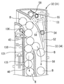
図2〜図5に示すように、球払出装置ユニット31は、ユニットケース32と、そのユニットケース32に組み付けられる通路切換部材52、可動案内部材60、回転体82、払出用モータ80、各種検出器等を備えている。ユニットケース32は、合成樹脂の射出成形等によってそれぞれ形成されかつネジ等によって分離可能に結合された第1通路構成部材33、第2通路構成部材34及び第3通路構成部材35の3部品を主体として構成されている。図2と図5に示すように、ユニットケース32内には、前後2列でかつ縦通路状をなす球通路40と、その球通路40の下端部に連通する供給口46とがそれぞれ区画形成されている。
【0014】
また、この実施の形態において、図5に示すように、ユニットケース32内には、前後2列の球通路40の片側にそれぞれ隣接して排出通路50が区画形成されている。この排出通路50と球通路40との上部境界部には、通路切換部材52が操作ロック部材55によって第1位置と第2位置とに配置切換可能に配設されている。そして、図5に示すように、操作ロック部材55によって通路切換部材52が第1位置に配置されてロックされたときには、タンクレール12の球送出部から送られる球Bが排出通路50に流れることなく球通路40にのみ流れるようになっている。また、図6に示すように、操作ロック部材55が上方に操作されてロック解除されたときには、タンクレール12の球送出部から球通路40の上部に向けて流れる球Bの流圧を受けて通路切換部材52が軸53を中心として回動し、第2位置に配置切り換えされる。これによって、球通路40の上部に向けて流れる球Bが排出通路50に流れるようになっている。なお、操作ロック部材55はバネ58によって下方のロック位置に向けて弾発されており、その下端部には、通路切換部材52の所定位置に形成された係合部54と係脱可能に係合して通路切換部材52を第1位置と第2位置とに択一的にロックするロック部56が形成されている。
【0015】
図5に示すように、ユニットケース32内の下部には、供給口46に連通する回転体配設部が形成され、その回転体配設部には、球Bを受けて払い出すスプロケット状の回転体82が正逆方向に回転可能に配設されている。そして、ユニットケース32内の下部には、回転体82の外周面の片側(図5に向かって左側)に賞球用通路72が反対側に貸球用通路73がそれぞれ前後2列に区画形成されている。
【0016】
すなわち、図2と図5に示すように、第1通路構成部材33と第2通路構成部材34との間には、第1通路構成部材33の基板部と第2通路構成部材34の基板部によって前側の球通路40、前側の供給口46、前側の賞球用通路72、前側の貸球用通路73及び前側の排出通路50の各前・後壁がそれぞれ形成されている。さらに、第1通路構成部材33の基板部によって回転体配設部の前側壁が形成されるとともに、第2通路構成部材34には、回転体82が貫挿される孔が形成されている。また、第1通路構成部材33の基板部と第2通路構成部材34の基板部とのうち、少なくとも一方には、前側の球通路40と前側の排出通路50とを隣接して区画形成する通路壁41、42、51がそれぞれ形成されるとともに、前側の賞球用通路72、前側の貸球用通路73の外側壁48がそれぞれ形成されている。さらに、第1通路構成部材33の基板部と第2通路構成部材34の基板部とのうち、少なくとも一方には、回転体82の下方に隣接して前側の賞球用通路72と前側の貸球用通路73とを区画する分岐壁59が形成されている。
【0017】
また、第2通路構成部材34と第3通路構成部材35との間においても、略同様にして、第2通路構成部材34の基板部と第3通路構成部材35の基板部によって後側の球通路40、後側の供給口46、後側の賞球用通路72、後側の貸球用通路73及び後側の排出通路50の各前・後壁がそれぞれ形成されるとともに、第3通路構成部材35の基板部によって回転体配設部の後側壁48、49が形成されている。また、第2通路構成部材34の基板部と第3通路構成部材35の基板部とのうち、少なくとも一方には、後側の球通路40と後側の排出通路50とを隣接して区画形成する通路壁41、42、51がそれぞれ形成されるとともに、後側の賞球用通路72、後側の貸球用通路73の外側壁が形成されている。さらに、第2通路構成部材34の基板部と第3通路構成部材35の基板部とのうち、少なくとも一方には、回転体82の下方に隣接して後側の賞球用通路72と後側の貸球用通路73とを区画する分岐壁59が形成されている。
【0018】
図5〜図8に示すように、前後2列の縦通路状をなす球通路40は、その上端部(上流端)の補充口が、ユニットケース32の上端部側方に開口するとともに、タンクレール12の前後2列の球送り通路13の下傾端の球送出部に臨んで連通されている。また、前後2列の球通路40の下端部(下流端)は、供給口46を介して回転体82に臨んでいる。また、球通路40は、上部から下部に向けて上通路部43、幅広通路部44及び絞り通路部45を順次連通して有する。また、上通路部43、幅広通路部44及び絞り通路部45に球Bが相互に接した状態でかつこれら各球Bが両通路壁41、42のいずれか一方の内壁面に接した状態で略ジグザグ状をなして一列状に配列されるようになっている。
【0019】
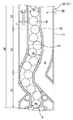
この実施の形態において、上通路部43は、側方(横方向)に開口する補充口から下方に向けて屈曲された逆L字状をなし、その上通路部43の通路幅W1は、球Bの直径寸法よりも1.2倍程度に大きく形成されている。上通路部43の下部に連続して形成された幅広通路部44はその略中央部が最大の通路幅W2を有しかつ直線に近い略湾曲状に形成され、その中央部の通路幅W2が最大で球Bの直径寸法よりも1.8倍程度(この実施の形態では1.5倍前後)だけ大きく形成されている。そして、幅広通路部44の上部の通路幅は、上通路部43の下部との間に段差が生じることがないように球Bの直径寸法よりも1.2倍程度に大きく形成されている。また、幅広通路部44の下部の通路幅は、絞り通路部45の上部との間の段差が生じることがないように球Bの直径寸法よりも1.3倍程度に大きく形成されている。
【0020】
また、幅広通路部44の下部に連続して形成された絞り通路部45は、幅広通路部44の横方向の変位量と略同じ程度の横方向の変位量の範囲において略S字状に屈曲された形状に形成されてるとともに上部から下部に向けてしだいに通路幅が縮小されている。そして、絞り通路部45の上部の通路幅は、幅広通路部44の下部との間に段差が生じることがないように球Bの直径寸法よりも1.3倍程度に大きく形成されている。また、絞り通路部45の下部は略鉛直状をなしかつその下端開口部の通路幅W3は球Bの直径寸法よりも1.05倍程度で僅かに大きく形成されている。
【0021】
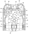
図5と図8に示すように、前後2列の絞り通路部45の下端開口部の直下に隣接してそれぞれ設けられた前後2列の供給口46のそれぞれの両側部には、回転体82に向けて球Bを案内する球案内位置と、回転体82の外周面からから遠ざかる退避位置とに変位可能な前後各一対の可動案内部材60がそれぞれ装着されている。この実施の形態において、図8に示すように、前後各一対の可動案内部材60は、その一端部寄りにおいて軸61を中心としてそれぞれ個別に回動可能に、第1、第2通路構成部材33、34の基板部の所定位置にそれぞれ取り付けられている。そして、一対の可動案内部材60の他端側(相対する先端側)には、球Bの直径寸法よりも1.05倍程度で僅かに大きい間隔寸法W4を隔てて対向し球Bを回転体82に向けて案内するための案内部62が形成されている。また、一対の可動案内部材60の案内部62は、軸61と略同一中心をなす円弧面に形成されている。
【0022】
また、図8に示すように、前後各一対の可動案内部材60は、その所定位置に形成されたストッパ部64と、第1、第2通路構成部材33、34の基板部の所定位置にそれぞれ形成された規制孔65によってその回動範囲(回動角度)が規制されている。すなわち、前後各一対の可動案内部材60は、規制孔65の一側縁にストッパ部64が当接する球案内位置と、規制孔65の他側縁にストッパ部64が当接する退避位置との範囲において軸61を中心としてそれぞれ回動可能となっている。また、前後各一対の可動案内部材60は、弾性体66の弾発力によって球案内位置に配置保持され、所定値以上の荷重が作用したときには、弾性体66を弾性変形させながら前記退避位置に向けて変位するように構成されている。
【0023】
この実施の形態において、一対の可動案内部材60の所定位置には、その各ストッパ部64の近傍においてバネ掛け部がそれぞれ形成され、これら両バネ掛け部に跨ってコイルスプリングよりなる弾性体66の両端部が掛け止めされて張設されている。そして、一対の可動案内部材60は、共通の弾性体66の弾発力をそれぞれ受けて球案内位置に配置保持される一方、一対の可動案内部材60のうち、片側の可動案内部材60に対してのみ所定値以上の荷重が作用したときでも、その片側の可動案内部材60のみが弾性体66の弾発力に抗して、退避位置に向けて変位するように構成されている。また、一対の可動案内部材60の下側面には、球Bを押し下げる押下面63が略湾曲状に形成されている。
【0024】
図2、図8及び図11に示すように、前後2列の供給口46の直下に位置する回転体配設部には、各供給口46の球Bを受けて払い出す前後2列のスプロケット部83、87を有する回転体82が正逆方向に回転可能に配設されている。そして、回転体82の一方向(図8に向かって反時計回り方向)の回転動作によって遊技盤の各種入賞口に入ったときの賞球数に対応する数の球Bを払い出すとともに、反対方向の回転動作によって、貸球機(図示しない)から送られる貸球数に対応する数の球Bを払い出すようになっている。すなわち、図2と図11に示すように、回転体82には、前側の供給口46に対応するスプロケット部83と、後側の供給口46に対応するスプロケット部87とを同一中心線上に一体状に備えている。また、前側のスプロケット部83の前端面中心部には、第1通路構成部材33の基板部の所定位置に設けられたボス部に装着された軸95が挿通され、後側のスプロケット部87の後端面中心部に突設された連結部には、払出用モータ80の出力軸81がトルク伝達可能に嵌挿される連結孔が形成されている。そして、回転体82は払出用モータ80を駆動源として正逆方向に回転駆動されるようになっている。
【0025】
また、この実施の形態において、図11に示すように、前側のスプロケット部83の外周には、複数(例えば3個)の凹円弧の球受部84が所定の間隔(例えば、3個の場合120度間隔)を保って凹設されている。そして、各球受部84は、その両肩部のうち、一方を第1払出部85とし、他方を第2払出部86としている。また、後側のスプロケット部87の外周には、前側のスプロケット部83の球受部84に対し半ピッチ分(例えば、3個の場合60度)だけそれぞれ位相して複数(例えば3個)の凹円弧の球受部88が凹設され、各球受部88の両肩部のうち、一方を第1払出部89とし、他方を第2払出部90としている。
【0026】
また、この実施の形態において、図2に示すように、払出用モータ80の出力軸81の外周には、被検出部材100がトルク伝達可能に取り付けられており、この被検出部材100の外周面に形成されたリング部101には、前後2列の両スプロケット部83の球受け部84、88の合計の数に対応する数(例えば6個)のスリットあるいは孔等よりなる被検出部がそれぞれ設けられ、これら被検出部を検出する払出数検出器105が第3通路構成部材35の基板部の後側部に装着されている。そして、賞球、あるいは貸球の払出個数に対応して被検出部材100の被検出部が払出数検出器105によって検出されるようになっている。
【0027】
また、払出用モータ80は、ユニットケース32の後側に設置されたモータ用保護ケース110内に収納された状態でそのユニットケース32に固定されている。そして、払出用モータ80は遊技機1の所定位置に配設された主制御基板または枠制御基板(共に図示しない)から送られる賞球払出信号に基づいて回転制御されるとともに、遊技機1の片側に設置された貸球機(図示しない)から送られる貸球払出信号に基づいて回転制御されるようになっている。また、この実施の形態において、図2と図4に示すように、第3通路構成部材35の後面の略下半部の四周縁に突設された台枠部に保護ケース110が装着されている。この保護ケース110は、払出用モータ80がビス等によって固定されるベース部111と、そのベース部111に開閉可能に装着されたカバー体120とを備えている。
【0028】
また、ベース部111は、アルミ、銅、ステンレス、鉄等の吸熱並びに放熱性に優れた金属板よりなり、払出用モータ80を固定する取付板部112と、その取付板部112の両側部から後方に向けて略直角状に折り曲げられて形成された側板部113とを備えている。そして、ベース部111は、その取付板部112の所定位置において、ビス等によってユニットケース32の後側に取り付けられ、その取付板部112の後面の取付面に払出用モータ80がビス等によって固定されている。なお、払出用モータ80の出力軸81は、取付板部112を貫通して回転体82の後側のスプロケット部87の連結部にトルク伝達可能に嵌挿されるようになっている(図2参照)。
【0029】
また、この実施の形態において、図2と図8に示すように、前後2列の賞球用通路72の所定位置には、その通路に払い出された球Bを検出する賞球用検出器75が配設され、前後2列の貸球用通路73の所定位置には、その通路に払い出された球Bを検出する貸球用検出器76が配設されている。賞球用検出器75による球Bの検出信号は、主制御基板と枠制御基板にそれぞれ送られ、貸球用検出器76による球Bの検出信号は、球貸機と枠制御基板にそれぞれ送られるようになっている。そして、賞球数あるいは貸球数に対応する数の球Bに対し、賞球用検出器75あるいは貸球用検出器76において検出される検出個数が不足している場合(例えば、球タンク11、タンクレール12等において球Bの供給不良が発生したとき球Bの払い出し個数に不足が生じる)、その不足に相当する信号が払出用モータ80に送られ、これによって、回転体82が不足数に対応する分だけ回転し、所要とする数の球Bが不足なく正確に払い出されるようになっている。また、賞球用通路72と貸球用通路73とはその各下流に連通して設けられた本体側払出通路14において合流する(図1参照)。
【0030】
また、この実施の形態において、図6に示すように、ユニットケース32内には、前後2列の球通路40の球Bの有無を検出するための検出器130が設けられている。この検出器130は、板バネ状の作動板131を有し、その作動板131が検出保護片135によって保護された状態で前後2列の球通路40に臨んでいる。すなわち、前後2列の球通路40の通路壁41の上部には切り欠き状の開口孔が形成され、その開口孔に臨んで検出保護片135がその上部の軸136を支点として揺動可能に組み付けられている。そして、球通路40の上部に球Bがあるときにはその球Bの荷重を受けて検出保護片135が通路壁41の内壁面と略同一面をなす後退位置に配置され、これによって作動板131が後退されることで球Bの存在が検出される。また、球通路40の上部に球Bが存在しないときには、作動板131が球通路40内に向けて変位し、これによって球通路40の上部に球Bが存在しないことが検出されるようになっている。その際、作動板131の変位によって検出保護片135が軸136を中心として球通路40内に向けて突出する。
【0031】
この実施の形態に係る遊技機1は上述したように構成される。したがって、遊技に先だって、あるいは、遊技の際において、球タンク11からタンクレール12の前後2列の球送り通路13を経て、その球送出部から送られる球Bは、前後2列の球通路40の補充口からその球通路40の上通路部43、幅広通路部44及び絞り通路部45を順に流れ、絞り通路部45下端の供給口46を経て回転体82の前後2列のスプロケット部83、87上にそれぞれ流れる。そして、前後2列のスプロケット部83、87において、例えば、前側のスプロケット部83の外周面と、後側のスプロケット部87の球受部88上に球Bがそれぞれ供給される(図8参照)。
【0032】
ここで、遊技機1の前側の所定位置に配設された球貸しスイッチ(図示しない)が作動されると、その信号が枠制御基板に送られる。また、前記球貸しスイッチの作動に基づく信号が遊技機1の片側に設置された貸球機(図示しない)に送られ、その貸球機から発せられる貸球数に対応する数の信号が枠制御基板に送られる。これに基づいて枠制御基板から発せられる払出信号によって払出用モータ80が回転制御される。すると、払出用モータ80によって、回転体82が一方向(例えば、図9に向かって時計回り方向)にかつ貸球数に対応する回転数あるいは回転角度だけ回転する。回転体82の所定方向の回転によって、その前後2列のスプロケット部83、87の各球受部84、88に球Bが順次に受けられ、引き続いて球受部84、88の回転方向後側の第1払出部85、89に押されかつ球Bの自重も加わって前後2列の貸球用通路73にそれぞれ払い出される。前後2列の貸球用通路73にそれぞれ払い出された球Bは、前後2列の本体側払出通路14にそれぞれ流れた後、前後2列の本体側払出通路14を経て上皿用球通路16に流れ上皿に払い出される。
【0033】
また、遊技の際、遊技盤11の遊技領域に発射された球Bが入賞口に流入し検出器によって検出されると、その信号が主制御基板に送られる。そして、主制御基板から発せられる賞球数に対応する数の信号が枠制御基板に送られ、これに基づいて枠制御基板から発せられる払出信号によって払出用モータ80が回転制御される。すると、払出用モータ80によって、回転体82が反対方向(図9に向かって反時計回り方向)にかつ賞球数に対応する回転角度だけ回転する。回転体82の反対方向の回転によって、その前後2列のスプロケット部83、87の各球受部84、88に球Bが順次に受けられ、引き続いて球受部84、88の回転方向後側の第2払出部86、90に押されかつ球Bの自重も加わって前後2列の賞球用通路72にそれぞれ払い出される。前後2列の賞球用通路72に払い出された球Bは、前後2列の本体側払出通路14を経て上皿用球通路16に流れ上皿6に払い出される。
【0034】
前記したように、球通路40の直下に位置する供給口46に供給された球Bを、回転体82の回転動作によって、その前後2列のスプロケット部83、87の各球受部84、88に受け、これら球Bを前後2列の賞球用通路72あるいは貸球用通路73に払い出す際、供給口46の可動案内部材60と回転体82のスプロケット部83、87の外周面との間に球Bが不測に噛み込もうとすることがある。球Bが噛み込もうとする所定値以上の荷重が可動案内部材60に作用すると、可動案内部材60は、弾性体66の弾発力に抗してかつ弾性体66を弾性変形させながら、その案内部62が回転体82のスプロケット部83(又は87)の外周面から遠ざかる退避位置に向けて軸61を中心として回動し変位する(図10参照)。このため、供給口46の可動案内部材60と回転体82のスプロケット部83、87の外周面との間に球Bが不測に噛み込んで回転体82の回転が停止する、という球噛みによる不具合の発生を防止することができる。
【0035】
また、この実施の形態においては、供給口46の両側部に一対の可動案内部材60が球案内位置と、退避位置とに変位可能に設けられ、一対の可動案内部材60の案内部62の間隔寸法W4が球Bの直径寸法よりも1.05倍程度で僅かに大きい間隔寸法に設定されいる。このため、図8に示すように、供給口46に供給された球Bを一対の可動案内部材60の案内部62によって回転体82に向けて良好に案内することができる。また、この実施の形態においては、一対の可動案内部材60の案内部62が、軸61と略同一中心をなす円弧面に形成されている。このため、球案内位置にある可動案内部材60が、軸61を中心として退避位置に向けて回動する際、その案内部62が供給口46の球Bに干渉して可動案内部材60の退避動作が妨げられる不具合が防止される。
【0036】
また、この実施の形態においては、一対の可動案内部材60のバネ掛け部に跨って1本のコイルスプリングよりなる弾性体66の両端部が掛け止めされて張設されている。そして、一対の可動案内部材60は、共通の弾性体66の弾発力をそれぞれ受けて球案内位置に配置保持されるようになっている。このため、一対の可動案内部材60に対しそれぞれ別個の弾性体を組み付けて弾発する必要性を解消することができ、弾性体66を共通化した分だけ部品点数や組付工数を軽減してコスト低減を図ることができる。
【0037】
なお、この発明は前記実施の形態に限定するものではない。例えば、前記実施の形態においては、球払出装置30が一つのユニット化された球払出装置ユニット31によって構成され、機構板10のユニット装着部に対し着脱可能に装着される場合を例示したが、機構板10の所定位置に球払出装置30の各通路の通路壁を形成したり、各種検出器や通路切換部材、可動案内部材60、回転体82、払出用モータ80等をそれぞれ組み付けて球払出装置30を構成することも可能である。また、前記実施の形態において球払出装置30として、払出用モータ80を駆動源としかつ前後2列のスプロケット部83、87を備えた回転体82を主体として構成される場合を例示したが、球Bを送出する機能を有する回転体を備えた球送出装置であればこの発明を実施することができる。また、球払出装置30の球通路40等は、前後2列以上の複列に設けてもよく、また単列に設けてもよい。
【0038】
【発明の効果】
以上述べたように、この発明によれば、回転体の回転動作によって球を払い出す際、球通路の供給口の可動案内部材と回転体の外周面との間に球が不測に噛み込もうとする際、可動案内部材が退避位置に向けて変位するため、供給口の可動案内部材と回転体の外周面との間に球が不測に噛み込んで回転体の回転が停止する、という球噛みによる不具合の発生を防止することができる。
【図面の簡単な説明】
【図1】 この発明の実施の形態に係る遊技機としてのパチンコ機を一部破断して示す背面図である。
【図2】 同じく球払出装置ユニットを示す縦断面図である。
【図3】 同じく球払出装置ユニットを示す背面図である。
【図4】 同じく球払出装置ユニットを示す正面図である。
【図5】 同じく球払出装置ユニットの第1通路構成部材(又は第2通路構成部材)を示す正面図である。
【図6】 同じく球払出装置ユニットの第1通路構成部材(又は第2通路構成部材)の上部を拡大して示す正面図である。
【図7】 同じく球払出装置ユニットの第1通路構成部材(又は第2通路構成部材)の中間部を拡大して示す正面図である。
【図8】 同じく球払出装置ユニットの第1通路構成部材(又は第2通路構成部材)の下部に一対の可動案内部材と回転体が配設された状態を拡大して示す正面図である。
【図9】 同じく球通路から供給口に供給された球が回転体の回転によって賞球用通路に払い出される状態を示す説明図である。
【図10】 同じく可動案内部材が退避位置に向けて変位される状態を示す説明図である。
【図11】 同じく回転体を拡大して示す正面図である。
【符号の説明】
1 遊技機
10 機構板
30 球払出装置
31 球払出装置ユニット
32 ユニットケース
33 第1通路構成部材
34 第2通路構成部材
35 第3通路構成部材
40 球通路
46 供給口
60 可動案内部材
62 案内部
66 弾性体
82 回転体
83、87 スプロケット部
84、88 球受部
[0001]
BACKGROUND OF THE INVENTION
The present invention relates to a gaming machine that uses a ball (pachinko ball) to play a game, for example, a game machine called a ball ball gaming machine (mainly a pachinko machine), or a slot machine game that uses a ball instead of a coin. It is related with the game machine which performs a game like this.
[0002]
[Prior art]
In a gaming machine that uses a ball (pachinko ball) to play a game, a number of balls corresponding to the number of winning or rented balls are placed in a predetermined position, for example, on the front side of the gaming machine via a payout passage. It is necessary to configure to pay out (upper plate or lower plate). For this reason, a ball payout device having a ball passage and a rotating body that receives the ball supplied from the supply port at the lower end of the ball passage and pays out the ball is disposed at a predetermined position of the gaming machine. It is like that. Moreover, it is common that a plurality of ball receiving portions for receiving a ball are formed in a sprocket shape provided at a predetermined angle on the outer peripheral surface of the rotating body of the ball dispensing device.
[0003]
[Problems to be solved by the invention]
By the way, if the sphere supplied from the supply port at the lower end of the sphere passage is received by the rotating body and the sphere is dispensed by the rotating operation of the rotating body, the sphere is formed between the supply port and the outer peripheral surface of the rotating body. There is a case in which a trouble due to so-called ball biting occurs in which the rotation of the rotating body stops unexpectedly. When such a ball bite occurs, a ball bite eliminating operation for removing the ball bitten between the supply port at the lower end of the ball passage and the outer peripheral surface of the rotating body is required, which is troublesome.
[0004]
In view of the above problems, an object of the present invention is to provide a gaming machine that can prevent a problem that a ball is accidentally bitten between a supply port of a ball passage and an outer peripheral surface of a rotating body.
[0005]
[Means for Solving the Problems]
In order to achieve the above object, a gaming machine according to a first aspect of the present invention has a configuration as described in claim 1 and is supplied from a ball passage and a supply port at a lower end of the ball passage. And a ball dispensing device having a rotating body that receives the ball and delivers the ball. In the rotating body, a plurality of sprocket parts and concave arc-shaped ball receiving parts are alternately arranged in the circumferential direction of rotation, and the center of rotation is located on a vertical center line passing through the supply port. And can be rotated in the forward and reverse directions by the dispensing motor. On both sides of the supply port , a guide part formed in a convex arcuate shape facing the gap toward the rotating body, with a gap dimension slightly larger than the diameter dimension of the sphere, and the guide part A pair of movable guide members having a pressing surface formed in a concave curved shape on the lower side continuous with the lower end of each of the first and second guide members , each of which is centered on an axis at a ball guide position and a retracted position where the guide part moves away from the rotating body. rotatably provided Rutotomoni elastic body astride between the pair of movable guide member Ru is disposed. The pair of movable guide members are always biased and held at the ball guide positions where the guide portions are opposed by the tensile force equivalent to the left and right of the elastic body, and one of the movable guide members is rotated along with the rotation of the rotating body. When a sphere is caught between the movable guide member and the outer peripheral surface of the sprocket portion and a load greater than a predetermined value is applied, the contacted sphere is in contact with the convex arc surface of the guide portion. contact between the front SL against the tension force of the elastic body and rotational displacements around the axis to the retracted position from the ball guide position, bitten and convex arcuate surface of the guide portion balls When there is no more, the elastic body is configured to be rotationally displaced about the axis from the retracted position to the ball guiding position so as to push down the ball caught by the concave curved surface of the pressing surface by the tensile force of the elastic body. It is.
[0006]
Therefore, the sphere supplied to the supply port at the lower end of the sphere passage is guided by the guide portion of the movable guide member and supplied to the rotating body. Then, the balls supplied to the rotating body are paid out by the rotating operation of the rotating body. When the ball is paid out by the rotation of the rotating body, the ball may try to bite unexpectedly between the movable guide member of the supply port and the outer peripheral surface of the rotating body. When a load of a predetermined value or more that the sphere tries to bite into acts on the movable guide member, the movable guide member is displaced toward the retracted position where the guide portion moves away from the outer peripheral surface of the rotating body while elastically deforming the elastic body. To do. For this reason, it is possible to prevent the occurrence of a malfunction due to the ball engagement, in which the sphere is accidentally engaged between the movable guide member of the supply port and the outer peripheral surface of the rotator, and the rotation of the rotator is stopped.
[0007]
[0008]
[0009]
[0010]
DETAILED DESCRIPTION OF THE INVENTION
Embodiments of the present invention will be described with reference to the drawings. In FIG. 1 showing a gaming machine (for example, a pachinko machine) that uses a ball to play a game from the rear, the gaming machine 1 is a square that is mounted on the front side of the outer frame 2 and the outer frame 2 so as to be opened and closed by a hinge function. The frame-shaped front frame 3 is mainly used. As is well known, an open / close door having a glass plate, an upper plate capable of storing a ball B (pachinko ball), a lower plate, a handle device for launching a ball, and the like are disposed on the front side of the front frame 3. On the rear surface of the front frame 3, a game board mounting frame is assembled in a fixed state at the periphery of the frame opening, and a game board (not shown) is detachably fitted into the frame of the game board mounting frame. The periphery of the rear surface of the game board is fixed in a state where it is pushed by a mechanism plate 10 (also called a back set plate, a back mechanism plate, etc.). In the game area on the front side of the game board, various winning devices, accessory devices, symbol display devices, gate openings and the like are appropriately arranged.
[0011]
A ball tank 11 in which the ball B is stored and a tank rail 12 connected to a lower portion near one end of the ball tank 11 are mounted on the upper rear surface of the mechanism plate 10. The tank rail 12 is formed with an inclined ball feed passage 13 that flows while the balls B are aligned in two front and rear rows from one side to the other side (left side to right side in FIG. 1). A downwardly inclined end 13 is a ball delivery unit. On one side of the rear surface of the mechanism plate 10 (on the right side in FIG. 1), a unit mounting portion is provided adjacent to the ball delivery portion of the tank rail 12, and the unit mounting portion constitutes a ball dispensing device 30. Two unit-shaped ball dispensing device units 31 are detachably mounted.
[0012]
Further, on the rear side of the mechanism plate 10, the downstream ends of the prize ball passage 72 and the ball rental passage 73 of the ball dispenser unit 31 are joined and paid out from the prize ball passage 72 and the ball rental passage 73. Two rows of main body side payout passages 14 are formed to guide the sphere B to a predetermined position. Further, an upper plate ball passage 16 for guiding the ball B to the upper plate is provided in the downstream portion of the main body side discharge passage 14. Further, an upper dish ball reservoir 17 is formed in the upper dish ball passage 16, and one side of the upper dish ball reservoir 17 has an upper dish ball B when the upper dish ball B is full. A lower plate ball passage 19 is formed to guide the ball B of the ball reservoir 17 to the lower plate. Further, on the rear side of the mechanism plate 10, the main body side discharge for discharging the ball B of the ball tank 11 and the tank rail 12 to the outside through the discharge passage 50 provided in a part of the ball dispensing device unit 31. A passage 21 is formed.
[0013]
As shown in FIGS. 2 to 5, the ball dispensing device unit 31 includes a unit case 32, a path switching member 52 assembled to the unit case 32, a movable guide member 60, a rotating body 82, a dispensing motor 80, various detections. Equipment. The unit case 32 is mainly composed of three parts: a first passage constituting member 33, a second passage constituting member 34, and a third passage constituting member 35, which are formed by injection molding of a synthetic resin, etc. and are detachably coupled by screws or the like. It is configured as. As shown in FIG. 2 and FIG. 5, the unit case 32 is divided into a front and rear two-row spherical passage 40 and a supply port 46 communicating with the lower end of the spherical passage 40. Has been.
[0014]
Further, in this embodiment, as shown in FIG. 5, discharge passages 50 are defined in the unit case 32 so as to be adjacent to one side of the front and rear two rows of ball passages 40. A passage switching member 52 is disposed at the upper boundary between the discharge passage 50 and the ball passage 40 so as to be switchable between a first position and a second position by an operation lock member 55. As shown in FIG. 5, when the passage switching member 52 is disposed and locked at the first position by the operation lock member 55, the sphere B sent from the sphere delivery portion of the tank rail 12 flows into the discharge passage 50. It flows only in the spherical passage 40. Further, as shown in FIG. 6, when the operation lock member 55 is operated upward to be unlocked, the flow pressure of the sphere B flowing from the sphere delivery portion of the tank rail 12 toward the upper portion of the sphere passage 40 is received. The passage switching member 52 rotates about the shaft 53 and is switched to the second position. Thereby, the sphere B flowing toward the upper part of the sphere passage 40 flows into the discharge passage 50. The operation lock member 55 is springed toward a lower lock position by a spring 58, and the lower end portion of the operation lock member 55 is detachably engaged with an engagement portion 54 formed at a predetermined position of the passage switching member 52. In combination, a lock portion 56 is formed to selectively lock the passage switching member 52 between the first position and the second position.
[0015]
As shown in FIG. 5, a rotating body disposing portion that communicates with the supply port 46 is formed in the lower part of the unit case 32, and the rotating body disposing portion receives a sphere B and is sprocket-shaped. A rotating body 82 is disposed so as to be rotatable in forward and reverse directions. In the lower part of the unit case 32, a prize ball passage 72 is formed on one side (left side in FIG. 5) of the outer peripheral surface of the rotating body 82, and a ball rental passage 73 is formed in two rows in the front and rear directions. Has been.
[0016]
That is, as shown in FIGS. 2 and 5, between the first passage constituting member 33 and the second passage constituting member 34, the substrate portion of the first passage constituting member 33 and the substrate portion of the second passage constituting member 34 are disposed. Accordingly, the front and rear walls of the front ball passage 40, the front supply port 46, the front prize ball passage 72, the front ball rental passage 73, and the front discharge passage 50 are formed. Further, the front side wall of the rotating body disposing portion is formed by the substrate portion of the first passage constituting member 33, and the second passage constituting member 34 is formed with a hole through which the rotating body 82 is inserted. Further, at least one of the substrate portion of the first passage constituting member 33 and the substrate portion of the second passage constituting member 34 is a passage in which a front ball passage 40 and a front discharge passage 50 are adjacently formed. Walls 41, 42, 51 are formed, respectively, and outer walls 48 of the front prize ball passage 72 and the front ball rental passage 73 are formed. Further, at least one of the substrate portion of the first passage constituting member 33 and the substrate portion of the second passage constituting member 34 is adjacent to the lower side of the rotating body 82 and the front prize ball passage 72 and the front rental portion. A branch wall 59 that partitions the ball passage 73 is formed.
[0017]
Further, between the second passage constituting member 34 and the third passage constituting member 35, the rear side ball is formed by the substrate portion of the second passage constituting member 34 and the substrate portion of the third passage constituting member 35 in substantially the same manner. The front and rear walls of the passage 40, the rear supply port 46, the rear prize ball passage 72, the rear ball rental passage 73, and the rear discharge passage 50 are respectively formed, and a third passage Rear walls 48 and 49 of the rotating body disposing portion are formed by the substrate portion of the component member 35. In addition, at least one of the substrate portion of the second passage constituting member 34 and the substrate portion of the third passage constituting member 35 is formed with a rear spherical passage 40 and a rear discharge passage 50 adjacent to each other. Passage walls 41, 42, 51 are formed, respectively, and outer walls of the rear prize ball passage 72 and the rear ball rental passage 73 are formed. Further, at least one of the substrate portion of the second passage constituting member 34 and the substrate portion of the third passage constituting member 35 is adjacent to the lower portion of the rotating body 82 and the rear prize ball passage 72 and the rear side. A branch wall 59 that divides the ball rental passage 73 is formed.
[0018]
As shown in FIG. 5 to FIG. 8, the ball passage 40 in the form of two longitudinal rows of longitudinal passages has a top end (upstream end) replenishment port that opens to the side of the upper end of the unit case 32, and a tank The rails 12 communicate with each other so as to face the ball feeding portions at the lower inclined end of the two rows of the ball feeding passages 13 on the rail 12. The lower end (downstream end) of the front and rear two rows of ball passages 40 faces the rotating body 82 through the supply port 46. Further, the spherical passage 40 has an upper passage portion 43, a wide passage portion 44, and a throttle passage portion 45 that are sequentially communicated from the upper part toward the lower part. Further, in a state where the sphere B is in contact with the upper passage portion 43, the wide passage portion 44 and the throttle passage portion 45, and each of the spheres B is in contact with the inner wall surface of either one of the passage walls 41, 42. They are arranged in a line in a substantially zigzag shape.
[0019]
In this embodiment, the upper passage portion 43 has an inverted L shape bent downward from a replenishing port that opens laterally (laterally), and the passage width W1 of the upper passage portion 43 is a spherical shape. It is formed about 1.2 times larger than the diameter dimension of B. The wide passage portion 44 formed continuously at the lower portion of the upper passage portion 43 has a substantially central portion with a maximum passage width W2 and is formed in a substantially curved shape close to a straight line. The diameter is about 1.8 times larger than the diameter of the sphere B (about 1.5 times in this embodiment). The passage width of the upper part of the wide passage part 44 is formed to be about 1.2 times larger than the diameter dimension of the sphere B so as not to cause a step between the lower part of the upper passage part 43. The passage width at the lower part of the wide passage part 44 is formed to be about 1.3 times larger than the diameter dimension of the sphere B so as not to cause a step between the upper part of the throttle passage part 45.
[0020]
The throttle passage 45 formed continuously below the wide passage 44 is bent in a substantially S shape within a range of lateral displacement that is substantially the same as the lateral displacement of the wide passage 44. has been gradually passage width toward the bottom from Rutotomoni top shape is formed is reduced. The passage width in the upper part of the throttle passage part 45 is formed to be about 1.3 times larger than the diameter dimension of the sphere B so as not to cause a step between the lower part of the wide passage part 44. The lower portion of the throttle passage 45 is substantially vertical, and the passage width W3 of the lower end opening is formed to be slightly larger than the diameter of the sphere B by about 1.05 times.
[0021]
As shown in FIG. 5 and FIG. 8, a rotating body 82 is provided on each side of each of the front and rear two rows of supply ports 46 provided immediately adjacent to the lower end openings of the front and rear two rows of throttle passages 45. A pair of front and rear movable guide members 60 that are displaceable to a ball guide position that guides the ball B toward the center and a retracted position that moves away from the outer peripheral surface of the rotating body 82 are mounted. In this embodiment, as shown in FIG. 8, each of the pair of front and rear movable guide members 60 is capable of being individually rotated around a shaft 61 near the one end thereof, so that the first and second passage constituting members 33 can be individually rotated. , 34 are respectively attached to predetermined positions of the substrate portion. Then, the other end side (opposite tip side) of the pair of movable guide members 60 is opposed to the sphere B with a slightly larger spacing dimension W4 about 1.05 times the diameter dimension of the sphere B. A guide portion 62 for guiding toward 82 is formed. Further, the guide portions 62 of the pair of movable guide members 60 are formed on arcuate surfaces that are substantially the same center as the shaft 61.
[0022]
Further, as shown in FIG. 8, the pair of front and rear movable guide members 60 are respectively disposed at predetermined positions of the stopper portion 64 formed at the predetermined position and the substrate portions of the first and second passage constituting members 33 and 34. The rotation range (rotation angle) is restricted by the formed restriction hole 65. That is, each of the pair of front and rear movable guide members 60 has a range between a ball guide position where the stopper portion 64 abuts on one side edge of the restriction hole 65 and a retracted position where the stopper portion 64 abuts the other side edge of the restriction hole 65. In FIG. 1, each of them can be rotated around a shaft 61. The pair of front and rear movable guide members 60 are arranged and held at the ball guide position by the elastic force of the elastic body 66. When a load of a predetermined value or more is applied, the elastic body 66 is elastically deformed to the retracted position. It is comprised so that it may displace toward.
[0023]
In this embodiment, a spring hook portion is formed in the vicinity of each stopper portion 64 at a predetermined position of the pair of movable guide members 60, and the elastic body 66 made of a coil spring straddles both the spring hook portions. Both ends are hooked and stretched. The pair of movable guide members 60 receives the elastic force of the common elastic body 66 and is disposed and held at the ball guide position, while the pair of movable guide members 60 is opposed to the movable guide member 60 on one side. Even when a load greater than or equal to a predetermined value is applied, only the movable guide member 60 on one side is configured to be displaced toward the retracted position against the elastic force of the elastic body 66. Further, on the lower side surfaces of the pair of movable guide members 60, a pressing surface 63 that presses down the sphere B is formed in a substantially curved shape.
[0024]
As shown in FIGS. 2, 8, and 11, the front and rear two rows of sprockets that receive and dispense the ball B of each supply port 46 are disposed in the rotating body disposition portion located immediately below the front and rear rows of supply ports 46. A rotating body 82 having portions 83 and 87 is disposed so as to be rotatable in forward and reverse directions. Then, by rotating the rotating body 82 in one direction (counterclockwise direction toward FIG. 8), the number of balls B corresponding to the number of winning balls when entering various winning holes of the game board is paid out and By rotating the direction, the number of balls B corresponding to the number of balls sent from a ball rental machine (not shown) is paid out. That is, as shown in FIGS. 2 and 11, the rotating body 82 is integrally formed with a sprocket portion 83 corresponding to the front supply port 46 and a sprocket portion 87 corresponding to the rear supply port 46 on the same center line. It has a shape. In addition, a shaft 95 attached to a boss provided at a predetermined position of the base plate portion of the first passage constituting member 33 is inserted into the center portion of the front end surface of the front sprocket portion 83, and the rear sprocket portion 87 A connecting hole projecting from the central portion of the rear end surface is formed with a connecting hole into which the output shaft 81 of the payout motor 80 is inserted so as to transmit torque. The rotating body 82 is rotationally driven in the forward and reverse directions using the payout motor 80 as a drive source.
[0025]
Further, in this embodiment, as shown in FIG. 11, a plurality of (for example, three) concave arc ball receiving portions 84 are provided on the outer periphery of the front sprocket portion 83 at a predetermined interval (for example, three). It is recessed with an interval of 120 degrees. Each of the ball receiving portions 84 has one of the shoulder portions as a first payout portion 85 and the other as a second payout portion 86. In addition, the outer periphery of the rear sprocket portion 87 has a plurality of (for example, three) phases in phase with the ball receiving portion 84 of the front sprocket portion 83 by a half pitch (for example, 60 degrees in the case of three). A concave arc-shaped ball receiving portion 88 is recessed, and one of the shoulder portions of each ball receiving portion 88 is a first payout portion 89 and the other is a second payout portion 90.
[0026]
Further, in this embodiment, as shown in FIG. 2, the detected member 100 is attached to the outer periphery of the output shaft 81 of the payout motor 80 so as to transmit torque, and the outer peripheral surface of the detected member 100 In the ring portion 101 formed in the above, there are detected portions each consisting of a number of (for example, six) slits or holes corresponding to the total number of the ball receiving portions 84 and 88 of the two sprocket portions 83 in the front and rear rows. A payout number detector 105 provided for detecting these detected portions is mounted on the rear side portion of the substrate portion of the third passage constituting member 35. The detected portion of the detected member 100 is detected by the payout number detector 105 in correspondence with the number of payouts of the winning ball or the rented ball.
[0027]
The payout motor 80 is fixed to the unit case 32 in a state of being housed in a motor protection case 110 installed on the rear side of the unit case 32. The payout motor 80 is rotationally controlled based on a prize ball payout signal sent from a main control board or a frame control board (both not shown) disposed at a predetermined position of the gaming machine 1, and the gaming machine 1 The rotation is controlled based on a lending payout signal sent from a lending machine (not shown) installed on one side. In this embodiment, as shown in FIGS. 2 and 4, a protective case 110 is mounted on a frame portion projecting from the four peripheral edges of the substantially lower half of the rear surface of the third passage constituting member 35. Yes. The protective case 110 includes a base portion 111 to which the payout motor 80 is fixed by a screw or the like, and a cover body 120 attached to the base portion 111 so as to be openable and closable.
[0028]
The base portion 111 is made of a metal plate excellent in heat absorption and heat dissipation, such as aluminum, copper, stainless steel, and iron. The base portion 111 is attached to a mounting plate portion 112 that fixes the payout motor 80, and from both sides of the mounting plate portion 112. And a side plate portion 113 formed by being bent at a substantially right angle toward the rear. The base portion 111 is attached to the rear side of the unit case 32 with screws or the like at a predetermined position of the attachment plate portion 112, and the payout motor 80 is fixed to the attachment surface on the rear surface of the attachment plate portion 112 with screws or the like. Has been. The output shaft 81 of the payout motor 80 is inserted into the connecting portion of the sprocket portion 87 on the rear side of the rotating body 82 through the mounting plate portion 112 (see FIG. 2). ).
[0029]
Further, in this embodiment, as shown in FIGS. 2 and 8, a prize ball detector for detecting a ball B paid out to the passages at predetermined positions of the two rows of prize ball paths 72 in the front and rear rows. 75 is disposed, and a ball rental detector 76 for detecting the sphere B paid out to the passage is disposed at a predetermined position of the two rows of the ball rental passages 73 in the front and rear. The detection signal of the ball B by the prize ball detector 75 is sent to the main control board and the frame control board, respectively, and the detection signal of the ball B by the ball rental detector 76 is sent to the ball rental machine and the frame control board, respectively. It is supposed to be. When the number of balls B corresponding to the number of winning balls or the number of balls lent is detected by the winning ball detector 75 or the ball rental detector 76 is insufficient (for example, the ball tank 11 When the supply failure of the ball B occurs in the tank rail 12 or the like, a shortage occurs in the number of balls B to be dispensed), and a signal corresponding to the shortage is sent to the dispensing motor 80. The required number of balls B are accurately paid out without a shortage. Further, the prize ball passage 72 and the ball rental passage 73 merge in the main body side payout passage 14 provided in communication with each downstream thereof (see FIG. 1).
[0030]
In this embodiment, as shown in FIG. 6, a detector 130 is provided in the unit case 32 for detecting the presence or absence of the spheres B in the two rows of the sphere passages 40. The detector 130 has a plate spring-like operating plate 131, and faces the two rows of ball passages 40 in the front and rear direction in a state where the operating plate 131 is protected by the detection protection piece 135. That is, a notch-shaped opening hole is formed in the upper part of the passage wall 41 of the front and rear two rows of the ball passages 40, and the detection protection piece 135 can swing about the opening shaft 136 facing the opening hole. It is assembled. When the ball B is above the ball passage 40, the detection protection piece 135 is placed in a retracted position that is substantially flush with the inner wall surface of the passage wall 41 under the load of the ball B. The presence of the sphere B is detected by moving backward. Further, when the sphere B is not present above the sphere passage 40, the operation plate 131 is displaced toward the inside of the sphere passage 40, whereby it is detected that the sphere B is not present above the sphere passage 40. ing. At this time, due to the displacement of the operation plate 131, the detection protection piece 135 protrudes into the spherical passage 40 around the shaft 136.
[0031]
The gaming machine 1 according to this embodiment is configured as described above. Accordingly, prior to the game or during the game, the ball B sent from the ball delivery section 13 through the ball feed passages 13 in the front and rear rows of the tank rail 12 from the ball tank 11 is sent to the ball passages 40 in the front and rear rows. From the replenishing port to the upper passage portion 43, the wide passage portion 44, and the throttle passage portion 45 of the ball passage 40 in this order, and through the supply port 46 at the lower end of the throttle passage portion 45, two rows of sprocket portions 83 in the front and rear of the rotating body 82, 87 flows respectively. Then, in the front and rear two rows of sprocket portions 83 and 87, for example, the sphere B is supplied onto the outer peripheral surface of the front sprocket portion 83 and the ball receiving portion 88 of the rear sprocket portion 87 (see FIG. 8). .
[0032]
Here, when a ball lending switch (not shown) disposed at a predetermined position on the front side of the gaming machine 1 is operated, the signal is sent to the frame control board. Further, a signal based on the operation of the ball lending switch is sent to a ball lending machine (not shown) installed on one side of the gaming machine 1, and a number of signals corresponding to the number of lending issued from the lending machine It is sent to the control board. Based on this, the payout motor 80 is rotationally controlled by a payout signal issued from the frame control board. Then, the payout motor 80 causes the rotating body 82 to rotate in one direction (for example, the clockwise direction toward FIG. 9) and by the number of rotations or the rotation angle corresponding to the number of rented balls. By rotation of the rotating body 82 in a predetermined direction, the balls B are sequentially received by the ball receiving portions 84 and 88 of the two front and rear rows of sprocket portions 83 and 87, and subsequently the rear side in the rotation direction of the ball receiving portions 84 and 88. Are pushed out by the first payout portions 85 and 89 and the weight of the ball B is added, and the balls are paid out into the front and rear two rows of ball rental paths 73. The balls B paid out to the front and rear two rows of the ball lending passages 73 respectively flow into the front and rear two rows of the main body side payout passages 14, and then pass through the front and rear two rows of the main body side payout passages 14. 16 is flowed to the upper plate.
[0033]
Further, when a game is played, when the ball B launched into the game area of the game board 11 flows into the winning opening and is detected by the detector, the signal is sent to the main control board. Then, a number of signals corresponding to the number of prize balls issued from the main control board are sent to the frame control board, and the payout motor 80 is rotationally controlled based on this signal by a payout signal issued from the frame control board. Then, the payout motor 80 rotates the rotating body 82 in the opposite direction (counterclockwise direction toward FIG. 9) and by the rotation angle corresponding to the number of prize balls. Due to the rotation of the rotating body 82 in the opposite direction, the balls B are successively received by the ball receiving portions 84 and 88 of the two front and rear rows of the sprocket portions 83 and 87, and subsequently the rear side in the rotation direction of the ball receiving portions 84 and 88. Are pushed out by the second payout portions 86 and 90 and the weight of the ball B is added, and the balls are paid out to the two front and rear award ball paths 72, respectively. The balls B paid out to the two front and rear rows of prize ball passages 72 flow to the upper plate ball passage 16 through the two main and front rows of main body side payout passages 14 and are discharged to the upper plate 6.
[0034]
As described above, the sphere B supplied to the supply port 46 located immediately below the sphere passage 40 is rotated by the rotating body 82 so that the sphere receiving portions 84, 88 of the sprocket portions 83, 87 in two rows before and after the sphere B are rotated. When these balls B are paid out to the two winning and award rows of winning ball passages 72 or the rental ball passages 73, the movable guide member 60 of the supply port 46 and the outer peripheral surfaces of the sprocket portions 83 and 87 of the rotating body 82 In the meantime, the ball B may try to bite unexpectedly. When a load of a predetermined value or more that the ball B tries to bite is applied to the movable guide member 60, the movable guide member 60 resists the elastic force of the elastic body 66 and elastically deforms the elastic body 66. The guide portion 62 rotates and displaces about the shaft 61 toward the retracted position away from the outer peripheral surface of the sprocket portion 83 (or 87) of the rotating body 82 (see FIG. 10). For this reason, a problem due to the ball biting that the ball B unexpectedly bites between the movable guide member 60 of the supply port 46 and the outer peripheral surfaces of the sprocket parts 83 and 87 of the rotary member 82 and the rotation of the rotary member 82 stops. Can be prevented.
[0035]
Further, in this embodiment, a pair of movable guide members 60 are provided on both sides of the supply port 46 so as to be displaceable between a ball guide position and a retracted position, and the distance between the guide portions 62 of the pair of movable guide members 60. The dimension W4 is set to about 1.05 times the diameter dimension of the sphere B and is set to a slightly larger interval dimension. For this reason, as shown in FIG. 8, the sphere B supplied to the supply port 46 can be favorably guided toward the rotating body 82 by the guide portions 62 of the pair of movable guide members 60. In this embodiment, the guide portions 62 of the pair of movable guide members 60 are formed on arcuate surfaces that are substantially the same center as the shaft 61. For this reason, when the movable guide member 60 at the ball guide position rotates around the shaft 61 toward the retracted position, the guide portion 62 interferes with the sphere B of the supply port 46 to retract the movable guide member 60. Problems that prevent operation are prevented.
[0036]
In this embodiment, both ends of the elastic body 66 made of one coil spring are hooked and stretched across the spring hooks of the pair of movable guide members 60. The pair of movable guide members 60 are arranged and held at the ball guide positions by receiving the elastic force of the common elastic body 66, respectively. For this reason, it is possible to eliminate the necessity of assembling and elasticizing separate elastic bodies for the pair of movable guide members 60, and to reduce the number of parts and the number of assembling steps as much as the elastic body 66 is shared. Reduction can be achieved.
[0037]
The present invention is not limited to the above embodiment. For example, in the above-described embodiment, the ball payout device 30 is configured by the single ball payout device unit 31 and is detachably mounted on the unit mounting portion of the mechanism plate 10. Forming a passage wall of each passage of the ball dispensing device 30 at a predetermined position of the mechanism plate 10 or assembling various detectors, passage switching members, a movable guide member 60, a rotating body 82, a dispensing motor 80, etc. It is also possible to configure the device 30. Further, in the above-described embodiment, the ball dispensing device 30 is exemplified by the case where the dispensing motor 80 is configured mainly by the rotating body 82 having the dispensing motor 80 as a drive source and the two front and rear sprocket portions 83 and 87. The present invention can be implemented as long as it is a ball delivery device including a rotating body having a function of delivering B. Further, the ball passages 40 and the like of the ball dispensing device 30 may be provided in two or more rows in front and rear, or may be provided in a single row.
[0038]
【The invention's effect】
As described above, according to the present invention, when the ball is paid out by the rotating operation of the rotating body, the ball unexpectedly bites between the movable guide member of the supply port of the ball passage and the outer peripheral surface of the rotating body. In this case, since the movable guide member is displaced toward the retracted position, the ball unexpectedly bites between the movable guide member of the supply port and the outer peripheral surface of the rotary body, and the rotation of the rotary body stops. Occurrence of problems due to biting can be prevented.
[Brief description of the drawings]
FIG. 1 is a rear view partially showing a pachinko machine as a gaming machine according to an embodiment of the present invention.
FIG. 2 is a longitudinal sectional view showing the same ball dispensing device unit.
FIG. 3 is a rear view of the same ball dispensing device unit.
FIG. 4 is a front view of the same ball dispensing device unit.
FIG. 5 is a front view showing a first passage constituent member (or a second passage constituent member) of the ball dispensing device unit.
FIG. 6 is an enlarged front view of the upper part of the first passage constituent member (or the second passage constituent member) of the ball dispensing device unit.
FIG. 7 is an enlarged front view of the intermediate portion of the first passage constituent member (or the second passage constituent member) of the ball dispensing device unit.
FIG. 8 is an enlarged front view showing a state in which a pair of movable guide members and a rotating body are disposed below a first passage constituent member (or a second passage constituent member) of the ball dispensing device unit.
FIG. 9 is an explanatory view showing a state in which a ball supplied from the ball passage to the supply port is paid out to a prize ball passage by rotation of a rotating body.
FIG. 10 is an explanatory view showing a state where the movable guide member is similarly displaced toward the retracted position.
FIG. 11 is an enlarged front view of the rotating body.
[Explanation of symbols]
DESCRIPTION OF SYMBOLS 1 Game machine 10 Mechanism board 30 Sphere delivery apparatus 31 Sphere delivery apparatus unit 32 Unit case 33 1st channel | path component member 34 2nd channel | path component member 35 3rd channel | path component member 40 Ball channel | path 46 Supply port 60 Movable guide member 62 Guide part 66 Elastic body 82 Rotating body 83, 87 Sprocket part 84, 88 Ball receiving part

Claims (1)

球通路と、その球通路の下端の供給口から供給された球を受けてその球を払い出す回転体と、を有する球払出装置を備えた遊技機であって、
前記回転体は、複数個のスプロケット部と、凹円弧状の球受部と、が回転円周方向に交互に配置形成されると共に、その回転中心が前記供給口を通る縦中心線上に位置して払出用モータにより正逆方向に回転可能とされ、
前記供給口の両側部には、球の直径寸法よりも僅かに大きい間隔寸法を隔てて対向し前記回転体に向けて球を案内する凸円弧面状に形成される案内部と、該案内部の下端部と連続する下側面に凹湾曲状に形成される押下面と、を有する一対の可動案内部材が、球案内位置と前記案内部が回転体から遠ざかる退避位置とに軸を中心に個々に回動可能に設けられると共に、前記一対の可動案内部材の間に跨って弾性体が配設され、
前記一対の可動案内部材は、常には前記弾性体の左右同等な引張力によって前記案内部が対向する前記案内位置に付勢保持されるとともに、前記回転体の回転に伴っていずれか一方の可動案内部材と前記スプロケット部の外周面との間に球が噛み込まれて所定値以上の荷重が作用したときにはその噛み込まれた球と前記案内部の凸円弧面との当接により前記弾性体の引張力に抗して前記球案内位置から前記退避位置へと前記軸を中心にして回動変位し、前記案内部の凸円弧面と噛み込まれた球との当接状態がなくなったときには前記弾性体の引張力により前記押下面の凹湾曲面によって噛み込まれた球を押し下げるように前記退避位置から前記球案内位置へと前記軸を中心にして回動変位することを特徴とする遊技機。
A gaming machine comprising a ball payout device having a ball passage and a rotating body that receives the ball supplied from a supply port at the lower end of the ball passage and pays out the ball,
In the rotating body, a plurality of sprocket parts and concave arc-shaped ball receiving parts are alternately arranged in the circumferential direction of rotation, and the center of rotation is located on a vertical center line passing through the supply port. And can be rotated in the forward and reverse directions by the dispensing motor.
On both sides of the supply port , a guide part formed in a convex arcuate shape facing the gap toward the rotating body, with a gap dimension slightly larger than the diameter dimension of the sphere, and the guide part A pair of movable guide members having a pressing surface formed in a concave curved shape on the lower side continuous with the lower end of each of the first and second guide members , each of which is centered on an axis at a ball guide position and a retracted position where the guide part moves away from the rotating body. rotatably provided Rutotomoni elastic body astride between the pair of movable guide member is disposed,
The pair of movable guide members are always biased and held at the ball guide positions where the guide portions face each other by a tensile force equivalent to the left and right of the elastic body, and one of the movable guide members is rotated along with the rotation of the rotating body. When a sphere is caught between the movable guide member and the outer peripheral surface of the sprocket portion and a load greater than a predetermined value is applied, the contacted sphere is in contact with the convex arc surface of the guide portion. contact between the front SL against the tension force of the elastic body and rotational displacements around the axis to the retracted position from the ball guide position, bitten and convex arcuate surface of the guide portion balls When there is no longer any movement, the elastic body is rotationally displaced about the axis from the retracted position to the ball guiding position so as to push down the ball bitten by the concave curved surface of the pressing surface by the tensile force of the elastic body. A featured gaming machine.
JP2002186782A 2002-02-12 2002-06-26 Game machine Expired - Fee Related JP4300552B2 (en)

Priority Applications (1)

Application Number Priority Date Filing Date Title
JP2002186782A JP4300552B2 (en) 2002-02-12 2002-06-26 Game machine

Applications Claiming Priority (3)

Application Number Priority Date Filing Date Title
JP2002034284 2002-02-12
JP2002-34284 2002-02-12
JP2002186782A JP4300552B2 (en) 2002-02-12 2002-06-26 Game machine

Publications (2)

Publication Number Publication Date
JP2003305245A JP2003305245A (en) 2003-10-28
JP4300552B2 true JP4300552B2 (en) 2009-07-22

Family

ID=29405079

Family Applications (1)

Application Number Title Priority Date Filing Date
JP2002186782A Expired - Fee Related JP4300552B2 (en) 2002-02-12 2002-06-26 Game machine

Country Status (1)

Country Link
JP (1) JP4300552B2 (en)

Families Citing this family (4)

* Cited by examiner, † Cited by third party
Publication number Priority date Publication date Assignee Title
JP5070390B2 (en) * 2003-11-14 2012-11-14 株式会社大一商会 Game machine
JP4481044B2 (en) * 2004-03-12 2010-06-16 株式会社Mrd Ball dispensing unit
JP4890979B2 (en) * 2006-07-10 2012-03-07 株式会社平和 Game machine
JP5004310B2 (en) * 2009-06-30 2012-08-22 株式会社サンセイアールアンドディ Game machine

Also Published As

Publication number Publication date
JP2003305245A (en) 2003-10-28

Similar Documents

Publication Publication Date Title
JP4300552B2 (en) Game machine
JP4214545B2 (en) Game machine
JP4300551B2 (en) Game machine
JP3599319B2 (en) Pachinko ball dispensing device
JP2003236184A (en) Gaming machine
JP4677830B2 (en) Ball dispensing device and game machine
JP4322817B2 (en) Hopper device
JP2911805B2 (en) Ball stop structure of transfer gutter in pachinko machine
JP2849694B2 (en) Pachinko game machine
JP6416026B2 (en) GAME BALL DISTRIBUTION DEVICE AND GAME MACHINE WITH THE SAME
JP4346046B2 (en) Bullet ball machine
JP4491250B2 (en) Game machine
JP4046922B2 (en) Game machine
JP3990756B2 (en) Ball stop structure of transfer rod in pachinko machine
JP4385446B2 (en) Pachinko machine
JP3877338B2 (en) Pachinko ball dispensing device
JP4188332B2 (en) Pachinko machine
JP3990622B2 (en) Ball dispensing device and game machine
JP4566343B2 (en) Ball passage switching device for a ball game machine
JP6627852B2 (en) Gaming machine
JP4576575B2 (en) Game machine
JP4400848B2 (en) Ball passage switching device for a ball game machine
JPH0634850B2 (en) Ball hitting device for pachinko machines
JP2006181047A (en) Game machine
JP5327909B2 (en) Unitized ball payout mechanism for pachinko machines

Legal Events

Date Code Title Description
A621 Written request for application examination

Free format text: JAPANESE INTERMEDIATE CODE: A621

Effective date: 20050624

RD05 Notification of revocation of power of attorney

Free format text: JAPANESE INTERMEDIATE CODE: A7425

Effective date: 20080709

A131 Notification of reasons for refusal

Free format text: JAPANESE INTERMEDIATE CODE: A131

Effective date: 20081125

A521 Written amendment

Free format text: JAPANESE INTERMEDIATE CODE: A523

Effective date: 20090122

RD02 Notification of acceptance of power of attorney

Free format text: JAPANESE INTERMEDIATE CODE: A7422

Effective date: 20090122

A521 Written amendment

Free format text: JAPANESE INTERMEDIATE CODE: A821

Effective date: 20090122

TRDD Decision of grant or rejection written
A01 Written decision to grant a patent or to grant a registration (utility model)

Free format text: JAPANESE INTERMEDIATE CODE: A01

Effective date: 20090318

A01 Written decision to grant a patent or to grant a registration (utility model)

Free format text: JAPANESE INTERMEDIATE CODE: A01

A61 First payment of annual fees (during grant procedure)

Free format text: JAPANESE INTERMEDIATE CODE: A61

Effective date: 20090410

FPAY Renewal fee payment (event date is renewal date of database)

Free format text: PAYMENT UNTIL: 20120501

Year of fee payment: 3

R150 Certificate of patent or registration of utility model

Free format text: JAPANESE INTERMEDIATE CODE: R150

FPAY Renewal fee payment (event date is renewal date of database)

Free format text: PAYMENT UNTIL: 20120501

Year of fee payment: 3

S531 Written request for registration of change of domicile

Free format text: JAPANESE INTERMEDIATE CODE: R313531

R350 Written notification of registration of transfer

Free format text: JAPANESE INTERMEDIATE CODE: R350

FPAY Renewal fee payment (event date is renewal date of database)

Free format text: PAYMENT UNTIL: 20150501

Year of fee payment: 6

R250 Receipt of annual fees

Free format text: JAPANESE INTERMEDIATE CODE: R250

R250 Receipt of annual fees

Free format text: JAPANESE INTERMEDIATE CODE: R250

R250 Receipt of annual fees

Free format text: JAPANESE INTERMEDIATE CODE: R250

LAPS Cancellation because of no payment of annual fees