JP4296670B2 - Portable communication device - Google Patents
Portable communication device Download PDFInfo
- Publication number
- JP4296670B2 JP4296670B2 JP2000024148A JP2000024148A JP4296670B2 JP 4296670 B2 JP4296670 B2 JP 4296670B2 JP 2000024148 A JP2000024148 A JP 2000024148A JP 2000024148 A JP2000024148 A JP 2000024148A JP 4296670 B2 JP4296670 B2 JP 4296670B2
- Authority
- JP
- Japan
- Prior art keywords
- ring
- case
- communication device
- frame
- portable communication
- Prior art date
- Legal status (The legal status is an assumption and is not a legal conclusion. Google has not performed a legal analysis and makes no representation as to the accuracy of the status listed.)
- Expired - Fee Related
Links
Images


Description
【0001】
【発明の属する技術分野】
本発明は、携帯通信機、特に携帯通信機の表示部保護構造に関する。
【0002】
【従来の技術】
携帯電話機等の携帯通信機においては、機器ケースに備えられる表示部が保護ガラスで覆われている。
従来、携帯通信機は、表示部の保護ガラスの表面が機器ケースの表面と略面一となっていた。
【0003】
【発明が解決しようとする課題】
しかし、最近の携帯通信機は、表示部が大きくなってきており、従来と同様にケース表面と面一構造の場合、表示部の保護ガラスが割れたり、疵が付いたりする危険性が高くなってきている。
【0004】
本発明の課題は、表示部保護ガラスを備える携帯通信機において、表示部の保護ガラスを保護することである。
【0005】
【課題を解決するための手段】
以上の課題を解決するため、請求項1記載の発明は、例えば、図1に示すように、ケース本体2に表示部33を備える携帯型の携帯通信機1において、前記表示部33の上面には、周縁部に剛性を有するとともに装飾機能を有するリング形状の枠部材12が取り付けられるとともに中央部が周辺部よりも突出する曲面形状の保護ガラス11が設けられ、前記保護ガラス11の周囲は、前記ケース本体2の表面及び前記保護ガラス11の曲面形状部よりも突出するリング枠状の緩衝部材13により、前記枠部材の内周面側が装飾部として露出する状態で囲まれており、更に前記ケース本体2の上部及び下部には、上部緩衝部材5及び下部緩衝部材6が設けられていることを特徴とする。
請求項1記載の発明によれば、表示部保護ガラスの周縁部に取り付けられた剛性を有するリング形状の枠部材によって表示部保護ガラスの強度を向上できるとともに、表示部保護ガラスの周囲に設けられた、表示部保護ガラスの表面及びケース本体の表面よりも突出するリング枠状の緩衝部材によって、表示部の保護ガラスを保護でき、また、このリング枠状の緩衝部材及び内周面側が露出する前記枠部材によって、デザイン上の斬新感も付与できる。
さらにケースの上部及び下部の緩衝部材によって、上下方向からの衝撃を吸収し、保護ガラスを保護できる。
ここで、携帯通信機としては、携帯電話機(PHSを含む)が代表的であるが、他の携帯端末機等の無線送受信機であっても良い。表示部の保護ガラスとしては、アクリル製の人工ガラスが挙げられるが、天然ガラスであっても良く、さらに、表面がハードコート処理されていることが望ましい。また、実施の形態では保護ガラスを円形とし、またそれに伴いリング形状の枠部材も円形のものとしたが、これらは楕円形や多角形のものでも良く、どのような形状のものでも良い。緩衝部材としては、軟質樹脂製のものの他、硬質樹脂製のものでも良い。
【0006】
請求項2記載の発明は、請求項1記載の携帯通信機1において、例えば、図2に示すように、前記枠部材12の内周面側は傾斜面12aとなっていることを特徴とする。請求項2記載の発明によれば、枠部材の内周面側が見え易くなるので、枠部材による装飾効果が更に向上する。
請求項3記載の発明は、請求項1又は2記載の携帯通信機1において、前記枠部材は、金属、又は、塗装、メッキ、或いは蒸着が施された硬質樹脂で構成されていることを特徴とする。請求項3記載の発明によれば、枠部材の表面を金属光沢や見栄えする色にすることができるので、枠部材による装飾効果が更に向上する。
請求項4記載の発明は、請求項1乃至3のいずれかに記載の携帯通信機1において、例えば、図1に示すように、前記リング枠状の緩衝部材13は、前記ケース本体2よりも左右両側に突出していることを特徴とする。請求項4記載の発明によれば、ケース本体よりも左右両側に突出するリング枠状の緩衝部材によって、左右両側からの衝撃を吸収し、保護ガラスを保護できる。
請求項5記載の発明は、請求項1乃至4のいずれかに記載の携帯通信機1において、例えば、図7に示すように、前記リング枠状の緩衝部材13は、裏面側に突出する取付片13eを左右両側に有し、図1に示すように、前記ケース本体2の側面でビス止めされていることを特徴とする。請求項5記載の発明によれば、リング枠状の緩衝部材をケース本体の側面でビス止めすることによって、より強固にリング枠状の緩衝部材を固定できる。また表面側からビスが見えないのでデザイン上の見栄えを損なうことが無い。
【0007】
【発明の実施の形態】
以下、図を参照して本発明の実施の形態を詳細に説明する。
図1に示すように、本発明の携帯通信機を適用した一実施形態の携帯電話機1は、機器ケース(ケース本体)2が表ケース3及び裏ケース4により構成されている。機器ケース2の上下には、軟質樹脂製の上部緩衝部材5及び下部緩衝部材6が被せられている。
表ケース3の表面には、下端近傍にマイク用の集音孔31、下半部に各種操作キー部32、その上に表示部33、上端近傍にスピーカ用の放音孔34が設けられている(図2参照)。なお、図示していないが、集音孔31及び放音孔34は、表ケース3の裏面側に設けられた防水膜により塞がれ、また操作キー部32は、表ケース3の裏面側に設けられたシートキーの全周縁部が表ケース3の裏面に接着されており、これらの孔からは機器ケース2内に水が入らないようになっている。また表ケース3の裏面の4隅及び中央部の両側には、後述する回路ユニット8及び裏ケース4を螺着するための雌ネジ部が設けられている。
裏ケース4には、上部にアンテナ7が装着されるアンテナ装着部41が備えられ、下半部に電池蓋42が取り付けられている。また、図3に示すように、裏ケース4の一側面にOリング(防水リング)43aを備えたイヤホンカバー43がピン44により組み付けられ、裏ケース4の下端面にOリング(防水リング)45aを備えたコネクタカバー45が組み付けられている。更に、裏ケース4の表ケース3との填め合わせ部には全周に亘って防水リング46が設けられ、また裏ケース4の内面の4隅及び中央部の両側には、該裏ケース4を表ケース3に螺着するネジのためのネジ孔47が設けられている。
【0008】
アンテナ7は、図4の断面概略図に示すように、固定式のヘリカルアンテナ71と、ヘリカルアンテナ71の中を挿通する引き出し式アンテナ72とにより概略構成される。
ヘリカルアンテナ71は、略円筒状であり下端部内面が広がっている、ゴム或いは軟質樹脂で形成された外ケース71aの内面に、ヘリカルアンテナエレメント71bを設けてから、下端部外面が窄んでいる略円筒状の内ケース71cを外ケース71aに填め込み、さらに外ケース71aの下端部と内ケース71cの下端部との隙間に略円筒状の金属製の雄ネジ部材71dを組み込んだ構成である。ここで、雄ネジ部材71dの上端はヘリカルアンテナエレメント71b下端部に導通している。
ヘリカルアンテナ71は雄ネジ部材61dを裏ケース4のアンテナ装着部41に圧入固定された金属筒41aに螺合させることで裏ケース4に固定される。金属筒41aは裏ケース4に設けられた金属製の板バネ48に導通接触しており、且つ前記板バネ48は後述する回路ユニット8を機器ケース2内に組み込んだとき、回路ユニット8の所定回路(無線回路部)に導通接続されるようになっている。
図4において、41bは金属筒41aと裏ケース4との間の防水を担うOリング(防水リング)である。なお、ヘリカルアンテナ71と裏ケース4との間の防水は、外ケース71aをゴム或いは軟質樹脂で形成したことにより、ヘリカルアンテナ71の雄ネジ部材71dを裏ケース4に固定された金属筒41aに螺着するだけで達成される。
Oリング(防水リング)は、雄ネジ部材71d内にも設けられている。すなわち、本実施例では、2つOリング71eを雄ネジ部材71dの下端開口部から挿入し、その後ワッシャリング71f及び引き出し式アンテナエレメント72用の給電スプリング71gを挿入することにより、2つOリング71eを雄ネジ部材71d内に保持するようにしている。
引き出し式アンテナ72は、下端部に、該引き出し式アンテナ72が引き出されたとき前記給電スプリング71g内に填入する給電端子部(図示せず)を備えた略棒状のアンテナエレメントを有するアンテナであるが、本実施例の場合、上端72a及び上端72aから一定長の大径部72bにはアンテナエレメントはなく、アンテナエレメントは小径部72c以下に設けられている。前記大径部72bの下部は、図4に示されているように、引き出し式アンテナ72が機器ケース2(裏ケース4)内に収納されたとき、Oリング71eに圧接して機器ケース2内部に侵水することを防ぐ。また、図示していないが、小径部72cの下端、すなわち給電端子部近傍の小径部72cは、一定長前記大径部72bと同一の径になっており、引き出し式アンテナ72が機器ケース2(裏ケース4)から引き出されたとき、Oリング71eに圧接して機器ケース2内部に侵水することを防ぐようになっている。
【0009】
機器ケース2の内部には、図5に示すように、スピーカ81、液晶表示ユニット82、マイク83、コネクタ84、回路基板85等を備えた回路ユニット8が収納される。回路ユニット8には裏ケース4に形成したネジ孔47と対応する位置にネジ孔が形成されており、裏ケース4内に回路ユニット8を収納し、ビス9を裏ケース4の裏面側から挿入して表ケース3の内面に設けられた雌ネジ部に螺合することにより、回路ユニット8は裏ケース4とともに表ケース3の結合固定される。なおビス9には、Oリング(防水リング)9aが設けられており、このOリング9aによりネジ孔部の防水を行うとともにビス9の緩みを防止している。
【0010】
そして、機器ケース2(表ケース3)表面の表示部33は、保護ガラス11で覆われている。この表示部保護ガラス11は、例えば、アクリル製で円形をなしていて、表面にハードコート処理を施したものであり、周縁部に金属製リング(ベゼル;枠部材)12を固定して一体化している。このリング12は装飾機能とともに表示部保護ガラス11を補強する機能を有するものであり、硬質樹脂で形成してもよい。
さらに、金属製リング12の周囲外側を覆う軟質樹脂製の円形枠状のプロテクタ(緩衝部材)13が設けられている。
【0011】
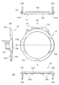
表示部保護ガラス11は、図6に拡大して示したように、中央部が周辺部よりも突出する曲面形状部11aとなっていて、その外側の周縁部が凹段部11bとなっている。表示部保護ガラス11の凹段部11bに金属製リング12が例えば両面接着テープにより接着して固定されている。
金属製リング12は、図2に示すように、内周側に傾斜面12aを有して、外周側が表示部保護ガラス11を覆うガラス外周覆い部12bを有するものである。
金属リング12を周縁部の凹段部11bに一体に固定した表示部保護ガラス11は、表ケース3の表示部33の周囲に両面接着テープにより周縁部で接着して固定されている。
【0012】
金属リング12の内周側の傾斜面12aを除いて外周部から外側を覆う円形枠状プロテクタ13は、図6及び図7に拡大して示したように、金属リング12のガラス外周覆い部12b及びその外周側を覆うリング部13aを有している。
円形枠状プロテクタ13は、リング部13aの外径が表ケース3の幅よりも大きく設定されていて、リング部13aの表面が表ケース3の表面及び表示部保護ガラス11の曲面形状部11aよりも突出するものである。
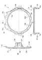
そして、リング部13aには、表面側へ僅かに突出して肉厚となる左右の曲面突出部13bと、上方へ突出する上部の接合片13cと、裏面側へ突出する下部の複数の差込片13dと、裏面側へ突出する左右の取付片13eとが形成されている。取付片13eは取付穴13fを有する。
【0013】
なお、図2に示すように、表ケース3の表示部保護ガラス11周囲の金属リング12の下部外側には、複数の差込穴3aが形成されている。
また、図3及び図4に示すように、裏ケース4内の上部左右には、前方へ突出する固定片49が備えられている。固定片49は雌ねじ50を有する。
【0014】
円形枠状プロテクタ13は、次のようにして機器ケース2に取り付けられる。
図2に示したように、表ケース3の金属製リング12の上下外側に沿ってに予め両面接着テープを接着しておく。そして、円形枠状プロテクタ13の差込片13dを表ケース3の差込穴3aに差し込んで、リング部13aで金属リング12のガラス外周覆い部12b及びその外周側を覆う。
このとき、接合片13aが表ケース3に両面接着テープで固定されるとともに、リング部13aの下側部分が表ケース3に両面接着テープで固定される。また、左右の取付片13eは、裏ケース4の固定片49の外側に重なる。
【0015】
その後、機器ケース2に上部緩衝部材5及び下部緩衝部材6を被せてビス止めする。上部緩衝部材5のビス止めに際して、取付片13eの外側に上部緩衝部材5の左右の延長部5aが重ねっており、図1に示すように、延長部5aからビス14を取付穴13fに位置する雌ねじ47に締め込む。
このような携帯電話機1の組立状態において、図1に示したように、円形枠状プロテクタ13のリング部13a及び曲面突出部13bが、機器ケース2(表ケース3)の左右両側に突出するとともに、表ケース3の表面及び表示部保護ガラス11の表面よりも突出している。
【0016】
以上の円形枠状プロテクタ13及び金属製リング12を表示部保護ガラス11に設けた携帯電話機1によれば、表示部保護ガラス11の周囲の円形枠状プロテクタ13及び金属製リング12によって、デザイン上の斬新感を付与できることに加え、耐衝撃性能が得られる。
すなわち、円形枠状プロテクタ13は、機器ケース2(表ケース3)の左右両側にリング部13a及び曲面突出部13bが突出しているので、左右両側からの衝撃に対して表示部保護ガラス11を保護できる。また、表ケース3の表面及び表示部保護ガラス11の表面よりもリング部13a及び曲面突出部13bが突出しているので、表側からの衝撃に対して表示部保護ガラス11を保護できる。
しかも、表示部保護ガラス11の周縁部に金属製リング12を一体化して設け、さらに、金属製リング12の周囲を円形枠状プロテクタ13で覆った構造なので、表示部保護ガラス11の周縁部に対する強度を向上できる。
【0017】
なお、以上の実施の形態においては、携帯電話機としたが、本発明はこれに限定されるものではなく、PHSや他の携帯端末機等の無線送受信機であっても良く、要は携帯通信機であれば良い。
また、表示部保護ガラスやプロテクタ(緩衝部材)や金属製リング(ベゼル)の材質・形状等も任意であり、例えば、リング12は金属製としたが、硬質の樹脂で成形したものであってもよい。なお、リング12を樹脂で成形する場合、塗装、メッキ、或いは蒸着等により、リング12の表面に見栄えのする色や金属光沢を付与するのがデザイン上望ましい。その他、具体的な細部構造等についても適宜に変更可能であることは勿論である。
【0018】
【発明の効果】
請求項1記載の発明によれば、表示部保護ガラスの周縁部に取り付けられたリング形状の枠部材によって表示部保護ガラスの強度を向上できるとともに、表示部保護ガラス周囲に設けたリング枠状の緩衝部材によって表示部保護ガラスを保護でき、また、このリング枠状の緩衝部材及び内周面側が露出する前記枠部材によって、デザイン上の斬新感も付与できる。
【0019】
請求項2記載の発明によれば、リング形状の枠部材の内周面側は傾斜面となっていて、枠部材の内周面側が見え易くなっているため、請求項1記載の発明により得られる効果に加え、枠部材による装飾効果が更に向上するといった効果が得られる。
請求項3記載の発明によれば、枠部材が、金属、又は、塗装、メッキ、或いは蒸着が施された硬質樹脂で構成されていて、枠部材の表面を金属光沢や見栄えする色にすることができるため、請求項1乃至2記載の発明により得られる効果に加え、枠部材による装飾効果が更に向上するといった効果が得られる。
請求項4記載の発明によれば、リング枠状の緩衝部材がケース本体よりも左右両側に突出しているため、請求項1乃至3記載の発明により得られる効果に加え、左右両側からの衝撃を吸収し、保護ガラスを保護できるといった効果が得られる。
請求項5記載の発明によれば、リング枠状の緩衝部材は、裏面側に突出する取付片を左右両側に有し、ケース本体の側面でビス止めされているため、請求項1乃至4記載の発明により得られる効果に加え、より強固にリング枠状の緩衝部材を固定できるといった効果が得られる。また表面側からビスが見えないのでデザイン上の見栄えを損なうことが無いといった効果も得られる。
【図面の簡単な説明】
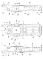
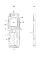
【図1】本発明を適用した一実施の形態の構成を示すもので、携帯通信機の一側面図(A)と正面図(B)と他側面図(C)である。
【図2】ケース本体の表ケースの正面図(A)と側面図(B)である。
【図3】ケース本体の裏ケースの正面図(A)と側面図(B)である。
【図4】アンテナの構造及び裏ケースへのアンテナの取付け状態を示す断面概略図である。
【図5】裏ケースへの回路ユニット及び表ケースの組み付けを示す分解側面図である。
【図6】表示部保護ガラスを拡大して示したもので、正面図(A)とその矢印B−B線に沿った断面図(B)である。
【図7】枠状の緩衝部材を拡大して示したもので、正面図(A)とその矢印B、C、D方向から見た側面図(B)(C)(D)である。
【図8】枠状の緩衝部材の背面図(A)とその矢印B−B線、C−C線に沿った断面図(B)(C)である。
【符号の説明】
1 携帯通信機
2 ケース本体
3 表ケース
3a 差込穴
31 マイク
32 各種操作キー部
33 表示部
34 スピーカ
4 裏ケース
41 アンテナ装着部
42 電池蓋
43 イヤホンカバー
45 コネクタカバー
49 固定片
50 雌ねじ
5 上部緩衝部材
5a 延長部
6 下部緩衝部材
7 アンテナ
8 回路ユニット
9 ビス
11 表示部保護ガラス
11a 曲面形状部
11b 凹段部
12 金属製枠部材
12a 傾斜面
12b ガラス外周覆い部
13 枠状緩衝部材
13a リング部
13b 曲面状凸部
13c 接合片
13d 差込片
13e 取付片
13f 取付穴
14 ビス[0001]
BACKGROUND OF THE INVENTION
The present invention relates to a portable communication device, and more particularly to a display unit protection structure for a portable communication device.
[0002]
[Prior art]
In a portable communication device such as a cellular phone, a display unit provided in a device case is covered with protective glass.
Conventionally, in the portable communication device, the surface of the protective glass of the display unit is substantially flush with the surface of the device case.
[0003]
[Problems to be solved by the invention]
However, the display unit of recent portable communication devices has become larger, and when the case surface is flush with the case surface as before, there is a higher risk of the protective glass of the display unit being broken or wrinkled. It is coming.
[0004]
The subject of this invention is protecting a protective glass of a display part in a portable communication apparatus provided with a display part protective glass.
[0005]
[Means for Solving the Problems]
In order to solve the above problems, the invention described in
According to the first aspect of the present invention, the strength of the display unit protection glass can be improved by the ring-shaped frame member having rigidity attached to the peripheral part of the display unit protection glass, and provided around the display unit protection glass. Further , the protective glass of the display unit can be protected by the ring frame-shaped buffer member protruding from the surface of the display unit protective glass and the surface of the case body, and the ring frame-shaped buffer member and the inner peripheral surface side are exposed. The frame member can give a novel design.
Furthermore, shocks from the upper and lower directions can be absorbed by the upper and lower cushioning members of the case, and the protective glass can be protected.
Here, the mobile communication device is typically a mobile phone (including PHS), but may be a wireless transceiver such as another mobile terminal. Examples of the protective glass for the display portion include acrylic artificial glass, but natural glass may be used, and it is desirable that the surface be hard-coated. Further, the protection glass is circular in the embodiment, also it is assumed to also involve the frame member of ring-shaped circular it, they may be of elliptical or polygonal, may be of any shape . As the buffer member, a soft resin or a hard resin may be used.
[0006]
According to the second aspect of the present invention, in the
According to a third aspect of the present invention, in the
The invention of
According to a fifth aspect of the invention, in the
[0007]
DETAILED DESCRIPTION OF THE INVENTION
Hereinafter, embodiments of the present invention will be described in detail with reference to the drawings.
As shown in FIG. 1, in a
On the surface of the
The
[0008]
As shown in the schematic cross-sectional view of FIG. 4, the
The
The
In FIG. 4, 41 b is an O-ring (waterproof ring) that bears waterproofing between the
An O-ring (waterproof ring) is also provided in the
The pull-out
[0009]
As shown in FIG. 5, a
[0010]
The
Further, a circular frame-shaped protector (buffer member) 13 made of a soft resin that covers the outer periphery of the
[0011]
As shown in FIG. 6 in an enlarged manner, the display
As shown in FIG. 2, the
The display
[0012]
The circular frame-shaped
In the circular frame-shaped
The
[0013]
As shown in FIG. 2, a plurality of
Further, as shown in FIGS. 3 and 4, a fixing
[0014]
The
As shown in FIG. 2, a double-sided adhesive tape is bonded in advance along the upper and lower outer sides of the
At this time, the joining
[0015]
Thereafter, the upper shock-absorbing
In such an assembled state of the
[0016]
According to the
That is, since the
Moreover, since the
[0017]
In the above embodiment, the cellular phone is used. However, the present invention is not limited to this, and may be a wireless transceiver such as a PHS or another portable terminal. If it is a machine.
Further, the material and shape of the display portion protection glass, the protector (buffer member), and the metal ring (bezel) are arbitrary. For example, the
[0018]
【The invention's effect】
According to the first aspect of the present invention, the strength of the display portion protection glass can be improved by the ring-shaped frame member attached to the peripheral portion of the display portion protection glass, and the ring frame-like shape provided around the display portion protection glass. depending on the buffer member can be protected Table radical 113 protective glass, also by the frame member in which the buffer member and the inner circumferential surface of the ring frame shape is exposed it can also be imparted novel sense of design.
[0019]
According to the invention described in
According to the invention of
According to the invention described in
According to the invention of
[Brief description of the drawings]
FIG. 1 shows a configuration of an embodiment to which the present invention is applied, and is a side view (A), a front view (B), and another side view (C) of a portable communication device.
FIG. 2 is a front view (A) and a side view (B) of a front case of a case body.
FIG. 3 is a front view (A) and a side view (B) of a back case of the case body.
FIG. 4 is a schematic cross-sectional view showing the structure of the antenna and the state of attachment of the antenna to the back case.
FIG. 5 is an exploded side view showing the assembly of the circuit unit and the front case to the back case.
6 is an enlarged view of the display portion protection glass, and is a front view (A) and a sectional view (B) taken along the line BB.
FIG. 7 is an enlarged view of a frame-shaped buffer member, which is a front view (A) and side views (B), (C), and (D) viewed from the directions of arrows B, C, and D thereof.
FIGS. 8A and 8B are a rear view (A) of a frame-shaped buffer member and cross-sectional views (B) and (C) along arrows BB and CC, respectively.
[Explanation of symbols]
DESCRIPTION OF
Claims (5)
前記表示部の上面には、周縁部に剛性を有するとともに装飾機能を有するリング形状の枠部材が取り付けられるとともに中央部が周辺部よりも突出する曲面形状の保護ガラスが設けられ、
前記保護ガラスの周囲は、前記ケース本体の表面及び前記保護ガラスの曲面形状部よりも突出するリング枠状の緩衝部材により、前記枠部材の内周面側が装飾部として露出する状態で囲まれており、
更に前記ケース本体の上部及び下部には、上部緩衝部材及び下部緩衝部材が設けられている、
ことを特徴とする携帯通信機。In a portable portable communication device provided with a display unit in the case body,
On the upper surface of the display portion, a ring-shaped frame member having rigidity and a decorative function is attached to the peripheral portion, and a curved protective glass with a central portion protruding from the peripheral portion is provided,
The periphery of the protective glass is surrounded by a ring frame-shaped cushioning member protruding from the surface of the case body and the curved shape portion of the protective glass in a state where the inner peripheral surface side of the frame member is exposed as a decorative portion. And
Furthermore, an upper buffer member and a lower buffer member are provided on the upper and lower portions of the case body,
A portable communication device characterized by that.
Priority Applications (1)
| Application Number | Priority Date | Filing Date | Title |
|---|---|---|---|
| JP2000024148A JP4296670B2 (en) | 2000-02-01 | 2000-02-01 | Portable communication device |
Applications Claiming Priority (1)
| Application Number | Priority Date | Filing Date | Title |
|---|---|---|---|
| JP2000024148A JP4296670B2 (en) | 2000-02-01 | 2000-02-01 | Portable communication device |
Publications (3)
| Publication Number | Publication Date |
|---|---|
| JP2001215885A JP2001215885A (en) | 2001-08-10 |
| JP2001215885A5 JP2001215885A5 (en) | 2005-11-10 |
| JP4296670B2 true JP4296670B2 (en) | 2009-07-15 |
Family
ID=18550194
Family Applications (1)
| Application Number | Title | Priority Date | Filing Date |
|---|---|---|---|
| JP2000024148A Expired - Fee Related JP4296670B2 (en) | 2000-02-01 | 2000-02-01 | Portable communication device |
Country Status (1)
| Country | Link |
|---|---|
| JP (1) | JP4296670B2 (en) |
Families Citing this family (3)
| Publication number | Priority date | Publication date | Assignee | Title |
|---|---|---|---|---|
| CN100512328C (en) | 2000-12-29 | 2009-07-08 | 弗图有限公司 | Casing |
| GB2374235B (en) * | 2000-12-29 | 2004-09-22 | Nokia Mobile Phones Ltd | A casing |
| CN102869211A (en) * | 2011-07-08 | 2013-01-09 | 深圳富泰宏精密工业有限公司 | Casing and manufacturing method thereof |
-
2000
- 2000-02-01 JP JP2000024148A patent/JP4296670B2/en not_active Expired - Fee Related
Also Published As
| Publication number | Publication date |
|---|---|
| JP2001215885A (en) | 2001-08-10 |
Similar Documents
| Publication | Publication Date | Title |
|---|---|---|
| US10158163B2 (en) | Mobile terminal | |
| US20020137475A1 (en) | Anti electromagnetic wave box for a mobile phone | |
| KR101066162B1 (en) | Mobilephone protect case for bar-type mobilephone | |
| KR20100132575A (en) | Speaker device for portable terminal | |
| JP2001189786A (en) | Portable radio communication equipment such as portable telephone | |
| US10263658B2 (en) | Protective cover and electronic device having it | |
| JP4296670B2 (en) | Portable communication device | |
| JPH04220851A (en) | Cordless telephone set | |
| NZ286970A (en) | Communications handset with electrostatic screen gasket | |
| EP1393408A1 (en) | Safety shield | |
| KR101239281B1 (en) | Protect case for mobile device seperated buffer members and deco members | |
| KR100735245B1 (en) | Protable terminal with dummy pad for ground | |
| KR100421737B1 (en) | Electrostatic discharge prevention and electromagnetic wave absorbing and shielding method for hand-carry wireless telecommunication terminal making use of electrified shielding board and electrified LCD cushion, electrified accessory for grounding | |
| KR100651494B1 (en) | Protable terminal with dummy pad for ground | |
| KR101583566B1 (en) | a smart phone case for electromagnetic wave shield | |
| WO2019001465A1 (en) | Decorative component and electronic device | |
| KR101090217B1 (en) | Mobile Phone Case Assembly | |
| JP2009239670A (en) | Display device for mobile terminal and mobile terminal equipped with the same | |
| KR200164645Y1 (en) | A sticker of the portable telephone shielding electromagnetic wave | |
| CA2534933C (en) | Portable communication device with swiveling key | |
| JP2003249991A (en) | Mobile phone | |
| CN214756491U (en) | Protective housing with dustproof function | |
| CN210780952U (en) | Waterproof protective shell | |
| JP2006019909A (en) | Mobile terminal and mobile terminal cover used for the same | |
| JPH10308595A (en) | Portable telephone case for cutting off radio wave |
Legal Events
| Date | Code | Title | Description |
|---|---|---|---|
| A521 | Written amendment |
Free format text: JAPANESE INTERMEDIATE CODE: A523 Effective date: 20050920 |
|
| A621 | Written request for application examination |
Free format text: JAPANESE INTERMEDIATE CODE: A621 Effective date: 20050920 |
|
| A131 | Notification of reasons for refusal |
Free format text: JAPANESE INTERMEDIATE CODE: A131 Effective date: 20080916 |
|
| A521 | Written amendment |
Free format text: JAPANESE INTERMEDIATE CODE: A523 Effective date: 20081117 |
|
| TRDD | Decision of grant or rejection written | ||
| A01 | Written decision to grant a patent or to grant a registration (utility model) |
Free format text: JAPANESE INTERMEDIATE CODE: A01 Effective date: 20090324 |
|
| A01 | Written decision to grant a patent or to grant a registration (utility model) |
Free format text: JAPANESE INTERMEDIATE CODE: A01 |
|
| A61 | First payment of annual fees (during grant procedure) |
Free format text: JAPANESE INTERMEDIATE CODE: A61 Effective date: 20090406 |
|
| R150 | Certificate of patent or registration of utility model |
Free format text: JAPANESE INTERMEDIATE CODE: R150 |
|
| FPAY | Renewal fee payment (event date is renewal date of database) |
Free format text: PAYMENT UNTIL: 20120424 Year of fee payment: 3 |
|
| FPAY | Renewal fee payment (event date is renewal date of database) |
Free format text: PAYMENT UNTIL: 20120424 Year of fee payment: 3 |
|
| FPAY | Renewal fee payment (event date is renewal date of database) |
Free format text: PAYMENT UNTIL: 20130424 Year of fee payment: 4 |
|
| FPAY | Renewal fee payment (event date is renewal date of database) |
Free format text: PAYMENT UNTIL: 20130424 Year of fee payment: 4 |
|
| FPAY | Renewal fee payment (event date is renewal date of database) |
Free format text: PAYMENT UNTIL: 20140424 Year of fee payment: 5 |
|
| LAPS | Cancellation because of no payment of annual fees |